EP1467393A2 - Schnappfedertaster - Google Patents
Schnappfedertaster Download PDFInfo
- Publication number
- EP1467393A2 EP1467393A2 EP04007950A EP04007950A EP1467393A2 EP 1467393 A2 EP1467393 A2 EP 1467393A2 EP 04007950 A EP04007950 A EP 04007950A EP 04007950 A EP04007950 A EP 04007950A EP 1467393 A2 EP1467393 A2 EP 1467393A2
- Authority
- EP
- European Patent Office
- Prior art keywords
- snap spring
- actuating element
- snap
- rocker arm
- housing
- Prior art date
- Legal status (The legal status is an assumption and is not a legal conclusion. Google has not performed a legal analysis and makes no representation as to the accuracy of the status listed.)
- Withdrawn
Links
- 238000006073 displacement reaction Methods 0.000 claims abstract 2
- 230000000694 effects Effects 0.000 description 3
- 238000000034 method Methods 0.000 description 3
- 230000008878 coupling Effects 0.000 description 2
- 238000010168 coupling process Methods 0.000 description 2
- 238000005859 coupling reaction Methods 0.000 description 2
- 238000010276 construction Methods 0.000 description 1
- 229910000679 solder Inorganic materials 0.000 description 1
- 238000005476 soldering Methods 0.000 description 1
Images
Classifications
-
- H—ELECTRICITY
- H01—ELECTRIC ELEMENTS
- H01H—ELECTRIC SWITCHES; RELAYS; SELECTORS; EMERGENCY PROTECTIVE DEVICES
- H01H23/00—Tumbler or rocker switches, i.e. switches characterised by being operated by rocking an operating member in the form of a rocker button
- H01H23/02—Details
- H01H23/12—Movable parts; Contacts mounted thereon
- H01H23/16—Driving mechanisms
- H01H23/20—Driving mechanisms having snap action
-
- H—ELECTRICITY
- H01—ELECTRIC ELEMENTS
- H01H—ELECTRIC SWITCHES; RELAYS; SELECTORS; EMERGENCY PROTECTIVE DEVICES
- H01H23/00—Tumbler or rocker switches, i.e. switches characterised by being operated by rocking an operating member in the form of a rocker button
- H01H23/28—Tumbler or rocker switches, i.e. switches characterised by being operated by rocking an operating member in the form of a rocker button with three operating positions
- H01H23/30—Tumbler or rocker switches, i.e. switches characterised by being operated by rocking an operating member in the form of a rocker button with three operating positions with stable centre positions and one or both end positions unstable
Definitions
- the invention relates to a snap spring switch with a housing, in which at least a snap spring is tensioned at a bearing point.
- a force application device which is coupled to a displaceable actuating element, moves the actuating element, the actuating element being displaced acts on the snap spring.
- Such a snap spring switch, for. B. designed as a rocker switch module can for Seat adjustments, mirror adjustments, logic switches, sunroofs in motor vehicles and the like. Applications are also for adjustments in seating furniture and beds, for example hospital beds, realizable.
- a rocker-operated switch with a two-part housing is from the generic DE 38 01 991 A1 known in which the rocker arm is pivotable is stored within the housing.
- the pivoting movement of the rocker arm will over a foot that is in a cuff-shaped receptacle of a plate-shaped Slider engages.
- the slide is perpendicular to that through the pivot pin of the rocker arm fixed pivot axis.
- the linear displaceability The operating slide has the disadvantage that high operating forces become necessary and that the sliding piece to high frictional resistance or tends to tilt. Furthermore, drawstrings of the snap spring are not evenly loaded, which affects the life of the Snap spring button leads.
- the object of the invention is to provide an improvement over the prior art To provide snap spring buttons.
- a further development of the invention provides that the pivot axis of the actuating element is arranged parallel to the bearing axis of the snap spring, assuming that the snap spring pivots about an axis opposite contact means passing through the button can be switched accordingly.
- the snap spring is frame-like with one projecting inwards Tongue designed to tension the snap spring at the bearing points.
- the pivot axis of the actuating element is parallel to the plane the snap spring and perpendicular to the longitudinal extension of the spring, being thereof it is assumed that the snap spring is essentially rectangular is. With a different geometry of the snap spring, it is provided that the pivot axis of the actuator is perpendicular to the direction of movement of contacts.
- the force introduction device is in the form of a rocker arm trained, because the rocker arm simple operation and adjustment the actuating force can be realized via the lever ratio.
- the rocker arm is pivotally mounted in the housing, the pivot axis of the rocker arm substantially perpendicular to the pivot axis of the actuating element is arranged.
- the rocker arm is form-fitting with the actuating element coupled, that is, the rocker arm with a tongue and groove principle engages around the actuating element or in a recess of the actuating element engages and the movement about the pivot axis of the actuating element causes.
- a further development of the invention provides that the housing in one piece, that is is constructed without a floor or lid, so that a small space requirement of the Snap spring push button module can be realized. So that mechanical forces not transferred into the soldering points of the connection pieces by the switching process can be provided in an advantageous development that the Housing on a circuit board via a releasable mechanical connection, in particular is fixed via a screw connection.
- both snap springs are advantageously in the starting position on the actuator so that an exact reset the rocker arm and the actuator, and a fixation of the rocker arm and actuator in the starting position and thus in the non-switched position.
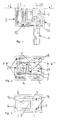
- a snap spring button 1 is shown in cross-sectional view in FIG Can be mechanically fixed by a screw 10 to a circuit board, not shown is.
- the screw 10 is in a corresponding guide of a housing 2 arranged, the housing 2 is integrally formed and the lower Completion is realized by the circuit board.
- the detachable mechanical coupling to the circuit board via the screw 10 has the advantage that forces, which is initiated via a rocker arm 6 for switching an actuating element 7 are not transferred to the solder joints of the connectors 20.
- the rocker arm 6 is pivotally mounted in the housing 2 via pins, wherein pivoting about the pivot axis 16 takes place.
- FIG. 2 shows a top view of the switch according to FIG. 1, from which It can be seen that two snap springs 4, 5 on the side of the actuating element 7 are stored.
- the snap springs 4, 5 are stored at bearing points 3, 3 ', wherein at one bearing 3 a pivot axis 9, as in the Figure 3 is shown, is formed, while in the bearing 3 'a tongue 14 engages, whose function will be explained later.
- At the pivot axis 9 opposite end of the snap springs 4, 5 are formed contacts effect a corresponding circuit between the connectors 21.
- FIG. 3 shows the frame-like configuration of the snap spring 4, which has an inwardly projecting tongue 14 in a corresponding bearing 3 'of a connector 8 engages.
- the arched when assembled trained tongue 14 causes a bias and a tension of the Snap spring 4, 5 and has the effect that both the actuating element 7 as well as the rocker arm 6 returned to their starting position after the switching operation become.
- the pivot axis 16 of the rocker arm 6, which advantageously through the pivot axis 17 of the actuating element 7 runs arranged snap springs 4, 5 can alternately Circuit in both pivot directions of the rocker arm 6 and an exact reset take place since the actuating element 7 with its two ends on the Snap springs 4, 5 abut.
- FIG. 1 in particular shows the particularly simple construction of the housing 2 with corresponding bearings for the rocker arm 6 and corresponding receptacles and inserts for the connectors 8 and the connectors 21 for the contacts and the switching mimicry, so that an assembly by feeding the Elements can be made from essentially one direction of assembly.
- the assembly can take place without an additional lid or bottom, which reduces both the parts and the assembly effort and also realized a reduced space requirement.
- a particular advantage of the invention is that it is easy to switch Rocker arm 6, the snap springs 4, 5 evenly over the actuating element 7 controls, the actuating element 7 are not linearly displaced must, but performs a rotational movement.
Landscapes
- Mechanisms For Operating Contacts (AREA)
Abstract
Description
- Figur 1 -
- ein Schnappfedertaster im Querschnitt;
- Figur 2 -
- ein Schnappfedertaster gemäß der Schnittlinie II-II in Figur 1; sowie
- Figur 3 -
- eine Schnittdarstellung gemäß Linie III-III in Figur 2.
Claims (10)
- Schnappfedertaster mit einem Gehäuse (2), zumindest einer an Lagerstellen (3, 3') gespannten Schnappfeder (4, 5) und einer Krafteinleiteinrichtung (6), die mit einem verlagerbaren Betätigungselement (7) gekoppelt ist, wobei das Betätigungselement (7) bei dessen Verlagerung auf die Schnappfeder (4, 5) einwirkt, dadurch gekennzeichnet, dass das Betätigungselement (7) um eine Achse (17) verschwenkbar gelagert ist.
- Schnappfedertaster nach Anspruch 1, dadurch gekennzeichnet, dass die Schwenkachse (17) des Betätigungselementes (7) parallel zu Lagerachse (9) der Schnappfeder (4, 5) angeordnet ist.
- Schnappfedertaster nach Anspruch 1 oder 2, dadurch gekennzeichnet, dass die Schnappfeder (4, 5) rahmenartig mit einer nach innen ragenden Zunge (14) ausgebildet ist und die Schwenkachse (17) des Betätigungselementes (7) parallel zu der Ebene der Schnappfeder (4, 5) und senkrecht zu deren Längserstreckung angeordnet ist.
- Schnappfedertaster nach einem der voranstehenden Ansprüche, dadurch gekennzeichnet, dass die Krafteinleiteinrichtung (6) als ein Kipphebel ausgebildet ist, der schwenkbar in dem Gehäuse (2) gelagert ist, wobei die Schwenkachse (16) des Kipphebels (6) senkrecht zur Schwenkachse (17) des Betätigungselementes (7) angeordnet ist.
- Schnappfedertaster nach Anspruch 4, dadurch gekennzeichnet, dass der Kipphebel (6) formschlüssig mit dem Betätigungselement (7) gekoppelt ist.
- Schnappfedertaster nach einem der voranstehenden Ansprüche, dadurch gekennzeichnet, dass das Gehäuse (2) einstückig ausgebildet ist.
- Schnappfedertaster nach einem der voranstehenden Ansprüche, dadurch gekennzeichnet, dass das Gehäuse (2) auf einer Leiterplatte über eine lösbare mechanische Verbindung, insbesondere Schraubverbindung festgelegt ist.
- Schnappfedertaster nach einem der voranstehenden Ansprüche, dadurch gekennzeichnet, dass zwei Schnappfedern (4, 5) beidseitig des Betätigungselementes (7) angeordnet sind.
- Schnappfedertaster nach Anspruch 8, dadurch gekennzeichnet, dass die beiden Schnappfedern (4, 5) in der Ausgangsstellung an dem Betätigungselement (7) anliegen.
- Schnappfedertaster nach einem der voranstehenden Ansprüche, dadurch gekennzeichnet, dass der Schnappfedertaster als Modul ausgebildet ist und dass Lagerstellen für einen Kipphebel (6) und Aufnahmen und Einsätze für Anschlussstücke (8) sowie Anschlüsse (21) für Kontakte so ausgebildet sind, dass eine Montage durch Zuführen der Elemente aus im wesentlichen einer Montagerichtung erfolgen kann.
Applications Claiming Priority (2)
| Application Number | Priority Date | Filing Date | Title |
|---|---|---|---|
| DE10316338 | 2003-04-10 | ||
| DE2003116338 DE10316338B3 (de) | 2003-04-10 | 2003-04-10 | Schnappfedertaster |
Publications (2)
| Publication Number | Publication Date |
|---|---|
| EP1467393A2 true EP1467393A2 (de) | 2004-10-13 |
| EP1467393A3 EP1467393A3 (de) | 2006-05-03 |
Family
ID=32864410
Family Applications (1)
| Application Number | Title | Priority Date | Filing Date |
|---|---|---|---|
| EP04007950A Withdrawn EP1467393A3 (de) | 2003-04-10 | 2004-04-01 | Schnappfedertaster |
Country Status (2)
| Country | Link |
|---|---|
| EP (1) | EP1467393A3 (de) |
| DE (1) | DE10316338B3 (de) |
Citations (4)
| Publication number | Priority date | Publication date | Assignee | Title |
|---|---|---|---|---|
| DE3308188A1 (de) | 1983-03-08 | 1984-09-20 | Georg Dr.-Ing. 8152 Feldkirchen-Westerham Spinner | Schnappschalter |
| EP0515269A1 (de) | 1991-05-22 | 1992-11-25 | Dav | Elektrischer Schnappschalter und aus mehreren Abteilen bestehende Schalteinheit |
| DE4331445A1 (de) | 1993-09-16 | 1995-03-23 | Eaton Controls Gmbh & Co | Kippschalter, insbesondere für Kraftfahrzeuge |
| DE19924059C2 (de) | 1999-05-26 | 2003-02-20 | Cherry Gmbh | Mechanisch betätigbarer Schnappfederschalter |
Family Cites Families (3)
| Publication number | Priority date | Publication date | Assignee | Title |
|---|---|---|---|---|
| CH465058A (de) * | 1965-08-12 | 1968-11-15 | Frako Kondensatoren Und App Ba | Vorschaltgerät für aus dem Wechselstromnetz gespeiste Gasentladungslampen |
| DE3801991A1 (de) * | 1988-01-23 | 1989-08-03 | Kostal Leopold Gmbh & Co Kg | Kipphebelbetaetigter schnappfederschalter |
| IT231473Y1 (it) * | 1993-08-11 | 1999-08-03 | Valvar Srl | Interruttore a scatto rapido per il comando di un dispositivo elettrico |
-
2003
- 2003-04-10 DE DE2003116338 patent/DE10316338B3/de not_active Expired - Fee Related
-
2004
- 2004-04-01 EP EP04007950A patent/EP1467393A3/de not_active Withdrawn
Patent Citations (4)
| Publication number | Priority date | Publication date | Assignee | Title |
|---|---|---|---|---|
| DE3308188A1 (de) | 1983-03-08 | 1984-09-20 | Georg Dr.-Ing. 8152 Feldkirchen-Westerham Spinner | Schnappschalter |
| EP0515269A1 (de) | 1991-05-22 | 1992-11-25 | Dav | Elektrischer Schnappschalter und aus mehreren Abteilen bestehende Schalteinheit |
| DE4331445A1 (de) | 1993-09-16 | 1995-03-23 | Eaton Controls Gmbh & Co | Kippschalter, insbesondere für Kraftfahrzeuge |
| DE19924059C2 (de) | 1999-05-26 | 2003-02-20 | Cherry Gmbh | Mechanisch betätigbarer Schnappfederschalter |
Also Published As
| Publication number | Publication date |
|---|---|
| DE10316338B3 (de) | 2004-11-18 |
| EP1467393A3 (de) | 2006-05-03 |
Similar Documents
| Publication | Publication Date | Title |
|---|---|---|
| DE10005895C2 (de) | Monostabiler Miniaturschalter | |
| DE29614023U1 (de) | Computertaste | |
| DE10223502A1 (de) | Sockel für ein IC-Gehäuse | |
| WO2018224094A1 (de) | Stellvorrichtung | |
| EP2184754B1 (de) | Schalter | |
| EP2174330B1 (de) | Mikroschalter | |
| DE602006000121T2 (de) | Schaltervorrichtung für Fahrrichtungsanzeige | |
| DE60103235T2 (de) | Druckschalter für Starkstrom | |
| DE69707867T2 (de) | Schaltvorrichtung für elektrische Schaltungen | |
| DE10316338B3 (de) | Schnappfedertaster | |
| AT409428B (de) | Elektrischer installationsschalter | |
| WO2008052746A1 (de) | Höhenverstellbare armlehne, insbesondere für einen bürostuhl | |
| DE3912798A1 (de) | Schaltmechanik fuer einen tastschalter | |
| DE3126816C2 (de) | ||
| DE102006010828B3 (de) | Elektrisches Schaltelement, insbesondere Relais, mit Schwenkhebel-Schaltmechanik | |
| EP1192057A1 (de) | Gestängeteil für ein verstellbares fahrzeugdach | |
| DE102019132339A1 (de) | Vorrichtung zur Steuerung eines elektronischen Gerätes, Verfahren zur Einstellung der Vorrichtung und Rückspiegel eines Kraftfahrzeugs, der eine solche Vorrichtung enthält | |
| EP0433702B1 (de) | Hebelwerk | |
| DE29802820U1 (de) | Vorrichtung für das Ein- und Ausschalten eines Elektromotors, insbesondere eines Elektrowerkzeugs | |
| EP0939416B1 (de) | Druckbetätigter Schalter | |
| DE102006044055B4 (de) | Elektrisches Schaltgerät mit wenigstens einer Kontaktstelle | |
| DE102007022690B4 (de) | Zentriervorrichtung für elektronische Bauelemente | |
| DE2019885B2 (de) | Springkontaktsatz | |
| DE4323878A1 (de) | Tastmodul zum Schalten | |
| EP0716822B1 (de) | Federelement |
Legal Events
| Date | Code | Title | Description |
|---|---|---|---|
| PUAI | Public reference made under article 153(3) epc to a published international application that has entered the european phase |
Free format text: ORIGINAL CODE: 0009012 |
|
| AK | Designated contracting states |
Kind code of ref document: A2 Designated state(s): AT BE BG CH CY CZ DE DK EE ES FI FR GB GR HU IE IT LI LU MC NL PL PT RO SE SI SK TR |
|
| AX | Request for extension of the european patent |
Extension state: AL HR LT LV MK |
|
| PUAL | Search report despatched |
Free format text: ORIGINAL CODE: 0009013 |
|
| AK | Designated contracting states |
Kind code of ref document: A3 Designated state(s): AT BE BG CH CY CZ DE DK EE ES FI FR GB GR HU IE IT LI LU MC NL PL PT RO SE SI SK TR |
|
| AX | Request for extension of the european patent |
Extension state: AL HR LT LV MK |
|
| 17P | Request for examination filed |
Effective date: 20061103 |
|
| AKX | Designation fees paid |
Designated state(s): DE FR IT |
|
| 17Q | First examination report despatched |
Effective date: 20080422 |
|
| STAA | Information on the status of an ep patent application or granted ep patent |
Free format text: STATUS: THE APPLICATION IS DEEMED TO BE WITHDRAWN |
|
| 18D | Application deemed to be withdrawn |
Effective date: 20090915 |