EP1467270A2 - Terminal table unit - Google Patents
Terminal table unit Download PDFInfo
- Publication number
- EP1467270A2 EP1467270A2 EP04004595A EP04004595A EP1467270A2 EP 1467270 A2 EP1467270 A2 EP 1467270A2 EP 04004595 A EP04004595 A EP 04004595A EP 04004595 A EP04004595 A EP 04004595A EP 1467270 A2 EP1467270 A2 EP 1467270A2
- Authority
- EP
- European Patent Office
- Prior art keywords
- input data
- table unit
- terminal table
- control device
- data
- Prior art date
- Legal status (The legal status is an assumption and is not a legal conclusion. Google has not performed a legal analysis and makes no representation as to the accuracy of the status listed.)
- Withdrawn
Links
Images




Classifications
-
- G—PHYSICS
- G05—CONTROLLING; REGULATING
- G05B—CONTROL OR REGULATING SYSTEMS IN GENERAL; FUNCTIONAL ELEMENTS OF SUCH SYSTEMS; MONITORING OR TESTING ARRANGEMENTS FOR SUCH SYSTEMS OR ELEMENTS
- G05B19/00—Program-control systems
- G05B19/02—Program-control systems electric
- G05B19/04—Program control other than numerical control, i.e. in sequence controllers or logic controllers
- G05B19/05—Programmable logic controllers, e.g. simulating logic interconnections of signals according to ladder diagrams or function charts
-
- A—HUMAN NECESSITIES
- A47—FURNITURE; DOMESTIC ARTICLES OR APPLIANCES; COFFEE MILLS; SPICE MILLS; SUCTION CLEANERS IN GENERAL
- A47G—HOUSEHOLD OR TABLE EQUIPMENT
- A47G9/00—Bed-covers; Counterpanes; Travelling rugs; Sleeping rugs; Sleeping bags; Pillows
-
- A—HUMAN NECESSITIES
- A47—FURNITURE; DOMESTIC ARTICLES OR APPLIANCES; COFFEE MILLS; SPICE MILLS; SUCTION CLEANERS IN GENERAL
- A47G—HOUSEHOLD OR TABLE EQUIPMENT
- A47G9/00—Bed-covers; Counterpanes; Travelling rugs; Sleeping rugs; Sleeping bags; Pillows
- A47G9/007—Bed-covers; Counterpanes; Travelling rugs; Sleeping rugs; Sleeping bags; Pillows comprising deodorising, fragrance releasing, therapeutic or disinfecting substances
-
- A—HUMAN NECESSITIES
- A47—FURNITURE; DOMESTIC ARTICLES OR APPLIANCES; COFFEE MILLS; SPICE MILLS; SUCTION CLEANERS IN GENERAL
- A47G—HOUSEHOLD OR TABLE EQUIPMENT
- A47G9/00—Bed-covers; Counterpanes; Travelling rugs; Sleeping rugs; Sleeping bags; Pillows
- A47G9/02—Bed linen; Blankets; Counterpanes
-
- A—HUMAN NECESSITIES
- A47—FURNITURE; DOMESTIC ARTICLES OR APPLIANCES; COFFEE MILLS; SPICE MILLS; SUCTION CLEANERS IN GENERAL
- A47G—HOUSEHOLD OR TABLE EQUIPMENT
- A47G9/00—Bed-covers; Counterpanes; Travelling rugs; Sleeping rugs; Sleeping bags; Pillows
- A47G9/10—Pillows
-
- A—HUMAN NECESSITIES
- A47—FURNITURE; DOMESTIC ARTICLES OR APPLIANCES; COFFEE MILLS; SPICE MILLS; SUCTION CLEANERS IN GENERAL
- A47G—HOUSEHOLD OR TABLE EQUIPMENT
- A47G9/00—Bed-covers; Counterpanes; Travelling rugs; Sleeping rugs; Sleeping bags; Pillows
- A47G2009/001—Anti-allergen; Anti-mite
-
- G—PHYSICS
- G05—CONTROLLING; REGULATING
- G05B—CONTROL OR REGULATING SYSTEMS IN GENERAL; FUNCTIONAL ELEMENTS OF SUCH SYSTEMS; MONITORING OR TESTING ARRANGEMENTS FOR SUCH SYSTEMS OR ELEMENTS
- G05B2219/00—Program-control systems
- G05B2219/10—Plc systems
- G05B2219/13—Plc programming
- G05B2219/13161—Easily exchangable rom, eprom cassette, earom
-
- G—PHYSICS
- G05—CONTROLLING; REGULATING
- G05B—CONTROL OR REGULATING SYSTEMS IN GENERAL; FUNCTIONAL ELEMENTS OF SUCH SYSTEMS; MONITORING OR TESTING ARRANGEMENTS FOR SUCH SYSTEMS OR ELEMENTS
- G05B2219/00—Program-control systems
- G05B2219/10—Plc systems
- G05B2219/13—Plc programming
- G05B2219/13171—Portable, detachable programming unit
-
- G—PHYSICS
- G05—CONTROLLING; REGULATING
- G05B—CONTROL OR REGULATING SYSTEMS IN GENERAL; FUNCTIONAL ELEMENTS OF SUCH SYSTEMS; MONITORING OR TESTING ARRANGEMENTS FOR SUCH SYSTEMS OR ELEMENTS
- G05B2219/00—Program-control systems
- G05B2219/10—Plc systems
- G05B2219/14—Plc safety
- G05B2219/14067—Log, history of key, input information before last fault occurred
-
- G—PHYSICS
- G05—CONTROLLING; REGULATING
- G05B—CONTROL OR REGULATING SYSTEMS IN GENERAL; FUNCTIONAL ELEMENTS OF SUCH SYSTEMS; MONITORING OR TESTING ARRANGEMENTS FOR SUCH SYSTEMS OR ELEMENTS
- G05B2219/00—Program-control systems
- G05B2219/20—Pc systems
- G05B2219/23—Pc programming
- G05B2219/23363—Barcode
-
- G—PHYSICS
- G05—CONTROLLING; REGULATING
- G05B—CONTROL OR REGULATING SYSTEMS IN GENERAL; FUNCTIONAL ELEMENTS OF SUCH SYSTEMS; MONITORING OR TESTING ARRANGEMENTS FOR SUCH SYSTEMS OR ELEMENTS
- G05B2219/00—Program-control systems
- G05B2219/20—Pc systems
- G05B2219/24—Pc safety
- G05B2219/24055—Trace, store a working, operation history
-
- Y—GENERAL TAGGING OF NEW TECHNOLOGICAL DEVELOPMENTS; GENERAL TAGGING OF CROSS-SECTIONAL TECHNOLOGIES SPANNING OVER SEVERAL SECTIONS OF THE IPC; TECHNICAL SUBJECTS COVERED BY FORMER USPC CROSS-REFERENCE ART COLLECTIONS [XRACs] AND DIGESTS
- Y02—TECHNOLOGIES OR APPLICATIONS FOR MITIGATION OR ADAPTATION AGAINST CLIMATE CHANGE
- Y02P—CLIMATE CHANGE MITIGATION TECHNOLOGIES IN THE PRODUCTION OR PROCESSING OF GOODS
- Y02P90/00—Enabling technologies with a potential contribution to greenhouse gas [GHG] emissions mitigation
- Y02P90/80—Management or planning
Definitions
- This invention relates to a terminal table unit that serves to receive input data from an external input device such as a proximity switch for relaying between a control device such as a controllable programmer (PLC) and an external output device such as a solenoid for monitoring this external output device and further to control the external output device on the basis of such input data and in response to a command from the control device.
- an external input device such as a proximity switch for relaying between a control device such as a controllable programmer (PLC) and an external output device such as a solenoid for monitoring this external output device and further to control the external output device on the basis of such input data and in response to a command from the control device.
- PLC controllable programmer
- Fig. 12 shows a prior art remote monitoring system 43 described in Japanese Patent Publication Tokkai 2002-73432, adapted to monitor a target apparatus 41 by using a data collecting unit 40 to collect detection signals outputted from the target apparatus 41 and supplying the collected detection signals to a monitoring unit 42 while the monitoring unit 42 is normally functioning. If the monitoring unit 42 is not functioning normally, the collected detection signals are temporarily saved and then supplied to the monitoring unit 42 when the latter returns to the normal condition so as to restart the monitoring of the target apparatus 41.
- numeral 44 indicates a data processor
- numeral 45 indicates a CRT monitoring device
- numeral 46 indicates a message printer
- numeral 47 is a gateway device
- numeral 48 indicates an I/O controller
- numeral 49 indicates a memory.
- a terminal table unit may be characterized as comprising a main body including a control device and a memory cassette which includes a memory medium and is detachably attached to the main body, wherein the control device is adapted to receive input data from an input apparatus for controlling an output apparatus such as valves and solenoids and to drive the output apparatus according to the received input data (and control signal based on the input data) and wherein the control device serves to cause the input data from the input apparatus to be stored on the memory medium.
- the control device may be a PLC that outputs the control signal based on the input data and it may be switches such as proximity switches, photoelectric switches and abnormality-detecting switches that output the "input data" for controlling the output apparatus.
- the main body may be provided with a connector such that the memory cassette is connected to the main body through such a connector.
- the memory cassette Once disconnected, the memory cassette may be connected to a computer or the like such that time charts for the normal and abnormal data can be outputted for an easier analysis of the abnormal condition.
- the main body may further include a memory device for periodically storing a new portion of the received input data (or the control signal based thereon).
- the memory medium of the cassette may be adapted to receive input data taken in from this memory device.
- the control signal based on the input data may normally be a periodic signal and the control device may be adapted, when abnormal data are detected in the input data, to use the detected abnormal data as a trigger and to thereby read out from the memory device and cause to be stored on the memory medium a portion of a specified number of periods of the input data including a portion before the trigger is detected.
- the portion of the input data to be stored may be selected to include a portion corresponding to one period of the abnormal data and another portion corresponding to one period of the normal data, that is, the input data before the trigger is detected.
- the memory device is adapted to store the input data in units of two periods under a control of the control device.
- the terminal table unit of this invention generally serves as a relay between an apparatus such as a PLC connected to a network and switches such as proximity switches and photoelectric switches and the control device may be adapted to monitor the number of times the pulse signal based on the input data is switched on or the cumulative sum of the time length during which the pulse signal is switched on.
- the input data and the control data based thereon are often both referred to as the "input data" for the convenience of description wherever no confusion is expected thereby.
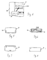
- Fig. 1 is a plan view
- Fig. 2 which is a front view of a terminal table unit 1 embodying this invention
- Fig. 4 for schematically showing its attachment part.
- the terminal table unit 1 has a main body 20 with a terminal table 2, a cassette-connecting connector CN1 and an on-table connector CN3 on its upper surface portion.
- terminal attachment sections 22 formed mutually separated by partitions 21 in its longitudinal direction.
- a positive connection terminal 23, a signal connection terminal 24 and a negative connection terminal 25 are mounted in a row inside each of these terminal attachment sections 22.
- the main body 20 is provided with a display device 7 and a reset switch 8.
- a memory cassette 9 is connected to the cassette-connecting connector CN 1.
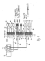
- a control unit 26 which is provided with an insulator interface (IF) 3, a control device 4, a memory device 5 and a display driver 6, as shown in Fig. 3.
- the insulator interface 3 comprises a function of a photo-coupler or the like for isolating the power source and an interface function for guiding input data D0, D1 and D2 (to be explained below) onto an internal bus BU such that the input data D0, D1 and D2 will be electrically isolated and transmitted through the internal bus BU to the control device 4.
- the control device 4 is basically a microprocessor and is adapted to carry out various processes and comparisons, for example, for causing the input data D0, D1 and D2 supplied through the internal bus BU to be stored in the memory device 5 at a specified frequency such as in units of two periods.
- the control device 4 is also adapted so as, when abnormal data are detected, to read out a total of two periods of data, which are one period of the abnormal data stored in the memory device 5 and another period of normal data stored prior to the abnormal data, and to cause them to be stored on the memory medium 10 of the memory cassette 9.
- the control device 4 also serves to supply a start signal SK to the display driver 6 and to thereby start up the display driver 6.
- the control device 4 may further be adapted to compare a two-period portion of the input data D0, D1 and D2 supplied through the internal bus BU with a two-period portion of basic data with specified patterns preliminarily set in the memory device 5 and to judge that the input data are normal or abnormal respectively if they agree or disagree.
- the memory device 5 is also adapted so as, when the control device 4 has detected abnormal data, to transfer a two-period portion of data including one one-period portion of input data including stored abnormal data and another one-period portion of normal input data to the memory medium 10 under the control of the control device 4.
- the display driver 6 is provided both with the function of driving the display device 7 and with the function of a sound driver and is adapted to output a display signal SD to the display device 7 on the basis of the start signal SK supplied from the control device 4.
- the display device 7 comprises a light-emitting diode (LED) and a speaker and is adapted to display abnormal data and to output a vocal message on the abnormality on the basis of the display signal SD supplied from the display driver 6.
- LED light-emitting diode
- the reset switch 8 may comprise a push button and is to be operated upon when it is desired to stop the display and/or the vocal message regarding an abnormal condition by supplying a reset signal JR to the control device 4.
- the memory cassette 9 has a main body 27 provided with a connector CN2 and the memory medium 10 such as an EEPROM connected to the connector CN2.
- the memory medium 10 is for the purpose of storing a total of two-period portion of the input data, that is, a one-period portion of abnormal data from the input data D0, D1 and D2 and another one-period portion of normal data stored prior to the abnormal data.
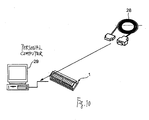
- the memory cassette 9 is portable, when its connector CN2 is removed from the cassette-connecting connector CN1. If a tool cable 28 shown in Fig. 10 is used to connect it to a personal computer 29, time charts of the abnormal and normal data may be displayed on its screen for the analysis of the abnormal data.
- Fig. 9 shows a monitoring system for monitoring a production line by means of a terminal table unit 1 (1-1, 1-2, 1-3, etc.) embodying this invention, together with a PLC (programmable logic controller) 12 serving as a control apparatus, photoelectric switches 30 and proximity switches SW0, SW1, SW2, etc. serving as external input apparatus, and solenoids 31 and valves 32 serving as external output apparatus.
- the PLC 12 is connected to each of the terminal table units 1 by connecting each connector 11 on the part of the PLC 12 to the connector CN3 of each of the terminal table units 1 by means of a cable 33.
- terminal table unit 1 (1-1) is connected to each of photoelectric switches 30 by connecting one end of each of connection cables 34 of the photoelectric switches 30 to the positive connection terminal 23, the signal connection terminal 24 and the negative connection terminal 25 of the terminal table 2.
- the terminal table unit 1 (1-2) is connected to proximity switches SW0, SW1, SW2, etc. by connecting one end of each of connecting cables 35 of the proximity switches SW0, SW1, etc. to the positive connection terminal 23, the signal connection terminal 24 and the negative connection terminal 25 of the terminal table 2.
- the terminal table unit 1 (1-3) is connected to solenoids 31 and valves 32 similarly by connecting one end of each of connecting driver cables 36 and 37 respectively of one of the solenoids 31 and the valves 32 to the positive connection terminal 23, the signal connection terminal 24 and the negative connection terminal 25 of the terminal table 2.
- the terminal table unit 1 receives input data D0, D1 and D2 from the proximity switches SW0, SW1 and SW2 through the connectors 11 of the PLC, these input data D0, D1 and D2 are electrically isolated by the insulation interface 3 and guided through the inner bus BU to the control device 4. These input data D0, D1 and D2 are stored by the control device 4 in the memory device 5 at a specified frequency such as in units of two periods.
- the control device 4 treats the abnormal data F2 as the abnormality trigger T and starts the process of reading out the input data over specified periods including both before and after the occurrence of the abnormality trigger T and causing them to be stored in the memory medium 10 of the memory cassette 9.
- the "specified periods" are the two periods of the input data which are the total of one period including the abnormal data F2 and another period that is one period before the input data belonging to the abnormal data F2 and includes the normal data F1 stored in the memory device 5.
- the control device further serves to compare the two-period portion of the input data D0, D1 and D2 with basic (reference) data with specified patterns preliminarily stored in the memory device 5. If they match, it is concluded that the input data D0, D1 and D2 are normal and if they do not match, the conclusion is that the input data D0, D1 and D2 are abnormal.
- control device 4 operates, upon detecting the abnormal data F2, to supply the start signal SK to the display driver 6 to start up the display driver 6.
- the display driver device 6 serves to output the display signal SD to the display device 7, causing the display device 7 to output the abnormal data F2 by way of display and/or voice and the production line to stop its operations.
- the memory medium 10 of the memory cassette 9 stores a two-period portion of the input data, including a one-period portion of the abnormal data F2 and another one-period portion of the normal data F1.
- the memory cassette 9 is then separated from the terminal table unit 1 by disengaging the connectors CN1 and CN2 from each other and is connected to the personal computer 29 by means of the tool cable 28, as shown in Fig. 10.
- the user can now operate on the personal computer 29 so as to display the time charts of the abnormal data F2 and the normal data F1 stored on the memory medium 10 of the memory cassette 9 on its screen and to thereby analyze the abnormal data F2.
- the part of the production line causing the abnormality is identified and corrected and the operation of the production line is restarted.
- the control unit 26 may be adapted to monitor some other feature of the input data D0, D1 and D2 for the purpose of maintenance.
- the input data D0, D1 and D2 are pulse signals from proximity sensors, being switched on and off.
- the control unit 26 may be adapted to monitor the switch-on frequency (or the number of times a pulse signal is switched on) or the cumulative length of time during which control pulse signal based on the input data is switched on such that the occurrence of an abnormal condition in the production line can be monitored through such maintenance data.
- proximity switches SW0, SW1 and SW2 Although an example with three proximity switches SW0, SW1 and SW2 was described as an example of this invention, the number of proximity switches is not intended to limit the scope of the invention. The invention is equally applicable in the case of photoelectric switches or switches of other kinds such as stop switches.
- the user of this invention can simply remove the memory cassette from main body of the table unit and use a computer or the like to output time charts of the normal and abnormal outputs so as to carry out an analysis of the abnormal data.
- abnormal data can be analyzed and the cause of abnormality can be detected such that the production line or the like can be reliably repaired.
Landscapes
- Physics & Mathematics (AREA)
- General Physics & Mathematics (AREA)
- Engineering & Computer Science (AREA)
- Automation & Control Theory (AREA)
- Health & Medical Sciences (AREA)
- General Health & Medical Sciences (AREA)
- Otolaryngology (AREA)
- Pulmonology (AREA)
- Programmable Controllers (AREA)
- Testing And Monitoring For Control Systems (AREA)
- Automatic Analysis And Handling Materials Therefor (AREA)
- Connections Arranged To Contact A Plurality Of Conductors (AREA)
Abstract
Description
Claims (11)
- A terminal table unit comprising:a main body including a control device; anda memory cassette which includes a memory medium and is detachably attached to said main body;said control device being adapted to receive input data from an input apparatus for controlling an output apparatus and to drive said output apparatus according to said received input data, said control device serving to cause said input data from said input apparatus to be stored on said memory medium.
- The terminal table unit of claim 1 wherein said main body has a connector and said memory cassette is connected to said main body through said connector.
- The terminal table unit of claim 1 wherein said main body further includes a memory device, said control device being adapted to cause said memory device to periodically store new portions of said input data.
- The terminal table unit of claim 3 wherein said memory medium of said cassette stores input data taken in from said memory device.
- The terminal table unit of claim 3 wherein said input data are a periodic signal and said control device is adapted, when abnormal data are detected in said input data, to use said abnormal data as a trigger and to thereby read out from said memory device and cause to be stored on said memory medium a portion of a specified number of periods of said input data including a portion of said input data before said trigger is detected.
- The terminal table unit of claim 5 wherein said specified number of periods of input data includes one period of said abnormal data and one period of said input data before said trigger is detected.
- The terminal table unit of claim 5 wherein said memory device is adapted to store said input data in units of two periods under a control of said control device.
- The terminal table unit of claim 1 wherein said input apparatus includes a PLC connected to a network and switches, said terminal table unit serving as a relay between said PLC and said switches.
- The terminal table unit of claim 1 wherein said control device is adapted to monitor the number of times control signal based on said input data is switched on.
- The terminal table unit of claim 1 wherein said control device is adapted to monitor cumulative length of time during which control signal based on said input data is switched on.
- The terminal table unit of claim 3 wherein said memory device further serves to store basic data with specific patterns and said control device further serves to compare said input data with said basic data.
Applications Claiming Priority (2)
| Application Number | Priority Date | Filing Date | Title |
|---|---|---|---|
| JP2003069469 | 2003-03-14 | ||
| JP2003069469A JP2004280345A (en) | 2003-03-14 | 2003-03-14 | Terminal block device |
Publications (2)
| Publication Number | Publication Date |
|---|---|
| EP1467270A2 true EP1467270A2 (en) | 2004-10-13 |
| EP1467270A3 EP1467270A3 (en) | 2007-09-05 |
Family
ID=32866678
Family Applications (1)
| Application Number | Title | Priority Date | Filing Date |
|---|---|---|---|
| EP04004595A Withdrawn EP1467270A3 (en) | 2003-03-14 | 2004-02-27 | Terminal table unit |
Country Status (5)
| Country | Link |
|---|---|
| US (1) | US7099730B2 (en) |
| EP (1) | EP1467270A3 (en) |
| JP (1) | JP2004280345A (en) |
| KR (2) | KR100656663B1 (en) |
| CN (1) | CN1280744C (en) |
Families Citing this family (2)
| Publication number | Priority date | Publication date | Assignee | Title |
|---|---|---|---|---|
| JP4755949B2 (en) * | 2006-07-28 | 2011-08-24 | 株式会社ミツバ | Control device interface unit and control device interface system |
| JP5223866B2 (en) * | 2007-09-11 | 2013-06-26 | 日本電気株式会社 | Data logger, data storage method and program |
Family Cites Families (12)
| Publication number | Priority date | Publication date | Assignee | Title |
|---|---|---|---|---|
| JPS5955506A (en) * | 1982-09-24 | 1984-03-30 | Sharp Corp | Sequence controller |
| JPS6091753A (en) | 1983-10-26 | 1985-05-23 | Matsushita Electric Ind Co Ltd | Abnormal operation monitoring device |
| US4878176A (en) * | 1984-05-04 | 1989-10-31 | Asics Corporation | Production process control system |
| IT1266491B1 (en) * | 1993-09-13 | 1996-12-30 | Fase Spa | PERFECTED DEVICE FOR WELDING CONTROL. |
| US5461570A (en) * | 1994-06-10 | 1995-10-24 | Johnson & Johnson Vision Products, Inc. | Computer system for quality control correlations |
| KR0156302B1 (en) | 1995-12-21 | 1998-12-15 | 김종진 | The fail data tracing apparatus of rolling mill dc motor thyristor control system |
| JP4394780B2 (en) * | 1999-10-08 | 2010-01-06 | クラリオン株式会社 | Mobile body information recording device |
| JP4345948B2 (en) * | 2000-05-19 | 2009-10-14 | 本田技研工業株式会社 | Motorcycle accident notification system |
| US6701259B2 (en) * | 2000-10-02 | 2004-03-02 | Applied Materials, Inc. | Defect source identifier |
| DE10117459A1 (en) * | 2001-04-06 | 2002-10-24 | Siemens Ag | Method and device for obtaining diagnostic information |
| TWI244603B (en) * | 2001-07-05 | 2005-12-01 | Dainippon Screen Mfg | Substrate processing system for managing device information of substrate processing device |
| JP4071461B2 (en) | 2001-07-05 | 2008-04-02 | 大日本スクリーン製造株式会社 | Substrate processing system, substrate processing apparatus, program, and recording medium |
-
2003
- 2003-03-14 JP JP2003069469A patent/JP2004280345A/en active Pending
-
2004
- 2004-02-27 EP EP04004595A patent/EP1467270A3/en not_active Withdrawn
- 2004-03-11 KR KR1020040016362A patent/KR100656663B1/en not_active Expired - Fee Related
- 2004-03-11 CN CNB2004100283986A patent/CN1280744C/en not_active Expired - Fee Related
- 2004-03-12 US US10/799,929 patent/US7099730B2/en not_active Expired - Lifetime
-
2006
- 2006-07-19 KR KR1020060067165A patent/KR20060090639A/en not_active Withdrawn
Also Published As
| Publication number | Publication date |
|---|---|
| KR100656663B1 (en) | 2006-12-11 |
| CN1530786A (en) | 2004-09-22 |
| EP1467270A3 (en) | 2007-09-05 |
| US7099730B2 (en) | 2006-08-29 |
| US20040233697A1 (en) | 2004-11-25 |
| KR20040081339A (en) | 2004-09-21 |
| CN1280744C (en) | 2006-10-18 |
| KR20060090639A (en) | 2006-08-14 |
| JP2004280345A (en) | 2004-10-07 |
Similar Documents
| Publication | Publication Date | Title |
|---|---|---|
| EP1705539B1 (en) | Emergency-stop device | |
| JP4835842B2 (en) | IO unit in a building block type safety controller | |
| EP0603395B1 (en) | Fluid pressure apparatus | |
| CN204613616U (en) | manipulation equipment | |
| JP4277656B2 (en) | Door drive control device | |
| CN110073057A (en) | The monitoring system of foreign matter removal device, foreign matter remove the monitoring method of system and foreign matter removal device | |
| TWI728874B (en) | Encoder system, motor system and robot | |
| KR20090100580A (en) | Redundancy Device of Controller | |
| JPH0296201A (en) | Abnormality restoring device for sequence control system machine | |
| CN112938681A (en) | Electronic test node for automatic checking of safety chains | |
| JP2004266994A (en) | Inverter device | |
| US7099730B2 (en) | Terminal table unit | |
| JP3997529B2 (en) | Vehicle failure diagnosis method | |
| JP2007061819A (en) | Multiple probe power feed system and method for ultrasonic welding | |
| JP7339614B2 (en) | Actuator controller | |
| JP2004010200A (en) | Signal switching method for elevator | |
| JP2010191875A (en) | Voice information system of abnormality of contact system in programmable controller | |
| JP2007083967A (en) | Erroneous work prevention system in manufacturing step | |
| JP5999007B2 (en) | Equipment status monitoring device and monitoring method | |
| JPH0784635A (en) | Retry monitor for production line sequence controller | |
| JPWO2009028016A1 (en) | Slave station terminals that can display addresses | |
| JP2021127044A (en) | Breaker drive unit monitoring device | |
| JP2008282066A (en) | Failure notification relay | |
| JPH11346240A (en) | Hub device | |
| JPH09307973A (en) | Remote monitoring controller |
Legal Events
| Date | Code | Title | Description |
|---|---|---|---|
| PUAI | Public reference made under article 153(3) epc to a published international application that has entered the european phase |
Free format text: ORIGINAL CODE: 0009012 |
|
| AK | Designated contracting states |
Kind code of ref document: A2 Designated state(s): AT BE BG CH CY CZ DE DK EE ES FI FR GB GR HU IE IT LI LU MC NL PT RO SE SI SK TR |
|
| AX | Request for extension of the european patent |
Extension state: AL LT LV MK |
|
| PUAL | Search report despatched |
Free format text: ORIGINAL CODE: 0009013 |
|
| AK | Designated contracting states |
Kind code of ref document: A3 Designated state(s): AT BE BG CH CY CZ DE DK EE ES FI FR GB GR HU IE IT LI LU MC NL PT RO SE SI SK TR |
|
| AX | Request for extension of the european patent |
Extension state: AL LT LV MK |
|
| 17P | Request for examination filed |
Effective date: 20080228 |
|
| 17Q | First examination report despatched |
Effective date: 20080328 |
|
| AKX | Designation fees paid |
Designated state(s): DE FR GB IT |
|
| STAA | Information on the status of an ep patent application or granted ep patent |
Free format text: STATUS: THE APPLICATION HAS BEEN WITHDRAWN |
|
| 18W | Application withdrawn |
Effective date: 20110210 |