EP1467244B1 - Zubehörkoffer für Kamera - Google Patents
Zubehörkoffer für Kamera Download PDFInfo
- Publication number
- EP1467244B1 EP1467244B1 EP03252164A EP03252164A EP1467244B1 EP 1467244 B1 EP1467244 B1 EP 1467244B1 EP 03252164 A EP03252164 A EP 03252164A EP 03252164 A EP03252164 A EP 03252164A EP 1467244 B1 EP1467244 B1 EP 1467244B1
- Authority
- EP
- European Patent Office
- Prior art keywords
- camera
- plate
- anchoring
- accessory case
- casing body
- Prior art date
- Legal status (The legal status is an assumption and is not a legal conclusion. Google has not performed a legal analysis and makes no representation as to the accuracy of the status listed.)
- Expired - Lifetime
Links
- 238000004873 anchoring Methods 0.000 claims abstract description 41
- 230000002093 peripheral effect Effects 0.000 claims abstract description 21
- 238000010276 construction Methods 0.000 description 1
- 230000002452 interceptive effect Effects 0.000 description 1
- 230000000284 resting effect Effects 0.000 description 1
Images




Classifications
-
- A—HUMAN NECESSITIES
- A45—HAND OR TRAVELLING ARTICLES
- A45C—PURSES; LUGGAGE; HAND CARRIED BAGS
- A45C11/00—Receptacles for purposes not provided for in groups A45C1/00-A45C9/00
- A45C11/38—Camera cases, e.g. of ever-ready type
-
- G—PHYSICS
- G03—PHOTOGRAPHY; CINEMATOGRAPHY; ANALOGOUS TECHNIQUES USING WAVES OTHER THAN OPTICAL WAVES; ELECTROGRAPHY; HOLOGRAPHY
- G03B—APPARATUS OR ARRANGEMENTS FOR TAKING PHOTOGRAPHS OR FOR PROJECTING OR VIEWING THEM; APPARATUS OR ARRANGEMENTS EMPLOYING ANALOGOUS TECHNIQUES USING WAVES OTHER THAN OPTICAL WAVES; ACCESSORIES THEREFOR
- G03B17/00—Details of cameras or camera bodies; Accessories therefor
- G03B17/56—Accessories
Definitions
- the invention relates to a camera accessory case, more particularly to a camera accessory case adapted to be mounted on a camera connecting plate of a camera stand.
- a camera accessory holder 11 on a camera stand 13 which supports a camera 14 thereon, as best shown in Figure 1.
- the holder 11 is mounted on the camera stand 13 with the use of a support frame 12 such that the holder 11 is disposed at the front side of the camera stand 13 , i.e., the direction of the lens of the camera 14.
- the holder 11 is formed with a plurality of receiving spaces to receive different camera accessories therein.
- a camera support 131 of the camera stand 13 is pivotable to adjust tilting angle of the camera 14 in different directions. The holder 11 remains still during tilt adjustment of the camera support 131.
- the aforesaid camera accessory holder 11 is disadvantageous in that, when the camera 14 is operated to tilt forwardly, the lens of the camera 14 might collide with the camera accessories on the holder 11.
- the holder 11 thus interferes with the movement of the camera 14 on the camera stand 13, which necessitates dismounting of the holder 11 and which inconveniences the film-making personnel.
- the object of the present invention is to provide a camera accessory case that can be used to store camera accessories therein and that is clear of the aforesaid drawback associated with the conventional camera accessory holder.
- the camera accessory case of the present invention is adapted to be mounted on a camera connecting plate of a camera stand, and comprises a casing body and an anchoring unit.
- the casing body has a bottom wall and a peripheral wall extending upwardly from a periphery of the bottom wall.
- the bottom wall and the peripheral wall cooperate to confine an accessory receiving space that has a top opening.
- the casing body has a casing axis transverse to the bottom wall.
- the anchoring unit has a plate connecting portion adapted to be mounted fixedly on the camera connecting plate, and a casing connecting portion connected pivotally to the plate connecting portion and further connected to the peripheral wall of the casing body such that the casing axis can be disposed in an upright position even when the camera connectingplate is tilted.
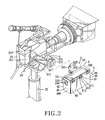
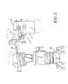
- the bottom side of a camera 21 is connected to a camera connecting plate 23 to permit mounting of the camera 21 on a camera stand 22. Since the position of the camera accessory case 3 of this invention should not interfere with tilting operations of the camera 21, the camera accessory case 3 is mounted on the camera connecting plate 23 or on top of the camera stand 22 and is disposed adjacent to the left or right lateral side of the camera 21. For the sake of illustration, the camera accessory case 3 of this invention is shown in the drawings to be disposed adjacent to the right lateral side 211 of the camera 21. It is also noted that the bottom side of the camera 21 is usually formed with a groove 212 that permits resting of the camera 21 on a shoulder of a cameraman.
- the camera accessory case 3 of this invention is preferably adapted to be mounted in the space between the camera 21 and the camera connecting plate 23 for convenience in design and for efficient utilization of space.
- the preferred embodiment of the camera accessory case 3 includes a casing body 4, an anchoring unit 5 and a lid 6.
- the casing body 4 includes a bottom wall 41 and a peripheral wall 40 extending upwardly from a periphery of the bottom wall 41.
- the bottom wall 41 and the peripheral wall 40 cooperate to confine an accessory receiving space 400 that has a top opening.
- the accessory receiving space 400 may be partitioned into a plurality of compartments (not shown) for receiving different camera accessories (not shown) therein.
- the casing body 4 has a casing axis transverse to the bottom wall 41.
- the bottom wall 41 is rectangular
- the peripheral wall 40 includes a left upright wall portion 42, a right upright wall portion 43, a front upright wall portion 44, and a rear upright wall portion 45.
- the lid 6 serves to cover the top opening of the accessory receiving space 400.
- Hinges 61 interconnect pivotally the lid 6 and the peripheral wall 40.
- the hinges 61 are preferably mounted on an outer top edge of one of the wall portions 42, 43, 44, 45 that is farthest from the camera 21 and the camera stand 22.
- the hinges 61 are preferably mounted on the right upright wall portion 43.
- the lid 6 has a flat surface 62 that faces upwardly when the lid 6 is pivoted to an uncovering position.
- Each hinge 61 includes first and second hinge leaves 612, 613 connected respectively to the lid 6 and the right upright wall portion 43 of the peripheral wall 40, and a hinge pin 611 interconnecting the first and second hinge leaves 612, 613.
- the first and second hinge leaves 612, 613 cooperate to support the lid 6 at the uncovering position.
- the first hinge leaf 612 abuts against the second hinge leaf 613 when the lid 6 is at the uncovering position so that the flat surface 62 of the lid 6, which is made of a material of sufficient hardness, can serve as a writing support.
- the anchoring unit 5 includes first and second anchoring plates 51, 52, which constitute a plate connecting portion that is adapted to be mounted fixedly on the camera connecting plate 23, and an anchoring frame 53, which serves as a casing connecting portion that is connected pivotally to the plate connecting portion and that is further connected to the peripheral wall 40 of the casing body 4 such that the casing axis can be disposed in an upright position even when the camera connecting plate 23 is tilted.
- the first anchoringplate 51 extends ina longitudinal direction and has a first end 511 that is adapted to be mounted fixedly on the camera connecting plate 23 so as to be disposed in the space between the camera 21 and the camera connecting plate 23, and a second end 512 opposite to the first end 511 in the longitudinal direction. Accordingly, the second end 512 of the first anchoring plate 51 projects relative to the right lateral side 211 of the camera 21.
- the second anchoring plate 52 has a first plate end 521 connected to the second end 512 of the first anchoring plate 51, and a second plate end 522 connected pivotally to the anchoring frame 53.
- the second plate end 522 is spaced apart from the first plate end 521 along a transverse direction that is transverse to the longitudinal direction of the first anchoring plate 51.
- the anchoring frame 53 of this embodiment includes a first arm 531 that has a middle segment connected pivotally to the second plate end 522 of the second anchoring plate 52 and that is disposed adjacent to the left upright wall portion 42, and second and third arms 532, 533 that extend transversely from opposite ends of the first arm 531 and that are connected pivotally and respectively to the front and rear upright wall portions 44, 45 of the peripheral wall 40 of the casing body 4 adjacent to the top opening of the accessory receiving space 400 .
- the first arm 531 is slightly longer than the length of the casing body 4, i.e. , the distance between the front and rear upright wall portions 44, 45.
- the lengths of the second and third arms 532, 533 are equal and are shorter than the width of the casing body 4, i.e., the distance between the left and right upright wall portions 42, 43.
- the anchoring unit 5 further includes a releasable locking member 534, in the form of a wing nut, for arresting selectively pivoting movement of the third arm 533, and thus the anchoring frame 53, relative to the peripheral wall 40 of the casing body 4.
- a releasable locking member (not shown) may be employed to act on the second arm 532 in a similar manner.
- the anchoring unit 5 further includes a releasable fastening unit 513 for interconnecting releasably and non-rotatably the first plate end 521 of the second anchoring plate 52 and the second end 512 of the first anchoring plate 51.
- the fastening unit 513 is conventional in construction, is mounted on the second end 512 of the first anchoring plate 51, and engages releasably an engaging hole 523 formed in the first plate end 521 of the second anchoring plate 52. Due to the fastening unit 513, the casing body 4 can be mounted and dismounted with relative ease.
- the plate connecting portion of the anchoring unit 5 is split into the first and second anchoring plates 51, 52 for the purpose of convenience when mounting and dismounting the casing body 4.
- weight can be added to the bottom wall 41 of the casing body 4 to avoid unforced swaying of the casing body 4.
- the camera accessory case 3 of this invention is designed to prevent collision with the camera 21 when adjusting tilt of the latter, and has a casing body 4 with a casing axis that can be disposed in the upright position to ensure that items do not spill out of the casing body 4 even when the camera connecting plate 23 is tilted.
- the lid 6 of the camera accessory case 3 can further serve as a writing support when disposed at the uncovering position.
Landscapes
- Physics & Mathematics (AREA)
- General Physics & Mathematics (AREA)
- Studio Devices (AREA)
- Purses, Travelling Bags, Baskets, Or Suitcases (AREA)
- Accessories Of Cameras (AREA)
- Packages (AREA)
Claims (11)
- Kamerazubehörbehälter (3), der angepasst ist, um an einer Kameraverbindungsplatte (23) eines Kamerastativs (22) angebracht zu werden, gekennzeichnet durch:einen Gehäusekörper (4), der eine Unterseiten- bzw. Bodenwand (41) und eine periphere bzw. Umfangswand (40) hat, die sich von einem Umfang der Unterseiten- bzw. Bodenwand (41) nach oben erstreckt, wobei die Unterseiten- bzw. Bodenwand (41) und die periphere bzw. Umfangswand (40) dazu beitragen bzw. zusammenwirken, um einen Zubehöraufnahmeplatz bzw. -raum (400) zu begrenzen, der eine obere Öffnung hat, wobei der Gehäusekörper (4) eine Gehäuseachse quer zu der Unterseiten- bzw. Bodenwand (41) hat; undeine Verankerungseinheit (5), die einen Plattenverbindungsteil, der angepasst ist, um fest an der Kameraverbindungsplatte (23) angebracht zu werden, und einen Gehäuseverbindungsteil hat, der gelenkig bzw. schwenkbar mit dem Plattenverbindungsteil verbunden ist und ferner mit der peripheren bzw. Umfangswand (40) des Gehäusekörpers (4) derart verbunden ist, dass die Gehäuseachse in einer aufrechten bzw. senkrechten Position angeordnet werden kann, sogar wenn die Kameraverbindungsplatte (23) geneigt ist.
- Kamerazubehörbehälter (3), wie in Anspruch 1 beansprucht, dadurch gekennzeichnet, dass die Verankerungseinheit (5) einen Verankerungsrahmen (53) enthält, welcher als der Gehäuseverbindungsabschnitt dient, wobei der Verankerungsrahmen (53) einen ersten Arm (531), der gelenkig bzw. schwenkbar mit dem Plattenverbindungsteil verbunden ist, und zweite und dritte Arme (532, 533) enthält, welche sich quer von entgegengesetzten Enden des ersten Armes (531) erstrecken und welche mit der peripheren bzw. Umfangswand (40) des Gehäusekörpers (4) verbunden sind.
- Kamerazubehörbehälter (3), wie in Anspruch 2 beansprucht, ferner dadurch gekennzeichnet, dass die zweiten und dritten Arme (532, 533) gelenkig bzw. schwenkbar mit der peripheren bzw. Umfangswand (40) verbunden sind, angrenzend an die obere Öffnung des Zubehöraufnahmeplatzes bzw. -raumes (400).
- Kamerazubehörbehälter (3), wie in Anspruch 2 beansprucht, ferner dadurch gekennzeichnet, dass der erste Arm (531) einen mittleren Abschnitt hat, der gelenkig bzw. schwenkbar mit dem Plattenverbindungsteil verbunden ist.
- Kamerazubehörbehälter (3), wie in Anspruch 2 beansprucht, ferner dadurch gekennzeichnet, dass die Unterseiten- bzw. Bodenwand (41) des Gehäusekörpers (4) rechteckig ist, und die periphere bzw. Umfangswand (40) einen linken aufrechten bzw. senkrechten Wandteil (42), einen rechten aufrechten bzw. senkrechten Wandteil (43), einen vorderen aufrechten bzw. senkrechten Wandteil (44) und einen hinteren aufrechten bzw. senkrechten Wandteil (45) enthält, wobei die zweiten und dritten Arme (532, 533) gelenkig bzw. schwenkbar und jeweils mit den vorderen und hinteren aufrechten bzw. senkrechten Wandteilen (44, 45) verbunden sind, wobei der erste Arm (531) angrenzend an eines der linken und der rechten aufrechten bzw. senkrechten Wandteile (42, 43) angeordnet ist.
- Kamerazubehörbehälter (3), wie in Anspruch 5 beansprucht, dadurch gekennzeichnet, dass die Verankerungseinheit (5) ferner ein lösbares Sicherungs- bzw. Verriegelungsglied (534) zum wahlweisen Feststellen bzw. Arretieren der Schwenkbewegung von einem der zweiten und dritten Arme (532, 533) relativ zu der peripheren bzw. Umfangswand (40) des Gehäusekörpers (4) enthält.
- Kamerazubehörbehälter (3), wie in Anspruch 2 beansprucht, dadurch gekennzeichnet, dass die Verankerungseinheit (5) ferner erste und zweite Verankerungsplatten (51, 52) enthält, die den Plattenverbindungsteil bilden, wobei sich die erste Verankerungsplatte (51) in einer Längsrichtung erstreckt und ein erstes Ende (511), das angepasst ist, um fest an der Kameraverbindungsplatte (23) angebracht zu werden, und ein zweites Ende (512) hat, das entgegengesetzt zu dem ersten Ende (511) in der Längsrichtung ist, wobei die zweite Verankerungsplatte (52) ein erstes Plattenende (521), dass mit dem zweiten Ende (512) der ersten Verankerungsplatte (51) verbunden ist, und ein zweites Plattenende (522) hat, das gelenkig bzw. schwenkbar mit dem ersten Arm (531) verbunden ist.
- Kamerazubehörbehälter (3), wie in Anspruch 7 beansprucht, ferner dadurch gekennzeichnet, dass das zweite Plattenende (522) von dem ersten Plattenende (521) entlang einer Querrichtung beabstandet ist, die quer zu der Längsrichtung ist.
- Kamerazubehörbehälter (3), wie in Anspruch 7 beansprucht, dadurch gekennzeichnet, dass die Verankerungseinheit (5) ferner eine lösbare Befestigungseinheit (513) zum lösbaren und nicht drehbaren Verbinden des ersten Plattenendes (521) der zweiten Verankerungsplatte (52) und des zweiten Endes (512) der ersten Verankerungsplatte (51) miteinander enthält.
- Kamerazubehörbehälter (3), wie in Anspruch 5 beansprucht, ferner gekennzeichnet durch einen Deckel (6) zum Bedecken der oberen Öffnung des Zubehöraufnahmeplatzes bzw. -raumes (400), und ein Scharnier (61) zum gelenkigen bzw. schwenkbaren Verbinden des Deckels (6) und des anderen einen der linken und rechten aufrechten bzw. senkrechten Wandteile (42, 43) miteinander.
- Kamerazubehörbehälter (3), wie in Anspruch 10 beansprucht, ferner dadurch gekennzeichnet, dass der Deckel (6) eine flache bzw. ebene Oberfläche (62) hat, die nach oben gerichtet ist, wenn der Deckel (6) in eine nicht abgedeckte Position geschwenkt ist, wobei das Scharnier (61) erste und zweite Scharnierblätter bzw. -flügel (612, 613) enthält, die jeweils mit dem Deckel (6) und der peripheren bzw. Umfangswand (40) des Gehäusekörpers (4) verbunden sind, und wobei ein Scharnierstift bzw. -zapfen (611) die ersten und zweiten Scharnierblätter bzw. -flügel (612, 613) miteinander verbindet, wobei die ersten und zweiten Scharnierblätter bzw. -flügel (612, 613) dazu beitragen bzw. zusammenwirken, um den Deckel (6) in der unabgedeckten Position zu tragen bzw. stützen.
Priority Applications (4)
| Application Number | Priority Date | Filing Date | Title |
|---|---|---|---|
| AT03252164T ATE306682T1 (de) | 2003-04-04 | 2003-04-04 | Zubehörkoffer für kamera |
| DE60301857T DE60301857T2 (de) | 2003-04-04 | 2003-04-04 | Zubehörkoffer für Kamera |
| EP03252164A EP1467244B1 (de) | 2003-04-04 | 2003-04-04 | Zubehörkoffer für Kamera |
| ES03252164T ES2250835T3 (es) | 2003-04-04 | 2003-04-04 | Caja para accesorio de camara. |
Applications Claiming Priority (1)
| Application Number | Priority Date | Filing Date | Title |
|---|---|---|---|
| EP03252164A EP1467244B1 (de) | 2003-04-04 | 2003-04-04 | Zubehörkoffer für Kamera |
Publications (2)
| Publication Number | Publication Date |
|---|---|
| EP1467244A1 EP1467244A1 (de) | 2004-10-13 |
| EP1467244B1 true EP1467244B1 (de) | 2005-10-12 |
Family
ID=32865068
Family Applications (1)
| Application Number | Title | Priority Date | Filing Date |
|---|---|---|---|
| EP03252164A Expired - Lifetime EP1467244B1 (de) | 2003-04-04 | 2003-04-04 | Zubehörkoffer für Kamera |
Country Status (4)
| Country | Link |
|---|---|
| EP (1) | EP1467244B1 (de) |
| AT (1) | ATE306682T1 (de) |
| DE (1) | DE60301857T2 (de) |
| ES (1) | ES2250835T3 (de) |
Families Citing this family (1)
| Publication number | Priority date | Publication date | Assignee | Title |
|---|---|---|---|---|
| CN102486599A (zh) * | 2011-11-11 | 2012-06-06 | 深圳市迪比科电子科技有限公司 | 相机复合型脚架 |
Family Cites Families (4)
| Publication number | Priority date | Publication date | Assignee | Title |
|---|---|---|---|---|
| US3863945A (en) * | 1973-09-04 | 1975-02-04 | Diane M Dunstan | Wheel unit for attachment to a tripod |
| US5433358A (en) * | 1993-09-06 | 1995-07-18 | Millard; Trevor | Tripods |
| US5651455A (en) * | 1996-07-17 | 1997-07-29 | Garcia; Marjorie | Utility accessory bag |
| GB9727043D0 (en) * | 1997-12-23 | 1998-02-18 | Cripps Christopher S | Camera hammock |
-
2003
- 2003-04-04 EP EP03252164A patent/EP1467244B1/de not_active Expired - Lifetime
- 2003-04-04 DE DE60301857T patent/DE60301857T2/de not_active Expired - Fee Related
- 2003-04-04 ES ES03252164T patent/ES2250835T3/es not_active Expired - Lifetime
- 2003-04-04 AT AT03252164T patent/ATE306682T1/de not_active IP Right Cessation
Also Published As
| Publication number | Publication date |
|---|---|
| ES2250835T3 (es) | 2006-04-16 |
| DE60301857T2 (de) | 2006-06-22 |
| ATE306682T1 (de) | 2005-10-15 |
| EP1467244A1 (de) | 2004-10-13 |
| DE60301857D1 (de) | 2006-02-23 |
Similar Documents
| Publication | Publication Date | Title |
|---|---|---|
| US6822857B2 (en) | Monitor improved in a tilting structure | |
| US6336413B1 (en) | Talegate table | |
| US4577788A (en) | Portable multipurpose desk container | |
| KR102565552B1 (ko) | 스탠드 및 이를 구비한 디스플레이 장치 | |
| US6592090B1 (en) | Object supporting structure | |
| USD349640S (en) | Wall mountable support bracket | |
| US20020056794A1 (en) | Stand for reading material | |
| US20120275102A1 (en) | Bag computer display panel frame | |
| US11172761B2 (en) | Vehicle door storage unit | |
| US5267716A (en) | Mount for magnifying lens | |
| US7595978B2 (en) | Flat panel display with universal rotation | |
| JPH11338576A (ja) | 液晶ディスプレイ支持装置 | |
| US7861992B2 (en) | Wall-mount support | |
| US10538201B2 (en) | Interior prismatic mirror with integral toggle | |
| US20090256035A1 (en) | Instrument-mounting head with balance control | |
| EP1467244A1 (de) | Zubehörkoffer für Kamera | |
| US20040223754A1 (en) | Camera accessory case | |
| US20090263118A1 (en) | Camera-mounting head with balance control | |
| US7740222B2 (en) | Electronic device with a hanging mechanism | |
| US5913491A (en) | Paper roll holder | |
| CA2642418A1 (en) | Articulating support mechanism with pivotal brake shoe | |
| US20240051472A1 (en) | Angularly adjustable object support rack for a vehicle | |
| US7748676B2 (en) | Wall-mount support with cable accommodating capability | |
| US20080049343A1 (en) | Vehicle mirror assembly with reduced mirror shaking | |
| CN117137296A (zh) | 一种多功能的智能镜 |
Legal Events
| Date | Code | Title | Description |
|---|---|---|---|
| PUAI | Public reference made under article 153(3) epc to a published international application that has entered the european phase |
Free format text: ORIGINAL CODE: 0009012 |
|
| 17P | Request for examination filed |
Effective date: 20031031 |
|
| AK | Designated contracting states |
Kind code of ref document: A1 Designated state(s): AT BE BG CH CY CZ DE DK EE ES FI FR GB GR HU IE IT LI LU MC NL PT RO SE SI SK TR |
|
| AX | Request for extension of the european patent |
Extension state: AL LT LV MK |
|
| GRAP | Despatch of communication of intention to grant a patent |
Free format text: ORIGINAL CODE: EPIDOSNIGR1 |
|
| AKX | Designation fees paid |
Designated state(s): AT BE BG CH CY CZ DE DK EE ES FI FR GB GR HU IE IT LI LU MC NL PT RO SE SI SK TR |
|
| GRAS | Grant fee paid |
Free format text: ORIGINAL CODE: EPIDOSNIGR3 |
|
| GRAA | (expected) grant |
Free format text: ORIGINAL CODE: 0009210 |
|
| AK | Designated contracting states |
Kind code of ref document: B1 Designated state(s): AT BE BG CH CY CZ DE DK EE ES FI FR GB GR HU IE IT LI LU MC NL PT RO SE SI SK TR |
|
| PG25 | Lapsed in a contracting state [announced via postgrant information from national office to epo] |
Ref country code: SK Free format text: LAPSE BECAUSE OF FAILURE TO SUBMIT A TRANSLATION OF THE DESCRIPTION OR TO PAY THE FEE WITHIN THE PRESCRIBED TIME-LIMIT Effective date: 20051012 Ref country code: BE Free format text: LAPSE BECAUSE OF FAILURE TO SUBMIT A TRANSLATION OF THE DESCRIPTION OR TO PAY THE FEE WITHIN THE PRESCRIBED TIME-LIMIT Effective date: 20051012 Ref country code: AT Free format text: LAPSE BECAUSE OF FAILURE TO SUBMIT A TRANSLATION OF THE DESCRIPTION OR TO PAY THE FEE WITHIN THE PRESCRIBED TIME-LIMIT Effective date: 20051012 Ref country code: CZ Free format text: LAPSE BECAUSE OF FAILURE TO SUBMIT A TRANSLATION OF THE DESCRIPTION OR TO PAY THE FEE WITHIN THE PRESCRIBED TIME-LIMIT Effective date: 20051012 Ref country code: LI Free format text: LAPSE BECAUSE OF FAILURE TO SUBMIT A TRANSLATION OF THE DESCRIPTION OR TO PAY THE FEE WITHIN THE PRESCRIBED TIME-LIMIT Effective date: 20051012 Ref country code: CH Free format text: LAPSE BECAUSE OF FAILURE TO SUBMIT A TRANSLATION OF THE DESCRIPTION OR TO PAY THE FEE WITHIN THE PRESCRIBED TIME-LIMIT Effective date: 20051012 Ref country code: FI Free format text: LAPSE BECAUSE OF FAILURE TO SUBMIT A TRANSLATION OF THE DESCRIPTION OR TO PAY THE FEE WITHIN THE PRESCRIBED TIME-LIMIT Effective date: 20051012 Ref country code: SI Free format text: LAPSE BECAUSE OF FAILURE TO SUBMIT A TRANSLATION OF THE DESCRIPTION OR TO PAY THE FEE WITHIN THE PRESCRIBED TIME-LIMIT Effective date: 20051012 Ref country code: RO Free format text: LAPSE BECAUSE OF FAILURE TO SUBMIT A TRANSLATION OF THE DESCRIPTION OR TO PAY THE FEE WITHIN THE PRESCRIBED TIME-LIMIT Effective date: 20051012 Ref country code: NL Free format text: LAPSE BECAUSE OF FAILURE TO SUBMIT A TRANSLATION OF THE DESCRIPTION OR TO PAY THE FEE WITHIN THE PRESCRIBED TIME-LIMIT Effective date: 20051012 |
|
| REG | Reference to a national code |
Ref country code: GB Ref legal event code: FG4D |
|
| REG | Reference to a national code |
Ref country code: CH Ref legal event code: EP |
|
| REG | Reference to a national code |
Ref country code: IE Ref legal event code: FG4D |
|
| PG25 | Lapsed in a contracting state [announced via postgrant information from national office to epo] |
Ref country code: BG Free format text: LAPSE BECAUSE OF FAILURE TO SUBMIT A TRANSLATION OF THE DESCRIPTION OR TO PAY THE FEE WITHIN THE PRESCRIBED TIME-LIMIT Effective date: 20060112 Ref country code: SE Free format text: LAPSE BECAUSE OF FAILURE TO SUBMIT A TRANSLATION OF THE DESCRIPTION OR TO PAY THE FEE WITHIN THE PRESCRIBED TIME-LIMIT Effective date: 20060112 Ref country code: GR Free format text: LAPSE BECAUSE OF FAILURE TO SUBMIT A TRANSLATION OF THE DESCRIPTION OR TO PAY THE FEE WITHIN THE PRESCRIBED TIME-LIMIT Effective date: 20060112 Ref country code: DK Free format text: LAPSE BECAUSE OF FAILURE TO SUBMIT A TRANSLATION OF THE DESCRIPTION OR TO PAY THE FEE WITHIN THE PRESCRIBED TIME-LIMIT Effective date: 20060112 |
|
| REF | Corresponds to: |
Ref document number: 60301857 Country of ref document: DE Date of ref document: 20060223 Kind code of ref document: P |
|
| PG25 | Lapsed in a contracting state [announced via postgrant information from national office to epo] |
Ref country code: PT Free format text: LAPSE BECAUSE OF FAILURE TO SUBMIT A TRANSLATION OF THE DESCRIPTION OR TO PAY THE FEE WITHIN THE PRESCRIBED TIME-LIMIT Effective date: 20060313 |
|
| NLV1 | Nl: lapsed or annulled due to failure to fulfill the requirements of art. 29p and 29m of the patents act | ||
| PG25 | Lapsed in a contracting state [announced via postgrant information from national office to epo] |
Ref country code: IE Free format text: LAPSE BECAUSE OF NON-PAYMENT OF DUE FEES Effective date: 20060404 |
|
| PG25 | Lapsed in a contracting state [announced via postgrant information from national office to epo] |
Ref country code: HU Free format text: LAPSE BECAUSE OF FAILURE TO SUBMIT A TRANSLATION OF THE DESCRIPTION OR TO PAY THE FEE WITHIN THE PRESCRIBED TIME-LIMIT Effective date: 20060413 |
|
| REG | Reference to a national code |
Ref country code: ES Ref legal event code: FG2A Ref document number: 2250835 Country of ref document: ES Kind code of ref document: T3 |
|
| PGFP | Annual fee paid to national office [announced via postgrant information from national office to epo] |
Ref country code: ES Payment date: 20060424 Year of fee payment: 4 |
|
| PGFP | Annual fee paid to national office [announced via postgrant information from national office to epo] |
Ref country code: FR Payment date: 20060425 Year of fee payment: 4 |
|
| REG | Reference to a national code |
Ref country code: CH Ref legal event code: PL |
|
| PG25 | Lapsed in a contracting state [announced via postgrant information from national office to epo] |
Ref country code: MC Free format text: LAPSE BECAUSE OF NON-PAYMENT OF DUE FEES Effective date: 20060430 |
|
| PGFP | Annual fee paid to national office [announced via postgrant information from national office to epo] |
Ref country code: IT Payment date: 20060430 Year of fee payment: 4 |
|
| PGFP | Annual fee paid to national office [announced via postgrant information from national office to epo] |
Ref country code: DE Payment date: 20060531 Year of fee payment: 4 |
|
| ET | Fr: translation filed | ||
| PLBE | No opposition filed within time limit |
Free format text: ORIGINAL CODE: 0009261 |
|
| STAA | Information on the status of an ep patent application or granted ep patent |
Free format text: STATUS: NO OPPOSITION FILED WITHIN TIME LIMIT |
|
| 26N | No opposition filed |
Effective date: 20060713 |
|
| REG | Reference to a national code |
Ref country code: IE Ref legal event code: MM4A |
|
| GBPC | Gb: european patent ceased through non-payment of renewal fee |
Effective date: 20070404 |
|
| PG25 | Lapsed in a contracting state [announced via postgrant information from national office to epo] |
Ref country code: DE Free format text: LAPSE BECAUSE OF NON-PAYMENT OF DUE FEES Effective date: 20071101 |
|
| PG25 | Lapsed in a contracting state [announced via postgrant information from national office to epo] |
Ref country code: GB Free format text: LAPSE BECAUSE OF NON-PAYMENT OF DUE FEES Effective date: 20070404 |
|
| PG25 | Lapsed in a contracting state [announced via postgrant information from national office to epo] |
Ref country code: EE Free format text: LAPSE BECAUSE OF FAILURE TO SUBMIT A TRANSLATION OF THE DESCRIPTION OR TO PAY THE FEE WITHIN THE PRESCRIBED TIME-LIMIT Effective date: 20051012 |
|
| REG | Reference to a national code |
Ref country code: ES Ref legal event code: FD2A Effective date: 20070407 |
|
| PG25 | Lapsed in a contracting state [announced via postgrant information from national office to epo] |
Ref country code: TR Free format text: LAPSE BECAUSE OF FAILURE TO SUBMIT A TRANSLATION OF THE DESCRIPTION OR TO PAY THE FEE WITHIN THE PRESCRIBED TIME-LIMIT Effective date: 20051012 Ref country code: FR Free format text: LAPSE BECAUSE OF NON-PAYMENT OF DUE FEES Effective date: 20070430 Ref country code: LU Free format text: LAPSE BECAUSE OF NON-PAYMENT OF DUE FEES Effective date: 20060404 |
|
| PG25 | Lapsed in a contracting state [announced via postgrant information from national office to epo] |
Ref country code: ES Free format text: LAPSE BECAUSE OF NON-PAYMENT OF DUE FEES Effective date: 20070407 |
|
| PG25 | Lapsed in a contracting state [announced via postgrant information from national office to epo] |
Ref country code: CY Free format text: LAPSE BECAUSE OF FAILURE TO SUBMIT A TRANSLATION OF THE DESCRIPTION OR TO PAY THE FEE WITHIN THE PRESCRIBED TIME-LIMIT Effective date: 20051012 |
|
| PG25 | Lapsed in a contracting state [announced via postgrant information from national office to epo] |
Ref country code: IT Free format text: LAPSE BECAUSE OF NON-PAYMENT OF DUE FEES Effective date: 20070404 |