EP1467186A2 - Optical encoder with resinous code plate - Google Patents
Optical encoder with resinous code plate Download PDFInfo
- Publication number
- EP1467186A2 EP1467186A2 EP04008376A EP04008376A EP1467186A2 EP 1467186 A2 EP1467186 A2 EP 1467186A2 EP 04008376 A EP04008376 A EP 04008376A EP 04008376 A EP04008376 A EP 04008376A EP 1467186 A2 EP1467186 A2 EP 1467186A2
- Authority
- EP
- European Patent Office
- Prior art keywords
- surface area
- code
- track
- molded
- resinous
- Prior art date
- Legal status (The legal status is an assumption and is not a legal conclusion. Google has not performed a legal analysis and makes no representation as to the accuracy of the status listed.)
- Granted
Links
- 230000003287 optical effect Effects 0.000 title claims abstract description 32
- 239000012260 resinous material Substances 0.000 claims description 77
- 230000001788 irregular Effects 0.000 claims description 70
- 238000000465 moulding Methods 0.000 claims description 35
- 238000011144 upstream manufacturing Methods 0.000 claims description 11
- 230000001747 exhibiting effect Effects 0.000 claims description 5
- 238000007493 shaping process Methods 0.000 description 57
- 239000011347 resin Substances 0.000 description 25
- 229920005989 resin Polymers 0.000 description 25
- 238000000034 method Methods 0.000 description 15
- 230000008569 process Effects 0.000 description 14
- 239000011295 pitch Substances 0.000 description 12
- 230000008859 change Effects 0.000 description 7
- 230000009467 reduction Effects 0.000 description 6
- 230000000052 comparative effect Effects 0.000 description 5
- 238000001514 detection method Methods 0.000 description 5
- 238000001746 injection moulding Methods 0.000 description 4
- 230000008901 benefit Effects 0.000 description 2
- 239000011248 coating agent Substances 0.000 description 2
- 238000000576 coating method Methods 0.000 description 2
- 235000015250 liver sausages Nutrition 0.000 description 2
- 239000000463 material Substances 0.000 description 2
- VYZAMTAEIAYCRO-UHFFFAOYSA-N Chromium Chemical compound [Cr] VYZAMTAEIAYCRO-UHFFFAOYSA-N 0.000 description 1
- 238000006073 displacement reaction Methods 0.000 description 1
- 239000011521 glass Substances 0.000 description 1
- 238000004519 manufacturing process Methods 0.000 description 1
- 239000002184 metal Substances 0.000 description 1
- 238000012986 modification Methods 0.000 description 1
- 230000004048 modification Effects 0.000 description 1
Images




Classifications
-
- B—PERFORMING OPERATIONS; TRANSPORTING
- B29—WORKING OF PLASTICS; WORKING OF SUBSTANCES IN A PLASTIC STATE IN GENERAL
- B29C—SHAPING OR JOINING OF PLASTICS; SHAPING OF MATERIAL IN A PLASTIC STATE, NOT OTHERWISE PROVIDED FOR; AFTER-TREATMENT OF THE SHAPED PRODUCTS, e.g. REPAIRING
- B29C45/00—Injection moulding, i.e. forcing the required volume of moulding material through a nozzle into a closed mould; Apparatus therefor
- B29C45/0046—Details relating to the filling pattern or flow paths or flow characteristics of moulding material in the mould cavity
-
- G—PHYSICS
- G01—MEASURING; TESTING
- G01D—MEASURING NOT SPECIALLY ADAPTED FOR A SPECIFIC VARIABLE; ARRANGEMENTS FOR MEASURING TWO OR MORE VARIABLES NOT COVERED IN A SINGLE OTHER SUBCLASS; TARIFF METERING APPARATUS; MEASURING OR TESTING NOT OTHERWISE PROVIDED FOR
- G01D5/00—Mechanical means for transferring the output of a sensing member; Means for converting the output of a sensing member to another variable where the form or nature of the sensing member does not constrain the means for converting; Transducers not specially adapted for a specific variable
- G01D5/26—Mechanical means for transferring the output of a sensing member; Means for converting the output of a sensing member to another variable where the form or nature of the sensing member does not constrain the means for converting; Transducers not specially adapted for a specific variable characterised by optical transfer means, i.e. using infrared, visible, or ultraviolet light
- G01D5/32—Mechanical means for transferring the output of a sensing member; Means for converting the output of a sensing member to another variable where the form or nature of the sensing member does not constrain the means for converting; Transducers not specially adapted for a specific variable characterised by optical transfer means, i.e. using infrared, visible, or ultraviolet light with attenuation or whole or partial obturation of beams of light
- G01D5/34—Mechanical means for transferring the output of a sensing member; Means for converting the output of a sensing member to another variable where the form or nature of the sensing member does not constrain the means for converting; Transducers not specially adapted for a specific variable characterised by optical transfer means, i.e. using infrared, visible, or ultraviolet light with attenuation or whole or partial obturation of beams of light the beams of light being detected by photocells
- G01D5/347—Mechanical means for transferring the output of a sensing member; Means for converting the output of a sensing member to another variable where the form or nature of the sensing member does not constrain the means for converting; Transducers not specially adapted for a specific variable characterised by optical transfer means, i.e. using infrared, visible, or ultraviolet light with attenuation or whole or partial obturation of beams of light the beams of light being detected by photocells using displacement encoding scales
- G01D5/34707—Scales; Discs, e.g. fixation, fabrication, compensation
-
- B—PERFORMING OPERATIONS; TRANSPORTING
- B29—WORKING OF PLASTICS; WORKING OF SUBSTANCES IN A PLASTIC STATE IN GENERAL
- B29C—SHAPING OR JOINING OF PLASTICS; SHAPING OF MATERIAL IN A PLASTIC STATE, NOT OTHERWISE PROVIDED FOR; AFTER-TREATMENT OF THE SHAPED PRODUCTS, e.g. REPAIRING
- B29C45/00—Injection moulding, i.e. forcing the required volume of moulding material through a nozzle into a closed mould; Apparatus therefor
- B29C45/17—Component parts, details or accessories; Auxiliary operations
- B29C45/26—Moulds
- B29C45/263—Moulds with mould wall parts provided with fine grooves or impressions, e.g. for record discs
-
- B—PERFORMING OPERATIONS; TRANSPORTING
- B29—WORKING OF PLASTICS; WORKING OF SUBSTANCES IN A PLASTIC STATE IN GENERAL
- B29L—INDEXING SCHEME ASSOCIATED WITH SUBCLASS B29C, RELATING TO PARTICULAR ARTICLES
- B29L2011/00—Optical elements, e.g. lenses, prisms
Definitions
- the present invention relates to an optical encoder with a resinous code plate.
- An optical encoder generally includes a light emitting section, a light receiving section, and a code plate disposed movably relative to the light emitting section and the light receiving section.
- the code plate is provided with a code pattern for converting a light input emitted from the light emitting section into a coded-light output to be output toward the light receiving section.
- This type of optical encoder serves to sense, at the light receiving section, the coded light output as a light transmitted or reflected through the code pattern, so as to detect the displacement of the code plate, and is used for detecting the position or speed of a moving object.
- JP11-287671A discloses an optical encoder with a code plate, the code plate including, on one surface thereof, a plurality of tracks respectively provided with code patterns different from each other.
- the tracks of the code plate are provided with code-pattern surfaces different from each other, for converting respectively a light input into various coded-light outputs, and are formed on the surface of the code plate in a side-by-side arrangement (e.g., a concentric arrangement) exhibiting a mutually identical extending direction.
- the code-pattern surface of each track includes a flat surface area and an irregular surface area, adjacent to each other as seen in the extending direction of the track.
- the code plate is generally constructed in such a manner that a metal coating, such as a chrome coating, is deposited onto the surface of a glass plate so as to provide a bright/dark code pattern.
- a code plate formed from a resinous or plastic material referred to as a resinous code plate, in the present application
- a resinous code plate which possesses an advantage of mass production at a low cost due to the use of an injection molding technique.
- a molded code-pattern surface of each of the plurality of tracks may include a flat surface area and an irregular surface area, adjacent to each other as seen in the extending direction of each track; and the local structured-surface area may be formed between the flat surface area of the molded code-pattern surface of one track and the irregular surface area of the molded code-pattern surface of another track arranged side-by-side relative to the one track.
- the irregular surface area of the molded code-pattern surface may include a first linear structure extending in a predetermined direction; and the local structured-surface area may include a second linear structure extending in a direction intersecting the first linear structure of the irregular surface area.
- the local structured-surface area may include a linear structure extending in a direction intersecting the flowing direction of the molten resinous material between the tracks arranged side-by-side.
- the present invention also provides a resinous code plate of an optical encoder, comprising a first track provided with a first molded code-pattern surface for converting a light input into a first coded-light output, the first track being formed on a plate face; a second track provided with a second molded code-pattern surface for converting a light input into a second coded-light output different from the first coded-light output, the second track being formed on the plate face in a side-by-side arrangement exhibiting an extending direction identical to an extending direction of the first track; and a local structured-surface area formed on the plate face between the first track and the second track, the local structured-surface area possessing a surface configuration different from the first molded code-pattern surface and the second molded code-pattern surface.
- each of the first molded code-pattern surface and the second molded code-pattern surface may include a flat surface area and an irregular surface area, adjacent to each other as seen in the extending direction of each of the first track and the second track; and the local structured-surface area may be formed between the flat surface area of the first molded code-pattern surface and the irregular surface area of the second molded code-pattern surface.
- the irregular surface area of each of the first molded code-pattern surface and the second molded code-pattern surface may include a first linear structure extending in a predetermined direction; and the local structured-surface area may include a second linear structure extending in a direction intersecting the first linear structure of the irregular surface area.
- the second linear structure may extend along a periphery of the flat surface area of the first molded code-pattern surface.
- the first track and the second track may be formed to be arranged side-by-side relative to each other as seen in a flowing direction of the molten resinous material, in the mold, for forming the first molded code-pattern surface and the second molded code-pattern surface.
- the local structured-surface area may include a linear structure extending in a direction intersecting the flowing direction of the molten resinous material between the first track and the second track.
- the local structured-surface area may include a groove recessed in the plate face.
- the local structured-surface area may include a projection protruding from the plate face.
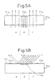
- Fig. 5A shows a resinous code plate 101a possessing a light transparency as a whole.
- Fig. 5B shows a resinous code plate 101b possessing a light opacity as a whole.
- the resinous code plate 101a shown in Fig. 5A, is provided, on the surface thereof (referred to as a plate face, in the present application), with a molded code-pattern surface including a flat surface area 111a and an irregular surface area 112a, the latter including a V-grooves array, and serves to encode light by using the reflection of the light on the irregular surface area 112a.
- a transmitted light when a transmitted light is used as a coded light output, a light "L" being incident from a light emitting section (not shown) in a direction normal to the plate face is transmitted through a plate portion having the flat surface area 111a, while is reflected in the irregular surface area 112a, as illustrated, so that a light receiving section (not shown) senses the flat surface area 111a as a bright area and the irregular surface area 112a as a dark area.
- the light receiving section when a reflected light is used as a coded light output, the light receiving section senses the flat surface area 111a as a dark area and the irregular surface area 112a as a bright area. Therefore, the flat surface area 111a and the irregular surface area 112a constitute the molded code-pattern surface including contrasted patterns ⁇ , ⁇ , ⁇ .
- the resinous code plate 101b shown in Fig. 5B, is provided, on the plate face thereof, with a molded code-pattern surface including a flat surface area 111b and an irregular surface area 112b, the latter including a V-groove array, the molded code-pattern surface being coated with a reflecting film 114, and serves to code a light by using the various reflecting directions of the light reflected on the flat and irregular surface areas 111b, 112b.
- the flat surface area 111b and the irregular surface area 112b constitute the molded code-pattern surface including contrasted patterns ⁇ , ⁇ , ⁇ .
- Fig. 6 shows a part of the molded code-pattern surface of a disk-shaped resinous code plate 101, as an example comparable with the present invention.
- a plurality of tracks 102, 103 having resolutions different from each other, are formed on the plate face in a concentric arrangement.
- the track 102 having lower resolution is provided with a molded code-pattern surface including a flat surface area 113 and an irregular surface area 112, which are disposed alternately along a circumferential direction at a predetermined pattern-pitch.
- the track 103 having higher resolution is provided with a molded code-pattern surface including a flat surface area 111 and an irregular surface area 112, which are disposed alternately along a circumferential direction at a predetermined pattern-pitch shorter than the pattern-pitch in the track 102.
- the resolution of the track depends on the pattern-pitch on the molded code-pattern surface.
- the irregular surface area 112 is constructed from a plurality of v-grooves extending in a radial direction.
- the molded code-pattern surface of the resinous code plate 102 is formed by processing patterned areas, corresponding to the irregular surface area 112 and the flat surface area 111, 113, on the molding surface of a mold used for molding the resinous code plate 101 from a molten resinous material, and transferring the shape of the molding surface to the resinous material.
- the irregular surface areas 112 of the tracks 102, 103 include a v-groove array continuously extending over both areas.
- the molten resinous material flows in the mold, during a molding process, in a direction corresponding to the longitudinal direction of the respective V-grooves in the irregular surface area 112, from the center toward the outer circumference of the resinous code plate 101 (i.e., in a radial direction of the resinous code plate 101), as shown by an arrow "P" in Fig. 6.
- a mold 120 is provided, on the molding surface 120a thereof, with a patterned area including a flat-surface shaping section 121 for forming the flat surface area 111, a V-groove array shaping section 122 for forming the irregular surface area 112, and a flat-surface shaping section 123 for forming the flat surface area 113 (Fig. 9A).
- a patterned area including a flat-surface shaping section 121 for forming the flat surface area 111, a V-groove array shaping section 122 for forming the irregular surface area 112, and a flat-surface shaping section 123 for forming the flat surface area 113 (Fig. 9A).
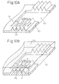
- a molten resinous material is poured into a cavity between the molds 120, 124 using, e.g., an injection-molding machine, the molten resinous material flows in the V-groove array shaping section 122 in a direction "P" corresponding to the longitudinal direction of the respective V-grooves, so as to form the irregular surface area 112, and then the molten resinous material flows into the flat-surface shaping section 123 located downstream, as seen in a resin flowing direction, of the V-groove array shaping section 122 for the track 103, so as to form the flat surface area 113 (Figs. 9E, 9F, 10A, 10B).
- the volume of the flat-surface shaping section 123 is larger than the volume of each V-groove shaping recess in the V-groove array shaping section 122, so that, at the instant when the molten resinous material flows from the V-groove array shaping section 122 into the flat-surface shaping section 123, the filling pressure of the molten resinous material is lowered.
- Such a change in the light shielding function in the irregular surface area 112 causes a change in a degree of contrast in relation to the flat surface area 111. Consequently, if the shape of the molding surface to the resinous material is unevenly transferred in the molding process of the resinous code plate, the accuracy of interpolation in the detecting process of an optical encoder may be influenced, and it is thus possible that the detection accuracy of the optical encoder is affected by, e.g., the fact that the error in interpolation locally increases at a certain position (or angle) of the resinous code plate.
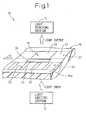
- FIG. 1 the basic constitution of an optical encoder 10, according to the present invention, will be described.
- the optical encoder 10 includes a light emitting section 12, a light receiving section 14, and a resinous code plate 16 disposed movably relative to the light emitting section 12 and the light receiving section 14 (in a direction shown by an arrow "M").
- the resinous or plastic code plate 16 includes a plurality of tracks 22, 24 respectively provided with molded code-pattern surfaces 18, 20 different from each other, for respectively converting a light input emitted from the light emitting section 12 into various coded-light outputs to be output toward the light receiving section 14, the tracks 22, 24 being formed on a plate face 16a in a side-by-side arrangement having a mutually identical extending direction.
- the resinous code plate 16 also includes a local structured-surface area 26 formed on the plate face 16a between the tracks 22, 24 arranged side-by-side relative to each other.
- the local structured-surface area 26 possesses a surface configuration different from the surface configuration of the molded code-pattern surfaces 18, 20 of the tracks 22, 24.
- structured-surface in the present application means various irregular or texturized surfaces including irregularities such as grooves, ribs, and so on.
- the filling conditions such as a filling pressure
- the filling conditions are uniform within the respective molded code-pattern surfaces 18, 20, so that it is possible to effectively reduce an unevenness in shape-transferring properties for the molding surface of the mold, which otherwise be caused due to a fluctuation in the filling pressure.
- the molding accuracy of the molded code-pattern surfaces 18, 20 of the respective tracks 22, 24 in the resinous code plate 16 is improved, the degree of contrast in the molded code-pattern surfaces 18, 20 is uniform and, thus, the influence on the accuracy of interpolation in the detecting process of the optical encoder 10 is eliminated, so that it is possible to stably ensure the required detection accuracy of the optical encoder 10.
- each of the molded code-pattern surfaces 18, 20 of the tracks 22, 24 includes a flat surface area 28, 30 and an irregular surface area 32, 34, adjacent to each other as seen in the extending direction of each track 22, 24.
- the molded code-pattern surface 18 of the track 22 is constituted in such a manner as to dispose, alternately, the flat surface area 28 and the irregular surface area 32 along the extending direction of the track 22 at a predetermined pattern-pitch, while the molded code-pattern surface 20 of the track 24 is constituted in such a manner as to dispose, alternately, the flat surface area 30 and the irregular surface area 34 along the extending direction of the track 24 at a predetermined pattern-pitch shorter than the pattern pitch in the track 22.
- Figs. 2A and 2B show a part of a molded code-pattern surface in a disk-shaped resinous code plate 40, according to one embodiment of the present invention.
- the resinous or plastic code plate 40 has a constitution as to be incorporated in a rotary encoder, and includes a plurality of tracks 42, 44 having resolutions different from each other and formed on the plate face 40a thereof in a concentric arrangement so as to respectively extend annularly about a rotary axis (not shown).
- the first track 42 having lower resolution is provided with a first molded code-pattern surface 50 for converting a light input into a first coded-light output, the first molded code-pattern surface 50 including a flat surface area 46 and an irregular surface area 48, which are disposed alternately along a circumferential direction at a predetermined pattern-pitch.
- the second track 44 having higher resolution is provided with a second molded code-pattern surface 56 for converting a light input into a second coded-light output different from the first coded-light output, the second molded code-pattern surface 56 including a flat surface area 52 and an irregular surface area 54, which are disposed alternately along a circumferential direction at a predetermined pattern-pitch shorter than the pattern-pitch in the first track 42.
- the resinous code plate 40 also includes a local structured-surface area 58 formed on the plate face 40a between the first and second tracks 42, 44.
- the local structured-surface area 58 possesses a surface configuration different from the surface configuration of the first and second molded code-pattern surfaces 50, 56.
- the resinous code plate 40 having the above-described molded code-pattern surface configuration is formed as a molded article solidified into a certain shape by pouring a molten resinous material into a mold.
- the first and second tracks 42, 44 are formed to be arranged side-by-side relative to each other as seen in a flowing direction "P" of the molten resinous material, in the mold, for forming the first and second molded code-pattern surfaces 50, 56.
- the flowing direction "P" of the molten resinous material in the mold is determined on the basis of the extending direction of the first linear structures 60 constituting the irregular surface areas 48, 54 of the first and second molded code-pattern surfaces 50, 56, which is, in the illustrated embodiment, a radial direction from the center toward the outer circumference of the resinous code plate 40.
- the second linear structure 62 constituting the local structured-surface area 58 extends in a circumferential direction perpendicular to the flowing direction "P" of the molten resinous material, between the first track 42 located downstream in a resin flowing direction and the second track 44 located upstream in the resin flowing direction.
- the local structured-surface area 58 may be formed, between the first and second tracks 42, 44, annularly along the entire circumference of the resinous code plate 40 or only within a desired angle range in the circumferential direction. However, it is advantageous that local structured-surface area 58 is formed so as to extend at least along a periphery of the flat surface area 46 of the first molded code-pattern surface 50 located downstream in the resin flowing direction. According to this arrangement, between the first and second molded code-pattern surfaces 50, 56 arranged side-by-side in the radial direction, the relatively narrower irregular surface area 54 located upstream in the resin flowing direction is substantially separated from the relatively wider flat surface area 46 located downstream in the resin flowing direction, by the local structured surface area 58, from the viewpoint of a resin flow.
- the extending direction of the second linear structure 62 of the local structured-surface area 58 is not limited to the direction perpendicular to the resin flowing direction "P", but may be any direction at a certain angle, other than a right angle, with the resin flowing direction "P", provided that the local structured-surface area 58 has no influence on the light coding functions of the first and second tracks 42, 44 located at both sides of the local structured-surface area 58.
- the second linear structure 62 of the local structured-surface area 58 is formed as a light interrupting portion extending annularly between the first and second tracks 42, 44 for a light incident to the tracks 42, 44, the influence on the light coding functions of the first and second tracks 42, 44 is eliminated.
- the local structured-surface area 58 may include a groove recessed in the plate face 40a.
- the groove may be composed of a v-groove (Fig. 2B), a trapezoidal groove, a rounded groove, and so on.
- the groove is not restricted to the linear structure, but may be a dispersedly arrangeable groove such as a dimple.
- the local structured-surface area 58 may include a projection protruding from the plate face 40a.
- the projection may be composed of a V-ridge, a trapezoidal ridge, a rounded ridge, and so on.
- the projection is not restricted to the linear structure, but may be a dispersedly arrangeable projection such as a bump.
- the local structured-surface area 58 has a surface configuration and/or a location capable of causing an intentional local change of pressure in the flow of molten resinous material in the mold
- the filling conditions, such as a filling pressure, of the molten resinous material for forming the molded code-pattern surfaces 50, 56 of the first and second tracks 42, 44 arranged adjacent to the local structured-surface area 58, which appears to influence the flowing mode of the resinous material in the mold are uniform within the respective molded code-pattern surfaces 50, 56, so that it is possible to effectively reduce an unevenness in shape-transferring properties for the molding surface of the mold, which otherwise be caused due to the fluctuation of the filling pressure.
- the molding accuracy of the molded code-pattern surfaces 50, 56 of the first and second tracks 42, 44 in the resinous code plate 40 is improved, so that it is possible to stably ensure the required detection accuracy of the optical encoder.
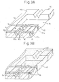
- Figs. 3A and 3B schematically show the main portion of a mold 70 for molding the resinous code plate 40 described above.
- the mold 70 is provided, in the molding surface 70a thereof, with a first patterned area 72 for forming the first track 42 of the resinous code plate 40; a second patterned area 74 for forming the second track 44 of the resinous code plate 40, the second patterned area 74 being arranged upstream of the first patterned area 72 as seen in the flowing direction "P" of a molten resinous material; and a third patterned area 76 for forming the local structured-surface area 58 of the resinous code pate 40, the third patterned area 76 being arranged between the first patterned area 72 and the second patterned area 74 as seen in the flowing direction "P" of the molten resinous material.
- the third patterned area 76 for forming the local structured-surface area 58 is also provided at a side upstream of the second patterned area 74 as seen in the flowing direction "P" of the molten
- the first patterned area 72 includes a flat-surface shaping section 78 for forming the flat surface area 46 of the first track 42;
- the second patterned area 74 includes a V-groove array shaping section 80 for forming the irregular surface area 54 of the second track 44; and
- each of the third patterned area 76 includes a transverse-groove shaping section 82 for forming the local structured-surface area 58.
- the V-groove array shaping section 80 is shown only by one root forming portion 80a for forming a root of the v-groove array and two ridge forming portions 80b for forming ridges of the V-groove array, in the irregular surface area 54 of the second track 44 of the resinous code plate 40.
- the V-groove array shaping section 80 is actually composed of plural root forming portions 80a and plural ridge forming portions 80b, arranged alternately with each other.
- the transverse-groove shaping section 82 is shown only by one ridge forming portion 82a for forming a ridge of the V-groove array in the local structured-surface area 58 of the resinous code plate 40, but is actually composed of plural root forming portions (not shown) and plural ridge forming portions 82a, arranged alternately with each other.
- the depth "h" of the ridge forming portion 82a of the transverse-groove shaping section 82 may be desirably determined, and may be deeper or shallower than the depth of the ridge forming portion 80b of the V-groove array shaping section 80.
- the V-groove array shaping section for forming the irregular surface area 48 of the first track 42 is not illustrated as a matter of convenience.
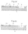
- the molten resinous material flows in the V-groove array shaping section 80 in a direction "P" corresponding to the longitudinal direction of the respective v-grooves, so as to form the irregular surface area 54, and then the molten resinous material flows into the flat-surface shaping section 78 located downstream of the V-groove array shaping section 80, as seen in the resin flowing direction, so as to form the flat surface area 46.
- the filling pressure is fully applied to the ridge forming portion 82a of the V-groove array shaping section 80 so as to fill the resinous material therein.
- the V-groove array shaping section 80 is arranged between two transverse-groove shaping sections 82 at the upstream and downstream sides, as seen in the resin flowing direction "P", so that the filling pressure in the V-groove array shaping section 80 is substantially determined solely by the configuration of the transverse-groove shaping sections 82.
- the transverse-groove shaping sections 82 are provided at both sides of the V-groove array shaping section 80 in the resin flowing direction, so that, even when the relatively wider flat-surface shaping section 78, which may act as a resin reservoir, is arranged at the downstream side, the molten resinous material flowing along the v-groove array shaping section 80 is not affected by the flat-surface shaping section 78, and thus can maintain the pressure thereof at a generally even level between two transverse-groove shaping sections 82, which results in the uniform filling pressure.
- the irregular surface area 54 is molded with a high accuracy, similar to a case where no flat-surface shaping section is arranged at a downstream side.
- the transverse-groove shaping sections 82 may have a slight influence, of a reduction in the filling pressure, on the molten resinous material flowing along the V-groove array shaping section 80, the shape-transferring properties for the molding surface 70a of the mold 70 is improved in its entirety because the influence of a significant reduction in pressure, due to the flat-surface shaping section 78, is substantially eliminated.
- the molten resinous material flowing along the V-groove array shaping section 122, in the mold 120 is affected by a reduction in pressure generated at the instant when the molten resinous material flows into the flat-surface shaping section 123 arranged at the downstream side in the resin flowing direction, which in turn causes a reduction in pressure in the V-groove array shaping section 122.
- an unevenness in shape-transferring properties for the molding surface 120a of the mold 120 is caused in the V-groove array shaping section 122, in accordance with the location of the flat-surface shaping section 123.
Landscapes
- Physics & Mathematics (AREA)
- General Physics & Mathematics (AREA)
- Engineering & Computer Science (AREA)
- Manufacturing & Machinery (AREA)
- Mechanical Engineering (AREA)
- Optical Transform (AREA)
- Moulds For Moulding Plastics Or The Like (AREA)
Abstract
Description
Claims (14)
- An optical encoder, comprising:wherein said resinous code plate includes a local structured-surface area formed on said plate face between said tracks arranged side-by-side relative to each other, said local structured-surface area possessing a surface configuration different from said molded code-pattern surfaces of said tracks.a light emitting section;a light receiving section; anda resinous code plate disposed movably relative to said light emitting section and said light receiving section, said resinous code plate including a plurality of tracks respectively provided with molded code-pattern surfaces different from each other, said tracks being formed on a plate face in a side-by-side arrangement exhibiting a mutually identical extending direction;
- An optical encoder, as set forth in claim 1, wherein a molded code-pattern surface of each of said plurality of tracks includes a flat surface area and an irregular surface area, adjacent to each other as seen in the extending direction of each track; and wherein said local structured-surface area is formed between said flat surface area of said molded code-pattern surface of one track and said irregular surface area of said molded code-pattern surface of another track arranged side-by-side relative to said one track.
- An optical encoder, as set forth in claim 2, wherein said irregular surface area of said molded code-pattern surface includes a first linear structure extending in a predetermined direction; and wherein said local structured-surface area includes a second linear structure extending in a direction intersecting said first linear structure of said irregular surface area.
- An optical encoder, as set forth in claim 1, wherein said resinous code plate comprises a molded article solidified into a certain shape by pouring a molten resinous material into a mold; and wherein said plurality of tracks are formed to be arranged side-by-side relative to each other as seen from a flowing direction of the molten resinous material, in the mold, for forming said molded code-pattern surfaces of said tracks.
- An optical encoder, as set forth in claim 4, wherein said local structured-surface area includes a linear structure extending in a direction intersecting said flowing direction of said molten resinous material between said tracks arranged side-by-side.
- A resinous code plate of an optical encoder, comprising:a first track provided with a first molded code-pattern surface for converting a light input into a first coded-light output, said first track being formed on a plate face;a second track provided with a second molded code-pattern surface for converting a light input into a second coded-light output different from said first coded-light output, said second track being formed on said plate face in a side-by-side arrangement exhibiting an extending direction identical to an extending direction of said first track; anda local structured-surface area formed on said plate face between said first track and said second track, said local structured-surface area possessing a surface configuration different from said first molded code-pattern surface and said second molded code-pattern surface.
- A resinous code plate, as set forth in claim 6, wherein each of said first molded code-pattern surface and said second molded code-pattern surface includes a flat surface area and an irregular surface area, adjacent to each other as seen in the extending direction of each of said first track and said second track; and wherein said local structured-surface area is formed between said flat surface area of said first molded code-pattern surface and said irregular surface area of said second molded code-pattern surface.
- A resinous code plate, as set forth in claim 7, wherein said irregular surface area of each of said first molded code-pattern surface and said second molded code-pattern surface includes a first linear structure extending in a predetermined direction; and wherein said local structured-surface area includes a second linear structure extending in a direction intersecting said first linear structure of said irregular surface area.
- A resinous code plate, as set forth in claim 8, wherein said second linear structure extends along a periphery of said flat surface area of said first molded code-pattern surface.
- A resinous code plate, as set forth in claim 6, comprising a molded article solidified into a certain shape by pouring a molten resinous material into a mold; wherein said first track and said second track are formed to be arranged side-by-side relative to each other as seen in a flowing direction of the molten resinous material, in the mold, for forming said first molded code-pattern surface and said second molded code-pattern surface.
- An optical encoder, as set forth in claim 10, wherein said local structured-surface area includes a linear structure extending in a direction intersecting said flowing direction of said molten resinous material between said first track and said second track.
- An optical encoder, as set forth in claim 6, wherein said local structured-surface area includes a groove recessed in said plate face.
- An optical encoder, as set forth in claim 6, wherein said local structured-surface area includes a projection protruding from said plate face.
- A mold for molding a resinous code plate, as set forth in claim 6, from a molten resinous material, comprising:a first patterned area for forming said first track;a second patterned area for forming said second track, said second patterned area being arranged upstream of said first patterned area as seen in a flowing direction of a molten resinous material; anda third patterned area for forming said local structured-surface area, said third patterned area being arranged between said first patterned area and said second patterned area as seen from the flowing direction of the molten resinous material.
Applications Claiming Priority (2)
| Application Number | Priority Date | Filing Date | Title |
|---|---|---|---|
| JP2003102970 | 2003-04-07 | ||
| JP2003102970A JP3851616B2 (en) | 2003-04-07 | 2003-04-07 | Code board manufacturing method for optical encoder |
Publications (3)
| Publication Number | Publication Date |
|---|---|
| EP1467186A2 true EP1467186A2 (en) | 2004-10-13 |
| EP1467186A3 EP1467186A3 (en) | 2007-04-18 |
| EP1467186B1 EP1467186B1 (en) | 2012-11-14 |
Family
ID=32866705
Family Applications (1)
| Application Number | Title | Priority Date | Filing Date |
|---|---|---|---|
| EP04008376A Expired - Lifetime EP1467186B1 (en) | 2003-04-07 | 2004-04-06 | Optical encoder with resinous code plate |
Country Status (4)
| Country | Link |
|---|---|
| US (1) | US7374090B2 (en) |
| EP (1) | EP1467186B1 (en) |
| JP (1) | JP3851616B2 (en) |
| CN (1) | CN100561135C (en) |
Families Citing this family (9)
| Publication number | Priority date | Publication date | Assignee | Title |
|---|---|---|---|---|
| WO2012042568A1 (en) * | 2010-09-29 | 2012-04-05 | 三菱電機株式会社 | Method of producing resin component, and optical encoder comprising the resin component |
| US8387882B2 (en) * | 2011-07-07 | 2013-03-05 | Metrologic Instruments, Inc. | Decodable indicia reading terminal with a platter to inhibit light reflection |
| US20140295032A1 (en) * | 2011-11-15 | 2014-10-02 | Nestec S.A. | Optical readable code support and capsule for preparing a beverage having such code support providing an enhanced readable optical signal |
| JP6291156B2 (en) * | 2012-04-23 | 2018-03-14 | マクセル株式会社 | Resin encoder scale, encoder, resin encoder scale manufacturing method, and encoder manufacturing method |
| CN104180827A (en) * | 2013-05-23 | 2014-12-03 | 株式会社精工技研 | Code plate of optical encoder |
| JP6057884B2 (en) * | 2013-12-16 | 2017-01-11 | 三菱電機株式会社 | Encoder and manufacturing method thereof |
| JP2015215168A (en) * | 2014-05-07 | 2015-12-03 | ファナック株式会社 | Reflective optical encoder with resin code plate |
| CN104070785B (en) * | 2014-06-30 | 2016-03-16 | 长春工业大学 | Transfer belt code-bar image speed limit acquisition system |
| JP6932983B2 (en) * | 2017-05-01 | 2021-09-08 | セイコーエプソン株式会社 | Encoder Scales, Encoder Scale Manufacturing Methods, Encoders, Robots and Printers |
Citations (2)
| Publication number | Priority date | Publication date | Assignee | Title |
|---|---|---|---|---|
| EP0947807A2 (en) | 1998-04-01 | 1999-10-06 | Fanuc Ltd. | Optical encoder |
| US20020067688A1 (en) | 1997-09-02 | 2002-06-06 | Tetsuya Iida | Optical disc and mold for manufacturing the optical disc |
Family Cites Families (6)
| Publication number | Priority date | Publication date | Assignee | Title |
|---|---|---|---|---|
| US4820918A (en) * | 1985-06-28 | 1989-04-11 | Canon Kabushiki Kaisha | Optical encoder including transparent substrates having formed indicators therein |
| JPH0752107B2 (en) | 1985-06-28 | 1995-06-05 | キヤノン株式会社 | Optical scale |
| JPS62265523A (en) | 1986-05-13 | 1987-11-18 | Omron Tateisi Electronics Co | Optical rotary encoder |
| JP3466718B2 (en) | 1994-07-08 | 2003-11-17 | キヤノン株式会社 | Optical scale molding die and method of manufacturing optical scale |
| JP3574733B2 (en) | 1997-11-21 | 2004-10-06 | アスモ株式会社 | Rotation angle detector |
| US6814897B2 (en) * | 1998-03-27 | 2004-11-09 | Discovision Associates | Method for manufacturing a molding tool used for substrate molding |
-
2003
- 2003-04-07 JP JP2003102970A patent/JP3851616B2/en not_active Expired - Fee Related
-
2004
- 2004-04-06 EP EP04008376A patent/EP1467186B1/en not_active Expired - Lifetime
- 2004-04-07 CN CNB2004100430966A patent/CN100561135C/en not_active Expired - Lifetime
- 2004-04-07 US US10/819,149 patent/US7374090B2/en not_active Expired - Lifetime
Patent Citations (2)
| Publication number | Priority date | Publication date | Assignee | Title |
|---|---|---|---|---|
| US20020067688A1 (en) | 1997-09-02 | 2002-06-06 | Tetsuya Iida | Optical disc and mold for manufacturing the optical disc |
| EP0947807A2 (en) | 1998-04-01 | 1999-10-06 | Fanuc Ltd. | Optical encoder |
Also Published As
| Publication number | Publication date |
|---|---|
| EP1467186A3 (en) | 2007-04-18 |
| CN1538148A (en) | 2004-10-20 |
| US20040195331A1 (en) | 2004-10-07 |
| US7374090B2 (en) | 2008-05-20 |
| EP1467186B1 (en) | 2012-11-14 |
| CN100561135C (en) | 2009-11-18 |
| JP3851616B2 (en) | 2006-11-29 |
| JP2004309302A (en) | 2004-11-04 |
Similar Documents
| Publication | Publication Date | Title |
|---|---|---|
| CN104246447B (en) | Resin-made encoder, resin-made encoder metal die, the manufacture method and encoder of resin-made encoder | |
| EP1467186B1 (en) | Optical encoder with resinous code plate | |
| US6232593B1 (en) | Optical encoder | |
| US7612331B2 (en) | Code disk with a plurality of tracks having different patterns | |
| US4300470A (en) | Luminant pointer for meters | |
| KR100867053B1 (en) | Optical encoder | |
| CN100573053C (en) | Utilize the optical encoding of total internal reflection | |
| US20010024327A1 (en) | Lens array and lens array assembly | |
| US4820918A (en) | Optical encoder including transparent substrates having formed indicators therein | |
| JP3730232B2 (en) | Optical encoder | |
| CN101144528A (en) | Resin end face gear and metal mold for injection-molding of the same | |
| KR100845536B1 (en) | Working method of die for use for fresnel lens, die worked through execution of the working method, and fresnel lens worked from the die | |
| JPH1034762A (en) | High precision gear and its injection molding method | |
| KR20040010022A (en) | Optical transmitter element and positioning device | |
| CN104180827A (en) | Code plate of optical encoder | |
| JP4332514B2 (en) | Encoder code plate, encoder, mold manufacturing method for encoder code plate, mold for encoder code plate, and manufacturing method of encoder code plate | |
| JP2020085771A (en) | Marker | |
| CN104412070B (en) | The method and system of coding is recorded, implementing track and the track preparation method for encoding | |
| JPH0627654B2 (en) | A device that optically detects the position and speed of a moving object | |
| JPS62128615A (en) | optical encoder | |
| WO2019074036A1 (en) | Marker | |
| JP4292567B2 (en) | Optical encoder | |
| JPH09177944A (en) | Injection-molded gear | |
| JP2013134203A (en) | Optical encoder and method of manufacturing the same | |
| CN116888435A (en) | Optical encoder |
Legal Events
| Date | Code | Title | Description |
|---|---|---|---|
| PUAI | Public reference made under article 153(3) epc to a published international application that has entered the european phase |
Free format text: ORIGINAL CODE: 0009012 |
|
| 17P | Request for examination filed |
Effective date: 20040406 |
|
| AK | Designated contracting states |
Kind code of ref document: A2 Designated state(s): AT BE BG CH CY CZ DE DK EE ES FI FR GB GR HU IE IT LI LU MC NL PL PT RO SE SI SK TR |
|
| AX | Request for extension of the european patent |
Extension state: AL HR LT LV MK |
|
| RIN1 | Information on inventor provided before grant (corrected) |
Inventor name: TERASHIMA, HIROYA,ROOM 11-102 Inventor name: IMAI, KEISUKE,ROOM 10-206 |
|
| PUAL | Search report despatched |
Free format text: ORIGINAL CODE: 0009013 |
|
| AK | Designated contracting states |
Kind code of ref document: A3 Designated state(s): AT BE BG CH CY CZ DE DK EE ES FI FR GB GR HU IE IT LI LU MC NL PL PT RO SE SI SK TR |
|
| AX | Request for extension of the european patent |
Extension state: AL HR LT LV MK |
|
| RIC1 | Information provided on ipc code assigned before grant |
Ipc: G01D 5/347 20060101AFI20040728BHEP Ipc: B29C 45/00 20060101ALI20070309BHEP |
|
| AKX | Designation fees paid |
Designated state(s): DE |
|
| 17Q | First examination report despatched |
Effective date: 20100325 |
|
| RAP1 | Party data changed (applicant data changed or rights of an application transferred) |
Owner name: FANUC CORPORATION |
|
| GRAP | Despatch of communication of intention to grant a patent |
Free format text: ORIGINAL CODE: EPIDOSNIGR1 |
|
| RIN1 | Information on inventor provided before grant (corrected) |
Inventor name: TERASHIMA, HIROYA Inventor name: IMAI, KEISUKE |
|
| GRAS | Grant fee paid |
Free format text: ORIGINAL CODE: EPIDOSNIGR3 |
|
| RIN1 | Information on inventor provided before grant (corrected) |
Inventor name: IMAI, KEISUKE Inventor name: TERASHIMA, HIROYA |
|
| GRAA | (expected) grant |
Free format text: ORIGINAL CODE: 0009210 |
|
| RIN1 | Information on inventor provided before grant (corrected) |
Inventor name: IMAI, KEISUKE Inventor name: TERASHIMA, HIROYA |
|
| AK | Designated contracting states |
Kind code of ref document: B1 Designated state(s): DE |
|
| REG | Reference to a national code |
Ref country code: DE Ref legal event code: R096 Ref document number: 602004040002 Country of ref document: DE Effective date: 20130110 |
|
| PLBE | No opposition filed within time limit |
Free format text: ORIGINAL CODE: 0009261 |
|
| STAA | Information on the status of an ep patent application or granted ep patent |
Free format text: STATUS: NO OPPOSITION FILED WITHIN TIME LIMIT |
|
| 26N | No opposition filed |
Effective date: 20130815 |
|
| REG | Reference to a national code |
Ref country code: DE Ref legal event code: R097 Ref document number: 602004040002 Country of ref document: DE Effective date: 20130815 |
|
| PGFP | Annual fee paid to national office [announced via postgrant information from national office to epo] |
Ref country code: DE Payment date: 20230228 Year of fee payment: 20 |
|
| REG | Reference to a national code |
Ref country code: DE Ref legal event code: R071 Ref document number: 602004040002 Country of ref document: DE |