EP1467168A2 - Heat exchanger and evaporator - Google Patents
Heat exchanger and evaporator Download PDFInfo
- Publication number
- EP1467168A2 EP1467168A2 EP04008379A EP04008379A EP1467168A2 EP 1467168 A2 EP1467168 A2 EP 1467168A2 EP 04008379 A EP04008379 A EP 04008379A EP 04008379 A EP04008379 A EP 04008379A EP 1467168 A2 EP1467168 A2 EP 1467168A2
- Authority
- EP
- European Patent Office
- Prior art keywords
- cylinder
- external
- fluid passage
- external cylinder
- heat exchanger
- Prior art date
- Legal status (The legal status is an assumption and is not a legal conclusion. Google has not performed a legal analysis and makes no representation as to the accuracy of the status listed.)
- Granted
Links
Images


Classifications
-
- F—MECHANICAL ENGINEERING; LIGHTING; HEATING; WEAPONS; BLASTING
- F28—HEAT EXCHANGE IN GENERAL
- F28D—HEAT-EXCHANGE APPARATUS, NOT PROVIDED FOR IN ANOTHER SUBCLASS, IN WHICH THE HEAT-EXCHANGE MEDIA DO NOT COME INTO DIRECT CONTACT
- F28D9/00—Heat-exchange apparatus having stationary plate-like or laminated conduit assemblies for both heat-exchange media, the media being in contact with different sides of a conduit wall
- F28D9/0025—Heat-exchange apparatus having stationary plate-like or laminated conduit assemblies for both heat-exchange media, the media being in contact with different sides of a conduit wall the conduits being formed by zig-zag bend plates
-
- B—PERFORMING OPERATIONS; TRANSPORTING
- B01—PHYSICAL OR CHEMICAL PROCESSES OR APPARATUS IN GENERAL
- B01B—BOILING; BOILING APPARATUS ; EVAPORATION; EVAPORATION APPARATUS
- B01B1/00—Boiling; Boiling apparatus for physical or chemical purposes ; Evaporation in general
- B01B1/005—Evaporation for physical or chemical purposes; Evaporation apparatus therefor, e.g. evaporation of liquids for gas phase reactions
-
- B—PERFORMING OPERATIONS; TRANSPORTING
- B01—PHYSICAL OR CHEMICAL PROCESSES OR APPARATUS IN GENERAL
- B01J—CHEMICAL OR PHYSICAL PROCESSES, e.g. CATALYSIS OR COLLOID CHEMISTRY; THEIR RELEVANT APPARATUS
- B01J19/00—Chemical, physical or physico-chemical processes in general; Their relevant apparatus
- B01J19/24—Stationary reactors without moving elements inside
- B01J19/248—Reactors comprising multiple separated flow channels
- B01J19/2485—Monolithic reactors
-
- B—PERFORMING OPERATIONS; TRANSPORTING
- B01—PHYSICAL OR CHEMICAL PROCESSES OR APPARATUS IN GENERAL
- B01J—CHEMICAL OR PHYSICAL PROCESSES, e.g. CATALYSIS OR COLLOID CHEMISTRY; THEIR RELEVANT APPARATUS
- B01J19/00—Chemical, physical or physico-chemical processes in general; Their relevant apparatus
- B01J19/24—Stationary reactors without moving elements inside
- B01J19/248—Reactors comprising multiple separated flow channels
- B01J19/249—Plate-type reactors
-
- C—CHEMISTRY; METALLURGY
- C01—INORGANIC CHEMISTRY
- C01B—NON-METALLIC ELEMENTS; COMPOUNDS THEREOF; METALLOIDS OR COMPOUNDS THEREOF NOT COVERED BY SUBCLASS C01C
- C01B3/00—Hydrogen; Gaseous mixtures containing hydrogen; Separation of hydrogen from mixtures containing it; Purification of hydrogen; Reversible storage of hydrogen
- C01B3/02—Production of hydrogen; Production of gaseous mixtures containing hydrogen
- C01B3/32—Production of hydrogen; Production of gaseous mixtures containing hydrogen by reaction of gaseous or liquid organic compounds with gasifying agents, e.g. water, carbon dioxide or air
- C01B3/34—Production of hydrogen; Production of gaseous mixtures containing hydrogen by reaction of gaseous or liquid organic compounds with gasifying agents, e.g. water, carbon dioxide or air by reaction of hydrocarbons with gasifying agents
- C01B3/48—Production of hydrogen; Production of gaseous mixtures containing hydrogen by reaction of gaseous or liquid organic compounds with gasifying agents, e.g. water, carbon dioxide or air by reaction of hydrocarbons with gasifying agents followed by reaction of water vapour with carbon monoxide
-
- F—MECHANICAL ENGINEERING; LIGHTING; HEATING; WEAPONS; BLASTING
- F28—HEAT EXCHANGE IN GENERAL
- F28D—HEAT-EXCHANGE APPARATUS, NOT PROVIDED FOR IN ANOTHER SUBCLASS, IN WHICH THE HEAT-EXCHANGE MEDIA DO NOT COME INTO DIRECT CONTACT
- F28D7/00—Heat-exchange apparatus having stationary tubular conduit assemblies for both heat-exchange media, the media being in contact with different sides of a conduit wall
- F28D7/10—Heat-exchange apparatus having stationary tubular conduit assemblies for both heat-exchange media, the media being in contact with different sides of a conduit wall the conduits being arranged one within the other, e.g. concentrically
- F28D7/12—Heat-exchange apparatus having stationary tubular conduit assemblies for both heat-exchange media, the media being in contact with different sides of a conduit wall the conduits being arranged one within the other, e.g. concentrically the surrounding tube being closed at one end, e.g. return type
-
- H—ELECTRICITY
- H01—ELECTRIC ELEMENTS
- H01M—PROCESSES OR MEANS, e.g. BATTERIES, FOR THE DIRECT CONVERSION OF CHEMICAL ENERGY INTO ELECTRICAL ENERGY
- H01M8/00—Fuel cells; Manufacture thereof
- H01M8/04—Auxiliary arrangements, e.g. for control of pressure or for circulation of fluids
- H01M8/04007—Auxiliary arrangements, e.g. for control of pressure or for circulation of fluids related to heat exchange
- H01M8/04014—Heat exchange using gaseous fluids; Heat exchange by combustion of reactants
- H01M8/04022—Heating by combustion
-
- H—ELECTRICITY
- H01—ELECTRIC ELEMENTS
- H01M—PROCESSES OR MEANS, e.g. BATTERIES, FOR THE DIRECT CONVERSION OF CHEMICAL ENERGY INTO ELECTRICAL ENERGY
- H01M8/00—Fuel cells; Manufacture thereof
- H01M8/04—Auxiliary arrangements, e.g. for control of pressure or for circulation of fluids
- H01M8/04007—Auxiliary arrangements, e.g. for control of pressure or for circulation of fluids related to heat exchange
- H01M8/04067—Heat exchange or temperature measuring elements, thermal insulation, e.g. heat pipes, heat pumps, fins
- H01M8/04074—Heat exchange unit structures specially adapted for fuel cell
-
- B—PERFORMING OPERATIONS; TRANSPORTING
- B01—PHYSICAL OR CHEMICAL PROCESSES OR APPARATUS IN GENERAL
- B01J—CHEMICAL OR PHYSICAL PROCESSES, e.g. CATALYSIS OR COLLOID CHEMISTRY; THEIR RELEVANT APPARATUS
- B01J2219/00—Chemical, physical or physico-chemical processes in general; Their relevant apparatus
- B01J2219/24—Stationary reactors without moving elements inside
- B01J2219/2401—Reactors comprising multiple separate flow channels
- B01J2219/245—Plate-type reactors
- B01J2219/2451—Geometry of the reactor
- B01J2219/2453—Plates arranged in parallel
-
- B—PERFORMING OPERATIONS; TRANSPORTING
- B01—PHYSICAL OR CHEMICAL PROCESSES OR APPARATUS IN GENERAL
- B01J—CHEMICAL OR PHYSICAL PROCESSES, e.g. CATALYSIS OR COLLOID CHEMISTRY; THEIR RELEVANT APPARATUS
- B01J2219/00—Chemical, physical or physico-chemical processes in general; Their relevant apparatus
- B01J2219/24—Stationary reactors without moving elements inside
- B01J2219/2401—Reactors comprising multiple separate flow channels
- B01J2219/245—Plate-type reactors
- B01J2219/2451—Geometry of the reactor
- B01J2219/2456—Geometry of the plates
- B01J2219/2459—Corrugated plates
-
- B—PERFORMING OPERATIONS; TRANSPORTING
- B01—PHYSICAL OR CHEMICAL PROCESSES OR APPARATUS IN GENERAL
- B01J—CHEMICAL OR PHYSICAL PROCESSES, e.g. CATALYSIS OR COLLOID CHEMISTRY; THEIR RELEVANT APPARATUS
- B01J2219/00—Chemical, physical or physico-chemical processes in general; Their relevant apparatus
- B01J2219/24—Stationary reactors without moving elements inside
- B01J2219/2401—Reactors comprising multiple separate flow channels
- B01J2219/245—Plate-type reactors
- B01J2219/2451—Geometry of the reactor
- B01J2219/2456—Geometry of the plates
- B01J2219/246—Perforated plates
-
- B—PERFORMING OPERATIONS; TRANSPORTING
- B01—PHYSICAL OR CHEMICAL PROCESSES OR APPARATUS IN GENERAL
- B01J—CHEMICAL OR PHYSICAL PROCESSES, e.g. CATALYSIS OR COLLOID CHEMISTRY; THEIR RELEVANT APPARATUS
- B01J2219/00—Chemical, physical or physico-chemical processes in general; Their relevant apparatus
- B01J2219/24—Stationary reactors without moving elements inside
- B01J2219/2401—Reactors comprising multiple separate flow channels
- B01J2219/245—Plate-type reactors
- B01J2219/2461—Heat exchange aspects
- B01J2219/2465—Two reactions in indirect heat exchange with each other
-
- B—PERFORMING OPERATIONS; TRANSPORTING
- B01—PHYSICAL OR CHEMICAL PROCESSES OR APPARATUS IN GENERAL
- B01J—CHEMICAL OR PHYSICAL PROCESSES, e.g. CATALYSIS OR COLLOID CHEMISTRY; THEIR RELEVANT APPARATUS
- B01J2219/00—Chemical, physical or physico-chemical processes in general; Their relevant apparatus
- B01J2219/24—Stationary reactors without moving elements inside
- B01J2219/2401—Reactors comprising multiple separate flow channels
- B01J2219/245—Plate-type reactors
- B01J2219/2469—Feeding means
- B01J2219/247—Feeding means for the reactants
-
- B—PERFORMING OPERATIONS; TRANSPORTING
- B01—PHYSICAL OR CHEMICAL PROCESSES OR APPARATUS IN GENERAL
- B01J—CHEMICAL OR PHYSICAL PROCESSES, e.g. CATALYSIS OR COLLOID CHEMISTRY; THEIR RELEVANT APPARATUS
- B01J2219/00—Chemical, physical or physico-chemical processes in general; Their relevant apparatus
- B01J2219/24—Stationary reactors without moving elements inside
- B01J2219/2401—Reactors comprising multiple separate flow channels
- B01J2219/245—Plate-type reactors
- B01J2219/2476—Construction materials
- B01J2219/2477—Construction materials of the catalysts
- B01J2219/2482—Catalytically active foils; Plates having catalytically activity on their own
-
- C—CHEMISTRY; METALLURGY
- C01—INORGANIC CHEMISTRY
- C01B—NON-METALLIC ELEMENTS; COMPOUNDS THEREOF; METALLOIDS OR COMPOUNDS THEREOF NOT COVERED BY SUBCLASS C01C
- C01B2203/00—Integrated processes for the production of hydrogen or synthesis gas
-
- C—CHEMISTRY; METALLURGY
- C01—INORGANIC CHEMISTRY
- C01B—NON-METALLIC ELEMENTS; COMPOUNDS THEREOF; METALLOIDS OR COMPOUNDS THEREOF NOT COVERED BY SUBCLASS C01C
- C01B2203/00—Integrated processes for the production of hydrogen or synthesis gas
- C01B2203/02—Processes for making hydrogen or synthesis gas
- C01B2203/0205—Processes for making hydrogen or synthesis gas containing a reforming step
- C01B2203/0227—Processes for making hydrogen or synthesis gas containing a reforming step containing a catalytic reforming step
- C01B2203/0244—Processes for making hydrogen or synthesis gas containing a reforming step containing a catalytic reforming step the reforming step being an autothermal reforming step, e.g. secondary reforming processes
-
- C—CHEMISTRY; METALLURGY
- C01—INORGANIC CHEMISTRY
- C01B—NON-METALLIC ELEMENTS; COMPOUNDS THEREOF; METALLOIDS OR COMPOUNDS THEREOF NOT COVERED BY SUBCLASS C01C
- C01B2203/00—Integrated processes for the production of hydrogen or synthesis gas
- C01B2203/02—Processes for making hydrogen or synthesis gas
- C01B2203/0283—Processes for making hydrogen or synthesis gas containing a CO-shift step, i.e. a water gas shift step
-
- C—CHEMISTRY; METALLURGY
- C01—INORGANIC CHEMISTRY
- C01B—NON-METALLIC ELEMENTS; COMPOUNDS THEREOF; METALLOIDS OR COMPOUNDS THEREOF NOT COVERED BY SUBCLASS C01C
- C01B2203/00—Integrated processes for the production of hydrogen or synthesis gas
- C01B2203/04—Integrated processes for the production of hydrogen or synthesis gas containing a purification step for the hydrogen or the synthesis gas
- C01B2203/0435—Catalytic purification
- C01B2203/044—Selective oxidation of carbon monoxide
-
- C—CHEMISTRY; METALLURGY
- C01—INORGANIC CHEMISTRY
- C01B—NON-METALLIC ELEMENTS; COMPOUNDS THEREOF; METALLOIDS OR COMPOUNDS THEREOF NOT COVERED BY SUBCLASS C01C
- C01B2203/00—Integrated processes for the production of hydrogen or synthesis gas
- C01B2203/04—Integrated processes for the production of hydrogen or synthesis gas containing a purification step for the hydrogen or the synthesis gas
- C01B2203/0465—Composition of the impurity
- C01B2203/047—Composition of the impurity the impurity being carbon monoxide
-
- C—CHEMISTRY; METALLURGY
- C01—INORGANIC CHEMISTRY
- C01B—NON-METALLIC ELEMENTS; COMPOUNDS THEREOF; METALLOIDS OR COMPOUNDS THEREOF NOT COVERED BY SUBCLASS C01C
- C01B2203/00—Integrated processes for the production of hydrogen or synthesis gas
- C01B2203/06—Integration with other chemical processes
- C01B2203/066—Integration with other chemical processes with fuel cells
-
- C—CHEMISTRY; METALLURGY
- C01—INORGANIC CHEMISTRY
- C01B—NON-METALLIC ELEMENTS; COMPOUNDS THEREOF; METALLOIDS OR COMPOUNDS THEREOF NOT COVERED BY SUBCLASS C01C
- C01B2203/00—Integrated processes for the production of hydrogen or synthesis gas
- C01B2203/08—Methods of heating or cooling
- C01B2203/0805—Methods of heating the process for making hydrogen or synthesis gas
- C01B2203/0811—Methods of heating the process for making hydrogen or synthesis gas by combustion of fuel
-
- C—CHEMISTRY; METALLURGY
- C01—INORGANIC CHEMISTRY
- C01B—NON-METALLIC ELEMENTS; COMPOUNDS THEREOF; METALLOIDS OR COMPOUNDS THEREOF NOT COVERED BY SUBCLASS C01C
- C01B2203/00—Integrated processes for the production of hydrogen or synthesis gas
- C01B2203/08—Methods of heating or cooling
- C01B2203/0805—Methods of heating the process for making hydrogen or synthesis gas
- C01B2203/0833—Heating by indirect heat exchange with hot fluids, other than combustion gases, product gases or non-combustive exothermic reaction product gases
-
- C—CHEMISTRY; METALLURGY
- C01—INORGANIC CHEMISTRY
- C01B—NON-METALLIC ELEMENTS; COMPOUNDS THEREOF; METALLOIDS OR COMPOUNDS THEREOF NOT COVERED BY SUBCLASS C01C
- C01B2203/00—Integrated processes for the production of hydrogen or synthesis gas
- C01B2203/08—Methods of heating or cooling
- C01B2203/0805—Methods of heating the process for making hydrogen or synthesis gas
- C01B2203/0838—Methods of heating the process for making hydrogen or synthesis gas by heat exchange with exothermic reactions, other than by combustion of fuel
- C01B2203/0844—Methods of heating the process for making hydrogen or synthesis gas by heat exchange with exothermic reactions, other than by combustion of fuel the non-combustive exothermic reaction being another reforming reaction as defined in groups C01B2203/02 - C01B2203/0294
-
- C—CHEMISTRY; METALLURGY
- C01—INORGANIC CHEMISTRY
- C01B—NON-METALLIC ELEMENTS; COMPOUNDS THEREOF; METALLOIDS OR COMPOUNDS THEREOF NOT COVERED BY SUBCLASS C01C
- C01B2203/00—Integrated processes for the production of hydrogen or synthesis gas
- C01B2203/08—Methods of heating or cooling
- C01B2203/0805—Methods of heating the process for making hydrogen or synthesis gas
- C01B2203/0866—Methods of heating the process for making hydrogen or synthesis gas by combination of different heating methods
-
- C—CHEMISTRY; METALLURGY
- C01—INORGANIC CHEMISTRY
- C01B—NON-METALLIC ELEMENTS; COMPOUNDS THEREOF; METALLOIDS OR COMPOUNDS THEREOF NOT COVERED BY SUBCLASS C01C
- C01B2203/00—Integrated processes for the production of hydrogen or synthesis gas
- C01B2203/12—Feeding the process for making hydrogen or synthesis gas
- C01B2203/1288—Evaporation of one or more of the different feed components
-
- C—CHEMISTRY; METALLURGY
- C01—INORGANIC CHEMISTRY
- C01B—NON-METALLIC ELEMENTS; COMPOUNDS THEREOF; METALLOIDS OR COMPOUNDS THEREOF NOT COVERED BY SUBCLASS C01C
- C01B2203/00—Integrated processes for the production of hydrogen or synthesis gas
- C01B2203/14—Details of the flowsheet
- C01B2203/142—At least two reforming, decomposition or partial oxidation steps in series
-
- C—CHEMISTRY; METALLURGY
- C01—INORGANIC CHEMISTRY
- C01B—NON-METALLIC ELEMENTS; COMPOUNDS THEREOF; METALLOIDS OR COMPOUNDS THEREOF NOT COVERED BY SUBCLASS C01C
- C01B2203/00—Integrated processes for the production of hydrogen or synthesis gas
- C01B2203/80—Aspect of integrated processes for the production of hydrogen or synthesis gas not covered by groups C01B2203/02 - C01B2203/1695
- C01B2203/82—Several process steps of C01B2203/02 - C01B2203/08 integrated into a single apparatus
-
- H—ELECTRICITY
- H01—ELECTRIC ELEMENTS
- H01M—PROCESSES OR MEANS, e.g. BATTERIES, FOR THE DIRECT CONVERSION OF CHEMICAL ENERGY INTO ELECTRICAL ENERGY
- H01M8/00—Fuel cells; Manufacture thereof
- H01M8/10—Fuel cells with solid electrolytes
- H01M2008/1095—Fuel cells with polymeric electrolytes
-
- H—ELECTRICITY
- H01—ELECTRIC ELEMENTS
- H01M—PROCESSES OR MEANS, e.g. BATTERIES, FOR THE DIRECT CONVERSION OF CHEMICAL ENERGY INTO ELECTRICAL ENERGY
- H01M8/00—Fuel cells; Manufacture thereof
- H01M8/06—Combination of fuel cells with means for production of reactants or for treatment of residues
- H01M8/0606—Combination of fuel cells with means for production of reactants or for treatment of residues with means for production of gaseous reactants
- H01M8/0612—Combination of fuel cells with means for production of reactants or for treatment of residues with means for production of gaseous reactants from carbon-containing material
- H01M8/0618—Reforming processes, e.g. autothermal, partial oxidation or steam reforming
-
- H—ELECTRICITY
- H01—ELECTRIC ELEMENTS
- H01M—PROCESSES OR MEANS, e.g. BATTERIES, FOR THE DIRECT CONVERSION OF CHEMICAL ENERGY INTO ELECTRICAL ENERGY
- H01M8/00—Fuel cells; Manufacture thereof
- H01M8/06—Combination of fuel cells with means for production of reactants or for treatment of residues
- H01M8/0662—Treatment of gaseous reactants or gaseous residues, e.g. cleaning
- H01M8/0668—Removal of carbon monoxide or carbon dioxide
-
- Y—GENERAL TAGGING OF NEW TECHNOLOGICAL DEVELOPMENTS; GENERAL TAGGING OF CROSS-SECTIONAL TECHNOLOGIES SPANNING OVER SEVERAL SECTIONS OF THE IPC; TECHNICAL SUBJECTS COVERED BY FORMER USPC CROSS-REFERENCE ART COLLECTIONS [XRACs] AND DIGESTS
- Y02—TECHNOLOGIES OR APPLICATIONS FOR MITIGATION OR ADAPTATION AGAINST CLIMATE CHANGE
- Y02E—REDUCTION OF GREENHOUSE GAS [GHG] EMISSIONS, RELATED TO ENERGY GENERATION, TRANSMISSION OR DISTRIBUTION
- Y02E60/00—Enabling technologies; Technologies with a potential or indirect contribution to GHG emissions mitigation
- Y02E60/30—Hydrogen technology
- Y02E60/50—Fuel cells
Definitions
- the present invention relates to a heat exchanger and an evaporator using the heat exchanger.
- a raw fuel of a liquid containing hydrocarbons such as methanol or gasoline is reformed into a hydrogen-rich fuel gas (hereinafter abbreviated as hydrogen-rich gas) by a reforming system, and this hydrogen-rich gas is supplied as a fuel gas for the fuel cell.
- hydrogen-rich gas a hydrogen-rich fuel gas
- a liquid fuel consisting of a mixed solution of a raw fuel and water is evaporated by an evaporator to be converted into a raw fuel gas, and the raw fuel gas is supplied to a reformer together with a reforming air to cause a reforming reaction. Then, the raw fuel gas is reformed into a hydrogen-rich gas by the reforming reaction.
- the evaporator of this type is disclosed in, for example, Japanese Unexamined Patent Application, First Publication No. 2001-135331.
- an evaporator of a heat exchanger type generates a raw fuel gas by flowing a heating gas and a fuel gas through a heating gas passage and a heated gas passage, which are partitioned by a partition plate or the like, and transferring heat of the heating gas to the liquid fuel to evaporate the liquid fuel.
- the present invention provides a heat exchanger which includes: a casing; an external cylinder which is arranged inside the casing with a clearance formed between the external cylinder and an inner surface of the casing and is supported in a cantilevered manner, has a closed end portion, and forms a first fluid passage between the external cylinder and the casing; and an internal cylinder which is arranged inside the external cylinder with a clearance formed between the internal cylinder and an inner surface of the external cylinder and is supported in a cantilevered manner, is open at both ends, and forms a second fluid passage, which is turned around at the end portion of the external cylinder, between the internal cylinder and the external cylinder.
- the external cylinder and the internal cylinder can absorb thermal distortion by extending to the free-end sides thereof because these cylinders are cantilevered.
- one of the first fluid passage and the second fluid passage may be a heating fluid passage and the other may be a heated fluid passage.
- a fluid flowing inside the external cylinder may be made to flow turning around on the inside of the end portion of the external cylinder, and a fluid flowing outside the external cylinder may be made to flow along an axial direction of the external cylinder.
- both the heating fluid and the heated fluid are allowed to flow along the axial direction of the external cylinder and the internal cylinder.
- a temperature distribution of the external cylinder and the internal cylinder in a direction perpendicular to the axial direction can be made substantially uniform.
- fluid passages may be formed between plural external cylinders.
- the heat exchanger may further include a fin provided on the outside of the external cylinder.
- a heat transfer area of the external cylinder increases due to the existence of the fin, and heat transfer performance improves.
- the fluid passage on the outside of the external cylinder is divided into smaller parts by the fin, in particular, in the case in which the fluid flowing on the outside of the external cylinder is a liquid, the liquid never flows only on the one side of the fluid passage.
- the heat exchanger may further include plural projecting portions formed on an outer surface of the internal cylinder.
- the clearance between the external cylinder and the internal cylinder can be maintained constant.
- a fluid flowing on the inside of the external cylinder can be agitated by the projected parts.
- the heat exchanger may include a plurality of an external cylinder and an internal cylinder disposed in the external cylinder, and the external cylinders, each of which has a flattened cylindrical shape and is supported in a cantilevered manner such that an end thereof is fixed, may be coupled to each other at the ends thereof.
- Each of the internal cylinders may have a flattened cylindrical shape and may be supported in a cantilevered manner such that an end thereof, corresponding to the end of each of the external cylinders, is fixed.
- the external cylinder has the flattened cylindrical shape, it becomes possible to insert a fin, which is generally used in a heat exchanger, between adjacent external cylinders.
- a fin which is generally used in a heat exchanger
- the heat exchanger may further include an inlet port for a fluid flowing on the outside of the external cylinder provided at a free-end side of the external cylinder.
- the external cylinders may include a corrugated plate formed by bending a single plate so as to be corrugated, and side plates closing both lateral sides of the corrugated plate.
- an inlet port for a fluid flowing outside the external cylinders may be disposed outside the external cylinders and close to sharply curved portions of the external cylinders.
- both the external cylinder and the internal cylinder may be formed in a cylindrical shape, and a fluid passage with an annular cross-section may be formed around the external cylinder.
- the present invention provides an evaporator which includes an evaporation unit having the above-described heat exchanger, wherein one of the first fluid passage and the second fluid passage is a heating fluid passage, and the other is a heated fluid passage, and wherein the heated fluid is a fluid fuel and vaporized fuel generated by vaporizing the fluid fuel, and the heating fluid is a heating gas.
- the external cylinder and the internal cylinder of the evaporation unit thermally expand, the external cylinder and the internal cylinder can absorb thermal distortion by extending to the free-end sides thereof because these cylinders are cantilevered.
- the evaporator may further include a superheating unit which heats the vaporized fuel generated by the evaporation unit by heat exchange with the heating gas, and the superheating unit may include the above-described heat exchanger.
- the vaporized fuel generated by the evaporation unit can be thermally exchanged with the heating gas in the superheating unit, and the temperature of the vaporized fuel can be further increased.
- the heating gas may be made to flow from the heating fluid passage of the evaporation unit to the heating fluid passage of the superheating unit.
- both the vaporized fuel and the heating gas can be changed to parallel flows which flow from the evaporation unit to the superheating unit.
- the heating gas may be made to flow from a heating fluid passage of the superheating unit to a heating fluid passage of the evaporator.
- the vaporized fuel flows from the evaporation unit to the superheating unit, and the heating gas flows from the superheating unit to the evaporation unit, that is, the vaporized fuel and the heating gas can be changed to a counter flow.
- a catalyst may be provided in the heating fluid passage of the heat exchanger constituting the evaporation unit.
- a combustible substance in the heating gas to be supplied to the heating fluid passage of the evaporation unit can be subjected to catalytic combustion to increase the temperature of the heating gas.
- a catalyst may be provided in the heating fluid passage of the heat exchanger constituting the superheating unit.
- a combustible substance in the heating gas flowing through the heating fluid passage of the superheating unit can be subjected to catalytic combustion to increase the temperature of the heating gas.
- the heating fluid passage may be formed on the inside of the external cylinder, and the catalyst may be provided on the inside of the internal cylinder.
- the catalyst may be provided at a free-end side of the internal cylinder.
- a supporting portion of the internal cylinder can be provided apart from a part heated by catalytic combustion.
- the evaporator may further include a heat retaining unit disposed around the evaporation unit, and the heating gas, which is exhausted through the heating fluid passage of the evaporation unit, may be made to flow through the heat retaining unit.
- heat of the evaporation unit can be retained using exhaust heat of the heating gas, and heat radiation from the evaporation unit can be controlled.
- Embodiments of a heat exchanger and an evaporator in accordance with the present invention will be hereinafter described with reference to FIGS. 1 to 19. Note that, in the respective embodiments described below, the heat exchanger and the evaporator are described in a form as an evaporator used in a fuel reforming system for a fuel cell, and the fuel reforming system generates a fuel gas to be supplied to the fuel cell.
- FIGS. 1 to 15E A first embodiment of the present invention will be described with reference to FIGS. 1 to 15E.
- a fuel reforming system 100 mainly includes an evaporator 1 which constitutes a characteristic part of the present invention, a reformer 101 of an auto-thermal type, a heat exchanger 102, a shifter 103, and a CO remover 104.
- the fuel reforming system 100 reforms a raw fuel containing hydrocarbons (e.g., gasoline or methanol) into a hydrogen-rich gas (hereinafter referred to as a hydrogen-rich gas) and supplies the hydrogen-rich gas to a fuel cell 110 as a fuel gas.
- hydrocarbons e.g., gasoline or methanol
- the fuel cell 110 is, for example, a fuel cell of a solid polymer electrolyte type.
- the fuel cell 110 performs power generation according to an electrochemical reaction of hydrogen in a fuel gas (hydrogen-rich gas), which is supplied from the fuel reforming system 100 to an anode, and oxygen in the air serving as an oxidizer gas, which is supplied to a cathode.
- a fuel gas hydrogen-rich gas
- oxygen in the air serving as an oxidizer gas
- the evaporator 1 includes a heated fluid passage and a heating fluid passage.
- a raw fuel and water are supplied to the heated fluid passage as a liquid fuel (heated fluid), and a hydrogen off-gas and an air off-gas (hereinafter generally referred to as an off-gas), which are exhausted from the fuel cell 100, are supplied to the heating fluid passage as a heating gas (heating fluid).
- Hydrogen contained in the heating gas is subjected to catalytic combustion in the evaporator 1, whereby the temperature of the heating gas rises. Then, this high-temperature heating gas and the liquid fuel exchange heat, whereby the liquid fuel is vaporized and vaporized fuel is generated.
- the vaporized fuel generated by the evaporator 1 is mixed with a reforming air to be changed to a raw material gas and is heated by the heat exchanger 102 to be supplied to the reformer 101.
- the reforming air may be supplied to the evaporator 1 together with the liquid fuel.
- the reformer 101 includes a reforming catalyst. Partial oxidation and vapor reforming are performed in the reformer 101 according to a catalytic action of this reforming catalyst. As a result, the raw material gas is reformed into a hydrogen-rich reformed gas. The reformed gas exhausted from the reformer 101 exchanges heat with the raw material gas in the heat exchanger 102, and is cooled and supplied to the shifter 103.
- the shifter 103 includes a shift catalyst. A shift reaction is caused inside the shifter 103 by a catalytic action of this shift catalyst, and a large quantity of CO in the reformed gas is transformed into H 2 and CO 2 .
- the reformed gas exhausted from the shifter 103 is supplied to the CO remover 104.
- the CO remover 104 includes a CO removing catalyst for selectively oxidizing CO. A very small amount of CO remaining in the reformed gas is oxidized to be carbon dioxide (CO 2 ) according to a catalytic action of this CO removing catalyst.
- the reformed gas with CO removed in this way is supplied to the anode of the fuel cell 110 as a hydrogen-rich gas (fuel gas).
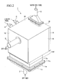
- FIG. 2 is an external perspective view of the evaporator 1
- FIG. 3 is a disassembled perspective view of the same
- FIG. 4 is a perspective view showing the evaporator 11 with a part of an outer plate thereof removed.
- the evaporator 1 includes a closed housing 10 of a rectangular box shape.
- a heating fluid inlet pipe 2 is provided at a bottom 11 of this housing 10, a heating fluid outlet pipe 3 is provided in a side plate 12, two fluid fuel nozzles 4 and 4 are provided in a side plate 13, and a vaporized fuel outlet pipe 5 is provided in a top plate 16.
- the bottom 11 of the housing 10 includes: a filter case 11b which houses a filter 11a; a heating fluid inlet cover 11e which is coupled to a bottom flange 11c of the filter case 11b via a gasket 11d; and a heating fluid receiving box 11f which is arranged on substantially the same plane as the filter 11a and coupled to the filter case 11b.
- the heating fluid inlet pipe 2 is coupled and fixed to the heating fluid inlet cover 11e. Since the heating fluid receiving box 11f is opened in an upper part thereof, a gas is made unable to flow between the heating fluid receiving box 11f and the filter 11a and the filter case 11b.
- the heating fluid outlet pipe 3 is coupled and fixed to a heating fluid outlet hole 12a of the side plate 12.
- Both the two liquid fuel nozzles 4 and 4 extend axial lines thereof horizontally and are arranged at the same height in parallel with each other. Base ends of the liquid fuel nozzles 4 are projected to the outside from the side plate 13, and tip sides thereof are inserted into the housing 10 from holes 13a and 13a of the side plate 13.
- the vaporized fuel outlet pipe 5 is coupled to a flange portion 16b, which is coupled and fixed to a vaporized fuel outlet hole 16a of the top plate 16, via a gasket 16c.
- a heat exchange unit 20 is housed inside this housing 10.
- the heat exchange unit 20 is formed in a rectangular box shape.
- the heat exchange unit 20 is set with the bottom thereof coupled on the filter case 11b and the heating fluid receiving box 11f and is set with a predetermined clearance between the heat exchange unit 20 and the four side plates 12, 13, 14 and 15 and the top plate 16 of the housing 10.
- This clearance forms a heat retaining chamber (heat retaining unit) 17 through which the heated gas flows.
- an opening 11g is formed on the side plate 14 side of the heating fluid receiving box 11f, and the inside of the heating fluid receiving box 11f and the heat retaining chamber 17 communicate with each other via this opening 11g.
- the heating fluid outlet pipe 3 provided on the side plate 12 communicates with this heat retaining chamber 17.
- FIG. 5 is an external perspective view of the heat exchange unit 20
- FIG. 6 is a disassembled perspective view thereof
- FIG. 7 is a longitudinal sectional view thereof
- Fig. 8 is a perspective view showing the inside of the heat exchange unit 20.
- the heat exchange unit 20 includes a casing 21 of a rectangular box shape.
- the casing 21 has a bottom plate 22, a stepped skirt 23, a shell plate 24 formed by bending a plate material in a C shape, and two side plates 25 and 26.
- the bottom plate 22 is joined to the bottom of the skirt 23, a lower opening of the skirt 23 is closed, side plate portions 24a and 24b of the shell plate 24 are joined to the upper end of the skirt 23, and the side plates 25 and 26 are joined to the upper part of the skirt 23 and the shell plate 24, whereby a closed space is formed inside the casing 21.
- a cut groove 27 is provided from a top plate portion 24c to the middle of both the side plate portions 24a and 24b in the shell plate 24.
- the inside space of the casing 21 is sectioned into an evaporation unit 30 and a superheating unit 50 by a partitioning plate 28 inserted in and fixed to this cut groove 27.
- a capacity of the evaporation unit 30 is set larger than a capacity of the superheating unit 50.
- Both the evaporation unit 30 and the superheating unit 50 are constituted by a heat exchanger and have completely the same structure.
- the evaporation unit 30 includes an external cylinder assembly 31, which partitions a heating fluid passage and a heated fluid passage, and a large number of internal cylinders 40, which are inserted into the inside of the external cylinder assembly 31.
- the external cylinder assembly 31 includes a bent plate 33, which is formed by bending one metal plate in a comb-teeth shape, and two side plates 34, which are joined to openings of a comb-teeth shape formed on both sides of the bent plate 33 and close the openings.
- the external cylinder assembly 31 has a form in which a large number of external cylinders 32 of a flattened cylindrical shape with tips thereof closed are arranged at a fixed interval, and base ends side of all the external cylinders 32 are coupled.
- a fin 36 with a section of substantially a triangular corrugated shape are fixed in a clearance between the adjacent external cylinders 32 with projecting portions thereof extending in an axial direction of the external cylinders 32.
- the fin 36 is locked and positioned by projected portions 32a, which project on lower outer surfaces of the external cylinders 32, at lower ends thereof, and are fixed with projecting portions thereof in contact with the outer surfaces of the external cylinders 32.
- the internal cylinder 40 is formed in a flattened cylindrical shape and is opened at both ends in an axial direction.
- the internal cylinder 40 includes a large number of outer projections 41 projecting to the outside and a large number of inner projections 42 projecting to the inside.
- the outer projections 41 are uniformly distributed and arranged substantially over the entire area of the outer surface of the internal cylinder 40
- the inner projections 42 are uniformly distributed and arranged substantially over the entire area of the outer surface of the internal cylinder 40.
- the inner projections 42 are arranged to be opposed to each other in the internal cylinder 40, and the opposed inner projections 42 are abutted against each other.
- a catalyst layer 43 which is formed with, for example, a Pt oxidation catalyst carried on a honeycomb carrier, is provided in a tip portion where the inner projections 42 are not provided.
- one internal cylinder 40 is inserted in each external cylinder 32 of the external cylinder assembly 31 such that the outer projections 41 of the internal cylinder 40 is in abutment with the inner surface of the external cylinder 32 in an inserted state, whereby the clearance between the internal cylinder 40 and the external cylinder 31 is maintained constant.
- the superheating unit 50 is constituted in the same manner. As shown in FIGS. 6, 7 and 8, the superheating unit 50 includes an external cylinder assembly 51, which is formed by joining side plates in openings on both sides of a bent plate and has a large number of external cylinders 52, and an internal cylinder 60 of a flattened cylindrical shape opened at both ends, which is inserted in each external cylinder 52. In the internal cylinder 60, outer projections 61 and inner projections 62 are provided and a catalyst layer 63 is also provided. In this catalyst layer 63, a purification catalyst (Pt, Pd, Rh, etc.) preferable for emission purification for carbon monoxide (CO) or the like is carried. Note that, although not shown in the figure, in the superheating unit 50, a fin is also provided between adjacent external cylinders 52 and 52, and projections for positioning of the fin are provided on the lower outer surface of the external cylinders 52.
- both the external cylinder assembly 31 of the evaporation unit 30 and the external cylinder assembly 51 of the superheating unit 50 are arranged with axial directions of the external cylinders 32 and 52 set in the vertical direction (center of gravity direction).
- the external cylinder assembly 31 of the evaporation unit 30 and the external cylinder assembly 51 of the superheating unit 50 are arranged with the projecting portions of the fin 36 in the evaporation unit 30 and the fin of the superheating unit 50 also extending in the vertical direction (center of gravity direction).
- the external cylinder assembly 31 of the evaporation unit 30 and the external cylinder assembly 51 of the superheating unit 50 are arranged with the above-described partition plate 28 nipped between them with a direction, in which the external cylinders 32 are adjacent to each other, and a direction, in which the external cylinders 52 are adjacent to each other, set in an identical direction.
- lower ends on a side, where the external cylinder assembly 31 and the external cylinder assembly 51 are adjacent to each other, are joined with each other, and a lower end of the partition plate 28 is fixed in a position apart from this connecting portion A upwards by a predetermined length.
- the external cylinder assembly 31 of the evaporation unit 30 and the external cylinder assembly 51 of the superheating unit 50 are joined to the skirt 23 of the casing 21, and the internal cylinders 40 are joined to the bottom plate 22.
- a large number of oblong holes 22a, in which the internal cylinders 40 of the evaporation unit 30 are inserted, are provided in parallel with each other at a predetermined interval in an area where the housing 10 is coupled to the filter case 11b, and a large number of oblong holes 22b, in which the internal cylinders 60 of the superheating unit 50 are inserted, are provided in parallel with each other in an area where the housing 10 is coupled to the heating fluid receiving box 11f.
- periphery forming portions of these holes 22a and 22b are raised to the outside.
- the respective cylinders 40 of the evaporation unit 30 are inserted in the holes 22a of the bottom plate 22 at base ends thereof through the inside of the skirt 23 and are fixed to the periphery forming portions of the holes 22a by bar rings. Furthermore, the external cylinder assembly 31 of the evaporation unit 30 is covered over the internal cylinders 40 such that the respective internal cylinders 40 are inserted in the corresponding external cylinders 32, and the lower end (base end) of the external assembly 31 is joined and fixed to the upper end of the skirt 23. In a state in which the external cylinder assembly 31 and the internal cylinders 40 are fixed in this way, the tips of the internal cylinders 40 are apart from tip closing portions 32b of the external cylinders 32 by a predetermined length.
- FIG. 11 is a disassembled perspective view of the evaporation unit 30 viewed from the bottom, portions to which the superheating unit 50 corresponds in the bottom plate 22 and the skirt 23 are not shown in this figure.
- the above-description is applied to the superheating unit 50 as well.
- the respective cylinders 60 of the superheating unit 50 are inserted in the holes 22b of the bottom plate 22 at base ends thereof through the inside of the skirt 23 and are fixed to the periphery forming portions of the holes 22a by bar rings.
- the external cylinder assembly 51 of the superheating unit 30 is covered over the internal cylinders 60 such that the respective internal cylinders 60 are inserted in the corresponding external cylinders 52, and the lower end (base end) of the external assembly 51 is joined and fixed to the upper end of the skirt 23.
- the tips of the internal cylinders 60 are apart from tip closing portions 52b of the external cylinders 52 by a predetermined length.
- the respective external cylinders 32 are cantilevered at the base ends thereof and form free ends at the tip sides thereof.
- the respective external cylinders 52 are cantilevered at the base ends thereof and form free ends at the tip sides thereof
- the respective internal cylinders 60 are cantilevered at the base ends thereof and form free ends at the tip sides thereof. Therefore, even in the case in which the external cylinder assemblies 31 and 51 and the internal cylinders 40 and 60 thermally expand due to heat applied to them, since the respective external cylinders 32 and 52 and the respective internal cylinders 40 and 60 extend to the tip sides, thermal stress is not caused.
- the external cylinder assemblies 31 and 51 are fixed to the skirt 23, and the partition plate 28 is fixed between both the external cylinder assemblies 31 and 51 in this way. Then, the shell plate 24 of the casing 21 is covered over the external cylinder assemblies 31 and 51. At this point, the partition plate 28 is fit in the cut groove 27 of the shell plate 24. Moreover, the partition plate 28 is joined to the shell plate 24 in the cut groove 27, whereby the cut groove 27 is closed.
- liquid fuel nozzles 4 are inserted between the top plate portion 24c of the shell plate 24 of the casing 21 and the external cylinder assembly 31 piercing through the side plate portions 24a of the shell plate 24.
- the liquid fuel nozzles 4 are arranged with an axial direction thereof set in the same direction as the direction in which the external cylinders 32 are adjacent to each other in the external cylinder assembly 31.
- a vaporized fuel outlet hole 24d is formed in the top plate portion 24c corresponding to the superheating unit 50 in the casing 21.
- a cylinder 24e is joined to this vaporized fuel outlet hole 24d.
- this cylinder 24e is connected to the vaporized fuel outlet hole 16a of the top plate 16 in the housing 10.
- the inside of the external cylinder assemblies 31 and 51 forms a heating fluid passage, and the outside of the external cylinder assemblies 31 and 51 forms a heated fluid passage.
- a heating fluid passage 71 which turns around from the inside to the outside of the internal cylinder 40 at the inner tip of each external cylinder 32, is formed inside the external cylinder assembly 31 of the evaporation unit 30, and a heating fluid passage 72, which turns around from the outside to the inside of the internal cylinder 60 at the inner tip of each external cylinder 52, is formed inside the external cylinder assembly 51 of the superheating unit 50.
- an upstream end of the heating fluid passage 71 i.e., a base end periphery of the internal cylinder 40
- an upstream end of the heating fluid passage 72 i.e., a base end periphery of the internal cylinder 60
- each internal cylinder 40 of the evaporation unit 30 communicates with the heating fluid inlet pipe 2 via the filter 11a, the filter case 11b, and the heating fluid inlet cover 11e.
- the base end of each internal cylinder 60 of the superheating unit 50 communicates with an inner space of the heating fluid receiving box 11f.
- these heated fluid passages 81 and 82 communicate with each other through a space between the lower end of the partition plate 28 and the connecting portion A of the external cylinder assemblies 31 and 51.
- the heated fluid passage 81 of the evaporation unit 30 is generally surrounded by the external cylinders 32
- the heated fluid passage 82 of the superheating unit 50 is generally surrounded by the external cylinders 52 of the superheating unit 50.
- the heated fluid passage 81 of the evaporation unit 30 is generally surrounded by the heating fluid passage 71 of the evaporation unit 30, and the heated fluid passage 82 of the superheating unit 50 is generally surrounded by the heating fluid passage 72 of the superheating unit 50.
- an off-gas exhausted from the fuel cell 110 is supplied to the heated fluid inlet pipe 2 as a heating gas, and a liquid fuel as a heated fluid is supplied to the liquid fuel nozzles 4.
- the heating gas supplied to the heating fluid inlet pipe 2 is filtered by the filter 11a, and then flows in each internal cylinder 40 of the evaporation unit 30 and flows through the heating fluid passage 71.
- the heating gas, having flowed in each internal cylinder 40 flows upwards in the center of gravity direction along the axial direction in the internal cylinder 40.
- hydrogen in the heating gas is combusted, and the heating gas changes to a high-temperature heating gas.
- the heating gas passes through the catalyst layer 43 and is exhausted from the tip of the internal cylinder 40, the heating gas bumps against the tip closing portion 32b of the external cylinder 32 to reverse a direction of flow by 180 degrees and moves around to the outside of the internal cylinder 40, flows downwards in the center of gravity direction along the axial direction of the internal cylinder 40 between the external cylinder 32 and the internal cylinder 40, and flows in the space between the skirt 23 and the bottom plate 22.
- the high-temperature heating gas flows downwards in the center of gravity direction on the outside of the internal cylinder 40, a part of the heat of the heating gas is transferred to the external cylinder 32 and is further transferred to the fin 36 arranged between the external cylinders 32.
- the high-temperature heating gas is sufficiently agitated by the outer projections 41 while the heating gas flows through the heating fluid passage 71 between the external cylinder 32 and the internal cylinder 40, whereby heat transfer performance is improved.
- the heating gas having flowed in the space between the skirt 23 and the bottom plate 22, flows through the heating fluid passage 72 of the superheating unit 50.
- the heating gas flows in the space between the external cylinder 52 and the internal cylinder 60 of the superheating unit 50 from the space between the skirt 23 and the bottom plate 22, and flows upwards in the center of gravity direction along the axial direction of the internal cylinder 60 in the space between the external cylinder 52 and the internal cylinder 60.
- the heating gas bumps against the tip closing portion 52b of the external cylinder 52 to reverse a direction of flow by 180 degrees and moves around to the inside of the internal cylinder 60, flows downwards in the center of gravity direction along the axial direction in the internal cylinder 60 through the catalyst layer 63, and flows out to the heating fluid receiving box 11f of the casing 21 from the base end opening of the internal cylinder 60. Then, when the heating gas flows upwards in the center of gravity direction on the outside of the internal cylinder 60, a part of the heat of the heating gas is transferred to the external cylinder 52 and is further transferred to the fin arranged between the external cylinders 52 and 52.
- the purification catalyst When the heating gas flows through the catalyst layer 63, unreacted hydrogen contained in the heating gas is subjected to catalytic combustion by the purification catalyst carried in the catalyst layer 63, and gas temperature rises. A part of the heat of this heating gas is transferred through the internal cylinder 60 to heat the heating gas flowing on the outside of the internal cylinder 60.
- the purification catalyst subjects the emission to catalytic combustion to purify the heating gas.
- the heating gas having flowed out to the heating fluid receiving box 11f, flows in the heat retaining chamber 17 between the housing 10 and the casing 21 through the upper opening 11g of the heating fluid receiving box 11f and is exhausted from the heating fluid outlet pipe 3 while flowing along the periphery of the casing 21.
- the liquid fuel supplied to the liquid fuel nozzles 4 is injected obliquely downwards from a large number of injection holes (not shown) provided in the liquid fuel nozzles 4 in the inside of the casing 21 and flows in the space between the external cylinders 32 in the evaporation unit 30, that is, the heated fluid passage 81.
- the free end side of the external cylinder 32 is an inlet port for the liquid fuel.
- the liquid fuel injected from the liquid fuel nozzles 4 changes to droplets, flows in the heated fluid passage 81 from the space between the external cylinders 32, and adheres to the fin 36 to flow down along the surface thereof or passes through gap formed in the fin 36 to fall.
- the liquid fuel flows downwards in the center of gravity direction in the heated fluid passage 81.
- the liquid fuel adhered to the surface of the external cylinder 32 and the surface of the fin 36 exchanges heat with the high-temperature heating gas flowing through the heating fluid passage 71 between the external cylinder 32 and the internal cylinder 40 via the external cylinder 32 and the fin 36 to instantly vaporize into vaporized fuel.
- the liquid fuel which passes through the gaps in the fin 36 to fall, also vaporizes into vaporized fuel under the high-temperature atmosphere in the heated fluid passage 81 while the liquid fuel falls in the heated fluid passage 81.
- the fin 36 is provided in the heated fluid passage 81 of the evaporation unit 30, the liquid fuel tends to spread widely, and a surface area of a heating surface is extremely large. As a result, vaporization of the liquid fuel is facilitated.
- collided portions portions against which the liquid fuel has collided
- the liquid fuel having scattered collides against the fin 36 near the collided portions again. Since the liquid fuel repeats such collision, a frequency of contact of the liquid fuel on the surface of the fin 36 serving as the heating surface increases, and vaporization of the liquid fuel is facilitated.
- a temperature distribution over the entire fin 36 in the heated fluid passage 81 is made substantially uniform by the heat transfer of the fin 36.
- the entire area of the heated fluid passage 81 can be used as a heat exchange unit, and the liquid fuel can be efficiently converted into a vaporized fuel.
- this evaporator 1 can vaporize the liquid fuel extremely efficiently and promptly and is extremely superior in response.
- the fin 36 in multiple stages in the vertical direction and to arrange projecting portions in an offset manner in the vertically arranged fin 36. In this way, the frequency of collision of the liquid fuel against the fin 36 further increases, and vaporization of the liquid fuel is further facilitated.
- the heated fluid passage 81 is generally surrounded by the external cylinders 32. In other words, the heated fluid passage 81 is generally surrounded by the heating fluid passage 71.
- heat radiation from vaporized fuel flowing through the heated fluid passage 81 can be controlled, and a decrease in the temperature of generated vaporized fuel can be prevented.
- the vaporized fuel generated in this way falls in the center of gravity direction in the heated fuel passage 81.
- the vaporized fuel having reached the lower part of the heated fluid passage 81 in the evaporation unit 30 passes the lower side of the partition plate 28 in the casing 21, flows in the heated fluid passage 82 of the superheating unit 50, and flows upwards in the center of gravity direction in the respective spaces among the external cylinders 52 in the superheating unit 50. Then, while the vaporized fuel flows upwards in the center of gravity direction in the heated fluid passage 82, the vaporized fuel exchanges heat with the heating gas, which flows in the heating fluid passage 72 between the external cylinders 52 and the internal cylinders 60, via the fin provided among the external cylinders 52, and is further heated.
- the vaporized fuel having reached the upper part in the casing 21 in the superheating unit 50 is exhausted to the vaporized fuel outlet pipe 5 from the vaporized fuel outlet hole 24d of the casing 21 through the cylinder 24e and the vaporized fuel outlet hole 16a of the housing 10 and is supplied to the reformer 101 via a pipe which is not shown.
- the vaporized fuel flows from the evaporation unit 30 to the superheating unit 50, and the heating gas also flows from the evaporation unit 30 to the superheating unit 50. That is, the fuel stream and the heating gas flow in parallel with each other.
- the vaporized fuel and the heating gas are allowed to flow as parallel flows, changes in a degree of superheating of the vaporized fuel with respect to a change in a flow rate of the heating gas can be controlled, and changes in the temperature of the vaporized fuel can be controlled.
- both the flowing directions of the vaporized fuel and the heating gas are the direction along the axial direction of the external cylinders 32 and 52 and the internal cylinders 40 and 60 (center of gravity direction) in both the evaporation unit 30 and the superheating unit 50, compared with the case in which the flowing directions of the vaporized fuel and the heating gas are crossed, temperature distribution in the horizontal direction of the external cylinders 32 and 52 and the internal cylinders 40 and 60 can be made substantially uniform. Therefore, thermal distortion can be prevented from occurring in the horizontal direction of the external cylinders 32 and 52 and the internal cylinders 40 and 60, and thermal stress can be prevented from being caused.
- the heat retaining chamber 17 provided between the housing 10 and the casing 21 surrounds the periphery of the heat exchange unit 20, and the heating gas flowing through the heat retaining chamber 17 has sufficiently high temperature even after the heat exchange.
- the heating gas in the heat retaining chamber 17 acts as a heat retaining layer to control heat radiation from the heat exchange unit 20 and prevents the temperature of the generated vaporized fuel from falling.
- both the respective external cylinders 32 and the respective internal cylinders 40 of the evaporation unit 30 and the respective external cylinders 52 and the respective internal cylinders 60 of the superheating unit 50 are cantilevered at the base ends thereof and have free ends at the tip sides thereof.
- the cylinders extend to the tip sides, respectively, whereby thermal distortion can be absorbed, and thermal stress can be prevented from being caused. Therefore, thickness and weight of the external cylinders 32 and 52 and the internal cylinders 40 and 60 can be reduced.
- the catalyst layers 43 and 63 are provided at tip portions of the internal cylinders 40 and 60, a part where high temperature is generated by catalytic combustion can be placed away from the base portions which are the cantilevered sides of the internal cylinders 40 and 60, and thermal stress applied to the connecting portions of the internal cylinders 40 and 60 and the bottom plate 22 can be reduced. Therefore, durability of the evaporator 1 is improved.
- vaporized fuel outlet pipe 5 is provided in the top plate 16 of the housing 10, discharge of droplets, which is not preferable for a reaction in the reformer 101, can be prevented. Moreover, droplets, which are generated at the time when operation of the evaporator 1 is stopped, can be prevented from being discharged to the reformer 101.
- this evaporator 1 in the case in which this evaporator 1 is mounted on a fuel cell automobile, it is probable that the orientation of the evaporator 1 will incline more or less.
- the evaporator 1 inclines, in this evaporator 1, since the fin 36 provided in the heated fluid passage 81 of the evaporator 30 acts as a partition wall, the liquid fuel can be prevented from flowing only in a part of the area in the heated fluid passage 81. As a result, since a substantial heat transfer area can be prevented from being changed, evaporation performance can be maintained constant.
- the heat exchange unit 20 it is also possible for flowing directions of the fuel and the vaporized fuel to be set to be the same as described above, and only flow direction of the heating gas is set to the opposite of the above-described case.
- the heating gas it is also possible for the heating gas to flow in from the internal cylinder 60 of the superheating unit 50, to flow through from the inside to the outside of the internal cylinder 60, and to flow through the outside of the internal cylinder 40 of the evaporation unit 30, and then to flow to the inside of the internal cylinder 40.
- the vaporized fuel flows from the evaporation unit 30 to the superheating unit 50, and the heating gas flows from the superheating unit 50 to the evaporation unit 30. That is, the vaporized fuel and the heating gas flow in parallel with each other.
- the temperature of the vaporized fuel can be brought close to the temperature of the heating gas, and response of temperature control of the vaporized fuel is improved.
- the catalyst layer 63 of the superheating unit 50 is located on the upstream side in the flowing direction of the heating gas, a caloric value of the heating gas in the catalyst layer 63 of the superheating unit 50 can be increased.
- the vaporized fuel can receive a large quantity of heat from the catalyst layer 63 near the terminal end of the superheating unit 50, and response of temperature control of the vaporized fuel can be significantly improved.
- FIG. 15A shows a fin of a rectangular corrugated shape in section
- FIG. 15B shows a so-called helibome fin
- FIG. 15C shows a porous plate fin
- FIG. 15D shows a so-called cerate fin
- FIG. 15E shows a so-called louver fin. Heat exchange efficiency can be further improved by adopting these fins.
- FIGS. 16 and 17 a second embodiment of the evaporator in accordance with the present invention will be described with reference to FIGS. 16 and 17.
- the evaporator in the second embodiment can be used instead of the evaporator 1 in the fuel improving system shown in FIG. 1.
- an evaporator 1A includes a housing 200 of a rectangular box shape.
- a heating fluid inlet 201 is provided in a front part of the housing 200, and a heating fluid outlet 202 and a vaporized fuel outlet 203 are provided in a rear part the housing 200.
- the inside of the housing 200 forms an evaporation unit (heat exchanger) 250.
- the heating fluid inlet 201 is provided in a heating fluid inlet hood 204 which is fixed to a front plate 200a of the housing 200. Inside the housing 200, a partition plate 205 is set in the vertical direction in parallel with the front plate 200a so as to close the housing 200 leaving a bottom clearance 206.
- a large number of oblong holes 207 which are made to be longer in the vertical direction, are provided at a predetermined interval in parallel with each other.
- a large number of oblong holes 208 which are made to be longer in the vertical direction, are also provided in association with the oblong holes 207, respectively.
- the oblong holes 208 of the partition plate 205 are formed slightly larger than the oblong holes 207.
- the heating fluid inlet hood 204 is provided so as to surround all the oblong holes 207 of the front plate 200a.
- One internal cylinder 220 is attached to each of the oblong holes 207 of the front plate 200a, and one external cylinder 230 is attached to each of the oblong holes 208 of the partition plate 205.
- the external cylinder 230 is formed in a flattened cylindrical shape in the vertical direction, has an axis extending straightly from a front side to a rear side of the housing 200 horizontally, and opens only at a base end and closes at a tip thereof.
- the base end is inserted and fixed to the oblong hole 208 of the partition plate 205, and the tip is extended close to a rear plate 200b of the housing 200.
- the internal cylinder 220 is formed in a flattened cylindrical shape in the vertical direction, has an axis extending straightly from a front side to a rear side of the housing 200 horizontally, and opens at both ends. A base end thereof is inserted and is fixed to the oblong hole 207 of the front plate 200a, and a tip side thereof is inserted in the inside of the external cylinder 230 from the oblong hole 208.
- a predetermined clearance is secured between an outer peripheral surface of the internal cylinder 220 and an inner peripheral surface of the external cylinder 230, and the tip of the internal cylinder 220 is located apart from the a tip closing portion 231 of the external cylinder 230 by a predetermined length.
- the respective external cylinders 320 are cantilevered at base ends thereof and form free ends at the tip sides thereof, and the respective internal cylinders 220 are also cantilevered at base ends thereof and form free ends at the tip sides thereof.
- the internal cylinder 220 and the external cylinder 230 thermally expand due to heat applied to the cylinders, since the internal cylinder 220 and the external cylinder 230 extend to the tip sides, respectively, thermal stress is not caused.
- a partition plate 209 which is arranged apart from the external cylinder 230, provided on a lower side of the external cylinder 230 is provided in the inside of the housing 200.
- the partition plate 209 is coupled to a lower end of the partition plate 205 and both inner side surfaces of the housing 200 and is bent obliquely upwards in the vicinity of the tip of the external cylinder 230 to be coupled to the rear plate 200b of the housing 200.
- a coupling portion with the rear plate 200b converges on a periphery of the vaporized fuel outlet 203.
- a downward-extended plate 210 which is extended downwardly from a top plate 200c of the housing 200, is provided in a position a predetermined length apart to the rear surface side of the housing 200 from the partition plate 205. Both sides of the downward-extended plate 210 are coupled to both the inner side surfaces of the housing 200. A lower end of the downward-extended plate 210 is located above and apart from the external cylinder 230, and a partition plate 211 is coupled to the lower end of the downward-extended plate 210.
- the partition plate 211 is coupled to both the inner side surfaces of the housing 200 and is bent obliquely downwards in the vicinity of the tip of the external cylinder 230 to be coupled to the rear plate 200b of the housing 200.
- a coupling portion with the rear plate 200b converges on a periphery of the vaporized fuel outlet 203.
- both the two liquid fuel nozzles 213 and 213 extend such that the axes thereof are arranged horizontally and in a direction perpendicular to a direction along which the external cylinders 230 are arranged to be adjacent to each other.
- the two liquid fuel nozzles 213 and 213 are arranged at the same height in parallel with each other, and are set above and apart from the external cylinder 230.
- a heating fluid passage 241 which turns around from the inside to the outside of the internal cylinder 220 at the tip of the internal cylinder 220, is formed, a heated fluid passage 242 is formed between the adjacent external cylinders 230 and 230 and between the partition plates 209 and 211, a heating fluid discharge passage 243 is formed between the partition plate 209 and the housing 200. Furthermore, the heating fluid passage 241 communicates with the heating fluid inlet 201, the heated fluid passage 242 communicates with the vaporized fuel outlet 203, and the heating fluid discharge passage 243 communicates with the heating fluid outlet 202.
- an off-gas exhausted from the fuel cell 110 is supplied to the heating fluid inlet 201 as a heating gas, and a liquid fuel as a heated fluid is supplied to the liquid fuel nozzles 213.
- the heating gas supplied to the heating fluid inlet 201 flows in the respective internal cylinders 220 and flows through the heating fluid passage 241.
- the heating gas having flowed in the respective internal cylinders 220, flows toward the tip of the internal cylinder 220 along the axial direction in the internal cylinder 220.
- hydrogen in the heating gas is combusted, and the heating gas changes to a high-temperature heating gas.
- the heating gas bumps against the tip closing portion 231 of the external cylinder 230 to reverse a direction of flow by 180 degrees and moves around to the outside of the internal cylinder 220, and flows toward the base end between the external cylinder 230 and the internal cylinder 220. Then, when the high-temperature heating gas flows outside the internal cylinder 220, a part of the heat of the heating gas is transferred to the external cylinder 230.
- the heating gas bumps against the front plate 200a of the housing 200, the heating gas passes the bottom clearance 206 of the housing 200 to flow in the heating fluid discharge passage 243, and flows to the rear side of the housing 200 in the heating fluid discharge passage 243 to be discharged from the heating fluid outlet 203.
- the liquid fuel supplied to the liquid fuel nozzles 213 is injected obliquely downwards from a large number of injection holes (not shown) provided in the liquid fuel nozzles 313 in the space 212 formed in an upper part on the front side in the housing 200.
- a flow inlet of the heated fluid flowing the outside of the external cylinder 230 is provided on the outside in the flat direction of the external cylinder 230, whereby the heated fluid flows in a direction crossing the heating gas flowing on the inside of the external cylinder 230.
- the liquid fuel injected from the liquid fuel nozzles 313 changes to droplets and adheres to the surfaces of the respective external cylinders 230.
- the liquid fuel adhered to the surface of the external cylinder 230 flows down along the surface of the external cylinder 230 and flows downwards in the center of gravity direction in the heated fluid passage 242. Then, the liquid fuel adhered to the surface of the external cylinder 230 exchanges heat with the high-temperature heating gas, which flows in the heating fluid passage 241 between the external cylinder 230 and the internal cylinder 220, via the external cylinder 230 to instantly vaporize into a vaporized fuel.
- the heated fluid passage 242 is generally surrounded by the external cylinders 230. In other words, the heated fluid passage 242 is generally surrounded by the heating fluid passage 241.
- heat radiation from the vaporized fuel flowing through the heated fluid passage 242 can be controlled, and the temperature of the generated vaporized fuel can be prevented from falling.
- the vaporized fuel generated in this way flows horizontally toward the rear side of the housing 200 in the heated fluid passage 242. During this flow, the vaporized fuel also exchange heat with the high-temperature heating gas, which flows in the heating fluid passage 241 between the external cylinder 230 and the internal cylinder 220, via the external cylinder 230. As a result, the vaporized fuel is heated.
- the vaporized fuel having reached the terminal end of the heated fuel passage 242 is discharged from the vaporized fuel outlet 203 of the housing 200 and supplied to the reformer 101 via a pipe which is not shown.
- both the respective internal cylinders 220 and the respective external cylinders 230 are cantilevered at the base ends thereof and form free ends at the tip sides.
- the cylinders extend to the tip sides, respectively, whereby thermal distortion can be absorbed, and thermal stress is hardly caused. Therefore, thickness and weight of the internal cylinder 220 and the external cylinder 230 can be reduced.
- the catalyst layer 221 is provided at the tip side of the internal cylinder 220, a part where high temperature is generated by catalytic combustion can be placed away from the base portion which is the cantilevered side of the internal cylinder 220, and thermal stress applied to the connecting portion of the internal cylinder 220 and the front plate 220a can be reduced. Therefore, durability of the evaporator 1A is improved.
- rigidity of the front plate 200a can be set low.
- rigidity of the partition plate 205 which cantilevers the external cylinder 230, can be set low. As a result, thickness of not only the front plate 200a and the partition plate 205 but also of the housing can be reduced, and weight of the evaporator 1A can be reduced.
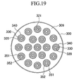
- FIGS. 18 and 19 An evaporator in the third embodiment can be used instead of the evaporator 1 in the fuel reforming system shown in FIG. 1.
- an evaporator 1B includes a housing 300 of substantially a cylindrical shape, which has an axis extending in the vertical direction.
- a heating fluid inlet 301 is provided in a bottom 300a of the housing 300
- a heating fluid outlet 302 and a liquid fuel inlet 303 are provided in a body 300b
- a vaporized fuel outlet 304 is provided at a top 300c.
- the inside of the housing 300 forms an evaporation unit (heat exchanger) 360.
- partition plates 311, 312, 313 and 314, which are horizontal in a surface direction thereof, are set apart from each other in the vertical direction.
- the partition plate 311 is arranged in the vicinity of the bottom 300a of the housing 300. A large number of circular holes 311 a are pierced and formed in this partition plate 311.
- the partition plate 312 is arranged above and apart from the partition plate 311. A large number of circular holes 312a are also pierced and formed in this partition plate 312 concentrically with the holes 311 a of the partition plate 311. The holes 312a of the partition plate 312 is formed to have a larger diameter than the holes 311 a of the partition plate 311.
- the partition plate 313 is arranged further above and apart from the partition plate 312.
- a large number of circular holes 313a are also pierced and formed concentrically with the holes 311a of the partition plate 311.
- the holes 313a of the partition plate 313 is formed to have a larger diameter than the holes 312a of the partition plate 312.
- the partition plate 314 is arranged further above and apart from the partition plate 313 and in a position close to the top 300c.
- a large number of circular holes 314a are also pierced and formed concentrically with the holes 311 a of the partition plate 311.
- the holes 314a of the partition plate 314 are formed so as to have a larger diameter than the holes 313a of the partition plate 313.
- the heating fluid inlet 301 communicates with a space (hereinafter referred to as a heating fluid dispersion chamber) 305 formed on a lower side of the partition plate 311.
- the heating fluid outlet 302 communicates with a space (hereinafter referred to as a heating fluid collecting chamber) 306 formed between the partition plate 311 and the partition plate 312.
- the liquid fuel inlet 304 communicates with a space (hereinafter referred to as an evaporation chamber) 307 formed between the partition plate 312 and the partition plate 313.
- the vaporized fuel outlet 304 communicates with a space (hereinafter referred to as a vaporized fuel collecting chamber) 308 formed on an upper side of the partition plate 314.
- One internal cylinder 320 is attached to each of the holes 311a of the partition plate 311, and one external cylinder 330 is attached to each of the holes 312a of the partition plate 312.
- One outermost cylinder 340 is attached to each of the holes 313a of the partition plate 313 and the holes 314a of the partition plate 314 corresponding to the holes 313a.
- the outermost cylinder 340 is formed in a cylindrical shape with both ends opened and its axis is vertical. A base end thereof is inserted and fixed to the hole 313a of the partition plate 313 and a tip side thereof pierces through the hole 314a of the partition plate 314 and extends further upwards.
- the external cylinder 330 is formed in a cylindrical shape with only a base end thereof opened and a tip thereof closed and its axis is vertical.
- the base end is inserted and fixed to the hole 312a of the partition plate 312 and a tip side thereof is inserted in the inside of the outermost cylinder 340 from the hole 313a of the partition plate 313.
- the tip is located at substantially the same height as the tip of the outermost cylinder 340.
- the external cylinder 330 and the outermost cylinder 340 attached in this way are arranged concentrically, and a heated fluid passage 352 of an annular shape in section is formed between an outer peripheral surface of the cylinder 330 and an inner peripheral surface of the outermost cylinder 340. This heated fluid passage 352 communicates with the evaporation chamber 307 at a lower end thereof and communicates with the vaporized fuel collecting chamber 308 at an upper end thereof.
- the internal cylinder 320 is formed in a cylindrical shape with both ends thereof opened and its axis is vertical. A base end thereof is inserted and fixed to the hole 311 a of the partition plate 311 and a tip side thereof is inserted in the inside of the external cylinder 330 from the hole 312a of the partition plate 312. A tip of the internal cylinder 320 is located apart from a tip closing portion 331 of the external cylinder 330 by a predetermined length.
- the internal cylinder 320 and the external cylinder 330 attached in this way are arranged concentrically. A predetermined clearance is secured between an outer peripheral surface of the internal cylinder 320 and an inner peripheral surface of the external cylinder 330.
- a heating fluid passage 351 which turns around from the inside to the outside of the internal cylinder 320 at the tip of the internal cylinder 320, is formed inside the external cylinder 330.
- This heating fluid passage 351 communicates with the heating fluid dispersion chamber 305 at one end thereof (lower opening of the internal chamber 320) and communicates with the heating fluid collecting chamber 306 at the other end (lower opening of the external cylinder 330).
- the respective external cylinders 330 are cantilevered at base ends thereof and form free end at tip sides thereof, and the respective internal cylinders 320 are also cantilevered at base ends thereof and form free ends at tip sides thereof.
- the internal cylinder 320 and the external cylinder 330 expand due to heat applied to the cylinders, the internal cylinder 320 and the external cylinder 330 extend to the tip sides, respectively, and thermal stress is not caused.
- a catalyst layer 321 which is formed with, for example, a Pt oxidation catalyst carried on a honeycomb carrier, is provided.
- a space formed between the partition plate 313 and the partition plate 314 and on the outside of the outermost cylinder 340 is completely closed and constitutes a heat insulating chamber 309 in which the air filled in the inside thereof acts as a heat insulating layer.
- an off-gas exhausted from the fuel cell 110 is supplied to the heating fluid inlet 301 as a heating gas, and the liquid fuel as the heated fluid is supplied to the liquid fuel inlet 303.
- the heating gas supplied to the heating fluid inlet 301 flows in the respective internal cylinders 320 via the heating fluid dispersion chamber 305 and flows through the heating fluid passage 351.
- the heating gas having flowed in the respective internal cylinder 320, flows upwards in the center of gravity direction in the internal cylinder 320.
- hydrogen in the heating gas is combusted, and the heating gas changes to a high-temperature heating gas.
- the heating gas bumps against the tip closing portion 331 of the external cylinder 330 to reverse the direction of flow by 180 degrees and moves around to the outside of the internal cylinder 320, and flows downwards in the center of gravity direction between the external cylinder 330 and the internal cylinder 320. Then, when the high-temperature heating gas flows outside the internal cylinder 320, a part of the heat of the heating gas is transferred to the external cylinder 330.
- the heating gas having flowed downwards in the center of gravity direction between the external cylinder 330 and the internal cylinder 320, is exhausted to the heating fluid collecting chamber 306 from the lower end opening of the external cylinder 330, and is further exhausted from the heating fluid outlet 302. Then, when the heating gas passes through the heating fluid collecting chamber 306, a part of the heat of the heating gas is transferred to the partition plate 312.
- the liquid fuel supplied from the liquid fuel inlet 303 to the evaporation chamber 307 spreads over the surface of the partition plate 312.
- the base end side of the external cylinder 330 is an inlet port for the liquid fuel.
- the liquid fuel having spread over the surface of the partition plate 312, exchanges heat with the heating gas of the heating fluid collecting chamber 306 via the partition plate 312 so as to be converted into a vaporized fuel.
- This vaporized fuel flows in the heated fluid passage 352 from an opening between the outermost cylinder 340 and the external cylinder 330 and flows upwards in the center of gravity direction in the heated fluid passage 352. During this flow, the vaporized fuel also exchanges heat with the high-temperature heating gas flowing in the heating fluid passage 351 between the external cylinder 330 and the internal cylinder 320. As a result, the vaporized fuel is heated.
- the heated fluid passage 352 is surrounded by the heat insulating chamber 309 containing the air as a heat insulating layer, heat radiation from the vaporized fuel passing through the heated fluid passage 352 can be controlled, and the temperature of the generated vaporized fuel can be prevented from falling.
- the vaporized fuel having reached the upper end of the heated fluid passage 352 is exhausted to the vaporized fuel collecting chamber 308 from the upper opening of the outermost cylinder 340 and is further exhausted from the vaporized fuel outlet 304 of the housing 300 to be supplied to the reformer 101 via a pipe which is not shown.
- both the respective internal cylinders 320 and the respective external cylinders 330 are cantilevered at the base ends thereof and form free ends at the tip sides.
- the cylinders extend to the tip sides, respectively, whereby thermal distortion can be absorbed, and thermal stress is hardly caused. Therefore, thickness and weight of the internal cylinder 320 and the external cylinder 330 can be reduced.
- the catalyst layer 321 is provided at the tip side of the internal cylinder 320, a part where high temperature is generated by catalytic combustion can be placed away from the base portion which is the cantilevered side of the internal cylinder 320, and thermal stress applied to the connecting portion of the internal cylinder 320 and the partition plate 311 can be reduced. Therefore, durability of the evaporator 1B is improved.
- the internal cylinder 320, the external cylinder 330, and the outermost cylinder 340 are circular, these cylinders can be constituted by a commercially available pipe, and the structure of the evaporator 1B is also simplified.
- the vaporized fuel outlet 304 is provided at the top 300c of the housing 300, discharge of droplets, which is not preferable for a reaction in the reformer 101, can be prevented. Moreover, droplets, which are generated at the time when operation of the evaporator 1B is stopped, can be prevented from being discharged to the reformer 101.
- the external cylinder is set along the vertical direction (center of gravity direction).
- the external cylinder may be set in the horizontal direction.
- a setting direction for the external cylinder can be determined from layouts of the heat exchanger and the evaporator.
- the evaporator of the present invention is not limited to one which vaporizes a liquid fuel.
- the heat exchanger can be applied to devices other than the evaporator.
- the heat exchanger of the present invention even if the external cylinder and the internal cylinder thermally expand when used under a high-temperature environment, the external cylinder and the internal cylinder can absorb thermal distortion by extending to the free end side because these cylinders are cantilevered. Therefore, an excellent effect is realized in that thermal stress is not caused, and durability of the heat exchanger is improved. In addition, since thermal stress is not caused, rigidity of the external cylinder and the internal cylinder as well as components associated with these cylinders can be set low. There is also an effect that thickness and weight of these components can be reduced.
- temperature distribution of the external cylinder and the internal cylinder in a direction perpendicular to the axial direction of the external cylinder and the internal cylinder can be made substantially uniform.
- thermal distortion can be prevented from occurring, and thermal stress can be prevented from being caused.
- heat radiation from a fluid flowing on the outside of the external cylinder can be controlled, and a fall in the temperature of the fluid can be controlled.
- a heat transfer area of the external cylinder is increased by the existence of the fin, and heat transfer performance is improved.
- the fluid passage on the outside of the external cylinder is divided into smaller parts by the fin, in particular, in the case in which the fluid flowing on the outside of the external cylinder is a liquid, the liquid never flows only on the one side of the fluid passage, and stable heat exchange can be performed between the heating fluid and the heated fluid.
- the clearance between the external cylinder and the internal cylinder can be maintained constant, the fluid flowing on the inside of the external cylinder can be made to flow uniformly.
- the fluid flowing on the inside of the external cylinder can be agitated by the projected parts, heat transfer performance is improved.
- the external cylinder since the external cylinder has the flattened cylindrical shape, it becomes possible to insert a fin, which is generally used in a heat exchanger, between adjacent external cylinders.
- a fin which is generally used in a heat exchanger
- the evaporator of the present invention even if the external cylinder and the internal cylinder of the evaporation unit thermally expand, the external cylinder and the internal cylinder can absorb thermal distortion by extending to the free end side because these cylinders are cantilevered. Therefore, an excellent effect is realized in that thermal stress is not caused, and durability of the evaporator is improved. In addition, since thermal stress is not caused, rigidity of the external cylinder and the internal cylinder as well as components associated with these cylinders can be set low. There is also an effect that thickness and weight of these components can be reduced. Moreover, there is also an effect in that a heat capacity of the evaporator is reduced by the reduction in thickness and weight, and a start-up time of the evaporator is reduced.
- vaporized fuel generated by the evaporation unit can be thermally exchanged with the heating gas in the superheating unit, vaporized fuel of higher temperature can be generated.
- the vaporized fuel and the heating gas flow in parallel with each other, i.e., both the vaporized fuel and the heating gas flow from the evaporation unit to the superheating unit.
- changes in a degree of superheating of the vaporized fuel with respect to a change in a flow rate of the heating gas can be controlled, and changes in the temperature of the vaporized fuel can be controlled.
- the vaporized fuel flows from the evaporation unit to the superheating unit, and the heating gas flow in opposing direction with respect to the vaporized fuel, i.e., flows from the superheating unit to the evaporation unit.
- the temperature of the vaporized fuel can be brought close to the temperature of the heating gas, and response of temperature control of the vaporized fuel is improved.
- a combustible substance in the heating gas to be supplied to the heating fluid passage of the evaporation unit can be subjected to catalytic combustion to increase the temperature of the heating gas.
- a quantity of generation of the vaporized fuel can be increased, and performance of the evaporator is improved.
- a combustible substance in the heating gas flowing through the heating fluid passage of the superheating unit can be subjected to catalytic combustion to increase the temperature of the heating gas.
- the temperature of the vaporized fuel can be increased.
- the supporting portion of the internal cylinder can be provided apart from a part heated by catalytic combustion. Thus, thermal stress applied to the supporting portion can be reduced.
- heat of the evaporation unit can be retained using exhaust heat of the heating gas, and heat radiation from the evaporation unit can be controlled.
- performance of the evaporator is improved.
- a heat exchanger includes: a casing (21); an external cylinder (32) which is arranged inside the casing (21) with a clearance formed between the external cylinder (32) and an inner surface of the casing (21) and is supported in a cantilevered manner, has a closed end portion (32b), and forms a first fluid passage (81) between the external cylinder (32) and the casing (21); and an internal cylinder (40) which is arranged inside the external cylinder (32) with a clearance formed between the internal cylinder (40) and an inner surface of the external cylinder (32) and is supported in a cantilevered manner, is open at both ends, and forms a second fluid passage (71), which is turned around at the closed end portion (32b) of the external cylinder (32), between the internal cylinder (40) and the external cylinder (32).
Landscapes
- Chemical & Material Sciences (AREA)
- Engineering & Computer Science (AREA)
- Chemical Kinetics & Catalysis (AREA)
- Organic Chemistry (AREA)
- Combustion & Propulsion (AREA)
- Physics & Mathematics (AREA)
- Mechanical Engineering (AREA)
- Sustainable Development (AREA)
- Electrochemistry (AREA)
- General Chemical & Material Sciences (AREA)
- Manufacturing & Machinery (AREA)
- Thermal Sciences (AREA)
- Sustainable Energy (AREA)
- General Engineering & Computer Science (AREA)
- Life Sciences & Earth Sciences (AREA)
- Health & Medical Sciences (AREA)
- General Health & Medical Sciences (AREA)
- Inorganic Chemistry (AREA)
- Fuel Cell (AREA)
- Heat-Exchange Devices With Radiators And Conduit Assemblies (AREA)
Abstract
Description
Claims (20)
- A heat exchanger comprising:a casing (21);an external cylinder (32) which is arranged inside the casing (21) with a clearance formed between the external cylinder (32) and an inner surface of the casing (21) and is supported in a cantilevered manner, has a closed end portion (32b), and forms a first fluid passage (81) between the external cylinder (32) and the casing (21); andan internal cylinder (40) which is arranged inside the external cylinder (32) with a clearance formed between the internal cylinder (40) and an inner surface of the external cylinder (32) and is supported in a cantilevered manner, is open at both ends, and forms a second fluid passage (71), which is turned around at the closed end portion (32b) of the external cylinder (32), between the internal cylinder (40) and the external cylinder (32).
- The heat exchanger according to claim 1,
wherein one of the first fluid passage (81) and the second fluid passage (71) is a heating fluid passage and the other is a heated fluid passage. - The heat exchanger according to one of claims 1 and 2,
wherein a fluid flowing inside the external cylinder (32) flows turning around on the inside of the closed end portion (32b) of the external cylinder (32), and a fluid flowing outside the external cylinder (32) flows along an axial direction of the external cylinder (32). - The heat exchanger according to any one of claims 1 to 3, comprising plural external cylinders (32),
wherein fluid passages are formed between plural external cylinders (32). - The heat exchanger according to one of claims 1 and 2, further comprising a fin (36) provided on the outside of the external cylinder (32).
- The heat exchanger according to any one of claims 1 to 3, further comprising plural projecting portions (41) formed on an outer surface of the internal cylinder (40).
- The heat exchanger according to any one of claims 1 to 3, comprising a plurality of an external cylinder (32) and an internal cylinder (40) disposed in the external cylinder (32),
wherein the external cylinders (32), each of which has a flattened cylindrical shape and is supported in a cantilevered manner such that an end thereof is fixed, are coupled to each other at the ends thereof, and
wherein each of the internal cylinders (40) has a flattened cylindrical shape and is supported in a cantilevered manner such that an end thereof, corresponding to the end of each of the external cylinders (32), is fixed. - The heat exchanger according to any one of claims 1,2, and 7, further comprising an inlet port for a fluid flowing on the outside of the external cylinder (32) provided at a free-end side of the external cylinder (32).
- The heat exchanger according to claim 7,
wherein the external cylinders (32) comprise a corrugated plate (33) formed by bending a single plate so as to be corrugated, and side plates (34) closing both lateral sides of the corrugated plate (33). - The heat exchanger according to claim 7,
wherein an inlet port for a fluid flowing outside the external cylinders (32) is disposed outside the external cylinders (32) and close to sharply curved portions of the external cylinders (32). - The heat exchanger according to any one of claims 1 to 3,
wherein both the external cylinder (330) and the internal cylinder (320) are formed in a cylindrical shape, and a fluid passage (352) with an annular cross-section is formed around the external cylinder (330). - An evaporator comprising an evaporation unit (30) including the heat exchanger according to any one of claims 1 to 11,
wherein one of the first fluid passage (81) and the second fluid passage (71) is a heating fluid passage, and the other is a heated fluid passage, and
wherein the heated fluid is a fluid fuel and vaporized fuel generated by vaporizing the fluid fuel, and the heating fluid is a heating gas. - The evaporator according to claim 12, further comprising a superheating unit (50) which heats the vaporized fuel generated by the evaporation unit (30) by heat exchange with the heating gas, and the superheating unit (50) comprises the heat exchanger according to any one of claims 1 to 11.
- The evaporator according to claim 12,
wherein the heating gas flows from the heating fluid passage (71) of the evaporation unit (30) to the heating fluid passage (72) of the superheating unit (50). - The evaporator according to claim 12,
wherein the heating gas flows from the heating fluid passage (72) of the superheating unit (50) to the heating fluid passage (71) of the evaporation unit (30). - The evaporator according to any one of claims 12 to 15,
wherein a catalyst (43) is provided in the heating fluid passage (71) of the heat exchanger constituting the evaporation unit (30). - The evaporator according to any one of claims 13 to 16,
wherein a catalyst (63) is provided in the heating fluid passage (72) of the heat exchanger constituting the superheating unit (50). - The evaporator according to one of claims 16 and 17,
wherein the heating fluid passage is formed inside of the external cylinder (32), and the catalyst (43 or 63) is provided inside the internal cylinder (40 or 60). - The evaporator according to claim 18,
wherein the catalyst (43 or 63) is provided at a free-end side of the internal cylinder (40 or 60). - The evaporator according to one of claims 12 and 13, further comprising a heat retaining unit (17) disposed around the evaporation unit (30),
wherein the heating gas, which is exhausted through the heating fluid passage (71) of the evaporation unit (30), flows through the heat retaining unit (17).
Applications Claiming Priority (2)
| Application Number | Priority Date | Filing Date | Title |
|---|---|---|---|
| JP2003104105 | 2003-04-08 | ||
| JP2003104105A JP3961443B2 (en) | 2003-04-08 | 2003-04-08 | Evaporator |
Publications (3)
| Publication Number | Publication Date |
|---|---|
| EP1467168A2 true EP1467168A2 (en) | 2004-10-13 |
| EP1467168A3 EP1467168A3 (en) | 2005-09-14 |
| EP1467168B1 EP1467168B1 (en) | 2010-12-01 |
Family
ID=32866722
Family Applications (1)
| Application Number | Title | Priority Date | Filing Date |
|---|---|---|---|
| EP04008379A Expired - Lifetime EP1467168B1 (en) | 2003-04-08 | 2004-04-06 | Heat exchanger and evaporator |
Country Status (5)
| Country | Link |
|---|---|
| US (1) | US7530389B2 (en) |
| EP (1) | EP1467168B1 (en) |
| JP (1) | JP3961443B2 (en) |
| CA (1) | CA2463279C (en) |
| DE (1) | DE602004030298D1 (en) |
Cited By (1)
| Publication number | Priority date | Publication date | Assignee | Title |
|---|---|---|---|---|
| WO2013114773A1 (en) * | 2012-01-30 | 2013-08-08 | Honda Motor Co., Ltd. | Fuel cell module |
Families Citing this family (26)
| Publication number | Priority date | Publication date | Assignee | Title |
|---|---|---|---|---|
| FR2887020B1 (en) * | 2005-06-09 | 2007-08-31 | Air Liquide | PLATE HEAT EXCHANGER WITH EXCHANGE STRUCTURE FORMING MULTIPLE CHANNELS IN A PASSAGE |
| JP2008059770A (en) * | 2006-08-29 | 2008-03-13 | Kyocera Corp | Heat exchanger for exhaust heat recovery and fuel cell system |
| TWM335720U (en) * | 2008-02-14 | 2008-07-01 | Celsia Technologies Taiwan Inc | Homeothermy plate and support structure thereof |
| US20100006268A1 (en) * | 2008-07-14 | 2010-01-14 | Meyer Iv George Anthony | Vapor chamber and supporting structure of the same |
| JP5705414B2 (en) * | 2009-03-30 | 2015-04-22 | アイシン精機株式会社 | Fuel cell system |
| DE102010050519A1 (en) | 2010-11-08 | 2012-05-10 | Nft Nanofiltertechnik Gmbh | heat exchangers |
| US9279626B2 (en) * | 2012-01-23 | 2016-03-08 | Honeywell International Inc. | Plate-fin heat exchanger with a porous blocker bar |
| ES2615907T3 (en) | 2012-10-09 | 2017-06-08 | Nuvera Fuel Cells, Inc. | Bipolar plate design for use in conductive cooled electrochemical cells |
| WO2015030777A1 (en) | 2013-08-29 | 2015-03-05 | Delphi Technologies, Inc. | Heater and method of operating |
| US9647291B2 (en) | 2013-08-29 | 2017-05-09 | Delphi Technologies, Inc. | Heater and supporting structure thereof |
| US9698434B2 (en) * | 2013-08-29 | 2017-07-04 | Delphi Technologies, Inc. | Heater |
| US9520601B2 (en) | 2013-08-29 | 2016-12-13 | Delphi Technologies, Inc. | Heater and method of operating |
| US9494024B2 (en) | 2013-08-29 | 2016-11-15 | Delphi Technologies, Inc. | Heater and method of operating |
| US9379394B2 (en) * | 2013-11-15 | 2016-06-28 | Delphi Technologies, Inc. | Heater with a fuel cell stack assembly and a combustor and method of operating |
| US9531020B2 (en) | 2013-11-15 | 2016-12-27 | Delphi Technologies, Inc. | Method of operating a heater |
| US9640829B2 (en) | 2013-12-06 | 2017-05-02 | Delphi Technologies, Inc. | Heater and method of operating |
| US9328596B2 (en) | 2014-01-21 | 2016-05-03 | Delphi Technologies, Inc. | Heater and method of operating |
| US20150280257A1 (en) * | 2014-03-31 | 2015-10-01 | Delphi Technologies, Inc. | Heater with a Fuel Cell Stack Assembly and a Combustor and Method of Operating |
| US9476283B2 (en) | 2014-04-10 | 2016-10-25 | Delphi Technologies, Inc. | Geothermic heater system |
| CN104390508A (en) * | 2014-11-05 | 2015-03-04 | 中国船舶重工集团公司第七�三研究所 | Porous wavy fin template fin heat exchanger |
| US9559379B2 (en) | 2015-03-19 | 2017-01-31 | Delphi Technologies, Inc. | Heater |
| US10151176B2 (en) | 2015-04-07 | 2018-12-11 | Aptiv Technologies Limited | Heater and supporting structure thereof |
| JP6454660B2 (en) | 2016-05-30 | 2019-01-16 | パナソニック株式会社 | Solvent separation method and solvent separation apparatus |
| KR102674815B1 (en) * | 2021-11-08 | 2024-06-12 | 엘지전자 주식회사 | Fuel cell system |
| CN120237388A (en) * | 2023-12-30 | 2025-07-01 | 岳秀兰 | Electric vehicle endurance system consisting of battery formation, injection, ventilation and cooling system |
| CN118718971B (en) * | 2024-09-04 | 2024-11-22 | 潍坊兴泰电气有限公司 | Bromine production device and method based on mother liquor heating method |
Family Cites Families (27)
| Publication number | Priority date | Publication date | Assignee | Title |
|---|---|---|---|---|
| US784716A (en) * | 1903-01-26 | 1905-03-14 | Gardner T Voorhees | Heat-interchanging apparatus. |
| US2117337A (en) * | 1934-11-03 | 1938-05-17 | Lobl Karel | Evaporator |
| US2134058A (en) * | 1936-06-16 | 1938-10-25 | Griscom Russell Co | Heat exchanger |
| US2155666A (en) * | 1936-12-04 | 1939-04-25 | Silas C Wead | Heat exchange unit |
| US2372079A (en) * | 1941-04-19 | 1945-03-20 | American Locomotive Co | Heat exchanger |
| US2392255A (en) * | 1943-10-20 | 1946-01-01 | John J Mcandrews | Evaporator |
| US3118495A (en) | 1956-11-12 | 1964-01-21 | David Dalin | Method of cleaning heat exchangers |
| GB971902A (en) | 1959-11-27 | 1964-10-07 | Int Combustion Holdings Ltd | Improvements in or relating to nuclear reactors |
| US3196198A (en) * | 1961-11-13 | 1965-07-20 | Owens Illinois Glass Co | Method and apparatus for molding plastic articles |
| US3360036A (en) | 1965-08-20 | 1967-12-26 | Earl F Holyfield | Heat exchanger |
| JPS5257551A (en) | 1975-11-06 | 1977-05-12 | Ishikawajima Harima Heavy Ind Co Ltd | Recuperator for use of radiation pipe |
| US4163474A (en) | 1976-03-10 | 1979-08-07 | E. I. Du Pont De Nemours And Company | Internally finned tube |
| US4258785A (en) * | 1980-02-08 | 1981-03-31 | Borg-Warner Corporation | Heat exchanger interplate fitting |
| GB8331543D0 (en) | 1983-11-25 | 1984-01-04 | Wb Combustion Ltd | Recuperator |
| FI76699C (en) * | 1986-06-25 | 1988-12-12 | Ahlstroem Oy | INDUNSTARE AV ROERTYP. |
| JPS63179401A (en) | 1987-01-20 | 1988-07-23 | Nippon Telegr & Teleph Corp <Ntt> | Testing machine for deflection of magnetic disk |
| JPH0619965Y2 (en) * | 1988-01-22 | 1994-05-25 | サンデン株式会社 | Heat exchanger |
| US5735342A (en) * | 1996-05-17 | 1998-04-07 | Nitta; Minoru | Heat exchanger |
| ES2192698T3 (en) * | 1996-12-05 | 2003-10-16 | Showa Denko Kk | HEAT EXCHANGER. |
| US6032728A (en) * | 1998-11-12 | 2000-03-07 | Livernois Research & Development Co. | Variable pitch heat exchanger |
| CA2272804C (en) * | 1999-05-28 | 2004-07-20 | Long Manufacturing Ltd. | Heat exchanger with dimpled bypass channel |
| JP3554921B2 (en) | 1999-11-05 | 2004-08-18 | 本田技研工業株式会社 | Fuel evaporator |
| JP3603274B2 (en) * | 1999-11-05 | 2004-12-22 | 本田技研工業株式会社 | Fuel evaporator |
| US6467536B1 (en) * | 1999-12-22 | 2002-10-22 | Visteon Global Technologies, Inc. | Evaporator and method of making same |
| US6568466B2 (en) * | 2000-06-23 | 2003-05-27 | Andrew Lowenstein | Heat exchange assembly |
| US6497856B1 (en) * | 2000-08-21 | 2002-12-24 | H2Gen Innovations, Inc. | System for hydrogen generation through steam reforming of hydrocarbons and integrated chemical reactor for hydrogen production from hydrocarbons |
| JP4479117B2 (en) * | 2001-03-15 | 2010-06-09 | アイシン精機株式会社 | Fuel reformer |
-
2003
- 2003-04-08 JP JP2003104105A patent/JP3961443B2/en not_active Expired - Fee Related
-
2004
- 2004-04-05 CA CA2463279A patent/CA2463279C/en not_active Expired - Fee Related
- 2004-04-06 EP EP04008379A patent/EP1467168B1/en not_active Expired - Lifetime
- 2004-04-06 US US10/819,851 patent/US7530389B2/en not_active Expired - Fee Related
- 2004-04-06 DE DE602004030298T patent/DE602004030298D1/en not_active Expired - Lifetime
Cited By (1)
| Publication number | Priority date | Publication date | Assignee | Title |
|---|---|---|---|---|
| WO2013114773A1 (en) * | 2012-01-30 | 2013-08-08 | Honda Motor Co., Ltd. | Fuel cell module |
Also Published As
| Publication number | Publication date |
|---|---|
| CA2463279C (en) | 2010-08-10 |
| EP1467168B1 (en) | 2010-12-01 |
| EP1467168A3 (en) | 2005-09-14 |
| US7530389B2 (en) | 2009-05-12 |
| JP2004309031A (en) | 2004-11-04 |
| JP3961443B2 (en) | 2007-08-22 |
| CA2463279A1 (en) | 2004-10-08 |
| US20040200605A1 (en) | 2004-10-14 |
| DE602004030298D1 (en) | 2011-01-13 |
Similar Documents
| Publication | Publication Date | Title |
|---|---|---|
| EP1467168B1 (en) | Heat exchanger and evaporator | |
| US7575611B2 (en) | Fuel processor for use in a fuel cell system | |
| US8114173B2 (en) | Hydrogen generator and method of operating the same | |
| US6531102B1 (en) | Fuel reforming apparatus | |
| JP5705414B2 (en) | Fuel cell system | |
| WO2004007355A1 (en) | Evaporator | |
| JP2006170484A (en) | Heat exchanger | |
| JP2001089105A (en) | Fuel reformer | |
| JP3913624B2 (en) | Evaporator | |
| JP6596856B2 (en) | Reformed water evaporator and power generator | |
| JP3889328B2 (en) | Evaporator | |
| JPH0450246B2 (en) | ||
| US8821832B2 (en) | Fuel processor for use with portable fuel cells | |
| JP5198091B2 (en) | Fuel cell reformer | |
| JP5250885B2 (en) | Gas treatment device for fuel cell | |
| JP4470293B2 (en) | Evaporator and fuel reformer for mounting on vehicle | |
| JP2005281097A (en) | Reformer | |
| JP2001135331A (en) | Fuel evaporator | |
| JP4231172B2 (en) | Fuel evaporator | |
| JP3554922B2 (en) | Fuel evaporator | |
| JPH1143304A (en) | Reforming unit | |
| JPH0891803A (en) | Reforming device for engine methanol | |
| JP3582059B2 (en) | Fuel evaporator | |
| JP2006143558A (en) | Reformer | |
| JP4412689B2 (en) | Fuel processor for fuel cell |
Legal Events
| Date | Code | Title | Description |
|---|---|---|---|
| PUAI | Public reference made under article 153(3) epc to a published international application that has entered the european phase |
Free format text: ORIGINAL CODE: 0009012 |
|
| AK | Designated contracting states |
Kind code of ref document: A2 Designated state(s): AT BE BG CH CY CZ DE DK EE ES FI FR GB GR HU IE IT LI LU MC NL PL PT RO SE SI SK TR |
|
| AX | Request for extension of the european patent |
Extension state: AL HR LT LV MK |
|
| PUAL | Search report despatched |
Free format text: ORIGINAL CODE: 0009013 |
|
| AK | Designated contracting states |
Kind code of ref document: A3 Designated state(s): AT BE BG CH CY CZ DE DK EE ES FI FR GB GR HU IE IT LI LU MC NL PL PT RO SE SI SK TR |
|
| AX | Request for extension of the european patent |
Extension state: AL HR LT LV MK |
|
| 17P | Request for examination filed |
Effective date: 20060102 |
|
| AKX | Designation fees paid |
Designated state(s): DE FR GB |
|
| 17Q | First examination report despatched |
Effective date: 20090729 |
|
| GRAP | Despatch of communication of intention to grant a patent |
Free format text: ORIGINAL CODE: EPIDOSNIGR1 |
|
| GRAS | Grant fee paid |
Free format text: ORIGINAL CODE: EPIDOSNIGR3 |
|
| RIN1 | Information on inventor provided before grant (corrected) |
Inventor name: YAMAGAMI, TAKESHI Inventor name: HANAI, SATOSHI Inventor name: YOSHIDA, NOBUYOSHI |
|
| GRAA | (expected) grant |
Free format text: ORIGINAL CODE: 0009210 |
|
| RAP1 | Party data changed (applicant data changed or rights of an application transferred) |
Owner name: HONDA MOTOR CO., LTD. |
|
| AK | Designated contracting states |
Kind code of ref document: B1 Designated state(s): DE FR GB |
|
| REG | Reference to a national code |
Ref country code: GB Ref legal event code: FG4D |
|
| REF | Corresponds to: |
Ref document number: 602004030298 Country of ref document: DE Date of ref document: 20110113 Kind code of ref document: P |
|
| PGFP | Annual fee paid to national office [announced via postgrant information from national office to epo] |
Ref country code: DE Payment date: 20110330 Year of fee payment: 8 Ref country code: FR Payment date: 20110426 Year of fee payment: 8 |
|
| PGFP | Annual fee paid to national office [announced via postgrant information from national office to epo] |
Ref country code: GB Payment date: 20110406 Year of fee payment: 8 |
|
| PLBE | No opposition filed within time limit |
Free format text: ORIGINAL CODE: 0009261 |
|
| STAA | Information on the status of an ep patent application or granted ep patent |
Free format text: STATUS: NO OPPOSITION FILED WITHIN TIME LIMIT |
|
| 26N | No opposition filed |
Effective date: 20110902 |
|
| REG | Reference to a national code |
Ref country code: DE Ref legal event code: R097 Ref document number: 602004030298 Country of ref document: DE Effective date: 20110902 |
|
| GBPC | Gb: european patent ceased through non-payment of renewal fee |
Effective date: 20120406 |
|
| REG | Reference to a national code |
Ref country code: FR Ref legal event code: ST Effective date: 20121228 |
|
| PG25 | Lapsed in a contracting state [announced via postgrant information from national office to epo] |
Ref country code: GB Free format text: LAPSE BECAUSE OF NON-PAYMENT OF DUE FEES Effective date: 20120406 |
|
| REG | Reference to a national code |
Ref country code: DE Ref legal event code: R119 Ref document number: 602004030298 Country of ref document: DE Effective date: 20121101 |
|
| PG25 | Lapsed in a contracting state [announced via postgrant information from national office to epo] |
Ref country code: FR Free format text: LAPSE BECAUSE OF NON-PAYMENT OF DUE FEES Effective date: 20120430 |
|
| PG25 | Lapsed in a contracting state [announced via postgrant information from national office to epo] |
Ref country code: DE Free format text: LAPSE BECAUSE OF NON-PAYMENT OF DUE FEES Effective date: 20121101 |