EP1466292B1 - Positionnement d'une camera et systeme retroactif de confirmation - Google Patents
Positionnement d'une camera et systeme retroactif de confirmation Download PDFInfo
- Publication number
- EP1466292B1 EP1466292B1 EP03703870A EP03703870A EP1466292B1 EP 1466292 B1 EP1466292 B1 EP 1466292B1 EP 03703870 A EP03703870 A EP 03703870A EP 03703870 A EP03703870 A EP 03703870A EP 1466292 B1 EP1466292 B1 EP 1466292B1
- Authority
- EP
- European Patent Office
- Prior art keywords
- plane
- bars
- lens
- image
- light
- Prior art date
- Legal status (The legal status is an assumption and is not a legal conclusion. Google has not performed a legal analysis and makes no representation as to the accuracy of the status listed.)
- Revoked
Links
Images


Classifications
-
- G—PHYSICS
- G06—COMPUTING; CALCULATING OR COUNTING
- G06K—GRAPHICAL DATA READING; PRESENTATION OF DATA; RECORD CARRIERS; HANDLING RECORD CARRIERS
- G06K7/00—Methods or arrangements for sensing record carriers, e.g. for reading patterns
- G06K7/10—Methods or arrangements for sensing record carriers, e.g. for reading patterns by electromagnetic radiation, e.g. optical sensing; by corpuscular radiation
- G06K7/10544—Methods or arrangements for sensing record carriers, e.g. for reading patterns by electromagnetic radiation, e.g. optical sensing; by corpuscular radiation by scanning of the records by radiation in the optical part of the electromagnetic spectrum
- G06K7/10821—Methods or arrangements for sensing record carriers, e.g. for reading patterns by electromagnetic radiation, e.g. optical sensing; by corpuscular radiation by scanning of the records by radiation in the optical part of the electromagnetic spectrum further details of bar or optical code scanning devices
- G06K7/10881—Methods or arrangements for sensing record carriers, e.g. for reading patterns by electromagnetic radiation, e.g. optical sensing; by corpuscular radiation by scanning of the records by radiation in the optical part of the electromagnetic spectrum further details of bar or optical code scanning devices constructional details of hand-held scanners
-
- G—PHYSICS
- G06—COMPUTING; CALCULATING OR COUNTING
- G06K—GRAPHICAL DATA READING; PRESENTATION OF DATA; RECORD CARRIERS; HANDLING RECORD CARRIERS
- G06K2207/00—Other aspects
- G06K2207/1011—Aiming
Definitions
- the present invention relates generally to data acquisition equipment, and in particular, but not exclusively, to a system to provide positioning and reading feedback to a user of a data acquisition device.
- Bar code scanners typically read and decode a linear bar code, which can either be printed directly on an item of interest or can be printed on a label and then attached to the item.
- the most familiar type of linear bar code usually consists of a series of black bars of differing widths, spaced apart from each other by white space.
- Two-dimensional codes are usually read by machine vision systems, which essentially capture a digital image of the two-dimensional code, and then proceed to analyze that image to extract the information contained in the code.
- One chronic difficulty that has emerged in the reading of two-dimensional codes is that of ensuring that the machine vision scanner acquires an image of the code from which it can extract information.
- One of the difficulties in acquiring a suitable image is ensuring that the code itself is positioned within the field of view of the scanner, and that the image is in focus.
- Roustaei describes a scanner system including a targeting feature that uses several beams of light to indicate the positions of some of the boundaries of the system's field of view.
- Roustaei's system suffers from various disadvantages. Among other things, the system is limited to indicating only the positions of two of the boundaries of the field of view, or, alternatively, the positions of the four corners of the field of view. Roustaei provides no indication of where the center of the field of view lies.
- Roustaei Since the center of the field of view is the optimal position for a target whose image is to be captured, Roustaei provides sub-optimal results because it forces the user to either guess or visually interpolate the center of the field of view. Moreover, Roustaei targeting feature only tells a user when the target is in the field of view, but does not provide any information to assist the user in positioning the target at the proper focus distance. Finally, Roustaei's targeting feature employs very complex optical components, such as lasers, fiber optics, beam splitters, and complex configurations of mirrors and lenses. The nature and complexity of the components involved leads to high costs and, inevitably, to poor system reliability.
- the user With the LED's on the chassis of the scanner, the user must continually look away from the code he or she is trying to scan to look at the LEDs to see if they light up. This is a distraction for the user, and takes their attention away from keeping the code within the field of view of the scanner.
- US 6 060 722 discloses an optical device for use with optoelectronic readers, and which has a pattern generator for generating an aiming pattern which coincides with the field of view of the imaging device.
- EP 1 172 756 also discloses an optical device which provides visual indication of a reading area of a coded information reader.
- an apparatus comprising; a base capable of receiving a camera including a lens; and a projector coupled to the base and adapted to project a plurality of beams of light onto a plane positioned at a focus distance from the base, wherein the projections of the beams of light on the plane are geometric shapes, and wherein an intersection of the geometric shapes is at the center of the field of view of the lens independent of the distance between the lens and the plane when the lens is installed on the base.
- the invention also provides a process comprising: projecting a first light beam onto a plane, wherein the projection of the first light beam on the plane is a first geometric shape; projecting a second light beam onto the plane, wherein the projection of the second light beam on the plane is a second geometric shape; and aligning the first and second beams such that an intersection of the first and second geometric shapes is at the center of the field of view of a lens of a camera, independently of the distance between the lens and the plane.
- Embodiments of a system and method for providing positioning and scanning feedback to the user of a machine-vision system are described herein.
- numerous specific details are described to provide a thorough understanding of embodiments of the invention.
- One skilled in the relevant art will recognize, however, that the invention can be practiced without one or more of the specific details, or with other methods, components, materials, etc.
- well-known structures, materials, or operations are not shown or described in detail to avoid obscuring aspects of the invention.
- FIG. 1 illustrates the operation of an embodiment of the invention comprising a machine vision system 10.
- a machine vision system 10 generally includes a camera having optics designed to capture target images (or "targets") to be analyzed, such as two-dimensional bar codes, also known as "matrix" codes. Two-dimensional bar codes are only one example of a target whose image is analyzed using machine vision; other types of targets may also be analyzed.
- the optics are selected based on the physical size of the image to be captured, as well as the distance the system 10 will be placed from the image.
- optics having a long focal length and small field of view will be used; conversely, if a large image close to the system 10 is to be captured, optics having a shorter focal length and larger field of view will be used. Whether the system 10 reads labels at distances A, B, or C depends on the optics inside the system 10.
- the system 10 projects a first light beam 12 and a second light beam 14 toward a plane on which the image is located.
- Both light beams 12 and 14 are shaped to emerge from the system 10 as "flat" beams, such that the projection of each beam on a plane will be in a shape of a bar.
- Both beams 12 and 14 are aligned such that the bars 16 and 18 created by their projection on a plane will intersect each other.
- the beams 12 and 14 are aligned such that the intersection of the bars will be in the center of the field of view of the optics within the system 10, regardless of distance from the system.
- the intersection of the bars will indicate the center of the field of view of the optics within the system.
- the user places the image to be read by the system at the intersection of the bars, the image will be properly positioned to be read by the system.
- the exact nature of the intersection will depend on the distance between the system 10 and the plane on which the bars are projected.
- the bars 16 and 18 form a "V" shape
- the bars 16 and 18 form an "X” shape
- the bars 16 and 18 form a caret (" ⁇ ").
- the shape of the intersection of the bars 16 and 18, thus also gives a user setting up the system 10 feedback regarding the proper focus distance for the image.
- a user can easily position the image to be scanned in the field of view at the proper distance to obtain the optimum focus, so that the camera within the system 10 can obtain a sharp image.
- Figures 2A-2C illustrate one possible embodiment of the relationship between the shape formed by the intersection of the bars 16 and 18 and the focus distance (A, B or C) between the system 10 and the plane.
- different geometric shapes besides bars could also be used, instead of or in addition to the bars, to convey the same field-of-view and focus information.
- polygonal shapes such as squares and triangles could be used, as well as shapes such as circles, etc.
- Each bar 16 and 18 has a first end E and a second end D.
- the bars intersect at point F, which, as explained above, always corresponds to the center of the field of vision of the optics in the system, independent of the distance between the system 10 and the plane.
- the first bar 16 and second bar 18 intersect at or near their first ends E, thus substantially taking the shape of a caret (" ⁇ ").
- ⁇ a caret
- the user knows that the plane on which the bars are projected is a distance C from the system, and that the point F is at the center of the view of the lens within the system.
- the optics are such that the focus distance is distance C
- the user simply adjusts the distance from the system 10 such that the caret-shaped intersection is created, and then positions the image to be captured at or near the intersection F.
- Figure 2B illustrates the intersection of the bars 16 and 18 when the plane on which they are projected is a distance B from the system.
- the bars 16 and 18 intersect substantially in an "X" shape, with the point of intersection F again being the center of the field of view of the optics.
- the bars 16 and 18 intersect so as to substantially bisect each other; in other words, each bar roughly cuts the other in half.
- B is the correct focus distance
- a user adjusts the distance from the system until the X shape is formed and positions the image at point F.
- the image is at the proper distance and in the proper location for scanning by the system.
- Figure 2A illustrates the pattern formed by the bars at a focus distance A from the system 10.
- the bars 16 and 18 intersect each other at or near their second ends D, thus substantially forming a "V" shape.
- FIG. 3 illustrates an embodiment of the internal construction of a machine-vision system 10.
- the system 10 includes a housing comprising an upper half of the housing 20 and a lower half of the housing 22. Contained within the housing are the main or primary components of the system: a base 24 which primarily holds and aligns the optics and other components, an illumination system 26, a front window 28, and an image sensing system 30. Also included within the system 10 are other components 32, which handle functions such as digital signal processing (DSP), input/output (I/O), and the like.
- DSP digital signal processing
- I/O input/output
- the primary function of the base 24 is to support and align the components of the system 10, including the optics 34 (e.g., lenses, apertures, and the like).
- the base 24 comprises a lower portion 36 and an upper portion 38, and has a front 40 and a rear 42.
- the base When the base is in its assembled state with the upper portion mounted on the lower portion 36, the base includes a tubular cavity 44 designed to support and align the optics 34 used by the system.
- the optics 34 reside within the tubular cavity 44 and focus the image to be captured on the image sensor 66 on the image sensing system 30 (see below).
- two relatively smaller tubular cavities 46 are formed when the upper portion 38 is mounted on the lower portion 36.
- a light-emitting diode (LED) 68 is inserted into the rear of each tubular cavity 46, and a beam-forming apparatus is also mounted in each of the tubular cavities 46.
- the beam forming apparatus comprises a slit 70 mounted near the rear of the cavity 46 to form the light beam into a flat beam, coupled with a lens 71 mounted near the front of the cavity 46.
- the lens 71 is designed to collimate the light emerging from the slit, so that it projects from the system 10.
- the LEDs 68 are illuminated light beams travel from the rear end of each cavity 46 through the cavity, through the slit 70, through the lens 71, then through the hole 52 in the illumination board, and out through the front window and on to the plane on to which they are projected.
- the illumination system 26 provides illumination for the target, so that an image of the target can be captured by the image sensor 66.
- the illumination system 26 is mounted on the front 40 of the base 24.
- the illumination system 26 comprises a circuit board 48 having a central hole 50 therein, designed to coincide with the central cavity 44 of the base, when the illumination system 26 is mounted on the front of the base.
- the purpose of the holes 50 and 52 is to allow the light to pass through the illumination system, out the front window 28, and onto the image to be captured.
- the illumination LEDs 54 are red, although other colors may be used in other embodiments, and in other embodiments light sources besides LEDs may be used for illumination.
- the illumination system includes two confirmation LEDs 56, which in this embodiment are green. The confirmation LED's are operatively connected to a signal processing unit; when the signal processing unit indicates that a code has been successfully decoded, both confirmation LEDs blink.
- the primary purpose of the front window 28, in addition to closing and sealing the interior of the system 10, is to diffuse the light emitted by all of the illumination LEDs 54 on the circuit board 48 so that they uniformly illuminate the area where the target will be positioned.
- the front window 28 comprises a substantially flat piece of a material such as of glass or plastic with a coating applied thereto to protect it from scratching and abrasion. Most of the front window 28 is frosted to achieve the diffusion, although the diffusion may also be achieved by, for example, using a plurality of Fresnel lenses ground into a plastic or glass that comprises the front window.
- a central area 58 of the front window is designed to coincide with the hole 50 on the circuit board 48. This central area is transparent to allow light to travel through the front window and the central hole 50, and into the optics 34 contained in the tubular cavity 44 of the base. Thus, the central transparent area 58 in the front window 28 is to allow light to travel without dispersion or dissipation all the way to the image sensor module 30.
- the front window 28 also includes two transparent areas 62 which coincide with the holes 52 in the circuit board 48. The transparent areas 62 allow the beams formed by the LEDs 68 in conjunction with the slit 70 and lens 71 to pass through the front window for protection onto the target plane.
- the transparent areas 58, 60 and 62 may also be shaped such that they refract light to provide further focusing, collimation, or shaping of light traveling through the front window 28.
- the image sensing module 30 comprises a circuit board 64 on which is mounted an image sensor 66.
- the image sensor 66 may be any kind of commercially available sensor, such as a complementary metal oxide semiconductor (CMOS) chip, a charge coupled device (CCD), and the like.
- CMOS complementary metal oxide semiconductor
- CCD charge coupled device
- Also attached to the printed circuit board 64 are a pair of light emitting diodes (LEDs) 68.
- the LEDs 68 are the light sources used to create the beams 12 and 14, which then create the bars 16 and 18 when projected on a plane. In a preferred embodiment, the LEDs 68 emit red light, although other colors are possible.
- LEDs are used as light sources in this particular embodiment, other types of light sources suitable for use in forming the beams 12 and 14 can also be used.
- the LEDs 68 are positioned on the same circuit board 64 with the image sensor, they may instead be positioned elsewhere within the system 10.
- Figure 4 is a frontal elevation of the base 24, in its assembled condition with the upper portion 38 attached to the lower portion 36. Once the upper portion 38 is attached to the lower portion 36, a central cavity 44 is formed. As explained above, the purpose of this central cavity is to support and align the optics, which will be used to capture an image of the target and focus it on the image sensing module 30. In addition, two smaller cavities 46 are formed when the upper half is attached to the lower half. As explained above, the rear ends of the cavities 46 have slits 70 therein which are used to form the light emitted by the LEDs 68 into a flat shape, and the front ends of the cavities 46 contain lenses used to focus or collimate the light emitted from the slits.
- FIG. 5 is a side elevation of the system 10, illustrating its assembled state.
- the base 24 is attached to the lower half of the housing 22 by some fastening means such as screws, clips, etc.
- the image sensing module 30 is mounted onto the rear of the base 24, such that each of the LEDs 68 is inserted into the rear of one of the small tubular cavities 46. In this way, the light emitted by the LED 68 is channeled through the tubular cavity to the slit 70, then through the lens 71. then through a hole in the illumination system 26, and finally out through the front window 28.
- the image sensing module 30 is also mounted to the back of the base such that the image sensor 66 is aligned with the center of the tubular cavity 44 of the base. As explained above, the tubular cavity 44 supports and aligns the optics which focus the image onto the image sensor 66 for capture.
- the illumination system 26 is attached to the front of the base 24, so that the light from the illumination LEDs 54 can be projected out through the front window and onto the target to be captured.
- the front window 28 is positioned at the very front of the unit 10 so it can diffuse the red light emitted by the LEDs 54 and provide uniform illumination of the target.
- the front window has transparent portions to allow the light transmitted from the LED 68 through the smaller tubular cavities 46 to be transmitted onto the target, and also to allow the light from the target to pass unimpeded through the front window 28 and the optics 34, and onto the image sensor 66.
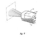
- FIG. 6 illustrates the operation of the image processing confirmation described above.
- the confirmation LEDs 56 located on the illumination system 26 are coupled to the image processing electronics 32. After an image is captured using the image sensor 66, it is processed by digital signal processing (DSP) hardware. If the DSP hardware successfully decodes the image, it sends a signal to the two confirmation LEDs 56. In response to this signal, the confirmation LEDs 56 flash, thus projecting a quick burst of green light onto the plane containing the target and providing feedback to the user that a successful read was accomplished. In this way, the user does not have to take his or her eyes away from the field or the image to know whether a successful read was accomplished, but instead he or she waits for the green flash, which indicates a successful decoding of the label.
- DSP digital signal processing
Landscapes
- Physics & Mathematics (AREA)
- Engineering & Computer Science (AREA)
- Electromagnetism (AREA)
- Artificial Intelligence (AREA)
- Toxicology (AREA)
- General Health & Medical Sciences (AREA)
- Health & Medical Sciences (AREA)
- Computer Vision & Pattern Recognition (AREA)
- General Physics & Mathematics (AREA)
- Theoretical Computer Science (AREA)
- Studio Devices (AREA)
- Radar Systems Or Details Thereof (AREA)
- Image Input (AREA)
- Focusing (AREA)
Claims (15)
- Appareil (10), comprenant :une base (24) capable de recevoir une caméra (10) qui inclut une lentille (34) ; etun projecteur couplé à la base,caractérisé en ce que le projecteur est adapté à projeter une pluralité de faisceaux de lumière sur un plan positionné à une distance focale de la base, dans lequel les projections des faisceaux de lumière sur le plan sont des formes géométriques (16, 18), et dans lequel une intersection (F) des formes géométriques se trouve au centre du champ de vue de la lentille, indépendamment de la distance entre la lentille et le plan quand la lentille et installée sur la base.
- Appareil selon la revendication 1, dans lequel les formes géométriques sont des barres (16, 18).
- Appareil selon la revendication 2, dans lequel la pluralité de barres comprend deux barres, qui incluent une première barre (16) et une seconde barre (18).
- Appareil selon la revendication 3, dans lequel une forme créée par l'intersection de la première et de la seconde barre varie selon la distance focale.
- Appareil selon la revendication 4, dans lequel chacune de la première et de la seconde barre (16, 18) a une première et une seconde extrémité (E, D), et dans lequel :si la première et la seconde barre se recoupent au niveau ou à proximité de leurs deux premières extrémités (E), formant sensiblement une forme en accent circonflexe, la caméra est à une première distance focale ;si la première et la seconde barre (16, 18) se recoupent mutuellement au milieu, la caméra est à une seconde distance focale ; etsi la première et la seconde barre se recoupent mutuellement au niveau ou à proximité de leurs deux secondes extrémités (D), formant sensiblement une forme en V, la caméra est à une troisième distance focale.
- Appareil selon la revendication 1, dans lequel le projecteur comprend un premier et un second projecteur, comprenant chacun :une source de lumière ;un formateur de faisceau positionné entre la source de lumière et le plan, pour former le faisceau émis depuis la source de lumière ; etune lentille pour focaliser le faisceau de lumière émis depuis le formateur de faisceau.
- Appareil selon la revendication 1, comprenant en outre une caméra (10) qui inclut une lentille.
- Appareil selon l'une quelconque des revendications précédentes, comprenant en outre :un processeur d'image pour traiter une image capturée par la caméra ; etun projecteur de confirmation couplé au processeur d'image, tel que le projecteur projette un faisceau de confirmation sur le plan quand le processeur d'image signale au projecteur de confirmation que le processeur d'image a traité l'image.
- Appareil selon la revendication 8, dans lequel le projecteur de confirmation comprend :une source de lumière; etune lentille pour focaliser la lumière émise depuis la source de lumière.
- Appareil selon la revendication 8, dans lequel le faisceau de confirmation clignote instantanément sur le plan.
- Procédé, comprenant :la projection d'un premier faisceau de lumière sur un plan, tel que la projection du premier faisceau de lumière sur le plan a une première forme géométrique (16);caractérisé en ce que le procédé comprend encore de projeter un second faisceau de lumière sur le plan, tel que la projection du second faisceau de lumière sur le plan a une seconde forme géométrique ; etd'aligner le premier et le second faisceau de telle façon qu'une intersection de la première et de la seconde forme géométrique (16, 18) se trouve au centre du champ de vision d'une lentille d'une caméra, indépendamment de la distance entre la lentille et le plan.
- Procédé selon la revendication 11, dans lequel la première et la seconde forme géométrique sont des barres (16, 18), et dans lequel une forme créée par l'intersection de la première et de la seconde barre varie en fonction de la distance focale.
- Procédé selon la revendication 12, dans lequel chacune de la première et de la seconde barre a une première et une seconde extrémité (E, D), et dans lequel:si la première et la seconde barre se recoupent au niveau ou à proximité de leurs deux premières extrémités (E), formant sensiblement une forme en accent circonflexe, la lentille est à une première distance focale depuis le plansi la première et la seconde barre (16, 18) se recoupent mutuellement au milieu, la lentille est à une seconde distance focale depuis le plan; etsi la première et la seconde barre se recoupent mutuellement au niveau ou à proximité de leurs deux secondes extrémités (D), formant sensiblement une forme en V, la lentille est à une troisième distance focale depuis le plan.
- Procédé selon la revendication 11, dans lequel l'étape de projection du faisceau comprend :l'émission de lumière depuis une source de lumière ;la formation du faisceau émis depuis la source de lumière en utilisant un formateur de faisceau positionné entre la source de lumière et le plan ; etla focalisation du faisceau de lumière émis depuis le formateur de faisceau.
- Procédé selon la revendication 11, comprenant en outre :la capture une image en utilisant la caméra ;le traitement de l'image capturée par la caméra en utilisant un processeur d'image ; etla projection d'un faisceau de confirmation sur le plan quand le processeur d'image signale au projecteur de confirmation que le processeur d'image a traité l'image.
Applications Claiming Priority (3)
| Application Number | Priority Date | Filing Date | Title |
|---|---|---|---|
| US52677 | 2002-01-18 | ||
| US10/052,677 US7311260B2 (en) | 2002-01-18 | 2002-01-18 | Camera positioning and confirmation feedback system |
| PCT/US2003/001471 WO2003063064A1 (fr) | 2002-01-18 | 2003-01-16 | Positionnement d'une camera et systeme retroactif de confirmation |
Publications (2)
| Publication Number | Publication Date |
|---|---|
| EP1466292A1 EP1466292A1 (fr) | 2004-10-13 |
| EP1466292B1 true EP1466292B1 (fr) | 2007-03-28 |
Family
ID=21979191
Family Applications (1)
| Application Number | Title | Priority Date | Filing Date |
|---|---|---|---|
| EP03703870A Revoked EP1466292B1 (fr) | 2002-01-18 | 2003-01-16 | Positionnement d'une camera et systeme retroactif de confirmation |
Country Status (6)
| Country | Link |
|---|---|
| US (1) | US7311260B2 (fr) |
| EP (1) | EP1466292B1 (fr) |
| JP (1) | JP4424990B2 (fr) |
| AT (1) | ATE358299T1 (fr) |
| DE (1) | DE60312815T2 (fr) |
| WO (1) | WO2003063064A1 (fr) |
Cited By (1)
| Publication number | Priority date | Publication date | Assignee | Title |
|---|---|---|---|---|
| EP2793163A1 (fr) | 2010-03-11 | 2014-10-22 | Datalogic IP TECH S.r.l. | Dispositif de capture d'image |
Families Citing this family (15)
| Publication number | Priority date | Publication date | Assignee | Title |
|---|---|---|---|---|
| NZ527240A (en) * | 2004-01-29 | 2006-09-29 | Bruce Peter Parker | Method for depicting an image on an event surface |
| US7331524B2 (en) * | 2005-05-31 | 2008-02-19 | Symbol Technologies, Inc. | Feedback mechanism for scanner devices |
| DE102006003257B4 (de) * | 2006-01-24 | 2010-09-30 | Leuze Electronic Gmbh + Co. Kg | Vorrichtung zur Erfassung von Passermarken |
| US20080311550A1 (en) * | 2007-03-16 | 2008-12-18 | Michael Giambrone | Test materials movement monitoring system and method |
| US8302864B2 (en) | 2007-12-28 | 2012-11-06 | Cognex Corporation | Method and apparatus using aiming pattern for machine vision training |
| US20090212114A1 (en) * | 2008-02-22 | 2009-08-27 | Jadak, Llc | Optical Imaging Alignment System and Method |
| JP5360467B2 (ja) * | 2008-10-08 | 2013-12-04 | アイシン精機株式会社 | 欠陥検査装置 |
| US20110089244A1 (en) * | 2009-10-20 | 2011-04-21 | Symbol Technologies, Inc. | Electro-optical reader with visible indication of successful decode in line of sight of operator |
| US10498933B2 (en) | 2011-11-22 | 2019-12-03 | Cognex Corporation | Camera system with exchangeable illumination assembly |
| US11366284B2 (en) | 2011-11-22 | 2022-06-21 | Cognex Corporation | Vision system camera with mount for multiple lens types and lens module for the same |
| US8947590B2 (en) | 2011-11-22 | 2015-02-03 | Cognex Corporation | Vision system camera with mount for multiple lens types |
| US9378397B2 (en) * | 2012-07-18 | 2016-06-28 | Datalogic ADC, Inc. | Portal data reader indicator light control |
| US9746636B2 (en) | 2012-10-19 | 2017-08-29 | Cognex Corporation | Carrier frame and circuit board for an electronic device |
| US9794462B2 (en) * | 2015-03-31 | 2017-10-17 | Microscan Systems, Inc. | Illumination system with side-emitting illumination, targeting, and confirmation |
| US11210484B1 (en) * | 2020-07-31 | 2021-12-28 | Zebra Technologies Corporation | Systems and methods for creating machine vision jobs including barcode scanning |
Family Cites Families (27)
| Publication number | Priority date | Publication date | Assignee | Title |
|---|---|---|---|---|
| US4409470A (en) * | 1982-01-25 | 1983-10-11 | Symbol Technologies, Inc. | Narrow-bodied, single-and twin-windowed portable laser scanning head for reading bar code symbols |
| US6736321B2 (en) * | 1995-12-18 | 2004-05-18 | Metrologic Instruments, Inc. | Planar laser illumination and imaging (PLIIM) system employing wavefront control methods for reducing the power of speckle-pattern noise digital images acquired by said system |
| US5192856A (en) * | 1990-11-19 | 1993-03-09 | An Con Genetics, Inc. | Auto focusing bar code reader |
| US5212371A (en) * | 1991-03-01 | 1993-05-18 | Psc, Inc. | Hand held bar code scanner with improved aiming means |
| US5177347A (en) * | 1991-09-19 | 1993-01-05 | Ncr Corporation | Axially invariant pattern scanning apparatus |
| US5291009A (en) * | 1992-02-27 | 1994-03-01 | Roustaei Alexander R | Optical scanning head |
| US5349172A (en) * | 1992-02-27 | 1994-09-20 | Alex Roustaei | Optical scanning head |
| US5354977A (en) * | 1992-02-27 | 1994-10-11 | Alex Roustaei | Optical scanning head |
| US5756981A (en) * | 1992-02-27 | 1998-05-26 | Symbol Technologies, Inc. | Optical scanner for reading and decoding one- and-two-dimensional symbologies at variable depths of field including memory efficient high speed image processing means and high accuracy image analysis means |
| US5484994A (en) * | 1993-10-18 | 1996-01-16 | Roustaei; Alexander | Optical scanning head with improved resolution |
| US5591955A (en) * | 1993-05-11 | 1997-01-07 | Laser; Vadim | Portable data file readers |
| JP3435200B2 (ja) * | 1993-11-29 | 2003-08-11 | ペンタックス株式会社 | 画像読取装置 |
| US5598007A (en) * | 1994-03-21 | 1997-01-28 | Intermec Corporation | Symbology reader with fixed focus spotter beam |
| US5627358A (en) * | 1994-06-20 | 1997-05-06 | Roustaei; Alexander | System and method for reading two-dimensional barcodes |
| US5702059A (en) * | 1994-07-26 | 1997-12-30 | Meta Holding Corp. | Extended working range dataform reader including fuzzy logic image control circuitry |
| US5581071A (en) * | 1994-12-06 | 1996-12-03 | International Business Machines Corporation | Barcode scanner with adjustable light source intensity |
| US6060722A (en) * | 1995-05-15 | 2000-05-09 | Havens; William H. | Optical reader having illumination assembly including improved aiming pattern generator |
| US6019286A (en) * | 1995-06-26 | 2000-02-01 | Metanetics Corporation | Portable data collection device with dataform decoding and image capture capability |
| US5859418A (en) * | 1996-01-25 | 1999-01-12 | Symbol Technologies, Inc. | CCD-based bar code scanner with optical funnel |
| US6330974B1 (en) * | 1996-03-29 | 2001-12-18 | Intermec Ip Corp. | High resolution laser imager for low contrast symbology |
| US6105869A (en) * | 1997-10-31 | 2000-08-22 | Microscan Systems, Incorporated | Symbol reading device including optics for uniformly illuminating symbology |
| US5969326A (en) * | 1998-01-14 | 1999-10-19 | Intermec Ip Corp. | Method and apparatus of autodiscriminating in symbol reader employing prioritized and updated table of symbologies |
| US6205406B1 (en) * | 1998-05-01 | 2001-03-20 | Auto Image Id, Inc. | Optical scanner alignment indicator method and apparatus |
| US6340114B1 (en) * | 1998-06-12 | 2002-01-22 | Symbol Technologies, Inc. | Imaging engine and method for code readers |
| EP0997760B1 (fr) * | 1998-10-30 | 2002-01-09 | Datalogic S.P.A. | Dispositif optique et procédé pour le visé et l'indication visuelle d'un champs de lecture |
| ATE256893T1 (de) | 2000-02-23 | 2004-01-15 | Datalogic Spa | Vorrichtung und verfahren zum erfassen und lesen optischer codes mit anzeige des resultats |
| ATE423356T1 (de) | 2000-07-11 | 2009-03-15 | Datalogic Spa | Vorrichtung und optisches element zur anvisierung und visuelle anzeige von einem auslesebereich eines kodelesers |
-
2002
- 2002-01-18 US US10/052,677 patent/US7311260B2/en not_active Expired - Lifetime
-
2003
- 2003-01-16 AT AT03703870T patent/ATE358299T1/de not_active IP Right Cessation
- 2003-01-16 EP EP03703870A patent/EP1466292B1/fr not_active Revoked
- 2003-01-16 DE DE60312815T patent/DE60312815T2/de not_active Expired - Lifetime
- 2003-01-16 WO PCT/US2003/001471 patent/WO2003063064A1/fr active IP Right Grant
- 2003-01-16 JP JP2003562855A patent/JP4424990B2/ja not_active Expired - Fee Related
Cited By (3)
| Publication number | Priority date | Publication date | Assignee | Title |
|---|---|---|---|---|
| EP2793163A1 (fr) | 2010-03-11 | 2014-10-22 | Datalogic IP TECH S.r.l. | Dispositif de capture d'image |
| US9373016B2 (en) | 2010-03-11 | 2016-06-21 | Datalogic Ip Tech S.R.L. | Image capturing device |
| EP3089072A1 (fr) | 2010-03-11 | 2016-11-02 | Datalogic IP TECH S.r.l. | Dispositif de capture d'image |
Also Published As
| Publication number | Publication date |
|---|---|
| DE60312815D1 (de) | 2007-05-10 |
| WO2003063064A1 (fr) | 2003-07-31 |
| DE60312815T2 (de) | 2007-12-13 |
| ATE358299T1 (de) | 2007-04-15 |
| JP2005533298A (ja) | 2005-11-04 |
| US20030136842A1 (en) | 2003-07-24 |
| US7311260B2 (en) | 2007-12-25 |
| EP1466292A1 (fr) | 2004-10-13 |
| JP4424990B2 (ja) | 2010-03-03 |
Similar Documents
| Publication | Publication Date | Title |
|---|---|---|
| EP1466292B1 (fr) | Positionnement d'une camera et systeme retroactif de confirmation | |
| EP1281271B1 (fr) | Systeme de balayage a camera coplanaire | |
| US6045047A (en) | Two-dimensional part reader having a focussing guide | |
| US5786586A (en) | Hand-held optical reader having a detachable lens-guide assembly | |
| US9495573B2 (en) | Low profile illumination for direct part mark readers | |
| EP2577558B1 (fr) | Agencement et procédé de génération de diagramme d'éclairement uniformément distribué pour lecteur d'imagerie | |
| US6371374B1 (en) | Adjustable illumination system for a barcode scanner | |
| USRE36528E (en) | Optical scanning head | |
| US8087587B2 (en) | Dual laser aiming patterns for an imaging-based bar code reader | |
| US8004604B2 (en) | Coplanar camera scanning system | |
| US8181878B2 (en) | Method and apparatus for providing a focus indication for optical imaging of visual codes | |
| US7222793B2 (en) | Arrangement and method of imaging one-dimensional and two-dimensional optical codes at a plurality of focal planes | |
| JP2004151711A (ja) | 移動ビームシミュレーションを有する画像化バーコード読取装置 | |
| US20080290171A1 (en) | Illumination apparatus for an imaging-based bar code reader | |
| CN113221585A (zh) | 用于改进的直接零件标示读取的交替照明器组件和移动成像装置 | |
| US7963444B2 (en) | Arrangement for and method of guiding an operator to move an imaging reader to an optimum reading position | |
| US20030209603A1 (en) | Optical assembly for barcode scanner | |
| EP3076225B1 (fr) | Système d'éclairage à émission latérale, ciblage et confirmation | |
| US11308295B2 (en) | Handheld optical information reading device | |
| US20070108290A1 (en) | Scan engine with guiding light beams | |
| US8203616B2 (en) | Imaging scanner | |
| CA1324442C (fr) | Scanneur a diode laser a visibilite amelioree sur plus longue distance | |
| TWI854320B (zh) | 具有自動聚焦、自動變焦和自動照明系統的小型長程成像引擎 | |
| TW202323966A (zh) | 具有自動聚焦、自動變焦和自動照明系統的小型長程成像引擎 |
Legal Events
| Date | Code | Title | Description |
|---|---|---|---|
| PUAI | Public reference made under article 153(3) epc to a published international application that has entered the european phase |
Free format text: ORIGINAL CODE: 0009012 |
|
| 17P | Request for examination filed |
Effective date: 20040804 |
|
| AK | Designated contracting states |
Kind code of ref document: A1 Designated state(s): AT BE BG CH CY CZ DE DK EE ES FI FR GB GR HU IE IT LI LU MC NL PT SE SI SK TR |
|
| AX | Request for extension of the european patent |
Extension state: AL LT LV MK RO |
|
| 17Q | First examination report despatched |
Effective date: 20050131 |
|
| GRAP | Despatch of communication of intention to grant a patent |
Free format text: ORIGINAL CODE: EPIDOSNIGR1 |
|
| GRAS | Grant fee paid |
Free format text: ORIGINAL CODE: EPIDOSNIGR3 |
|
| GRAA | (expected) grant |
Free format text: ORIGINAL CODE: 0009210 |
|
| AK | Designated contracting states |
Kind code of ref document: B1 Designated state(s): AT BE BG CH CY CZ DE DK EE ES FI FR GB GR HU IE IT LI LU MC NL PT SE SI SK TR |
|
| PG25 | Lapsed in a contracting state [announced via postgrant information from national office to epo] |
Ref country code: AT Free format text: LAPSE BECAUSE OF FAILURE TO SUBMIT A TRANSLATION OF THE DESCRIPTION OR TO PAY THE FEE WITHIN THE PRESCRIBED TIME-LIMIT Effective date: 20070328 Ref country code: FI Free format text: LAPSE BECAUSE OF FAILURE TO SUBMIT A TRANSLATION OF THE DESCRIPTION OR TO PAY THE FEE WITHIN THE PRESCRIBED TIME-LIMIT Effective date: 20070328 Ref country code: BE Free format text: LAPSE BECAUSE OF FAILURE TO SUBMIT A TRANSLATION OF THE DESCRIPTION OR TO PAY THE FEE WITHIN THE PRESCRIBED TIME-LIMIT Effective date: 20070328 Ref country code: SI Free format text: LAPSE BECAUSE OF FAILURE TO SUBMIT A TRANSLATION OF THE DESCRIPTION OR TO PAY THE FEE WITHIN THE PRESCRIBED TIME-LIMIT Effective date: 20070328 Ref country code: LI Free format text: LAPSE BECAUSE OF FAILURE TO SUBMIT A TRANSLATION OF THE DESCRIPTION OR TO PAY THE FEE WITHIN THE PRESCRIBED TIME-LIMIT Effective date: 20070328 |
|
| REG | Reference to a national code |
Ref country code: GB Ref legal event code: FG4D |
|
| REG | Reference to a national code |
Ref country code: CH Ref legal event code: EP |
|
| REF | Corresponds to: |
Ref document number: 60312815 Country of ref document: DE Date of ref document: 20070510 Kind code of ref document: P |
|
| REG | Reference to a national code |
Ref country code: IE Ref legal event code: FG4D |
|
| PG25 | Lapsed in a contracting state [announced via postgrant information from national office to epo] |
Ref country code: SE Free format text: LAPSE BECAUSE OF FAILURE TO SUBMIT A TRANSLATION OF THE DESCRIPTION OR TO PAY THE FEE WITHIN THE PRESCRIBED TIME-LIMIT Effective date: 20070628 |
|
| PG25 | Lapsed in a contracting state [announced via postgrant information from national office to epo] |
Ref country code: ES Free format text: LAPSE BECAUSE OF FAILURE TO SUBMIT A TRANSLATION OF THE DESCRIPTION OR TO PAY THE FEE WITHIN THE PRESCRIBED TIME-LIMIT Effective date: 20070709 |
|
| REG | Reference to a national code |
Ref country code: CH Ref legal event code: AEN Free format text: DAS PATENT IST AUFGRUND DES WEITERBEHANDLUNGSANTRAGS VOM 17.07.2007 REAKTIVIERT WORDEN. Ref country code: CH Ref legal event code: PL |
|
| PG25 | Lapsed in a contracting state [announced via postgrant information from national office to epo] |
Ref country code: PT Free format text: LAPSE BECAUSE OF FAILURE TO SUBMIT A TRANSLATION OF THE DESCRIPTION OR TO PAY THE FEE WITHIN THE PRESCRIBED TIME-LIMIT Effective date: 20070828 |
|
| ET | Fr: translation filed | ||
| REG | Reference to a national code |
Ref country code: CH Ref legal event code: NV Representative=s name: TROESCH SCHEIDEGGER WERNER AG |
|
| PG25 | Lapsed in a contracting state [announced via postgrant information from national office to epo] |
Ref country code: SK Free format text: LAPSE BECAUSE OF FAILURE TO SUBMIT A TRANSLATION OF THE DESCRIPTION OR TO PAY THE FEE WITHIN THE PRESCRIBED TIME-LIMIT Effective date: 20070328 |
|
| PGRI | Patent reinstated in contracting state [announced from national office to epo] |
Ref country code: CH Effective date: 20070717 |
|
| PG25 | Lapsed in a contracting state [announced via postgrant information from national office to epo] |
Ref country code: CZ Free format text: LAPSE BECAUSE OF FAILURE TO SUBMIT A TRANSLATION OF THE DESCRIPTION OR TO PAY THE FEE WITHIN THE PRESCRIBED TIME-LIMIT Effective date: 20070328 |
|
| PLBI | Opposition filed |
Free format text: ORIGINAL CODE: 0009260 |
|
| PG25 | Lapsed in a contracting state [announced via postgrant information from national office to epo] |
Ref country code: DK Free format text: LAPSE BECAUSE OF FAILURE TO SUBMIT A TRANSLATION OF THE DESCRIPTION OR TO PAY THE FEE WITHIN THE PRESCRIBED TIME-LIMIT Effective date: 20070328 |
|
| 26 | Opposition filed |
Opponent name: DATALOGIC AUTOMATION S.R.L. Effective date: 20071228 |
|
| PLAX | Notice of opposition and request to file observation + time limit sent |
Free format text: ORIGINAL CODE: EPIDOSNOBS2 |
|
| NLR1 | Nl: opposition has been filed with the epo |
Opponent name: DATALOGIC AUTOMATION S.R.L. |
|
| PG25 | Lapsed in a contracting state [announced via postgrant information from national office to epo] |
Ref country code: GR Free format text: LAPSE BECAUSE OF FAILURE TO SUBMIT A TRANSLATION OF THE DESCRIPTION OR TO PAY THE FEE WITHIN THE PRESCRIBED TIME-LIMIT Effective date: 20070629 |
|
| PLAF | Information modified related to communication of a notice of opposition and request to file observations + time limit |
Free format text: ORIGINAL CODE: EPIDOSCOBS2 |
|
| PLBB | Reply of patent proprietor to notice(s) of opposition received |
Free format text: ORIGINAL CODE: EPIDOSNOBS3 |
|
| PG25 | Lapsed in a contracting state [announced via postgrant information from national office to epo] |
Ref country code: MC Free format text: LAPSE BECAUSE OF NON-PAYMENT OF DUE FEES Effective date: 20080131 |
|
| PG25 | Lapsed in a contracting state [announced via postgrant information from national office to epo] |
Ref country code: EE Free format text: LAPSE BECAUSE OF FAILURE TO SUBMIT A TRANSLATION OF THE DESCRIPTION OR TO PAY THE FEE WITHIN THE PRESCRIBED TIME-LIMIT Effective date: 20070328 Ref country code: IE Free format text: LAPSE BECAUSE OF NON-PAYMENT OF DUE FEES Effective date: 20080116 |
|
| PG25 | Lapsed in a contracting state [announced via postgrant information from national office to epo] |
Ref country code: CY Free format text: LAPSE BECAUSE OF FAILURE TO SUBMIT A TRANSLATION OF THE DESCRIPTION OR TO PAY THE FEE WITHIN THE PRESCRIBED TIME-LIMIT Effective date: 20070328 |
|
| PG25 | Lapsed in a contracting state [announced via postgrant information from national office to epo] |
Ref country code: BG Free format text: LAPSE BECAUSE OF FAILURE TO SUBMIT A TRANSLATION OF THE DESCRIPTION OR TO PAY THE FEE WITHIN THE PRESCRIBED TIME-LIMIT Effective date: 20070628 |
|
| PG25 | Lapsed in a contracting state [announced via postgrant information from national office to epo] |
Ref country code: HU Free format text: LAPSE BECAUSE OF FAILURE TO SUBMIT A TRANSLATION OF THE DESCRIPTION OR TO PAY THE FEE WITHIN THE PRESCRIBED TIME-LIMIT Effective date: 20070929 Ref country code: LU Free format text: LAPSE BECAUSE OF NON-PAYMENT OF DUE FEES Effective date: 20080116 |
|
| PG25 | Lapsed in a contracting state [announced via postgrant information from national office to epo] |
Ref country code: TR Free format text: LAPSE BECAUSE OF FAILURE TO SUBMIT A TRANSLATION OF THE DESCRIPTION OR TO PAY THE FEE WITHIN THE PRESCRIBED TIME-LIMIT Effective date: 20070328 |
|
| REG | Reference to a national code |
Ref country code: FR Ref legal event code: PLFP Year of fee payment: 13 |
|
| PGFP | Annual fee paid to national office [announced via postgrant information from national office to epo] |
Ref country code: NL Payment date: 20150126 Year of fee payment: 13 |
|
| PGFP | Annual fee paid to national office [announced via postgrant information from national office to epo] |
Ref country code: CH Payment date: 20150126 Year of fee payment: 13 |
|
| PGFP | Annual fee paid to national office [announced via postgrant information from national office to epo] |
Ref country code: FR Payment date: 20150119 Year of fee payment: 13 |
|
| PGFP | Annual fee paid to national office [announced via postgrant information from national office to epo] |
Ref country code: IT Payment date: 20160127 Year of fee payment: 14 Ref country code: DE Payment date: 20160112 Year of fee payment: 14 |
|
| REG | Reference to a national code |
Ref country code: CH Ref legal event code: PL |
|
| RDAF | Communication despatched that patent is revoked |
Free format text: ORIGINAL CODE: EPIDOSNREV1 |
|
| REG | Reference to a national code |
Ref country code: NL Ref legal event code: MM Effective date: 20160201 |
|
| REG | Reference to a national code |
Ref country code: DE Ref legal event code: R064 Ref document number: 60312815 Country of ref document: DE Ref country code: DE Ref legal event code: R103 Ref document number: 60312815 Country of ref document: DE |
|
| REG | Reference to a national code |
Ref country code: FR Ref legal event code: ST Effective date: 20160930 |
|
| PG25 | Lapsed in a contracting state [announced via postgrant information from national office to epo] |
Ref country code: CH Free format text: LAPSE BECAUSE OF FAILURE TO SUBMIT A TRANSLATION OF THE DESCRIPTION OR TO PAY THE FEE WITHIN THE PRESCRIBED TIME-LIMIT Effective date: 20160131 Ref country code: LI Free format text: LAPSE BECAUSE OF FAILURE TO SUBMIT A TRANSLATION OF THE DESCRIPTION OR TO PAY THE FEE WITHIN THE PRESCRIBED TIME-LIMIT Effective date: 20160131 |
|
| PG25 | Lapsed in a contracting state [announced via postgrant information from national office to epo] |
Ref country code: NL Free format text: LAPSE BECAUSE OF NON-PAYMENT OF DUE FEES Effective date: 20160201 Ref country code: FR Free format text: LAPSE BECAUSE OF NON-PAYMENT OF DUE FEES Effective date: 20160201 |
|
| RDAG | Patent revoked |
Free format text: ORIGINAL CODE: 0009271 |
|
| STAA | Information on the status of an ep patent application or granted ep patent |
Free format text: STATUS: PATENT REVOKED |
|
| 27W | Patent revoked |
Effective date: 20161016 |
|
| GBPR | Gb: patent revoked under art. 102 of the ep convention designating the uk as contracting state |
Effective date: 20161016 |
|
| PGFP | Annual fee paid to national office [announced via postgrant information from national office to epo] |
Ref country code: GB Payment date: 20170111 Year of fee payment: 15 |