EP1465541B1 - Method and apparatus for reconstructing bone surfaces during surgery - Google Patents
Method and apparatus for reconstructing bone surfaces during surgery Download PDFInfo
- Publication number
- EP1465541B1 EP1465541B1 EP03700269A EP03700269A EP1465541B1 EP 1465541 B1 EP1465541 B1 EP 1465541B1 EP 03700269 A EP03700269 A EP 03700269A EP 03700269 A EP03700269 A EP 03700269A EP 1465541 B1 EP1465541 B1 EP 1465541B1
- Authority
- EP
- European Patent Office
- Prior art keywords
- anatomical structure
- model
- input data
- anatomical
- tool
- Prior art date
- Legal status (The legal status is an assumption and is not a legal conclusion. Google has not performed a legal analysis and makes no representation as to the accuracy of the status listed.)
- Expired - Lifetime
Links
Images


Classifications
-
- A—HUMAN NECESSITIES
- A61—MEDICAL OR VETERINARY SCIENCE; HYGIENE
- A61B—DIAGNOSIS; SURGERY; IDENTIFICATION
- A61B90/00—Instruments, implements or accessories specially adapted for surgery or diagnosis and not covered by any of the groups A61B1/00 - A61B50/00, e.g. for luxation treatment or for protecting wound edges
- A61B90/36—Image-producing devices or illumination devices not otherwise provided for
-
- A—HUMAN NECESSITIES
- A61—MEDICAL OR VETERINARY SCIENCE; HYGIENE
- A61B—DIAGNOSIS; SURGERY; IDENTIFICATION
- A61B34/00—Computer-aided surgery; Manipulators or robots specially adapted for use in surgery
- A61B34/20—Surgical navigation systems; Devices for tracking or guiding surgical instruments, e.g. for frameless stereotaxis
-
- A—HUMAN NECESSITIES
- A61—MEDICAL OR VETERINARY SCIENCE; HYGIENE
- A61B—DIAGNOSIS; SURGERY; IDENTIFICATION
- A61B34/00—Computer-aided surgery; Manipulators or robots specially adapted for use in surgery
- A61B34/10—Computer-aided planning, simulation or modelling of surgical operations
- A61B2034/101—Computer-aided simulation of surgical operations
- A61B2034/102—Modelling of surgical devices, implants or prosthesis
-
- A—HUMAN NECESSITIES
- A61—MEDICAL OR VETERINARY SCIENCE; HYGIENE
- A61B—DIAGNOSIS; SURGERY; IDENTIFICATION
- A61B34/00—Computer-aided surgery; Manipulators or robots specially adapted for use in surgery
- A61B34/10—Computer-aided planning, simulation or modelling of surgical operations
- A61B2034/101—Computer-aided simulation of surgical operations
- A61B2034/105—Modelling of the patient, e.g. for ligaments or bones
-
- A—HUMAN NECESSITIES
- A61—MEDICAL OR VETERINARY SCIENCE; HYGIENE
- A61B—DIAGNOSIS; SURGERY; IDENTIFICATION
- A61B34/00—Computer-aided surgery; Manipulators or robots specially adapted for use in surgery
- A61B34/20—Surgical navigation systems; Devices for tracking or guiding surgical instruments, e.g. for frameless stereotaxis
- A61B2034/2046—Tracking techniques
- A61B2034/2055—Optical tracking systems
-
- A—HUMAN NECESSITIES
- A61—MEDICAL OR VETERINARY SCIENCE; HYGIENE
- A61B—DIAGNOSIS; SURGERY; IDENTIFICATION
- A61B34/00—Computer-aided surgery; Manipulators or robots specially adapted for use in surgery
- A61B34/20—Surgical navigation systems; Devices for tracking or guiding surgical instruments, e.g. for frameless stereotaxis
- A61B2034/2068—Surgical navigation systems; Devices for tracking or guiding surgical instruments, e.g. for frameless stereotaxis using pointers, e.g. pointers having reference marks for determining coordinates of body points
-
- A—HUMAN NECESSITIES
- A61—MEDICAL OR VETERINARY SCIENCE; HYGIENE
- A61B—DIAGNOSIS; SURGERY; IDENTIFICATION
- A61B34/00—Computer-aided surgery; Manipulators or robots specially adapted for use in surgery
- A61B34/25—User interfaces for surgical systems
- A61B2034/256—User interfaces for surgical systems having a database of accessory information, e.g. including context sensitive help or scientific articles
-
- A—HUMAN NECESSITIES
- A61—MEDICAL OR VETERINARY SCIENCE; HYGIENE
- A61B—DIAGNOSIS; SURGERY; IDENTIFICATION
- A61B34/00—Computer-aided surgery; Manipulators or robots specially adapted for use in surgery
- A61B34/10—Computer-aided planning, simulation or modelling of surgical operations
-
- A—HUMAN NECESSITIES
- A61—MEDICAL OR VETERINARY SCIENCE; HYGIENE
- A61B—DIAGNOSIS; SURGERY; IDENTIFICATION
- A61B34/00—Computer-aided surgery; Manipulators or robots specially adapted for use in surgery
- A61B34/25—User interfaces for surgical systems
Definitions
- the invention relates to the field of computer-assisted surgery or image-guided surgery. More specifically, it relates to the reconstruction of the surface of a bone during surgery.
- EP 0919203 describes a frameless stereotactic tomographic scanner including an imaging device defining a coordinate system in scanner space.
- a localizer device includes a base portion mounted in a fixed relationship to the imaging device and a free end adapted for selective movement into varied positions near a patient body disposed on the imaging device.
- a position transducer associated with the localizer device generates, in a localizer space, localizer device tip location information as the localizer device is moved near the patient body.
- a processor converts the localizer tip location information to converted localizer tip location information in an image space.
- the imaging device is adapted to generate patient body image information in the image space regarding the patient body disposed on the device.
- a display unit is included for displaying the patient body image information together with the localizer tip position information on a human readable display monitor.
- the base portion of the localizer device is adapted for mounting onto the imaging device at a plurality of fixed positions.
- US 6,006,126 describes a system for computer graphic determination and display of a patient's anatomy, as from CT or MR scanning, and stored along with associated equipment in an object field including the patient's anatomy.
- a first digitizing camera structure produces a signal representative of its field-of-view which defines coordinates of index points in its field-of-view.
- a second digitizing camera structure produces similar output for an offset field-of-view.
- the two camera positions are defined with respect to the patient's anatomy so that the fields-of-view of the cameras include both the patient's anatomy and the equipment, but are taken from different directions.
- Index markers are for fixing points in the fields of view and accordingly locate equipment relative to said patient anatomy.
- the index markers are provided by variety of structures including, light sources in various forms as reflectors, diodes, and laser scanner structures to provide a visible grid, mesh or cloud of points.
- US 6,033,415 describes a method for transforming a bone image data set representing at least a partial image of a long bone to a robotic coordinate system, comprising generating the bone image data set from a bone image, registering a bone digitizer arm to the robotic coordinate system, generating a digitized bone data set by taking bone surface position measurements with the digitizer arm, and transforming the bone image data set into the robotic coordinate system by performing a best-fit calculation between coordinates of the bone image data set and corresponding coordinates of the digitized bone data set.
- an object of the present invention is to reduce pre-operative time in surgical procedures.
- Another object of the present invention is to reduce the time of instrumentation calibration in surgical procedures.
- a further object of the present invention is to provide a simple CT-less system to use for simple surgical cases that can be used in combination with a . CT-based system for difficult surgical cases.
- a method for intra-operatively presenting an approximate model of an anatomical structure not being part of a living human or animal body comprising: applying a registration tool having a position sensing system associated therewith to a plurality of locations on the anatomical structure; acquiring input data using the registration tool such that a point is registered for each of the locations; processing the input data into an approximate model of the anatomical structure; and displaying the approximate model on an output device.
- the registration tool is provided with a tip having flat surface adapted for making contact with the surface of an anatomical structure and registering the normal at the point of contact.
- a cloud of points is displayed as a mosaic on the output device.
- the cloud of points is smoothed over and a smoothed surface is displayed on the output device.
- the points at which the data was acquired may also be displayed on the smoothed surface.
- a three dimensional reconstruction is done based on the acquired input data.
- a database of known models of the anatomical surface may be used to attach to the portion of the anatomical surface represented by the cloud of points, the smoothed surface, or the three dimensional reconstruction.
- a system for displaying an approximate model of a surface of an anatomical structure as defined in claim 22 is provided.
- the processing module may also perform either a smoothing of a surface or a reconstruction of a three dimensional model.
- a database of known models may be present to attach to any portion of the anatomical surface represented by the acquired input data in order to display an entire model of the anatomical surface.
- the registration tool has a tip adapted for making contact with the surface of an anatomical structure and registering the normal at the point of contact.
- the normal for each point of contact is comprised in the input data and used in the representation of the anatomical surface.
- the tool is a double ended tool with a first flat surface at the first end and a second flat surface at a second end also adapted to determine the normal at a point of contact.
- the first flat surface and the second flat surface have different dimensions.
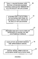
- Figure 1 is a flowchart describing the steps used to intra-operatively present an approximate model of an anatomical structure on an output device.
- the first step is to apply a registration tool to the anatomical surface 20.
- This tool can be a standard digitizing pointer, a laser pointer, or any other registration tool known to a person skilled in the art.
- a position sensing system must be associated to the tool to track the position and orientation of the registration tool as it moves over the surface of the anatomical structure.
- an infrared, light reflecting tracking system having at least three reflectors is used.
- any mechanical, electro-magnetic, or optical position sensing system may be used.
- the next step consists in acquiring input data at each point of contact 22.
- the normal at each point of contact is determined and included in the input data.
- a tool having a small flat surface such as a small disc, is used to acquire the data such that instead of registering only a point, a small surface is registered at each point of contact.
- the input data is then processed into an approximate model of the anatomical surface 23 and is then displayed on the output device 24.
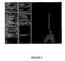
- the processing may simply comprise transforming the input data into a cloud of points forming a mosaic representing a portion of the anatomical structure that was digitized.
- An example of a portion of a femur bone is shown represented by a cloud of points in figure 2.
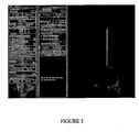
- the input data may be smoothed over to be displayed as a smoothed surface representing a more accurate surface topology of the portion of the anatomical structure that was digitized.
- An example of the same femur bone portion smoothed over can be seen in figure 3. It can be seen from this figure that the normal of each point of contact was taken into consideration when the points were registered. A surface topology is evident from the displayed surface.
- the input data may also be used to reconstruct a three dimensional model of the portion of the anatomical structure that was digitized. This requires a more complex processing of the input data than a simple smoothing over.
- the points registered may be matched to a known model of the same anatomical structure and the model is displayed on the output device with the digitized points indicated on the model. This way, the entire bone can be visualized during the surgery.
- the input data may be used to reconstruct an entire model of the anatomical surface using extrapolation of the input data.
- Another way to display an entire anatomical structure is to attach a portion of a known model to the portion digitized using the registration tool.
- a portion of a known model For example, if the portion of a femur that is digitized consists of the anterior cortex, the condylar surface, and the inter-condylar notch, then a shaft portion and a femoral head from a known model having similar dimensions can be attached to the digitized portion and displayed as an entire femur.
- the known model can be attached to a cloud of points forming a mosaic, a smoothed surface, or a three dimensional reconstruction.
- the model of the anatomical structure displayed on the output device may be adjusted by acquiring more points to better represent the actual topology of the anatomical structure. As more data is acquired, the model displayed is updated to reflect the new information.
- the surface model reconstruction is a process that allows the user to digitize small surfaces instead of points only. These surfaces can be small circles, as can be seen from figure 2.
- the small circle is physically present on the tip of the registration tool as a small, flat disc.
- the size of the disc (radius) is chosen as a compromise between accuracy and time. It is counter-productive to ask a surgeon to take hundreds of points when digitizing the surface of a bone. However, the more points taken, the better the representation of the bone and the more accurate the model.
- the size can also vary depending on the morphology of the bone surface, affecting the precision of the tool. For example, the disc could cover an area of 1cm 2 .
- the disc must be flat on the surface to register as much surface as possible.
- the tool also registers the normal at the point of contact between the flat disc surface and the bone.
- the reconstruction is done in real time.
- Figure 4 is the preferred embodiment of the registration tool to be used in the digitizing process.
- the tool is equipped with a position-sensing device 30, such as those known in the field of tracking, having three position identifying devices.
- both ends of the tool can serve as a digitizing tip, each end having a different radius.
- the smaller end 32 can be used on anatomical surfaces that do not easily accommodate the flat surface of the tool.
- the larger end 34 can be used on flatter anatomical surfaces.
- the user selects on the computer which end is used.
- there can be automatic detection of the end being used such as the computer recognizing the radius of the disc surface when it is placed on the bone surface. For the actual registration of the small surfaces, this can be achieved in several ways.
- the registration tool there can be a button on the tool that controls the digitizing. Alternatively, this can be done by pressing a key on a keyboard to select a point to be digitized. Also alternatively, digitizing can be triggered by a rotating action of the tool by a quarter turn. It can be appreciated that alternative embodiments for the registration tool are possible. For example, other multi-purpose combinations can be made. One end can be an awl, a screwdriver, or a probe, while the other end is a digitizer. Similarly, the tool can be a single-ended digitizer as well.
- Figure 5 shows the system for displaying an approximate model of a surface of an anatomical structure in accordance with the present invention.
- a registration tool 40 sends data to a position sensing system 42 corresponding to its position and orientation relative to an anatomical structure.
- the tool 40 is tracked by the position sensing system 42 in a three-dimensional environment.
- the orientation and position of the tool 40 is captured by the position sensing system and transferred to a storing module 44.
- the data is then sent to an output device 46, such as a monitor, to display to the user.
- FIG. 6 is a block diagram of the storing module 44 in a preferred embodiment.
- a processing module 48 is used to smooth over the mosaic surface formed by the data recorded by the tool 40.
- the initial bone registration procedure is done by collecting information on the surface of the bone.
- the information collected is the position and orientation of the bone surface at each point of contact.
- the normal of the digitized surface is calculated using the mean value of the orientation of the registration tool 40, which is collected by the sensing system 42.
- the processing module 48 receives the orientation and position information and uses a surface-modeling algorithm, such as the marching cubes algorithm, to provide a smoothed over surface of the bone topology. It can be appreciated that any surface-modeling algorithm known in the art can be used to perform the smoothing procedure.
- the points at which the initial data was gathered may also be displayed on top of the smoothed surface.
- the processing module 48 may perform a three-dimensional reconstruction of a bone using the position and orientation data gathered by the registration tool 40.
- This reconstruction is similar to a three dimensional reconstruction of a bone done pre-operatively using other types of data gathering devices such as CT-scans and other scanning devices.
- the three dimensional reconstruction is done independently of any standard or known shape and size of bone.
- a database of known models 50 is available to the processing module 48. In this case, the reconstruction is based on known models.
- the registered points are matched using a best-fit algorithm to a known model of similar size and shape as the anatomical structure under examination.
- the reconstructed shape is then displayed on the output device 46.
- the matched points may be displayed on top of the three dimensional shape.
- the known models are simply used as a reference for the three dimensional reconstruction. The reconstruction algorithm simply uses the known models as a guide in reconstructing a full three dimensional model.
- the known models database 50 comprises a plurality of anatomical structures of varying sizes and shapes.
- the processing module 48 accesses the database 50 and selects a model of similar size and shape to the anatomical structure undergoing operation.
- the database 50 may also comprise portions or parts of complete anatomical structures.
- the database may comprise femoral heads of different sizes and shapes, or femoral shafts of different sizes and shapes.
- These parts of anatomical structures are used to attached any one of three dimensional reconstructions, smoothed over surfaces, or clouds of points forming a portion of an anatomical structure.
- the attached portion provides a more complete visual tool to the surgeon during the surgical procedure. Intra-operative time is saved by limiting the amount of digitizing necessary to have a faithful representation of the areas of interest on the anatomical structure. A better visual tool is provided for guidance during surgical navigation with a computer assisted surgical navigation system.
- the above described system may be used independently, or with a complete computer assisted surgical navigation system.
- a plurality of surgical tools may be tracked and displayed with respect to the intra-operative representation.
- Cutting guides and positioning blocks may be tracked and used in conjunction with the displayed representation.
- the method and system described above may be used on cadavers or dummies in order to test a computer aided surgery system. Testing of new equipment such as a new tracking system, a positioning block, a cutting guide, or so on can also be done in conjunction with the method and system of the present invention.
- the method and system described may also be used on cadavers or dummies as a teaching tool for medical students. Real life situations may be simulated using the system in order to practice various surgical procedures without the risks posed to a patient.
Landscapes
- Health & Medical Sciences (AREA)
- Surgery (AREA)
- Life Sciences & Earth Sciences (AREA)
- Engineering & Computer Science (AREA)
- Heart & Thoracic Surgery (AREA)
- Animal Behavior & Ethology (AREA)
- Veterinary Medicine (AREA)
- Biomedical Technology (AREA)
- Nuclear Medicine, Radiotherapy & Molecular Imaging (AREA)
- Medical Informatics (AREA)
- Molecular Biology (AREA)
- Public Health (AREA)
- General Health & Medical Sciences (AREA)
- Pathology (AREA)
- Oral & Maxillofacial Surgery (AREA)
- Robotics (AREA)
- Processing Or Creating Images (AREA)
- Apparatus For Radiation Diagnosis (AREA)
- Surgical Instruments (AREA)
Applications Claiming Priority (5)
| Application Number | Priority Date | Filing Date | Title |
|---|---|---|---|
| CA0200047 | 2002-01-16 | ||
| WOPCT/CA02/00047 | 2002-01-16 | ||
| US34926702P | 2002-01-18 | 2002-01-18 | |
| US349267P | 2002-01-18 | ||
| PCT/CA2003/000069 WO2003061501A2 (en) | 2002-01-16 | 2003-01-16 | Method and apparatus for reconstructing bone surfaces during surgery |
Publications (2)
| Publication Number | Publication Date |
|---|---|
| EP1465541A2 EP1465541A2 (en) | 2004-10-13 |
| EP1465541B1 true EP1465541B1 (en) | 2007-12-12 |
Family
ID=27614019
Family Applications (1)
| Application Number | Title | Priority Date | Filing Date |
|---|---|---|---|
| EP03700269A Expired - Lifetime EP1465541B1 (en) | 2002-01-16 | 2003-01-16 | Method and apparatus for reconstructing bone surfaces during surgery |
Country Status (8)
| Country | Link |
|---|---|
| EP (1) | EP1465541B1 (es) |
| JP (1) | JP4319043B2 (es) |
| AT (1) | ATE380513T1 (es) |
| AU (1) | AU2003201572A1 (es) |
| CA (1) | CA2473470C (es) |
| DE (1) | DE60318010T2 (es) |
| ES (1) | ES2295547T3 (es) |
| WO (1) | WO2003061501A2 (es) |
Families Citing this family (10)
| Publication number | Priority date | Publication date | Assignee | Title |
|---|---|---|---|---|
| US7274958B2 (en) * | 2002-10-04 | 2007-09-25 | Orthosoft Inc. | Registration pointer with interchangeable tip and method |
| DE502004008977D1 (de) | 2004-10-26 | 2009-03-26 | Brainlab Ag | Präkalibriertes Mehrweginstrument |
| US8211094B2 (en) | 2004-10-26 | 2012-07-03 | Brainlab Ag | Pre-calibrated reusable instrument |
| WO2006079211A1 (en) * | 2005-01-26 | 2006-08-03 | Orthosoft Inc. | Computer-assisted hip joint resurfacing method and system |
| GB2423369A (en) * | 2005-02-22 | 2006-08-23 | Depuy Int Ltd | A position sensing probe for computer assisted surgery |
| WO2006106335A1 (en) * | 2005-04-06 | 2006-10-12 | Depuy International Ltd | Registration system and method |
| US10347380B2 (en) | 2013-03-14 | 2019-07-09 | Think Surgical, Inc. | Intra-operative registration of anatomical structures |
| JP2017535406A (ja) * | 2014-12-01 | 2017-11-30 | ブルー ベルト テクノロジーズ,インク. | 無画像インプラント修正外科手術 |
| US11298186B2 (en) | 2018-08-02 | 2022-04-12 | Point Robotics Medtech Inc. | Surgery assistive system and method for obtaining surface information thereof |
| JP6901160B2 (ja) * | 2019-12-05 | 2021-07-14 | 炳碩生醫股▲フン▼有限公司 | 手術支援システムおよびその表面情報を取得する方法 |
Family Cites Families (12)
| Publication number | Priority date | Publication date | Assignee | Title |
|---|---|---|---|---|
| JPH04183446A (ja) * | 1990-11-19 | 1992-06-30 | Res Dev Corp Of Japan | 画像合成による手術支援システム |
| US6006126A (en) * | 1991-01-28 | 1999-12-21 | Cosman; Eric R. | System and method for stereotactic registration of image scan data |
| FR2699271B1 (fr) * | 1992-12-15 | 1995-03-17 | Univ Joseph Fourier | Procédé de détermination du point d'ancrage fémoral d'un ligament croisé de genou. |
| DE69531994T2 (de) * | 1994-09-15 | 2004-07-22 | OEC Medical Systems, Inc., Boston | System zur positionserfassung mittels einer an einem patientenkopf angebrachten referenzeinheit zur anwendung im medizinischen gebiet |
| US5682886A (en) * | 1995-12-26 | 1997-11-04 | Musculographics Inc | Computer-assisted surgical system |
| US6052611A (en) * | 1997-11-28 | 2000-04-18 | Picker International, Inc. | Frameless stereotactic tomographic scanner for image guided interventional procedures |
| JPH11197159A (ja) * | 1998-01-13 | 1999-07-27 | Hitachi Ltd | 手術支援システム |
| WO1999059106A1 (en) * | 1998-05-13 | 1999-11-18 | Acuscape International, Inc. | Method and apparatus for generating 3d models from medical images |
| CA2333393C (en) * | 1998-05-28 | 2007-08-07 | Orthosoft Inc. | Interactive computer-assisted surgical system and method thereof |
| US6033415A (en) * | 1998-09-14 | 2000-03-07 | Integrated Surgical Systems | System and method for performing image directed robotic orthopaedic procedures without a fiducial reference system |
| JP2003534035A (ja) * | 2000-03-15 | 2003-11-18 | オーソソフト インコーポレイテッド | コンピュータ支援手術器具の自動校正システム |
| FR2816200A1 (fr) * | 2000-11-06 | 2002-05-10 | Praxim | Determination de la position d'une prothese du genou |
-
2003
- 2003-01-16 JP JP2003561447A patent/JP4319043B2/ja not_active Expired - Fee Related
- 2003-01-16 AT AT03700269T patent/ATE380513T1/de not_active IP Right Cessation
- 2003-01-16 AU AU2003201572A patent/AU2003201572A1/en not_active Abandoned
- 2003-01-16 ES ES03700269T patent/ES2295547T3/es not_active Expired - Lifetime
- 2003-01-16 WO PCT/CA2003/000069 patent/WO2003061501A2/en active IP Right Grant
- 2003-01-16 CA CA2473470A patent/CA2473470C/en not_active Expired - Lifetime
- 2003-01-16 DE DE60318010T patent/DE60318010T2/de not_active Expired - Lifetime
- 2003-01-16 EP EP03700269A patent/EP1465541B1/en not_active Expired - Lifetime
Also Published As
| Publication number | Publication date |
|---|---|
| DE60318010D1 (de) | 2008-01-24 |
| ES2295547T3 (es) | 2008-04-16 |
| WO2003061501A3 (en) | 2003-10-16 |
| EP1465541A2 (en) | 2004-10-13 |
| AU2003201572A1 (en) | 2003-09-02 |
| CA2473470C (en) | 2010-09-14 |
| JP2005515017A (ja) | 2005-05-26 |
| DE60318010T2 (de) | 2008-11-27 |
| JP4319043B2 (ja) | 2009-08-26 |
| WO2003061501B1 (en) | 2003-12-04 |
| ATE380513T1 (de) | 2007-12-15 |
| CA2473470A1 (en) | 2003-07-31 |
| WO2003061501A2 (en) | 2003-07-31 |
Similar Documents
| Publication | Publication Date | Title |
|---|---|---|
| US7715602B2 (en) | Method and apparatus for reconstructing bone surfaces during surgery | |
| US7643862B2 (en) | Virtual mouse for use in surgical navigation | |
| JP6879927B2 (ja) | 外科的処置を計画及び実行するシステム | |
| US8257360B2 (en) | Determining femoral cuts in knee surgery | |
| US8934961B2 (en) | Trackable diagnostic scope apparatus and methods of use | |
| EP0501993B1 (en) | Probe-correlated viewing of anatomical image data | |
| US6690960B2 (en) | Video-based surgical targeting system | |
| US8165659B2 (en) | Modeling method and apparatus for use in surgical navigation | |
| US20070038059A1 (en) | Implant and instrument morphing | |
| JP5328137B2 (ja) | 用具又は埋植物の表現を表示するユーザ・インタフェイス・システム | |
| US7427272B2 (en) | Method for locating the mechanical axis of a femur | |
| US8682413B2 (en) | Systems and methods for automated tracker-driven image selection | |
| US8774900B2 (en) | Computer-aided osteoplasty surgery system | |
| US7815644B2 (en) | Instrumentation and methods for refining image-guided and navigation-based surgical procedures | |
| US20070073133A1 (en) | Virtual mouse for use in surgical navigation | |
| US20070233156A1 (en) | Surgical instrument | |
| JP2020511239A (ja) | ナビゲーション手術における拡張現実ディスプレイのためのシステム及び方法 | |
| US20070016009A1 (en) | Image guided tracking array and method | |
| JP2016512973A (ja) | 身体に対して対象を追跡するための追跡装置 | |
| US20080154120A1 (en) | Systems and methods for intraoperative measurements on navigated placements of implants | |
| EP1465541B1 (en) | Method and apparatus for reconstructing bone surfaces during surgery | |
| US20080119724A1 (en) | Systems and methods for intraoperative implant placement analysis | |
| Vannier | Evaluation of 3D imaging | |
| CN214157490U (zh) | 一种应用三维医学影像与患者实时重合方法的手术辅助系统 | |
| CA2482851A1 (en) | Determining femoral cuts in knee surgery |
Legal Events
| Date | Code | Title | Description |
|---|---|---|---|
| PUAI | Public reference made under article 153(3) epc to a published international application that has entered the european phase |
Free format text: ORIGINAL CODE: 0009012 |
|
| 17P | Request for examination filed |
Effective date: 20040804 |
|
| AK | Designated contracting states |
Kind code of ref document: A2 Designated state(s): AT BE BG CH CY CZ DE DK EE ES FI FR GB GR HU IE IT LI LU MC NL PT SE SI SK TR |
|
| AX | Request for extension of the european patent |
Extension state: AL LT LV MK RO |
|
| RIN1 | Information on inventor provided before grant (corrected) |
Inventor name: RICHARD, ALAIN |
|
| 17Q | First examination report despatched |
Effective date: 20061017 |
|
| 17Q | First examination report despatched |
Effective date: 20061017 |
|
| GRAP | Despatch of communication of intention to grant a patent |
Free format text: ORIGINAL CODE: EPIDOSNIGR1 |
|
| GRAS | Grant fee paid |
Free format text: ORIGINAL CODE: EPIDOSNIGR3 |
|
| GRAA | (expected) grant |
Free format text: ORIGINAL CODE: 0009210 |
|
| AK | Designated contracting states |
Kind code of ref document: B1 Designated state(s): AT BE BG CH CY CZ DE DK EE ES FI FR GB GR HU IE IT LI LU MC NL PT SE SI SK TR |
|
| REG | Reference to a national code |
Ref country code: GB Ref legal event code: FG4D |
|
| REG | Reference to a national code |
Ref country code: CH Ref legal event code: EP |
|
| REG | Reference to a national code |
Ref country code: IE Ref legal event code: FG4D |
|
| REF | Corresponds to: |
Ref document number: 60318010 Country of ref document: DE Date of ref document: 20080124 Kind code of ref document: P |
|
| REG | Reference to a national code |
Ref country code: CH Ref legal event code: NV Representative=s name: SCHMAUDER & PARTNER AG PATENTANWALTSBUERO |
|
| REG | Reference to a national code |
Ref country code: ES Ref legal event code: FG2A Ref document number: 2295547 Country of ref document: ES Kind code of ref document: T3 |
|
| PG25 | Lapsed in a contracting state [announced via postgrant information from national office to epo] |
Ref country code: SE Free format text: LAPSE BECAUSE OF FAILURE TO SUBMIT A TRANSLATION OF THE DESCRIPTION OR TO PAY THE FEE WITHIN THE PRESCRIBED TIME-LIMIT Effective date: 20080312 |
|
| PG25 | Lapsed in a contracting state [announced via postgrant information from national office to epo] |
Ref country code: NL Free format text: LAPSE BECAUSE OF FAILURE TO SUBMIT A TRANSLATION OF THE DESCRIPTION OR TO PAY THE FEE WITHIN THE PRESCRIBED TIME-LIMIT Effective date: 20071212 Ref country code: FI Free format text: LAPSE BECAUSE OF FAILURE TO SUBMIT A TRANSLATION OF THE DESCRIPTION OR TO PAY THE FEE WITHIN THE PRESCRIBED TIME-LIMIT Effective date: 20071212 Ref country code: SI Free format text: LAPSE BECAUSE OF FAILURE TO SUBMIT A TRANSLATION OF THE DESCRIPTION OR TO PAY THE FEE WITHIN THE PRESCRIBED TIME-LIMIT Effective date: 20071212 |
|
| NLV1 | Nl: lapsed or annulled due to failure to fulfill the requirements of art. 29p and 29m of the patents act | ||
| PG25 | Lapsed in a contracting state [announced via postgrant information from national office to epo] |
Ref country code: CZ Free format text: LAPSE BECAUSE OF FAILURE TO SUBMIT A TRANSLATION OF THE DESCRIPTION OR TO PAY THE FEE WITHIN THE PRESCRIBED TIME-LIMIT Effective date: 20071212 |
|
| ET | Fr: translation filed | ||
| PG25 | Lapsed in a contracting state [announced via postgrant information from national office to epo] |
Ref country code: MC Free format text: LAPSE BECAUSE OF NON-PAYMENT OF DUE FEES Effective date: 20080131 Ref country code: BE Free format text: LAPSE BECAUSE OF FAILURE TO SUBMIT A TRANSLATION OF THE DESCRIPTION OR TO PAY THE FEE WITHIN THE PRESCRIBED TIME-LIMIT Effective date: 20071212 Ref country code: SK Free format text: LAPSE BECAUSE OF FAILURE TO SUBMIT A TRANSLATION OF THE DESCRIPTION OR TO PAY THE FEE WITHIN THE PRESCRIBED TIME-LIMIT Effective date: 20071212 |
|
| PG25 | Lapsed in a contracting state [announced via postgrant information from national office to epo] |
Ref country code: PT Free format text: LAPSE BECAUSE OF FAILURE TO SUBMIT A TRANSLATION OF THE DESCRIPTION OR TO PAY THE FEE WITHIN THE PRESCRIBED TIME-LIMIT Effective date: 20080512 |
|
| PLBE | No opposition filed within time limit |
Free format text: ORIGINAL CODE: 0009261 |
|
| STAA | Information on the status of an ep patent application or granted ep patent |
Free format text: STATUS: NO OPPOSITION FILED WITHIN TIME LIMIT |
|
| PG25 | Lapsed in a contracting state [announced via postgrant information from national office to epo] |
Ref country code: DK Free format text: LAPSE BECAUSE OF FAILURE TO SUBMIT A TRANSLATION OF THE DESCRIPTION OR TO PAY THE FEE WITHIN THE PRESCRIBED TIME-LIMIT Effective date: 20071212 |
|
| 26N | No opposition filed |
Effective date: 20080915 |
|
| PG25 | Lapsed in a contracting state [announced via postgrant information from national office to epo] |
Ref country code: EE Free format text: LAPSE BECAUSE OF FAILURE TO SUBMIT A TRANSLATION OF THE DESCRIPTION OR TO PAY THE FEE WITHIN THE PRESCRIBED TIME-LIMIT Effective date: 20071212 Ref country code: GR Free format text: LAPSE BECAUSE OF FAILURE TO SUBMIT A TRANSLATION OF THE DESCRIPTION OR TO PAY THE FEE WITHIN THE PRESCRIBED TIME-LIMIT Effective date: 20080313 |
|
| PG25 | Lapsed in a contracting state [announced via postgrant information from national office to epo] |
Ref country code: BG Free format text: LAPSE BECAUSE OF FAILURE TO SUBMIT A TRANSLATION OF THE DESCRIPTION OR TO PAY THE FEE WITHIN THE PRESCRIBED TIME-LIMIT Effective date: 20080312 |
|
| PG25 | Lapsed in a contracting state [announced via postgrant information from national office to epo] |
Ref country code: CY Free format text: LAPSE BECAUSE OF FAILURE TO SUBMIT A TRANSLATION OF THE DESCRIPTION OR TO PAY THE FEE WITHIN THE PRESCRIBED TIME-LIMIT Effective date: 20071212 |
|
| REG | Reference to a national code |
Ref country code: CH Ref legal event code: PCAR Free format text: SCHMAUDER & PARTNER AG PATENT- UND MARKENANWAELTE VSP;ZWAENGIWEG 7;8038 ZUERICH (CH) |
|
| PGFP | Annual fee paid to national office [announced via postgrant information from national office to epo] |
Ref country code: ES Payment date: 20100126 Year of fee payment: 8 Ref country code: IE Payment date: 20100114 Year of fee payment: 8 |
|
| PGFP | Annual fee paid to national office [announced via postgrant information from national office to epo] |
Ref country code: AT Payment date: 20091211 Year of fee payment: 8 |
|
| PG25 | Lapsed in a contracting state [announced via postgrant information from national office to epo] |
Ref country code: LU Free format text: LAPSE BECAUSE OF NON-PAYMENT OF DUE FEES Effective date: 20080116 Ref country code: HU Free format text: LAPSE BECAUSE OF FAILURE TO SUBMIT A TRANSLATION OF THE DESCRIPTION OR TO PAY THE FEE WITHIN THE PRESCRIBED TIME-LIMIT Effective date: 20080613 |
|
| PG25 | Lapsed in a contracting state [announced via postgrant information from national office to epo] |
Ref country code: TR Free format text: LAPSE BECAUSE OF FAILURE TO SUBMIT A TRANSLATION OF THE DESCRIPTION OR TO PAY THE FEE WITHIN THE PRESCRIBED TIME-LIMIT Effective date: 20071212 |
|
| PGFP | Annual fee paid to national office [announced via postgrant information from national office to epo] |
Ref country code: FR Payment date: 20101221 Year of fee payment: 9 |
|
| PGFP | Annual fee paid to national office [announced via postgrant information from national office to epo] |
Ref country code: IT Payment date: 20110126 Year of fee payment: 9 |
|
| REG | Reference to a national code |
Ref country code: IE Ref legal event code: MM4A |
|
| PG25 | Lapsed in a contracting state [announced via postgrant information from national office to epo] |
Ref country code: AT Free format text: LAPSE BECAUSE OF NON-PAYMENT OF DUE FEES Effective date: 20110116 |
|
| PG25 | Lapsed in a contracting state [announced via postgrant information from national office to epo] |
Ref country code: IE Free format text: LAPSE BECAUSE OF NON-PAYMENT OF DUE FEES Effective date: 20110117 |
|
| REG | Reference to a national code |
Ref country code: ES Ref legal event code: FD2A Effective date: 20120220 |
|
| PG25 | Lapsed in a contracting state [announced via postgrant information from national office to epo] |
Ref country code: ES Free format text: LAPSE BECAUSE OF NON-PAYMENT OF DUE FEES Effective date: 20110117 |
|
| REG | Reference to a national code |
Ref country code: FR Ref legal event code: ST Effective date: 20120928 |
|
| PG25 | Lapsed in a contracting state [announced via postgrant information from national office to epo] |
Ref country code: IT Free format text: LAPSE BECAUSE OF NON-PAYMENT OF DUE FEES Effective date: 20120116 |
|
| PG25 | Lapsed in a contracting state [announced via postgrant information from national office to epo] |
Ref country code: FR Free format text: LAPSE BECAUSE OF NON-PAYMENT OF DUE FEES Effective date: 20120131 |
|
| REG | Reference to a national code |
Ref country code: CH Ref legal event code: PFA Owner name: ORTHOSOFT ULC, CA Free format text: FORMER OWNER: ORTHOSOFT INC., CA |
|
| REG | Reference to a national code |
Ref country code: DE Ref legal event code: R082 Ref document number: 60318010 Country of ref document: DE Representative=s name: BETTEN & RESCH PATENT- UND RECHTSANWAELTE PART, DE Ref country code: DE Ref legal event code: R081 Ref document number: 60318010 Country of ref document: DE Owner name: ORTHOSOFT ULC, CA Free format text: FORMER OWNER: ORTHOSOFT, INC., MONTREAL, QUEBEC, CA |
|
| PGFP | Annual fee paid to national office [announced via postgrant information from national office to epo] |
Ref country code: GB Payment date: 20211214 Year of fee payment: 20 |
|
| PGFP | Annual fee paid to national office [announced via postgrant information from national office to epo] |
Ref country code: CH Payment date: 20211210 Year of fee payment: 20 |
|
| PGFP | Annual fee paid to national office [announced via postgrant information from national office to epo] |
Ref country code: DE Payment date: 20211215 Year of fee payment: 20 |
|
| REG | Reference to a national code |
Ref country code: DE Ref legal event code: R071 Ref document number: 60318010 Country of ref document: DE |
|
| REG | Reference to a national code |
Ref country code: CH Ref legal event code: PL |
|
| REG | Reference to a national code |
Ref country code: GB Ref legal event code: PE20 Expiry date: 20230115 |
|
| PG25 | Lapsed in a contracting state [announced via postgrant information from national office to epo] |
Ref country code: GB Free format text: LAPSE BECAUSE OF EXPIRATION OF PROTECTION Effective date: 20230115 |