EP1465217A1 - Process and apparatus for demagnetising objects - Google Patents
Process and apparatus for demagnetising objects Download PDFInfo
- Publication number
- EP1465217A1 EP1465217A1 EP03405222A EP03405222A EP1465217A1 EP 1465217 A1 EP1465217 A1 EP 1465217A1 EP 03405222 A EP03405222 A EP 03405222A EP 03405222 A EP03405222 A EP 03405222A EP 1465217 A1 EP1465217 A1 EP 1465217A1
- Authority
- EP
- European Patent Office
- Prior art keywords
- coils
- alternating field
- series resonant
- resonant circuit
- objects
- Prior art date
- Legal status (The legal status is an assumption and is not a legal conclusion. Google has not performed a legal analysis and makes no representation as to the accuracy of the status listed.)
- Withdrawn
Links
Images
Classifications
-
- H—ELECTRICITY
- H01—ELECTRIC ELEMENTS
- H01F—MAGNETS; INDUCTANCES; TRANSFORMERS; SELECTION OF MATERIALS FOR THEIR MAGNETIC PROPERTIES
- H01F13/00—Apparatus or processes for magnetising or demagnetising
- H01F13/006—Methods and devices for demagnetising of magnetic bodies, e.g. workpieces, sheet material
Definitions
- the invention relates to a method and a device for demagnetizing Objects according to the preambles of the independent claims.
- a known method for demagnetizing objects uses an open one Magnetic circuit with a coil through which a constant alternating current flows.
- the magnetic core is placed on the object and the alternating current is switched on.
- the magnetic core is then slowly pulled away from the object by hand.
- a Device for this method are limited in size and weight of the magnetic core Demagnetization is strongly influenced by environmental conditions and is not precise reproducible. Demagnetization is incomplete and not always equally good.
- a coil tunnel is used worked with large electromagnets through which alternating current flows.
- the Object is pulled through the coil tunnel with a stationary magnetic field.
- the demagnetizing effect is limited.
- the effect improved by mechanically rotating the electromagnets.
- the object of the invention is to provide a method with which objects so far can be demagnetized so that there is no longer any measurable residual magnetism.
- Another object of the invention is to provide a device with which correspond to the process objects can be demagnetized.
- the method is suitable for all types of ferromagnetic Parts such as stamped parts, turned parts, springs, pipes, etc.
- the entire system in this Case the ferromagnetic objects as a whole are completely demagnetized.
- the ferromagnetic objects by an alternating magnetic field is pulled through, they remain locally in the magnetic field for a certain time within a station.
- the change of the alternating field in this station controlled by the coils electronically in terms of frequency and amplitude electronically to be controlled.
- the alternating field is brought to zero at the station, whereupon the ferromagnetic objects come out the station. They are now demagnetized to the extent that none Residual magnetism is more measurable.
- the demagnetization process takes place in cycles instead of.
- the frames and attachments of shadow masks on screens represent a special case for which the procedure follows pre-treatment.
- At the Processes with pretreatment are first magnetically hard spots, such as weld seams, Air gaps and so on in the workpiece to be treated locally locally with high fields by means of a rod choke coil, a coil with a rod-shaped laminated iron core, in Alternating field pre-treated. This makes these magnetically hard spots at least partially demagnetized.
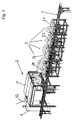
- the device according to FIG. 1 shows an embodiment which is based on these basic ideas is working.
- the demagnetization device comprises a transport route 1 on which the objects to be demagnetized are transported to, away and further.
- the Transport route leads through the demagnetization station 3.
- Transportstrasse 1 leads under one or several pretreatment stations 2 and then to Demagnetization station 3.
- Each pretreatment station 2 comprises a rod choke coil 21-24 in and of itself known type.
- the demagnetization station 3 comprises two opposite one another Boxes 31, 32, each comprising a coil.
- the two boxes with each other spaced coils form a zone in which a homogeneous field is generated.
- the Both coils are part of a series resonant circuit, which is created using an inverter is current controlled. They have no core.
- the two coils in boxes 31, 32 are are arranged opposite each other on both sides of a conveyor belt.
- the objects are now in time on the transport line from the pre-treatment station 2 to pretreatment station 2 and finally through demagnetization station 3 transported.
- the item remains in each station for a certain period of time.
- the magnetically hard spots are caused by strong fields pretreated so that they can no longer be identified as such and the magnetic properties are reasonably balanced.
- the cycle times are the problem or the treatment times in the individual Stations adjusted
- the longest treatment time in one of the stations is the Clock rate. Automation is possible
- the penetration depth of the magnetic strength is the same with the same amplitude of the alternating field the object depends on the frequency of the alternating field. This is also the Given the time of stay.
- a material is suitable for 1mm thick Frequency of the alternating field of about 200 Hz, which means a pulse time of at least 0.5 Seconds. With increasing penetration depth or material thickness the frequency decreases. For an object with a material thickness of 10mm, this corresponds to required frequency of the alternating field about 10 Hz.
- the residence time of the object in the alternating field must be at least one Correspond to a time span of the order of 100 periods or alternating pulses.
- the object In During this time of stay, the object must remain within the alternating field. So it will an influencing time of at least 10 seconds is required. Preferably during this influence time the transport stopped, so that the object is stationary in the Alternating field remains.
- the demagnetization frequency is a Compromise between the production speed, with the highest possible frequency, and the depth of penetration, which requires a lower frequency. From these specifications, the Resonance frequency of the entire resonant circuit is set. Everyone Demagnetization begins at this resonance frequency. At this starting point the object affects the resonance frequency negligibly, since the system in the Range of magnetic saturation is operated.
- the station includes two Boxes, one on each side of the item.
- they are two coils of the series resonant circuit to form a single long air coil summarized. The area with the alternating field is then located lengthways inside inside the long air coil.
- the series resonant circuit is now controlled by a power source. This happens with one Current regulator or an inverter. The effect of the magnetic field is independent of the Temperature in the coil kept constant. This leaves the field created without unwanted temperature influence precisely.
- the current regulator comes with a Provide zero point correction. The zero point correction symmetrizes the by the Series resonant circuit flowing current, so that no DC voltage element arises. So is at the time the item is removed from the station, none Tension and no more charge present.
- the two each other opposite coils are preferably polarized equally in terms of magnetic field.
- the internal Programming, or the ramp function of the inverter used for control. You start the inverter and thus the series resonant circuit at the resonance frequency. Then let the inverter series resonant circuit system shut down. The one through the internal Programming frequency and voltage reduction in the inverter is done in one Ratio of about 1:20. This results in the current reduction in the series resonant circuit in the Range from 1.1000 to 1: 5000.
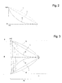
- the demagnetization curve thus corresponds approximately to that Exponential curve E of Figure 2
- the alternating field is, according to those described above Principles, during a period of expiration of between 20 and 500 periods or alternating pulses from the resonance frequency at time T0 to zero at time T ( Figure 3) dismantled. scaled back. Experiments were conducted with a length of stay between 50 and 250 periods always achieved very good results in demagnetization.
- the alternating field is also used during a period of time the expiry of between 20 and 500 periods or alternating pulses from the Resonance frequency at time T0 reduced to zero at time T ( Figure 3) resp scaled back.
- the optimal length of stay is approximately 100 Periods.
- the vibration in the series resonant circuit is controlled by a current controller controlled by current.
- FIG. 2 shows examples of demagnetization curves as are now possible using this clocked method.
- the series resonant circuit brings a usual exponential curve E by decaying vibrations. You can now determine the time period in which the residual magnetism in the object can be brought down to values that are no longer measurable. During this period, the object remains in the area between the two adjacent coils of the series resonant circuit.
- a separate current control is used.
- the start of the The process starts at the resonance frequency at maximum current Swing out series oscillating circuit damping during the required decay time At.
- the Control of the series resonant circuit is an inverter external current control of the Inverters with rectangular pulses are used.
- the demagnetization curve influenced by using individual or each of the vibrations at the beginning of the climb through additional supply of the series resonant circuit by means of rectangular pulses. Therefore the separate current control of the inverter is suitable. This allows the damping of the Vibrations and thus the demagnetization process according to the problem to get voted.
- the duration of the process is given by the principles mentioned above.
- the object After the controlled oscillation of the series resonant circuit, the object is removed taken from the station. It is no longer a voltage, a charge, or a magnetic field available. This is an extraordinary advantage for the demagnetizing device.
- the transport of the objects through the conveyor belt takes place in a clocked manner at the start-stop or fast - slow operation. This is during the stop - or slow phase Workpiece within the alternating field.
- After swinging out of the series resonant circuit there is no more voltage. There is no more electricity and there are no more charges available. There is also no risk of electric shock for Operators So when the device is finally turned off, too no residual loads left. This makes repairs and maintenance, e.g. at the Conveyor belt, completely harmless.
Landscapes
- Engineering & Computer Science (AREA)
- Power Engineering (AREA)
- General Induction Heating (AREA)
Abstract
Description
Die Erfindung betrifft ein Verfahren und eine Vorrichtung zum Entmagnetisieren von Gegenständen nach den Oberbegriffen der unabhängigen Ansprüche.The invention relates to a method and a device for demagnetizing Objects according to the preambles of the independent claims.
Ein bekanntes Verfahren zum Entmagnetisieren von Gegenständen benützt einen offenen Magnetkreis mit einer Spule, welche von einem konstanten Wechselstrom durchflossen wird. Der Magnetkern wird auf den Gegenstand aufgelegt und der Wechselstrom eingeschaltet. Darauf wird der Magnetkern langsam von Hand vom Gegenstand weggezogen. Bei einer Vorrichtung für dieses Verfahren sind Grösse und Gewicht des Magnetkerns begrenzt Der Entmagnetisiervorgang ist stark durch Umgebungsbedingungen beeinflusst und nicht präzise reproduzierbar. Die Entmagnetisierung ist unvollständig und nicht immer gleich gut.A known method for demagnetizing objects uses an open one Magnetic circuit with a coil through which a constant alternating current flows. The magnetic core is placed on the object and the alternating current is switched on. The magnetic core is then slowly pulled away from the object by hand. At a Device for this method are limited in size and weight of the magnetic core Demagnetization is strongly influenced by environmental conditions and is not precise reproducible. Demagnetization is incomplete and not always equally good.
Ein solches Verfahren ist in DE 30 05 927 A1 (Steingroever) beschrieben. Dabei wird die Frequenz der Speisespannung der Spule langsam an die Resonanzfrequenz des zugehrenden Schwingkreises herangefahren, worauf die Spannung reduziert wird und damit die Amplitude des auf die zu entmagnetisierenden Teile wirkenden Wechselfeldes reduziert. Ein Nachteil dieser Methode besteht darin, dass für die Annäherung an die Resonanzfrequenz viel Zeit benötigt wird. Der Zeitbedarf ist so gross, dass eine effizientes Entmagnetisieren von Objekten in einem Durchlaufverfahren nicht möglich ist.Such a method is described in DE 30 05 927 A1 (Steingroever). The Frequency of the supply voltage of the coil slowly to the resonance frequency of the the associated resonant circuit, whereupon the voltage is reduced and thus reduces the amplitude of the alternating field acting on the parts to be demagnetized. A disadvantage of this method is that for approaching the Resonance frequency takes a lot of time. The time requirement is so great that an efficient one Demagnetizing objects in a continuous process is not possible.
Bei einem weitern bekannten Verfahren nach DE 3718936 A1 wird mit einem Spulentunnel mit grossen, von Wechselstrom durchflossenen, Elektromagneten gearbeitet. Der Gegenstand wird durch den Spulentunnel mit stationärem Magnetfeld hindurchgezogen. Dadurch ist der Gegenstand dem Magnetfeld zuerst zunehmend, dann abnehmend ausgesetzt. Die entmagnetisierende Wirkung ist beschränkt. Hier wird die Wirkung verbessert, indem die Elektromagnete mechanisch rotieren. In a further known method according to DE 3718936 A1, a coil tunnel is used worked with large electromagnets through which alternating current flows. The Object is pulled through the coil tunnel with a stationary magnetic field. As a result, the object is first increasing in the magnetic field, then decreasing exposed. The demagnetizing effect is limited. Here's the effect improved by mechanically rotating the electromagnets.
Bei der heutigen Verwendung von Materialen für mechanische Komponenten und der breiten Verwendung von empfindlichen elektronischen Komponenten und Schaltungen wird der Restmagnetismus in Gegenständen zu einem immer wichtigeren Problem. Der in Gegenständen vorhandene Restmagnetismus wird zu einem zentralen Qualitätskriterium für Zulieferer. Durch höhere Technologie und Materialauswahl kann insbesondere bei der Massenteilefertigung der Kostenfaktor reduziert werden. Allerdings handelt man sich dafür andere Störfaktoren, wie eben Restmagnetismus, ein.With today's use of materials for mechanical components and the broad The use of sensitive electronic components and circuits Residual magnetism in objects to an increasingly important problem. The in Objects existing residual magnetism becomes a central quality criterion for Suppliers. Due to higher technology and choice of materials, the Mass production the cost factor can be reduced. However, it is for that other disruptive factors, such as residual magnetism.
Aufgabe der Erfindung ist es, ein Verfahren anzugeben, mit welchem Gegenstände soweit entmagnetisiert werden können, dass kein messbarer Restmagnetismus mehr vorhanden ist.The object of the invention is to provide a method with which objects so far can be demagnetized so that there is no longer any measurable residual magnetism.
Eine weitere Aufgabe der Erfindung besteht darin, eine Vorrichtung anzugeben, mit welcher entsprechen dem Verfahren Gegenstände entmagnetisiert werden können.Another object of the invention is to provide a device with which correspond to the process objects can be demagnetized.
Diese Aufgabe wird durch die Erfindung gemäss den Oberbegriffen der unabhängigen Patentansprüche gelöst.This object is achieved by the invention according to the preambles of the independent Claims resolved.
Die Erfindung wird nachstehend im Zusammenhang mit den Zeichnungen beschrieben. Es zeigen:
- Figur 1
- Vorrichtung in Ansicht
Figur 2- Entmagnetisierungskurven
und - Figur 3
- Stützen der Schwingungen
- Figure 1
- Device in view
- Figure 2
- demagnetization
and - Figure 3
- Support the vibrations
Nachfolgend wird kurz auf die Grundlagen und Grundgedanken der erfindungsgemässen Verfahrens eingegangen. Das Verfahren eignet sich für all Arten von ferromagnetischen Teilen, wie beispielsweise Stanzteile, Drehteile, Federn, Rohre usw.The following is briefly the basics and basic ideas of the inventive Process received. The method is suitable for all types of ferromagnetic Parts such as stamped parts, turned parts, springs, pipes, etc.
In einem nun erfindungsgemäss entscheidenden Schritt wird das ganze System, in diesem Falle die ferromagnetische Objekte als Ganzes komplett entmagnetisiert. Statt dass, gemäss Stand der Technik, die ferromagnetische Objekte durch ein magnetisches Wechselfeld durchgezogen wird, verbleiben sie während einer gewissen Zeit örtlich im Magnetfeld innerhalb einer Station. Nun wird die Aenderung des Wechselfeldes in dieser Station gesteuert, indem die Spulen elektronisch in Bezug auf Frequenz und Amplitude elektronisch gesteuert werden. Während einer gewissen Aufenthaltszeit der ferromagnetische Objekte in der Station wird das Wechselfeld auf Null gebracht, worauf die ferromagnetische Objekte aus der Station entfernt werden. Sie sind nun soweit entmagnetisiert, dass kein Restmagnetismus mehr messbar ist. Der Ablauf der Entmagnetisierung findet also taktweise statt.In a step which is now decisive according to the invention, the entire system, in this Case the ferromagnetic objects as a whole are completely demagnetized. Instead of that, according to State of the art, the ferromagnetic objects by an alternating magnetic field is pulled through, they remain locally in the magnetic field for a certain time within a station. Now the change of the alternating field in this station controlled by the coils electronically in terms of frequency and amplitude electronically to be controlled. During a certain period of stay of the ferromagnetic objects in The alternating field is brought to zero at the station, whereupon the ferromagnetic objects come out the station. They are now demagnetized to the extent that none Residual magnetism is more measurable. The demagnetization process takes place in cycles instead of.
Ein besonderer Fall stellen die Rahmen und Anbauten von Lochmasken von Bildschirmen dar, für welche das Verfahren im Anschluss an eine Vorbehandlung anschliesst. Beim Verfahren mit Vorbehandlung werden zuerst magnetisch harte Stellen, wie Schweissnähte, Luftspalte und so weiter im zu behandelnden Werkstück örtlich lokal mit hohen Feldern mittels einer Stabdrosselspule, einer Spule mit stabförmig lammelliertem Eisenkern, im Wechselfeld vorbehandelt. Diese magnetisch harten Stellen werden dadurch mindestens teilweise entmagnetisiert.The frames and attachments of shadow masks on screens represent a special case for which the procedure follows pre-treatment. At the Processes with pretreatment are first magnetically hard spots, such as weld seams, Air gaps and so on in the workpiece to be treated locally locally with high fields by means of a rod choke coil, a coil with a rod-shaped laminated iron core, in Alternating field pre-treated. This makes these magnetically hard spots at least partially demagnetized.
Die Vorrichtung nach Figur 1 zeigt eine Ausführung, welche nach diesen Grundgedanken
arbeitet. Die Entmagnetisierungsvorrichtung umfasst eine Transportstrasse 1, auf welche
die zu entmagnetisierenden Gegenstände zu-, weg- und weitertransportiert werden. Die
Transportstrasse führt durch die Entmagnetisierungsstation 3 hindurch. Im speziellen Fall,
bei dem auch eine Vorbehandlung durchgeführt wird, führt die Transportstrasse 1 unter einer
oder mehreren Vorbehandlungsstationen 2 vorbei und anschliessend zur
Entmagnetisierungsstation 3.The device according to FIG. 1 shows an embodiment which is based on these basic ideas
is working. The demagnetization device comprises a transport route 1 on which
the objects to be demagnetized are transported to, away and further. The
Transport route leads through the demagnetization station 3. In the special case,
in which pretreatment is also carried out, Transportstrasse 1 leads under one
or
Jede Vorbehandlungsstation 2 umfasst eine Stabdrosselspule 21- 24 an und für sich
bekannter Art. Die Entmagnetisierungsstation 3 umfasst zwei einander gegenüberliegende
Boxen 31, 32, welche je eine Spule umfassen. Die beiden Boxen mit den voneinander
beabstandeten Spulen bilden eine Zone in der eine homogenes Feld erzeugt wird. Die
beiden Spulen sind Teil eines Serieschwingkreises, welcher mittels einem Inverter
stromgesteuert ist. Sie weisen keinen Kern auf. Die beiden Spulen in den Boxen 31, 32 sind
einander gegenüberliegend beiderseits eines Transportbandes angeordnet sind.Each
Die Gegenstände werden nun im Takt auf der Transportstrasse von Vorbehandlungsstation
2 zu Vorbehandlungsstation 2 und schliesslich durch die Entmagnetisierungsstation 3
transportiert. In jeder Station verbleibt der Gegenstand während einer gewissen Zeitspanne.
In den Vorbehandlungsstationen werden die magnetisch harten Stellen durch starke Felder
vorbehandelt, so dass sie nicht mehr als solche festgestellt werden können und die
magnetischen Eigenschaften einigermassen ausgeglichen sind. The objects are now in time on the transport line from the
Die Taktzeiten werden dem Problem respektive den Behandlungszeiten in der einzelnen Stationen angepasst Dabei gibt die längste Behandlungszeit in einer der Stationen die Taktrate vor. Eine Automatisierung ist möglichThe cycle times are the problem or the treatment times in the individual Stations adjusted The longest treatment time in one of the stations is the Clock rate. Automation is possible
In der eigentlichen und massgebenden Entmagnetisierungsstation 3 werden die magnetischen Eigenschaften der Objekte auf nicht mehr messbare Werte reduziert. Auch in dieser Station verbleiben die Gegenstände während der dazu benötigten Beeinflussungszeit ortsfest.In the actual and authoritative demagnetization station 3, the Magnetic properties of the objects reduced to values that can no longer be measured. Also in The objects remain in this station during the influencing time required for this stationary.
Es handelt sich also um ein getaktetes Durchlaufverfahren. Der Transport der Gegenstände
durch das Transportband erfolgt somit getaktet im start-stop oder schnell - langsam Betrieb.
Für dieses getaktete Durchlaufverfahren mit dem Transport und dem Betrieb der
Vorbehandlungsstationen 2 wird eine Steuerung bekannter Art verwendet.So it is a clocked continuous process. The transportation of the objects
through the conveyor belt there is a clocked start-stop or fast - slow operation.
For this clocked continuous process with the transport and operation of the
Für die Ansteuerung der Entmagnetisierungsstation 3 werden alternativ zwei Varianten von Ansteuerungen benützt.For the control of the demagnetization station 3, two variants of are alternatively Controls used.
Erstens ist die Eindringtiefe der Magnetstärke bei gleicher Amplitude des Wechselfeldes in den Gegenstand von der Frequenz des Wechselfeldes abhängig. Dadurch ist auch die Aufenthaltszeit gegeben. Für Material von 1mm Stärke eignet sich beispielsweise eine Frequenz des Wechselfeldes von etwa 200 Hz, was einer Pulszeit von mindestens 0,5 Sekunden entspricht. Mit zunehmender benötigter Eindringtiefe respektive Materialdicke nimmt die Frequenz ab. Für einen Gegenstand mit 10mm Materialdicke entspricht die benötigte Frequenz des Wechselfeldes etwa 10 Hz .First, the penetration depth of the magnetic strength is the same with the same amplitude of the alternating field the object depends on the frequency of the alternating field. This is also the Given the time of stay. For example, a material is suitable for 1mm thick Frequency of the alternating field of about 200 Hz, which means a pulse time of at least 0.5 Seconds. With increasing penetration depth or material thickness the frequency decreases. For an object with a material thickness of 10mm, this corresponds to required frequency of the alternating field about 10 Hz.
Zweitens muss die Aufenthaltszeit des Objektes im Wechselfeld mindestens einer Zeitspanne in der Grössenordnung von 100 Perioden oder Wechselpulsen entsprechen. In dieser Aufenthaltszeit muss das Objekt innerhalb dem Wechselfeld bleiben. Es wird also eine Beeinflussungszeit von mindestens 10 Sekunden benötigt. Vorzugsweise wird während dieser Beeinflussungszeit der Transport gestoppt, so dass das Objekt ortsfest im Wechselfeld bleibt.Second, the residence time of the object in the alternating field must be at least one Correspond to a time span of the order of 100 periods or alternating pulses. In During this time of stay, the object must remain within the alternating field. So it will an influencing time of at least 10 seconds is required. Preferably during this influence time the transport stopped, so that the object is stationary in the Alternating field remains.
Um eine schnelle Taktrate für den Durchlauf der Entmagnetisierungen zu erhalten wird nun die Frequenz des Wechselfeldes optimiert. Die Entmagnetisierungsfrequenz ist ein Kompromiss zwischen der Produktionsgeschwindigkeit, mit möglichst hoher Frequenz, und der Eindringtiefe, welche eine niedere Frequenz verlangt. Aus diesen Vorgaben wird die Resonanzfrequenz des gesamten Schwingkreises festgelegt. Jeder Entmagnetisierungsvorgang beginnt auf dieser Resonanzfrequenz. An diesem Startpunkt beeinflusst das Objekt die Resonanzfrequenz vernachlässigbar wenig, da das System im Bereich der magnetischen Sättigung betrieben wird.In order to get a fast clock rate for the passage of the demagnetizations is now optimized the frequency of the alternating field. The demagnetization frequency is a Compromise between the production speed, with the highest possible frequency, and the depth of penetration, which requires a lower frequency. From these specifications, the Resonance frequency of the entire resonant circuit is set. Everyone Demagnetization begins at this resonance frequency. At this starting point the object affects the resonance frequency negligibly, since the system in the Range of magnetic saturation is operated.
Dies wird nun durch Verwenden eines Serieschwingkreises mit Spule und Kondensator erreicht Dieser ist in einer geschlossenen Box untergebracht. Dadurch kann die Spannung ausserhalb der Box klein gehalten werden, während die für das Wechselfeld nötigen hohen Spannungen im Serieschwingkreis nur innerhalb der Box vorhanden sind. Dies verhindert Gefahren für Bedienungspersonal weitestgehend. Die Station umfasst also zwei solche Boxen, je eine auf einer Seite des Gegenstandes. In einer alternativen Variante sind die beiden Spulen des Serieschwingkreises zu einer einzigen langen Luftspule zusammengefasst. Der Bereich mit dem Wechselfeld befindet sich dann längs im Inneren innerhalb der langen Luftspule.This is now done by using a series resonant circuit with a coil and capacitor reached This is housed in a closed box. This can reduce the tension outside the box are kept small, while the high ones required for the alternating field Voltages in the series resonant circuit are only present within the box. This prevents Dangers for operating personnel as far as possible. So the station includes two Boxes, one on each side of the item. In an alternative variant they are two coils of the series resonant circuit to form a single long air coil summarized. The area with the alternating field is then located lengthways inside inside the long air coil.
Der Serieschwingkreis wird nun durch eine Stromquelle gesteuert. Dies geschieht mit einem Stromregler oder einem Inverter. Die Wirkung des Magnetfeldes wird unabhängig von der Temperatur in der Spule konstant gehalten. Damit bleibt das erzeugte Feld ohne unerwünschten Temperatureinfluss präzise. Der Stromregler wird mit einer Nullpunktkorrektur versehen. Die Nullpunktkorrektur symmetriert den durch den Serieschwingkreis fliessenden Strom, so dass kein Gleichspannungsglied entsteht. Somit ist an diesem Zeitpunkt, an dem der Gegenstand aus der Station genommen wird, keine Spannung und keine Ladung mehr anliegend vorhanden. Die beiden einander gegenüberliegenden Spulen werden bevorzugterweise magnetfeldmässig gleich gepolt.The series resonant circuit is now controlled by a power source. This happens with one Current regulator or an inverter. The effect of the magnetic field is independent of the Temperature in the coil kept constant. This leaves the field created without unwanted temperature influence precisely. The current regulator comes with a Provide zero point correction. The zero point correction symmetrizes the by the Series resonant circuit flowing current, so that no DC voltage element arises. So is at the time the item is removed from the station, none Tension and no more charge present. The two each other opposite coils are preferably polarized equally in terms of magnetic field.
In einer einfachen Variante der Steuerung wird die in jedem Inverter vorhandene interne Programmierung, respektive die Rampenfunktion des Inverters, zur Steuerung verwendet. Man startet den Inverter und damit den Serieschwingkreis auf der Resonanzfrequenz. Dann lässt man das Inverter- Serieschwingkreis- System herunterfahren. Der durch die interne Programmierung im Inverter übliche Frequenz- und Spannungsabbau erfolgt in einem Verhältnis von etwa 1:20. Dadurch erfolgt die Stromreduktion im Serieschwingkreis im Bereich von 1.1000 bis 1:5000. Die Entmagnetisierungskurve entspricht somit etwa der Exponentialkurve E von Figur 2 Das Wechselfeld wird, gemäss den oben beschriebenen Grundsätzen, während einer Zeitspanne eines Ablaufs von zwischen 20 und 500 Perioden oder Wechselpulsen von der Resonanzfrequenz zum Zeitpunkt T0 auf Null zum Zeitpunkt T (Figur 3) abgebaut resp. zurückgefahren. Bei Versuchen wurden bei einer Aufenthaltsdauer zwischen 50 und 250 Perioden immer sehr gute Resultate im Entmagnetisieren erreicht. In a simple variant of the control, the internal Programming, or the ramp function of the inverter, used for control. You start the inverter and thus the series resonant circuit at the resonance frequency. Then let the inverter series resonant circuit system shut down. The one through the internal Programming frequency and voltage reduction in the inverter is done in one Ratio of about 1:20. This results in the current reduction in the series resonant circuit in the Range from 1.1000 to 1: 5000. The demagnetization curve thus corresponds approximately to that Exponential curve E of Figure 2 The alternating field is, according to those described above Principles, during a period of expiration of between 20 and 500 periods or alternating pulses from the resonance frequency at time T0 to zero at time T (Figure 3) dismantled. scaled back. Experiments were conducted with a length of stay between 50 and 250 periods always achieved very good results in demagnetization.
Bei einer zweiten Variante wird das Wechselfeld wird ebenfalls während einer Zeitspanne des Ablaufes von zwischen 20 und 500 Perioden oder Wechselpulsen von der Resonanzfrequenz zum Zeitpunkt T0 auf Null zum Zeitpunkt T (Figur 3) abgebaut resp zurückgefahren. Als optimale Aufenthaltsdauer gilt dabei die Zeitspanne von annähernd 100 Perioden. Die Schwingung im Serieschwingkreis wird dabei über einen Stromregler stromgesteuert gesteuert.In a second variant, the alternating field is also used during a period of time the expiry of between 20 and 500 periods or alternating pulses from the Resonance frequency at time T0 reduced to zero at time T (Figure 3) resp scaled back. The optimal length of stay is approximately 100 Periods. The vibration in the series resonant circuit is controlled by a current controller controlled by current.
In der Figur 2 sind Beispiele von Entmagnetisierungskurven dargestellt, wie sie nach diesem getakteten Verfahren nun möglich sind. Der Serieschwingkreis bringt durch abklingende Schwingungen eine übliche Exponentialkurve E. Man kann nun die Zeitdauer bestimmen, in welcher der Restmagnetismus im Gegenstand bis auf nicht mehr messbare Werte hinuntergebracht werden kann. Der Gegenstand bleibt während dieser Dauer im Bereich zwischen den beiden benachbarten Spulen des Serieschwingkreises. Die Schwingungen der Serieschwingkreise werden stromgesteuert auf einen, durch die benötigte Eindringtiefe bedingten, Sollwert (= 100%) gebracht und anschliessend auf annähernd Null (10-3 bis 10-4) zurückgefahren. Es ist so auch möglich, den Endwert bewusst abweichend von Null auf einer bestimmten Höhe zu erhalten.FIG. 2 shows examples of demagnetization curves as are now possible using this clocked method. The series resonant circuit brings a usual exponential curve E by decaying vibrations. You can now determine the time period in which the residual magnetism in the object can be brought down to values that are no longer measurable. During this period, the object remains in the area between the two adjacent coils of the series resonant circuit. The vibrations of the series resonant circuits are brought under current control to a setpoint (= 100%) due to the required penetration depth and then reduced to almost zero (10 -3 to 10 -4 ). It is also possible to consciously maintain the final value deviating from zero at a certain level.
Gemäss der zweiten Variante wird eine separate Stromsteuerung verwendet. Der Start des Vorganges beginnt auf Resonanzfrequenz bei maximalem Strom Dann lässt man den Serieschwingkreis dämpfend ausschwingen während der benötigten Ausschwingzeit At. Die Steuerung des Serieschwingkreises wird hier eine inverterexterne Stromregelung des Inverters mit Rechteckimpulsen verwendet. Nun wird die Entmagnetisierungskurve beeinflusst, indem man zu Beginn des Anstieges einzelner oder jeder der Schwingungen mit durch zusätzlicher Speisung des Serieschwingkreises mittels Rechteckimpulsen. Dafür eignet sich die separate Stromsteuerung des Inverters. Damit kann die Dämpfung der Schwingungen und damit der Ablauf der Entmagnetisierung dem Problem entsprechend gewählt werden. Die Dauer des Vorganges ist durch oben erwähnte Grundsätze gegeben. Um das Ende des Vorganges festzustellen muss man nur die Impulse respektive die Schwingungen zählen Für die Vorgabe eines Endwertes abweichend von Null kann man den Vorgang nach einer bestimmten vorgewählten Anzahl Schwingungen abbrechen. Für Gegenstände, welche besondere Anforderungen an die Entmagnetisierung stellen, kann nun diese Entmagnetisierungskurve in eine Lineare L oder eine Krümmungskurve K verändert werden. Dazu wird das Wechselfeld des Seneschwingkreises durch die separate Stromsteuerung entlang einer programmierbaren Rampenfunktion von einem Sollstrom auf einen Endstrom herunter gefahren. According to the second variant, a separate current control is used. The start of the The process starts at the resonance frequency at maximum current Swing out series oscillating circuit damping during the required decay time At. The Control of the series resonant circuit is an inverter external current control of the Inverters with rectangular pulses are used. Now the demagnetization curve influenced by using individual or each of the vibrations at the beginning of the climb through additional supply of the series resonant circuit by means of rectangular pulses. Therefore the separate current control of the inverter is suitable. This allows the damping of the Vibrations and thus the demagnetization process according to the problem to get voted. The duration of the process is given by the principles mentioned above. To determine the end of the process you only have to have the impulses or the Count vibrations You can specify a final value other than zero cancel the process after a certain preselected number of vibrations. For Objects that place special demands on demagnetization now this demagnetization curve into a linear L or a curve K to be changed. For this purpose, the alternating field of the Seneschwingkreis is separated by the Current control along a programmable ramp function from a set current shut down a final stream.
Eine Ueberwachung des Vorganges und der erhaltenen Endwerte kann durch separate Feldmessung mittels getrennten Spulen oder Hall-Senoren erfolgen. Dies gilt für beide Varianten der AnsteuerungThe process and the final values obtained can be monitored by separate Field measurements are carried out using separate coils or Hall sensors. This applies to both Control variants
Nach dem gesteuerten Ausschwingen des Serieschwingkreises wird der Gegenstand aus der Station genommen. Es ist keine Spannung und keine Ladung und kein Magnetfeld mehr vorhanden. Dies ist ein ausserordentlicher Vorteil für die Vorrichtung zum Entmagnetisieren. Der Transport der Gegenstände durch das Transportband erfolgt getaktet im start-stop oder schnell - langsam Betrieb. Während der stop - oder langsam Phase befindet sich das Werkstück innerhalb dem Wechselfeld. Nach dem Ausschwingen des Serieschwingkreises liegt keine Spannung mehr an. Es fliesst kein Strom mehr und es ist keine Ladungen mehr vorhanden sind. So besteht auch keine Gefahr von elektrischen Schlägen für Bedienungspersonal Wenn also die Vorrichtung schliesslich abgestellt ist, sind auch keinerlei Restladungen mehr vorhanden. Dies macht Reparaturen und Wartung, bsp. am Transportband, völlig ungefährlich.After the controlled oscillation of the series resonant circuit, the object is removed taken from the station. It is no longer a voltage, a charge, or a magnetic field available. This is an extraordinary advantage for the demagnetizing device. The transport of the objects through the conveyor belt takes place in a clocked manner at the start-stop or fast - slow operation. This is during the stop - or slow phase Workpiece within the alternating field. After swinging out of the series resonant circuit there is no more voltage. There is no more electricity and there are no more charges available. There is also no risk of electric shock for Operators So when the device is finally turned off, too no residual loads left. This makes repairs and maintenance, e.g. at the Conveyor belt, completely harmless.
Zur Verbesserung der Taktrate können mehrere Spulen oder mehrere Entmagnetisierungsstellen unter gleichen Bedingungen in einem einzigen Serieschwingkreis zusammengefasst und gespeist werden.Several coils or several can improve the clock rate Demagnetization points under the same conditions in a single series resonant circuit be summarized and fed.
Claims (12)
Priority Applications (2)
| Application Number | Priority Date | Filing Date | Title |
|---|---|---|---|
| EP03405222A EP1465217A1 (en) | 2003-04-02 | 2003-04-02 | Process and apparatus for demagnetising objects |
| US10/603,646 US7196894B2 (en) | 2003-04-02 | 2003-06-25 | Method and a device for demagnetising objects |
Applications Claiming Priority (2)
| Application Number | Priority Date | Filing Date | Title |
|---|---|---|---|
| EP03405222A EP1465217A1 (en) | 2003-04-02 | 2003-04-02 | Process and apparatus for demagnetising objects |
| US10/603,646 US7196894B2 (en) | 2003-04-02 | 2003-06-25 | Method and a device for demagnetising objects |
Publications (1)
| Publication Number | Publication Date |
|---|---|
| EP1465217A1 true EP1465217A1 (en) | 2004-10-06 |
Family
ID=34196168
Family Applications (1)
| Application Number | Title | Priority Date | Filing Date |
|---|---|---|---|
| EP03405222A Withdrawn EP1465217A1 (en) | 2003-04-02 | 2003-04-02 | Process and apparatus for demagnetising objects |
Country Status (2)
| Country | Link |
|---|---|
| US (1) | US7196894B2 (en) |
| EP (1) | EP1465217A1 (en) |
Cited By (5)
| Publication number | Priority date | Publication date | Assignee | Title |
|---|---|---|---|---|
| EP1765050A2 (en) * | 2005-09-14 | 2007-03-21 | Siemens Aktiengesellschaft | Feeding apparatus for electrical components |
| EP2263242A1 (en) * | 2008-03-28 | 2010-12-22 | ShawCor Ltd. | Demagnetization system and method |
| CN103187140A (en) * | 2011-12-28 | 2013-07-03 | 杭州飞宇磁电器材有限公司 | Tunnel scanning pass-type demagnetizer |
| CN104319059A (en) * | 2014-07-21 | 2015-01-28 | 浙江科技学院 | An automatic magnetizing assembly line for hardware tools |
| EP2851911A1 (en) | 2013-09-06 | 2015-03-25 | Albert Maurer | Removal of anhysteretic magnetism in ferromagnetic bodies |
Families Citing this family (13)
| Publication number | Priority date | Publication date | Assignee | Title |
|---|---|---|---|---|
| US8026722B2 (en) * | 2004-12-20 | 2011-09-27 | Smith International, Inc. | Method of magnetizing casing string tubulars for enhanced passive ranging |
| EP1791138B1 (en) * | 2005-11-24 | 2010-08-04 | Albert Maurer | Process for degaussing using alternating current pulses in a conductive loop |
| EP1796113A1 (en) * | 2005-12-10 | 2007-06-13 | Maurer, Albert | Resonant frequency automatic adjustment to demagnetize different objects in demagnetizing installations |
| US20090072937A1 (en) * | 2006-06-05 | 2009-03-19 | John Holley | Steel pipe demagnetizing tool |
| KR101229020B1 (en) * | 2006-06-22 | 2013-02-01 | 엘지디스플레이 주식회사 | Method and apparatus for demagnetizing shadow mask |
| US7538650B2 (en) * | 2006-07-17 | 2009-05-26 | Smith International, Inc. | Apparatus and method for magnetizing casing string tubulars |
| CH698521B1 (en) * | 2007-02-21 | 2009-08-31 | Albert Maurer | Demagnetizing. |
| US9238959B2 (en) | 2010-12-07 | 2016-01-19 | Schlumberger Technology Corporation | Methods for improved active ranging and target well magnetization |
| US10094850B2 (en) | 2014-06-27 | 2018-10-09 | Schlumberger Technology Corporation | Magnetic ranging while rotating |
| US10031153B2 (en) | 2014-06-27 | 2018-07-24 | Schlumberger Technology Corporation | Magnetic ranging to an AC source while rotating |
| CN104240896A (en) * | 2014-10-14 | 2014-12-24 | 鞍钢附企冷轧金属制品厂 | Degausser for removing steel plate magnetism |
| RU2636929C2 (en) * | 2016-02-16 | 2017-11-29 | Российская Федерация, От Имени Которой Выступает Министерство Промышленности И Торговли Российской Федерации | Method for demagnetizing large-sized ferromagnetic product |
| USD949106S1 (en) | 2019-11-18 | 2022-04-19 | Maurer Magnetic Ag | Demagnetization apparatus |
Citations (2)
| Publication number | Priority date | Publication date | Assignee | Title |
|---|---|---|---|---|
| US3506884A (en) * | 1967-03-29 | 1970-04-14 | Milton A Mckinley | Magnetic tape degaussing unit |
| GB2052873A (en) * | 1979-06-25 | 1981-01-28 | Riv Officine Di Villar Perosa | Demagnetizing devices |
Family Cites Families (8)
| Publication number | Priority date | Publication date | Assignee | Title |
|---|---|---|---|---|
| US1988040A (en) * | 1931-06-22 | 1935-01-15 | Herbert Edward Geisler | Process for the treatment of metals |
| NL6803012A (en) * | 1968-03-02 | 1969-09-04 | ||
| DE2411485A1 (en) * | 1974-03-11 | 1975-09-18 | Nix Steingroeve Elektro Physik | TEST DEVICE FOR PERMANENT MAGNETS |
| DE3005927A1 (en) * | 1980-02-16 | 1981-09-03 | Erich Dr.-Ing. 5300 Bonn Steingroever | DEMAGNETIZING PROCEDURE |
| US4470094A (en) * | 1980-07-14 | 1984-09-04 | Electro-Matic Products Co. | Demagnetizing apparatus and method |
| US4360854A (en) * | 1980-12-12 | 1982-11-23 | Electro-Matic Products Co. | Demagnetizing, variable frequency |
| US4672345A (en) | 1985-09-24 | 1987-06-09 | Electro-Matic Products Co. | Degausser/demagnetizer |
| US5341263A (en) * | 1992-10-13 | 1994-08-23 | Recoton Corporation | Apparatus for demagnetizing the magnetic head of a cassette tape recording and/or reproducing device |
-
2003
- 2003-04-02 EP EP03405222A patent/EP1465217A1/en not_active Withdrawn
- 2003-06-25 US US10/603,646 patent/US7196894B2/en not_active Expired - Lifetime
Patent Citations (2)
| Publication number | Priority date | Publication date | Assignee | Title |
|---|---|---|---|---|
| US3506884A (en) * | 1967-03-29 | 1970-04-14 | Milton A Mckinley | Magnetic tape degaussing unit |
| GB2052873A (en) * | 1979-06-25 | 1981-01-28 | Riv Officine Di Villar Perosa | Demagnetizing devices |
Cited By (8)
| Publication number | Priority date | Publication date | Assignee | Title |
|---|---|---|---|---|
| EP1765050A2 (en) * | 2005-09-14 | 2007-03-21 | Siemens Aktiengesellschaft | Feeding apparatus for electrical components |
| EP1765050A3 (en) * | 2005-09-14 | 2009-11-11 | Siemens Electronics Assembly Systems GmbH & Co. KG | Feeding apparatus for electrical components |
| EP2263242A1 (en) * | 2008-03-28 | 2010-12-22 | ShawCor Ltd. | Demagnetization system and method |
| EP2263242A4 (en) * | 2008-03-28 | 2012-01-04 | Shawcor Ltd | Demagnetization system and method |
| CN103187140A (en) * | 2011-12-28 | 2013-07-03 | 杭州飞宇磁电器材有限公司 | Tunnel scanning pass-type demagnetizer |
| CN103187140B (en) * | 2011-12-28 | 2015-07-29 | 杭州飞宇磁电器材有限公司 | Tunnel scans through formula demagnetizer |
| EP2851911A1 (en) | 2013-09-06 | 2015-03-25 | Albert Maurer | Removal of anhysteretic magnetism in ferromagnetic bodies |
| CN104319059A (en) * | 2014-07-21 | 2015-01-28 | 浙江科技学院 | An automatic magnetizing assembly line for hardware tools |
Also Published As
| Publication number | Publication date |
|---|---|
| US20040263300A1 (en) | 2004-12-30 |
| US7196894B2 (en) | 2007-03-27 |
Similar Documents
| Publication | Publication Date | Title |
|---|---|---|
| EP1465217A1 (en) | Process and apparatus for demagnetising objects | |
| DE69728998T2 (en) | APPARATUS FOR CHANGING THE MAGNETIC CONDITION OF A PERMANENT MAGNET | |
| DE3005927C2 (en) | ||
| DE69407219T2 (en) | Method and device for controlling the drive of self-excited vibration conveyors | |
| DE69827336T2 (en) | Heating coil device with series power supply for striped products | |
| EP1791138A1 (en) | Process for degaussing using alternating current pulses in a conductive loop | |
| DE102008007896B4 (en) | demagnetizing | |
| EP0097773A1 (en) | Lifting magnet with sensor device | |
| DE2815959A1 (en) | CONTACTLESS POSITION SENSOR | |
| EP1353342B1 (en) | Method and device for demagnetizing objects | |
| EP1796113A1 (en) | Resonant frequency automatic adjustment to demagnetize different objects in demagnetizing installations | |
| DE19527827A1 (en) | Generating electrical heat e.g. for heating welded steel axles - involves using medium- or high-frequency AC heating current delivered to load by secondary side of transformer and generated on primary side by supply current rectification and controlled static inversion | |
| DE3500011C2 (en) | Process for the controlled demagnetization of rod-shaped, ferromagnetic and tempered semi-finished or finished products in the ongoing production process | |
| DE2652188C2 (en) | Device for removing workpieces from a container | |
| EP2963660B1 (en) | Unregulated alternating current demagnetiser | |
| DE734041C (en) | Method and device for demagnetizing steel bodies | |
| DE487344C (en) | Magnetic shaking device | |
| DE3629255C1 (en) | Device for accelerating abrasive that can be influenced magnetically | |
| EP0101922B1 (en) | Method and device for treating ferromagnetic materials | |
| DE2223439C3 (en) | Process and device for demagnetizing ferromagnetic materials | |
| DE69702267T2 (en) | ELECTROMAGNETIC SUSPENSION DEVICE AND METHOD FOR THE CONTROL THEREOF | |
| DE862931C (en) | Method and device for electro-inductive heating of metallic workpieces | |
| DE2628048C2 (en) | Process for crucible-free zone melting of a semiconductor crystal rod | |
| DE1913611B2 (en) | PROXIMITY SWITCH | |
| DE1623915B2 (en) | MATERIAL FEED DEVICE |
Legal Events
| Date | Code | Title | Description |
|---|---|---|---|
| PUAI | Public reference made under article 153(3) epc to a published international application that has entered the european phase |
Free format text: ORIGINAL CODE: 0009012 |
|
| AK | Designated contracting states |
Kind code of ref document: A1 Designated state(s): AT BE BG CH CY CZ DE DK EE ES FI FR GB GR HU IE IT LI LU MC NL PT RO SE SI SK TR |
|
| AX | Request for extension of the european patent |
Extension state: AL LT LV MK |
|
| 17P | Request for examination filed |
Effective date: 20050404 |
|
| AKX | Designation fees paid |
Designated state(s): CH DE LI |
|
| STAA | Information on the status of an ep patent application or granted ep patent |
Free format text: STATUS: THE APPLICATION HAS BEEN WITHDRAWN |
|
| 18W | Application withdrawn |
Effective date: 20120426 |