EP1464931B1 - Bellows gas meter - Google Patents
Bellows gas meter Download PDFInfo
- Publication number
- EP1464931B1 EP1464931B1 EP20040300155 EP04300155A EP1464931B1 EP 1464931 B1 EP1464931 B1 EP 1464931B1 EP 20040300155 EP20040300155 EP 20040300155 EP 04300155 A EP04300155 A EP 04300155A EP 1464931 B1 EP1464931 B1 EP 1464931B1
- Authority
- EP
- European Patent Office
- Prior art keywords
- gas meter
- meter according
- inlet
- bellows gas
- outlet
- Prior art date
- Legal status (The legal status is an assumption and is not a legal conclusion. Google has not performed a legal analysis and makes no representation as to the accuracy of the status listed.)
- Expired - Lifetime
Links
- 238000006073 displacement reaction Methods 0.000 claims description 9
- 239000000919 ceramic Substances 0.000 claims 1
- 230000001360 synchronised effect Effects 0.000 claims 1
- 238000005259 measurement Methods 0.000 description 2
- 230000005540 biological transmission Effects 0.000 description 1
- 229910010293 ceramic material Inorganic materials 0.000 description 1
- 238000010276 construction Methods 0.000 description 1
- 230000008878 coupling Effects 0.000 description 1
- 238000010168 coupling process Methods 0.000 description 1
- 238000005859 coupling reaction Methods 0.000 description 1
- 230000009970 fire resistant effect Effects 0.000 description 1
- 239000002184 metal Substances 0.000 description 1
Images


Classifications
-
- G—PHYSICS
- G01—MEASURING; TESTING
- G01F—MEASURING VOLUME, VOLUME FLOW, MASS FLOW OR LIQUID LEVEL; METERING BY VOLUME
- G01F3/00—Measuring the volume flow of fluids or fluent solid material wherein the fluid passes through the meter in successive and more or less isolated quantities, the meter being driven by the flow
- G01F3/02—Measuring the volume flow of fluids or fluent solid material wherein the fluid passes through the meter in successive and more or less isolated quantities, the meter being driven by the flow with measuring chambers which expand or contract during measurement
- G01F3/20—Measuring the volume flow of fluids or fluent solid material wherein the fluid passes through the meter in successive and more or less isolated quantities, the meter being driven by the flow with measuring chambers which expand or contract during measurement having flexible movable walls, e.g. diaphragms, bellows
- G01F3/22—Measuring the volume flow of fluids or fluent solid material wherein the fluid passes through the meter in successive and more or less isolated quantities, the meter being driven by the flow with measuring chambers which expand or contract during measurement having flexible movable walls, e.g. diaphragms, bellows for gases
- G01F3/222—Measuring the volume flow of fluids or fluent solid material wherein the fluid passes through the meter in successive and more or less isolated quantities, the meter being driven by the flow with measuring chambers which expand or contract during measurement having flexible movable walls, e.g. diaphragms, bellows for gases characterised by drive mechanism for valves or membrane index mechanism
- G01F3/224—Measuring the volume flow of fluids or fluent solid material wherein the fluid passes through the meter in successive and more or less isolated quantities, the meter being driven by the flow with measuring chambers which expand or contract during measurement having flexible movable walls, e.g. diaphragms, bellows for gases characterised by drive mechanism for valves or membrane index mechanism with means for pressure or temperature compensation
-
- G—PHYSICS
- G01—MEASURING; TESTING
- G01F—MEASURING VOLUME, VOLUME FLOW, MASS FLOW OR LIQUID LEVEL; METERING BY VOLUME
- G01F3/00—Measuring the volume flow of fluids or fluent solid material wherein the fluid passes through the meter in successive and more or less isolated quantities, the meter being driven by the flow
- G01F3/02—Measuring the volume flow of fluids or fluent solid material wherein the fluid passes through the meter in successive and more or less isolated quantities, the meter being driven by the flow with measuring chambers which expand or contract during measurement
- G01F3/20—Measuring the volume flow of fluids or fluent solid material wherein the fluid passes through the meter in successive and more or less isolated quantities, the meter being driven by the flow with measuring chambers which expand or contract during measurement having flexible movable walls, e.g. diaphragms, bellows
- G01F3/22—Measuring the volume flow of fluids or fluent solid material wherein the fluid passes through the meter in successive and more or less isolated quantities, the meter being driven by the flow with measuring chambers which expand or contract during measurement having flexible movable walls, e.g. diaphragms, bellows for gases
- G01F3/221—Valves therefor
-
- G—PHYSICS
- G01—MEASURING; TESTING
- G01F—MEASURING VOLUME, VOLUME FLOW, MASS FLOW OR LIQUID LEVEL; METERING BY VOLUME
- G01F3/00—Measuring the volume flow of fluids or fluent solid material wherein the fluid passes through the meter in successive and more or less isolated quantities, the meter being driven by the flow
- G01F3/02—Measuring the volume flow of fluids or fluent solid material wherein the fluid passes through the meter in successive and more or less isolated quantities, the meter being driven by the flow with measuring chambers which expand or contract during measurement
- G01F3/20—Measuring the volume flow of fluids or fluent solid material wherein the fluid passes through the meter in successive and more or less isolated quantities, the meter being driven by the flow with measuring chambers which expand or contract during measurement having flexible movable walls, e.g. diaphragms, bellows
- G01F3/22—Measuring the volume flow of fluids or fluent solid material wherein the fluid passes through the meter in successive and more or less isolated quantities, the meter being driven by the flow with measuring chambers which expand or contract during measurement having flexible movable walls, e.g. diaphragms, bellows for gases
- G01F3/222—Measuring the volume flow of fluids or fluent solid material wherein the fluid passes through the meter in successive and more or less isolated quantities, the meter being driven by the flow with measuring chambers which expand or contract during measurement having flexible movable walls, e.g. diaphragms, bellows for gases characterised by drive mechanism for valves or membrane index mechanism
Definitions
- the invention relates to a bellows gas meter according to claim 1.
- Bellows gas meters have a housing with two chambers, which are each divided into two measuring spaces by a diaphragm.
- the diaphragms are coupled to the common shaft of a measuring unit in each case via a linkage, with the result that the diaphragm displacement is transmitted to the shaft via the linkage, so that measurements can be taken.
- a valve device is also actuated as a result, via which gas is directed in an alternating manner into one measuring space and the other of each chamber in dependence on the diaphragm displacement, while the respectively other measuring space is connected to an outlet. This takes place such that each diaphragm executes a back and forth movement, the movement of the diaphragms being phase-displaced in relation to one another, with the result that the common shaft is correspondingly, is kept rotating.
- valve devices for this purpose which has slides, arranged from beside the other or one behind the other, with complex diversions in the form of a channel system for the inflowing and outflowing gas, with the result that utilization of space is not optimal and a corresponding loss in pressure occurs, and which are actuated via relatively complicated linkages.
- These valve devices furthermore, are relatively sensitive on account of the complicated linkage.
- EP 0 390 934 B1 , DE 195 01 858 A1 , DE 37 07 164 C1 and GB 545 636 disclose similar designs for a bellows gas meter which has corresponding disadvantages.
- DE 210 658 discloses a bellows gas meter in which the gas is supplied to the measuring chambers via channels which are accommodated radially one behind the other in two opposite quadrants of a rotary valve plate.
- the object of the invention is to provide a bellows gas meter according to Claim 1 which has better utilization of space and a more straightforward, robust design.
- a bellows gas meter comprises a schematically indicated fire-resistant outer housing 1 which is made of sheet metal, and has an inlet 2 and an outlet 3, and also comprises an inner housing 5, provided with a valve device 4, and a counting mechanism 6, although it is also possible for the latter to be arranged outside the outer housing 1.
- the inner housing 5, which is, in particular, a plastic housing, comprises two chambers which are arranged adjacent to one another and are separated by a central wall. Each chamber is divided into two measuring spaces 8 by a movable diaphragm 7, which is fastened along its circumference in the respective chamber of the inner housing 5, a cover 9 being positioned on the inner housing 5 from the outside in each case.
- Each diaphragm 7 bears a rigid plate 10, on which is articulated a lever 11 which is connected in a rotationally fixed manner to a rod 12, which is mounted in the inner housing 5 and extends perpendicularly to the lever 11.
- the rod 12 is thus rotated in accordance with the diaphragm displacement, brought about the difference in pressure in the two chambers separated by the respective diaphragm 7.
- the respective rod 12 which rotates back and forth in accordance with the diaphragm displacement, is provided with an arm 13 extending perpendicularly to the rod 12.
- the arms 13, which can be pivoted via the rod 12, each have a slot 14, the slots 14 extending in the direction of the longitudinal axes of the arms 13, crossing over one another and, together, accommodating a pin 15 of a crank 16.
- the crank 16 is connected in a rotationally fixed manner to a shaft 17. In accordance with the displacement of the two diaphragms 7, the crank 16, and thus the shaft 17, is thus rotated via the two arms 13.
- the rotation of the crank 16 causes an inlet-side valve plate 18 of the valve device 4, said valve plate being connected to the shaft 17, to be rotated along with it.
- the valve plate 18 is arranged in a rotatable manner in relation to the inner housing 5, via an inlet connector 19 of the latter leading to the two chambers of the inner housing 5, and has two openings 20, 21 which have a virtually identical surface area and are arranged radially one behind the other in a circle-sector region.
- the opening region of the two openings 20a, 21a extends over 90° in each case (or an angle somewhat greater than 90°) and the openings 20a, 21a are separated from one another by approximately 90° in the circumferential direction, i.e. are located opposite one another in relation to the shaft 17.
- the opening 20a is provided adjacent to the outer border and the opening 21a is provided adjacent to the shaft 17.
- gas flowing in via the openings 20a, 21a is thus divided between the two chambers of the inner housing 5, this bringing about a corresponding diaphragm displacement, which, for its part, results in rotation of the valve plate 18.
- the inner housing 5 also has an outlet connector 22, over which is arranged an outlet-side valve plate 23, which is of identical construction to the inlet-side valve plate 18 and has corresponding openings 20b, 21b.
- the outlet-side valve plate 23 has been rotated through 180° in relation to the inlet-side valve plate 18, with the result that the openings 20a, 21a and 20b, 21b are offset through 180° in relation to one another.
- the two valve plates 18, 23 are offset in height in relation to one another and coupled to one another in a rotatable manner.
- the two valve plates 18, 23 are provided with an encircling toothing arrangement, which engages with a respective pinion 24 or 25.
- the pinions 24, 25 are of equal size and are arranged coaxially one above the other on a common shaft 26. Accordingly, rotation of the inlet-side valve plate 18 results in identical rotation of the outlet-side valve plate 23.
- the arrangements of the openings 20a, 21a, 20b, 21b ensures the circulatory movement of the valve plate 18, 23 since in the diaphragm 7 of one chamber is in a dead-centre position, the other is offset through 90°.
- the outlet-side valve plate 23 of the associated pinion 25 is sealed in relation to the interior of the outer housing 1 via a hood-like outlet covering 27 connected in a sealed manner to the outlet connector 22, i.e. the shaft 26 is also guided in a sealed manner through the outlet covering 27.
- the outlet covering 27 has an outlet connector 28 which leads to the outlet 3 of the outer housing 1 or forms the same. The inlet side of the outer housing 1 is thus separated from the outlet side in terms of pressure.
- the counting mechanism 6 may be actuated, for example, via the common shaft 26, although it is also possible to provide a separate pinion which engages with the valve plate 18 or the pinion 24 and transmits the movement to the counting mechanism 6.
- the crank 16 comprises a bimetallic strip 29 which serves for bringing about temperature compensation.
- the bimetallic strip 29 is located essentially over the opening 20a of the valve plate 18 and rotates therewith.
- the bimetallic strip 29 thus has the inflowing gas flowing around it on a permanent basis, so that the temperature compensation takes place virtually instantaneously, as a result of which incorrect measurements are avoided.
- crank pin 15 may be arranged directly on the inlet-side valve plate 18. However, for the purpose of achieving better force transmission, it is preferred to use a carry-along disc which is separate from the inlet-side valve plate 18.
- the outlet-side valve plate 23 is expediently arranged with axial play beneath the outlet covering 27, with the result that it can lift up briefly under the action of the pressure surge, so that the pressure surge dissipates without moving the diaphragm 7.
- the outlet-side valve plate 23 acts as a pressure relief valve.
- valve plates 18, 23 are separate from one another, straightforward and robust, especially as identical valve plates can be used.
- the valve plates 18, 23 may be made of plastic, although it is also possible, on account of their straightforward design, for them to consist of more wear-resistant ceramic material and/or to be designed as noise-reducing sandwich plates.
- Fig. 4 it is readily possible, in the case of such a configuration of the bellows gas meter, for two or more parallel measuring units to be coupled to one another in order to achieve higher levels of throughflow or lower throughflow loading, use being made of an intermediate gearwheel 30 in order to synchronize the inlet-side valve plates 18, 23 with another, in particular to couple the inlet-side valve plates 18 to one another.
- the slots 14 are expediently optimized in order to achieve optimal opening characteristics, i.e. they are widened, for example, in the central region, in order to produce a kind of hysteresis in relation to the movement of the crank piece 15, which moves along one side of the slot 14 in one movement direction of the diaphragm 7 and moves along the other side of the slot 14 in the other movement direction of the diaphragm 7, see Figure 5 .
Landscapes
- Physics & Mathematics (AREA)
- Fluid Mechanics (AREA)
- General Physics & Mathematics (AREA)
- Measuring Volume Flow (AREA)
Description
- The invention relates to a bellows gas meter according to claim 1.
- Bellows gas meters have a housing with two chambers, which are each divided into two measuring spaces by a diaphragm. In this case, the diaphragms are coupled to the common shaft of a measuring unit in each case via a linkage, with the result that the diaphragm displacement is transmitted to the shaft via the linkage, so that measurements can be taken. At the same time, a valve device is also actuated as a result, via which gas is directed in an alternating manner into one measuring space and the other of each chamber in dependence on the diaphragm displacement, while the respectively other measuring space is connected to an outlet. This takes place such that each diaphragm executes a back and forth movement, the movement of the diaphragms being phase-displaced in relation to one another, with the result that the common shaft is correspondingly, is kept rotating.
-
DE 38 33 035 C2 orDE 100 61 029 A1 , for example, disclose valve devices for this purpose which has slides, arranged from beside the other or one behind the other, with complex diversions in the form of a channel system for the inflowing and outflowing gas, with the result that utilization of space is not optimal and a corresponding loss in pressure occurs, and which are actuated via relatively complicated linkages. These valve devices, furthermore, are relatively sensitive on account of the complicated linkage. -
EP 0 390 934 B1 ,DE 195 01 858 A1 ,DE 37 07 164 C1 and GB 545 636 disclose similar designs for a bellows gas meter which has corresponding disadvantages. -
DE 210 658 discloses a bellows gas meter in which the gas is supplied to the measuring chambers via channels which are accommodated radially one behind the other in two opposite quadrants of a rotary valve plate. - The object of the invention is to provide a bellows gas meter according to Claim 1 which has better utilization of space and a more straightforward, robust design.
- This object is achieved according to the features of Claim 1.
- Further configurations of the invention can be gathered from the following description and the subclaims.
- The invention is explained in more detail hereinbelow with reference to an exemplary embodiment illustrated in the attached drawings, in which:
-
Fig. 1 shows, schematically, a bellows gas meter, -
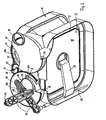
Fig. 2 shows an embodiment of a bellows gas meter partly in perspective and partly in cut-away form, -
Fig. 3 shows the bellows gas meter fromFig. 2 in plan view and likewise in partly cut-away form, -
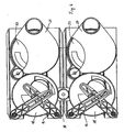
Fig. 4 shows a plan view of two bellows gas meters fromFig. 2 in the assembled state, and -
Fig. 5 shows a further exemplary embodiment of a slot. - According to
Fig. 1 , a bellows gas meter comprises a schematically indicated fire-resistant outer housing 1 which is made of sheet metal, and has an inlet 2 and an outlet 3, and also comprises an inner housing 5, provided with a valve device 4, and a counting mechanism 6, although it is also possible for the latter to be arranged outside the outer housing 1. The inner housing 5, which is, in particular, a plastic housing, comprises two chambers which are arranged adjacent to one another and are separated by a central wall. Each chamber is divided into twomeasuring spaces 8 by a movable diaphragm 7, which is fastened along its circumference in the respective chamber of the inner housing 5, a cover 9 being positioned on the inner housing 5 from the outside in each case. - Each diaphragm 7 bears a
rigid plate 10, on which is articulated a lever 11 which is connected in a rotationally fixed manner to arod 12, which is mounted in the inner housing 5 and extends perpendicularly to the lever 11. Therod 12 is thus rotated in accordance with the diaphragm displacement, brought about the difference in pressure in the two chambers separated by the respective diaphragm 7. - At an end which projects out of the inner housing 5, the
respective rod 12, which rotates back and forth in accordance with the diaphragm displacement, is provided with anarm 13 extending perpendicularly to therod 12. Thearms 13, which can be pivoted via therod 12, each have aslot 14, theslots 14 extending in the direction of the longitudinal axes of thearms 13, crossing over one another and, together, accommodating apin 15 of acrank 16. Thecrank 16 is connected in a rotationally fixed manner to a shaft 17. In accordance with the displacement of the two diaphragms 7, thecrank 16, and thus the shaft 17, is thus rotated via the twoarms 13. - The rotation of the
crank 16 causes an inlet-side valve plate 18 of the valve device 4, said valve plate being connected to the shaft 17, to be rotated along with it. Thevalve plate 18 is arranged in a rotatable manner in relation to the inner housing 5, via an inlet connector 19 of the latter leading to the two chambers of the inner housing 5, and has two openings 20, 21 which have a virtually identical surface area and are arranged radially one behind the other in a circle-sector region. In this case, the opening region of the twoopenings openings valve plate 18, gas flowing in via theopenings valve plate 18. - The inner housing 5 also has an
outlet connector 22, over which is arranged an outlet-side valve plate 23, which is of identical construction to the inlet-side valve plate 18 and hascorresponding openings 20b, 21b. However, the outlet-side valve plate 23 has been rotated through 180° in relation to the inlet-side valve plate 18, with the result that theopenings valve plates valve plates respective pinion pinions common shaft 26. Accordingly, rotation of the inlet-side valve plate 18 results in identical rotation of the outlet-side valve plate 23. - The arrangements of the
openings valve plate - Instead of the toothed gear mechanism used in this way, it is also possible to use a belt drive or the like for
coupling valve plates - The outlet-
side valve plate 23 of the associatedpinion 25 is sealed in relation to the interior of the outer housing 1 via a hood-like outlet covering 27 connected in a sealed manner to theoutlet connector 22, i.e. theshaft 26 is also guided in a sealed manner through the outlet covering 27. The outlet covering 27 has anoutlet connector 28 which leads to the outlet 3 of the outer housing 1 or forms the same. The inlet side of the outer housing 1 is thus separated from the outlet side in terms of pressure. - The counting mechanism 6 may be actuated, for example, via the
common shaft 26, although it is also possible to provide a separate pinion which engages with thevalve plate 18 or thepinion 24 and transmits the movement to the counting mechanism 6. - In the exemplary embodiment illustrated, the
crank 16 comprises abimetallic strip 29 which serves for bringing about temperature compensation. In this case, thebimetallic strip 29 is located essentially over the opening 20a of thevalve plate 18 and rotates therewith. Thebimetallic strip 29 thus has the inflowing gas flowing around it on a permanent basis, so that the temperature compensation takes place virtually instantaneously, as a result of which incorrect measurements are avoided. - If the
bimetallic strip 29 is not used, i.e. no such temperature compensation is to be carried out, thecrank pin 15 may be arranged directly on the inlet-side valve plate 18. However, for the purpose of achieving better force transmission, it is preferred to use a carry-along disc which is separate from the inlet-side valve plate 18. - Quick start-up of the bellows gas meter results in a pressure surge, although the counting mechanism does not respond to this. For this purpose, the outlet-
side valve plate 23 is expediently arranged with axial play beneath the outlet covering 27, with the result that it can lift up briefly under the action of the pressure surge, so that the pressure surge dissipates without moving the diaphragm 7. In this case, correspondingly, the outlet-side valve plate 23 acts as a pressure relief valve. - The inlet and outlet valve formed via the
valve plates valve plates - As is illustrated in
Fig. 4 , it is readily possible, in the case of such a configuration of the bellows gas meter, for two or more parallel measuring units to be coupled to one another in order to achieve higher levels of throughflow or lower throughflow loading, use being made of anintermediate gearwheel 30 in order to synchronize the inlet-side valve plates side valve plates 18 to one another. - The
slots 14 are expediently optimized in order to achieve optimal opening characteristics, i.e. they are widened, for example, in the central region, in order to produce a kind of hysteresis in relation to the movement of thecrank piece 15, which moves along one side of theslot 14 in one movement direction of the diaphragm 7 and moves along the other side of theslot 14 in the other movement direction of the diaphragm 7, seeFigure 5 .
Claims (17)
- Bellows gas meter having an inlet (2), an outlet (3) and an inner housing (5) with two chambers, which are each divided into two measuring spaces (8) by a diaphragm (7), and having a valve device (4) by means of which the measuring spaces (8) are connected to the inlet (2) and outlet (3) in a manner which alternates in dependence on the diaphragm displacement, it being possible for the phase-displaced movement of the two diaphragms (7) to be transmitted to a measuring unit (G), characterized in that the valve device (4) has a rotatable inlet-side and a rotatable outlet-side valve plate (18, 23) and these, on the inlet and outlet sides, have in each case two pairs of openings (20a, 21a, 20b, 21b) which lead to the two respective measuring spaces (8) of a chamber and are located opposite one another in relation to the respective axis of rotation (17) of the valve plate (18, 23), an opening (20a, 20b) adjacent to the outer border and an opening (21a, 21b) adjacent to the axis of rotation (17) being arranged radially one behind the other in a circle-sector region, and the two valve plates (18, 23), which are offset through 180° in respect of their. openings (20a, 21a, 20b, 21b), are coupled to one another in a rotatable manner, it being possible for the inlet-side valve plate (1.8) to be rotated in circulation in accordance with the diaphragm displacement, and the opening region of the openings (20a, 21a, 20b, 21b) of the valve plates (18, 23) extending in each case over approximately 90°.
- Bellows gas meter according to Claim 1, characterized in that the valve plates (18, 23) are toothed around the circumference and are coupled to one another via at least one pinion (24, 25).
- Bellows gas meter according to Claim 1 or 2, characterized in that the inlet-side valve plate (18) can be rotated by means of a crank (16) which engages with a respective slot (14) of a lever arm (13), which can be pivoted in accordance with respective diaphragm displacement.
- Bellows gas meter according to Claim 3, characterized in that the inlet-side valve plate (18) can be rotated via a carry-along element of the crank (16).
- Bellows gas meter according to Claim 3 or 4, characterize in that the slot (14) is shaped in accordance with predetermined valve-opening characteristics.
- Bellows gas meter according to one of Claims 1 to 5, characterized in that arranged over the outlet-side valve plate (23) is a hood-like outlet covering (27.), within which the outlet-side valve plate (23) is arranged with axial play.
- Bellows gas meter according to one of Claims 1 to 6, characterized in that the openings are arranged identically in the inlet-side and outlet-side valve plates (18, 23).
- Bellows gas meter according to Claim 7 characterized in that the inlet-side and outlet-side valve plates (18, 23) are of identical design.
- Bellows gas meter according to one of Claims 1 to 8, characterized in that the inlet-side and outlet-side valve plates (18, 23) are arranged on a respective inlet or outlet connector (19, 22) of the inner housing (5).
- Bellows gas meter according to one of Claims 1 to 9, characterized in that the openings (20a, 21a, 20b, 21b) of the valve plates (18, 23) extend over an angle range 90°.
- Bellows gas meter according to one of Claims 1 to 10, characterized in that a temperature-compensation member (29) is interposed in the kinematic chain from the diaphragm (7) to the inlet-side valve plate (18).
- Bellows gas meter according to Claim 11, characterized in that the temperature-compensation member (29) is a bimetallic strip.
- Bellows gas meter according to Claim 11 or 12, characterized in that the temperature compensation member (29) is part of a crank (16) which rotates the inlet-side valve plate (18).
- Bellows gas meter according to one of Claims 1 to 13, characterized in that two or more inner housings (5) with valve device (4) are arranged one behind the other, the valve plates (18) being synchronized with one another via an intermediate gearwheel (30).
- Bellows gas meter according to one of Claims 1 to 14, characterized in that the valve plates (18, 23) are plastic plates.
- Bellows gas meter according to one of Claims 1 to 14, characterized in that the valve plates (18, 23) are ceramic plates.
- Bellows gas meter according to one of Claims 1 to 16, characterized in that the valve plates (18, 23) arc sandwich plates.
Applications Claiming Priority (2)
| Application Number | Priority Date | Filing Date | Title |
|---|---|---|---|
| DE2003114638 DE10314638B3 (en) | 2003-04-01 | 2003-04-01 | Diaphragm gas meters |
| DE10314638 | 2003-04-01 |
Publications (3)
| Publication Number | Publication Date |
|---|---|
| EP1464931A2 EP1464931A2 (en) | 2004-10-06 |
| EP1464931A3 EP1464931A3 (en) | 2007-12-26 |
| EP1464931B1 true EP1464931B1 (en) | 2012-01-11 |
Family
ID=32842193
Family Applications (1)
| Application Number | Title | Priority Date | Filing Date |
|---|---|---|---|
| EP20040300155 Expired - Lifetime EP1464931B1 (en) | 2003-04-01 | 2004-03-19 | Bellows gas meter |
Country Status (2)
| Country | Link |
|---|---|
| EP (1) | EP1464931B1 (en) |
| DE (1) | DE10314638B3 (en) |
Families Citing this family (5)
| Publication number | Priority date | Publication date | Assignee | Title |
|---|---|---|---|---|
| EP1990613A1 (en) * | 2007-05-08 | 2008-11-12 | Carlos Roman Marron Legarreta | Mechanical temperature compensation gas meter |
| CN105784048B (en) * | 2016-05-17 | 2018-02-16 | 成都秦川物联网科技股份有限公司 | High-accuracy wide-range diaphragm gas meter |
| RU189110U1 (en) * | 2019-01-10 | 2019-05-13 | Акционерное общество Научно-производственное объединение "Электроприбор-Воронеж" (АО НПО "Электроприбор-Воронеж") | Diaphragm gas meter with rotary valve timing |
| RU2696362C1 (en) * | 2019-01-10 | 2019-08-01 | Акционерное общество Научно-производственное объединение "Электроприбор-Воронеж" (АО НПО "Электроприбор-Воронеж") | Method for temperature correction of a membrane gas meter with a rotary gas distribution valve and a device for its implementation |
| PL242792B1 (en) * | 2020-09-02 | 2023-04-24 | Apator Metrix Spolka Akcyjna | Measuring unit of a bellows gas meter |
Family Cites Families (7)
| Publication number | Priority date | Publication date | Assignee | Title |
|---|---|---|---|---|
| DE210658C (en) * | ||||
| GB504427A (en) * | 1938-05-30 | 1939-04-25 | James Herbert Bingham | Improvements in or relating to gas meters |
| GB545636A (en) * | 1940-12-07 | 1942-06-05 | Harry Johnston | An improvement in or relating to valves for gas meters of the dry type |
| US3119264A (en) * | 1961-08-04 | 1964-01-28 | Textron Inc | Temperature compensating means for gas meters |
| FR2549221B1 (en) * | 1983-06-14 | 1986-10-31 | Flonic Sa | GAS METER |
| DE3707164C1 (en) * | 1987-03-06 | 1988-05-19 | Rombach Gmbh Johann B | Concertina-type gas meter |
| DE19501858C2 (en) * | 1995-01-23 | 1996-12-12 | Gmt Gas Mes Und Regeltechnik G | Measuring device for volume measurement |
-
2003
- 2003-04-01 DE DE2003114638 patent/DE10314638B3/en not_active Expired - Fee Related
-
2004
- 2004-03-19 EP EP20040300155 patent/EP1464931B1/en not_active Expired - Lifetime
Also Published As
| Publication number | Publication date |
|---|---|
| EP1464931A2 (en) | 2004-10-06 |
| DE10314638B3 (en) | 2004-10-07 |
| EP1464931A3 (en) | 2007-12-26 |
Similar Documents
| Publication | Publication Date | Title |
|---|---|---|
| FI79182B (en) | STROEMNINGSREGLERANORDNING I EN ENGREPPSVENTIL. | |
| EP1464931A2 (en) | Bellows gas meter | |
| KR20040089719A (en) | Food pressure-cooking device with a rotary locking/unlocking control device | |
| DK159512B (en) | FLUID CONTROLLER | |
| WO2000052366A1 (en) | Variable orifice dual gate valve | |
| EP1325236B2 (en) | Driving mechanism and shut-off valve | |
| EP1028279B1 (en) | Ceramic disc cartridge for mixing fluids in faucets and the like | |
| PL119343B1 (en) | Apparatus for setting the values of angle of torsion of torsional element of the mechanism being in motion or transmitting the motion and for transmitting the information and/or setting signalsija krutil'nogo ehlementa mekhanizma,nakhodjahhegosja v dvizhenii ili peredajuhhego dvizhenie dlja peredachi informacionnykh i/ili regulirovochnykh signalov | |
| KR970066530A (en) | Pressure gauge device | |
| EP0254957A1 (en) | Water mixer tap, of the single-lever type | |
| AU630175B2 (en) | Valve actuator two rotor three position indicator | |
| NO319828B1 (en) | Device for controlling flow in ducts | |
| EP3521701A1 (en) | Gas cock with a safety valve for a gas cooking appliance, and gas cooking appliance incorporating said gas cock | |
| DK159255B (en) | HYDROSTATIC AID CONTROL DEVICES | |
| CN215524817U (en) | Protective shell, hopper driving device and combined scale | |
| US5317927A (en) | Measuring device | |
| EP0253133B1 (en) | Internal gear hydraulic pump | |
| KR200173851Y1 (en) | Gas meter | |
| KR20080083395A (en) | Actuator with non-penetrating waterproof switch | |
| JPH11248506A (en) | Diaphragm gas meter | |
| ES2050891T3 (en) | ROTARY DISTRIBUTOR. | |
| PL196156B1 (en) | Crank mechanism | |
| GB2102887A (en) | Fluid-pressure actuator operating rotatable shaft | |
| KR100839142B1 (en) | Slip type zero adjustment device | |
| PL147238B1 (en) | Flexible coupling with torque limiter |
Legal Events
| Date | Code | Title | Description |
|---|---|---|---|
| PUAI | Public reference made under article 153(3) epc to a published international application that has entered the european phase |
Free format text: ORIGINAL CODE: 0009012 |
|
| AK | Designated contracting states |
Kind code of ref document: A2 Designated state(s): AT BE BG CH CY CZ DE DK EE ES FI FR GB GR HU IE IT LI LU MC NL PL PT RO SE SI SK TR |
|
| AX | Request for extension of the european patent |
Extension state: AL HR LT LV MK |
|
| PUAL | Search report despatched |
Free format text: ORIGINAL CODE: 0009013 |
|
| AK | Designated contracting states |
Kind code of ref document: A3 Designated state(s): AT BE BG CH CY CZ DE DK EE ES FI FR GB GR HU IE IT LI LU MC NL PL PT RO SE SI SK TR |
|
| AX | Request for extension of the european patent |
Extension state: AL LT LV MK |
|
| 17P | Request for examination filed |
Effective date: 20080626 |
|
| AKX | Designation fees paid |
Designated state(s): FR GB IT TR |
|
| REG | Reference to a national code |
Ref country code: DE Ref legal event code: 8566 |
|
| GRAP | Despatch of communication of intention to grant a patent |
Free format text: ORIGINAL CODE: EPIDOSNIGR1 |
|
| GRAC | Information related to communication of intention to grant a patent modified |
Free format text: ORIGINAL CODE: EPIDOSCIGR1 |
|
| GRAS | Grant fee paid |
Free format text: ORIGINAL CODE: EPIDOSNIGR3 |
|
| GRAA | (expected) grant |
Free format text: ORIGINAL CODE: 0009210 |
|
| AK | Designated contracting states |
Kind code of ref document: B1 Designated state(s): FR GB IT TR |
|
| REG | Reference to a national code |
Ref country code: GB Ref legal event code: FG4D |
|
| PLBE | No opposition filed within time limit |
Free format text: ORIGINAL CODE: 0009261 |
|
| STAA | Information on the status of an ep patent application or granted ep patent |
Free format text: STATUS: NO OPPOSITION FILED WITHIN TIME LIMIT |
|
| PG25 | Lapsed in a contracting state [announced via postgrant information from national office to epo] |
Ref country code: IT Free format text: LAPSE BECAUSE OF FAILURE TO SUBMIT A TRANSLATION OF THE DESCRIPTION OR TO PAY THE FEE WITHIN THE PRESCRIBED TIME-LIMIT Effective date: 20120111 |
|
| 26N | No opposition filed |
Effective date: 20121012 |
|
| REG | Reference to a national code |
Ref country code: FR Ref legal event code: ST Effective date: 20121130 |
|
| GBPC | Gb: european patent ceased through non-payment of renewal fee |
Effective date: 20120411 |
|
| PG25 | Lapsed in a contracting state [announced via postgrant information from national office to epo] |
Ref country code: GB Free format text: LAPSE BECAUSE OF NON-PAYMENT OF DUE FEES Effective date: 20120411 Ref country code: FR Free format text: LAPSE BECAUSE OF NON-PAYMENT OF DUE FEES Effective date: 20120402 |
|
| PG25 | Lapsed in a contracting state [announced via postgrant information from national office to epo] |
Ref country code: TR Free format text: LAPSE BECAUSE OF FAILURE TO SUBMIT A TRANSLATION OF THE DESCRIPTION OR TO PAY THE FEE WITHIN THE PRESCRIBED TIME-LIMIT Effective date: 20120111 |