EP1464857A1 - Friction disk with a groove in its friction layer - Google Patents
Friction disk with a groove in its friction layer Download PDFInfo
- Publication number
- EP1464857A1 EP1464857A1 EP04009930A EP04009930A EP1464857A1 EP 1464857 A1 EP1464857 A1 EP 1464857A1 EP 04009930 A EP04009930 A EP 04009930A EP 04009930 A EP04009930 A EP 04009930A EP 1464857 A1 EP1464857 A1 EP 1464857A1
- Authority
- EP
- European Patent Office
- Prior art keywords
- disk
- groove
- grooves
- rolling
- template
- Prior art date
- Legal status (The legal status is an assumption and is not a legal conclusion. Google has not performed a legal analysis and makes no representation as to the accuracy of the status listed.)
- Withdrawn
Links
- 230000005540 biological transmission Effects 0.000 claims abstract description 12
- 238000005096 rolling process Methods 0.000 description 57
- 238000000034 method Methods 0.000 description 22
- 125000006850 spacer group Chemical group 0.000 description 18
- 238000013461 design Methods 0.000 description 17
- 238000004140 cleaning Methods 0.000 description 7
- 238000004519 manufacturing process Methods 0.000 description 6
- 239000000463 material Substances 0.000 description 5
- 235000012773 waffles Nutrition 0.000 description 5
- 239000012876 carrier material Substances 0.000 description 4
- 238000000926 separation method Methods 0.000 description 4
- 238000004026 adhesive bonding Methods 0.000 description 3
- 239000003921 oil Substances 0.000 description 3
- 229910000831 Steel Inorganic materials 0.000 description 2
- 206010043183 Teething Diseases 0.000 description 2
- 238000011161 development Methods 0.000 description 2
- 230000018109 developmental process Effects 0.000 description 2
- 238000010438 heat treatment Methods 0.000 description 2
- 238000003475 lamination Methods 0.000 description 2
- 239000010959 steel Substances 0.000 description 2
- 230000036346 tooth eruption Effects 0.000 description 2
- 239000011248 coating agent Substances 0.000 description 1
- 238000000576 coating method Methods 0.000 description 1
- 230000006835 compression Effects 0.000 description 1
- 238000007906 compression Methods 0.000 description 1
- 238000010276 construction Methods 0.000 description 1
- 238000011109 contamination Methods 0.000 description 1
- 238000001816 cooling Methods 0.000 description 1
- 230000001419 dependent effect Effects 0.000 description 1
- 239000010432 diamond Substances 0.000 description 1
- 230000008030 elimination Effects 0.000 description 1
- 238000003379 elimination reaction Methods 0.000 description 1
- 239000002657 fibrous material Substances 0.000 description 1
- 239000002783 friction material Substances 0.000 description 1
- 239000007788 liquid Substances 0.000 description 1
- 239000000314 lubricant Substances 0.000 description 1
- 239000010687 lubricating oil Substances 0.000 description 1
- 238000005461 lubrication Methods 0.000 description 1
- 238000005259 measurement Methods 0.000 description 1
- 239000002184 metal Substances 0.000 description 1
- 239000002689 soil Substances 0.000 description 1
- 238000003860 storage Methods 0.000 description 1
- 230000000153 supplemental effect Effects 0.000 description 1
- 238000012546 transfer Methods 0.000 description 1
Images


Classifications
-
- B—PERFORMING OPERATIONS; TRANSPORTING
- B21—MECHANICAL METAL-WORKING WITHOUT ESSENTIALLY REMOVING MATERIAL; PUNCHING METAL
- B21H—MAKING PARTICULAR METAL OBJECTS BY ROLLING, e.g. SCREWS, WHEELS, RINGS, BARRELS, BALLS
- B21H7/00—Making articles not provided for in the preceding groups, e.g. agricultural tools, dinner forks, knives, spoons
- B21H7/18—Making articles not provided for in the preceding groups, e.g. agricultural tools, dinner forks, knives, spoons grooved pins; Rolling grooves, e.g. oil grooves, in articles
-
- F—MECHANICAL ENGINEERING; LIGHTING; HEATING; WEAPONS; BLASTING
- F16—ENGINEERING ELEMENTS AND UNITS; GENERAL MEASURES FOR PRODUCING AND MAINTAINING EFFECTIVE FUNCTIONING OF MACHINES OR INSTALLATIONS; THERMAL INSULATION IN GENERAL
- F16D—COUPLINGS FOR TRANSMITTING ROTATION; CLUTCHES; BRAKES
- F16D13/00—Friction clutches
- F16D13/58—Details
- F16D13/60—Clutching elements
- F16D13/64—Clutch-plates; Clutch-lamellae
-
- F—MECHANICAL ENGINEERING; LIGHTING; HEATING; WEAPONS; BLASTING
- F16—ENGINEERING ELEMENTS AND UNITS; GENERAL MEASURES FOR PRODUCING AND MAINTAINING EFFECTIVE FUNCTIONING OF MACHINES OR INSTALLATIONS; THERMAL INSULATION IN GENERAL
- F16D—COUPLINGS FOR TRANSMITTING ROTATION; CLUTCHES; BRAKES
- F16D13/00—Friction clutches
- F16D13/58—Details
- F16D13/60—Clutching elements
- F16D13/64—Clutch-plates; Clutch-lamellae
- F16D13/648—Clutch-plates; Clutch-lamellae for clutches with multiple lamellae
-
- F—MECHANICAL ENGINEERING; LIGHTING; HEATING; WEAPONS; BLASTING
- F16—ENGINEERING ELEMENTS AND UNITS; GENERAL MEASURES FOR PRODUCING AND MAINTAINING EFFECTIVE FUNCTIONING OF MACHINES OR INSTALLATIONS; THERMAL INSULATION IN GENERAL
- F16D—COUPLINGS FOR TRANSMITTING ROTATION; CLUTCHES; BRAKES
- F16D13/00—Friction clutches
- F16D13/58—Details
- F16D13/72—Features relating to cooling
-
- F—MECHANICAL ENGINEERING; LIGHTING; HEATING; WEAPONS; BLASTING
- F16—ENGINEERING ELEMENTS AND UNITS; GENERAL MEASURES FOR PRODUCING AND MAINTAINING EFFECTIVE FUNCTIONING OF MACHINES OR INSTALLATIONS; THERMAL INSULATION IN GENERAL
- F16D—COUPLINGS FOR TRANSMITTING ROTATION; CLUTCHES; BRAKES
- F16D69/00—Friction linings; Attachment thereof; Selection of coacting friction substances or surfaces
- F16D2069/004—Profiled friction surfaces, e.g. grooves, dimples
Definitions
- the invention concerns a device for forming at least one groove in a friction layer of a covered plate for a force transmission aggregate, in particular for a clutch disk according to Claim 1, as well as a process for forming at least one groove in a friction layer of a friction plate for a force transmission aggregate, in particular for a clutch disk according to Claim 17.
- Disk clutches generally include a plurality of disks, which can be produced using the device described below or, as the case may be, using the process described below.
- a first group of disks of this type is provided upon a disk carrier fixed against rotation and sliding, and a second group is provided drivable upon a drive hub.
- the disks of the two groups intermesh or interdigitate in each other in the manner of gear teeth.
- the two groups are slideable relative to each other in the axial direction and thereby can be brought pair-wise into or out of engagement.
- a disk clutch of the above-described type is described, for example, in DE 199 06 980 A1.
- the individual disks are preferably formed ring-shaped. Distinctions are made between so-called covered disks and so-called steel disks. Covered disks are in general constructed in sandwich-like manner.
- the base element for a ring-shaped covered disk of this type is a ring carrier, which is comprised for example of steel and is produced preferably by stamping.
- This sheet metal carrier carries a friction layer on one or both of its ring surfaces. This layer is comprised in general of a fibrous material, such as paper, or is produced from a paper-like material.
- disk clutches or disk brakes in which the disk is continuous, that is, is produced as a unitary piece of a friction material.
- a lubricant preferably oil
- the above-mentioned layer exhibits a sponge-like structure.
- the non-pressured condition that is, when there is no contact between adjacent disks, a certain amount of oil storage is taking place, which is again given off or released during actuation and the compression occurring in conjunction therewith.
- the grooves can be designed or formed in the most diverse design and manner. Depending upon the function to be fulfilled, these grooves can be in the form of rays, lines, curves, criss-cross and the like. Further, the most diverse groove cross-sectional shapes and sizes can be utilized.
- a material removing process step of this type has been found to be disadvantageous in many respects.
- a continuous manufacturing process is thus not possible.
- this type of material removing process exhibits the disadvantage, that the removed material disperses and soils the disk pre-form or the machine or machine parts.
- the invention is thus concerned with the task of providing a device or, as the case may be, a process for introduction of grooves into a friction layer of a covered disk, with which, or as the case may be, in which the above described problems no longer occur.
- a continuous manufacturing process should be made possible with high speed.
- the transfer as well as the manipulation of work pieces should occur in simple manner, and contamination should be substantially eliminated.
- the process in particular on the basis of the elimination of the above mentioned disadvantages, a cost reduction is achieved.
- the task is inventively solved by a device or, as the case may be, a process for introduction of at least one groove in a friction layer of a friction disk or a force transmission aggregate, in particular for a disk clutch, with the features of the characterizing portion of Claim 1.
- the inventive process is based on the idea, that the at least one groove is introduced by a rolling or turning process.
- the device includes a rolling device with at least one rolling arm for rolling the at least one groove.
- the disk is moved under the corresponding rolling device or the rolling device is moved over the disk.
- a process of this type can be integrated in simple manner into a continuous manufacturing process.
- the invention in particular envisions that the one or more grooves are introduced immediately subsequent to the process of gluing or lamination of the friction layer to the carrier material. It has been found that the introduction of the groove via the rolling process is to be carried out at elevated temperature, in order to produce high value grooves. Since the process of gluing the friction layer to the carrier material usually occurs at elevated temperature, the above described rolling process is preferably incorporated into the existing production process. It has further been found that a process of this type is suitable both for the introduction of grooves into a disk provided on one side with a friction layer, as well as for introduction into disks.provided on both sides with a frictional layer.
- the rolling device includes,a drive shaft rotatable about a rotation axis, co-axially upon which is provided at least one essentially circular shaped template disk, the disk defined by an outer diameter and an outer circumference or outer contour.
- the at least one rolling arm is thus formed by the outer circumference of the at least one circular shaped template disk.
- template disks provided side-by-side or adjacent to each other are spaced apart with the aid of appropriate spacer rings of, in certain cases, varying thicknesses.
- a device of this type is simple in design and manufacture, and therewith is economical. Further, the template disks as well as the spacer rings are easily manufactured and therewith also economical.
- grooves in a friction layer which preferably extend essentially linearly.
- the manufacture of curved grooves is only possible to a limited extent when using this device, since the circumference of the template disks must exhibit a corresponding curvature.
- groove designs can be produced in simple manner with crisscrossing grooves formed of essentially linearly groove tracks, in which the respective disk passes multiple times through the rolling process, however relative to the preceding process step is rotated by a certain angular amount with respect to the rolling device.
- the rolling device includes a drum rotatable about a rotation axis with an outer circumference surface, upon which again one rolling flange or multiple rolling flanges are provided. Since a drum of this type, in contrast to the above-described rolling disk, extends in the axial direction, rolling flanges can be provided and arranged in any type and manner. In particular, rolling flanges are possible which extend only partially in the axial direction, or which extend in any other mode and manner, even extending slanted or even curved.
- the outer circumference surface is formed as a cylinder.
- the introduction of the grooves corresponds then substantially to the above described embodiment. It is however essentially also possible, that the outer circumference surface is formed by the side surfaces of a cylinder with a multi-sided base shape.
- the corresponding rolling flange cross-sections are of various design.
- the corresponding cross sections can be of semicircular design, triangular design, trapezoidal design or a right-angled design, depending upon the cross-section of the groove to be produced. It is readily apparent that the cross sectional shape of the rolling flanges in both of the above described rolling devices can be varied.
- the invention envisions the provision of a heating device for heating the rolling flanges.
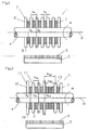
- the first illustrative embodiment of a rolling device 1 is based upon a drive shaft 4 mounted rotatably about a rotation axis R (rotation direction ⁇ ). Seated upon this drive shaft 4 are arranged, co-axially, a total of seven template disk rings 2 .
- the individual template disk rings 2 are spaced apart via intermediate spacer rings 3 arranged co-axially in same manner.
- the total disk set is comprised of template disks 2 and spacer rings 3 which are essentially rigidly connected with the drive shaft 4 with the aid of - here not shown - fixing devices.
- a fixing device of this kind can be of a design for example such that the outer template disk 2 is screwed onto the drive shaft 4 .
- a rotation in the circumferential direction can be prevented for example thereby, that the template disk 2 and in certain cases also the spacer rings 3 have an internal teething and the drive shaft 4 exhibits an external teething, which engage in each other.
- the outer diameter d F of the template disks 2 is larger than the outer diameter d D of the spacer rings 3 .
- the thickness a D of the spacer rings 3 provides the separation a N of the template disks 2 .
- the template disks 2 are curved arc-like at their outer circumference 8 . Since the outer circumference of the respective template disks 2 represent the respective rolling flanges 7 for rolling in of the groove, it can be seen that the groove to be introduced is to exhibit a semicircular bow-shaped cross sectional design.
- the rolling device 1 represented in Figure 1 is moved over the covered disk under a pre-tensioned force (pressure) or, as the case may be, in the converse the covered disk may be guided correspondingly under'the rolling device 1 .
- a pre-tensioned force pressure
- the needed pre-tension amount depends upon the type and thickness of the friction layer as well as the type and the cross section of the groove to be introduced. Further care is to be taken that the friction layer is not already hardened or cured. It has been found particularly advantageous to carry out the turning process immediately subsequent to the process of gluing or lamination of the friction layer with the carrier material.
- This cleaning device 5 can in the present case be designed as a brush device 6 .
- Rinsing or vacuum devices are likewise conceivable.
- the illustrative embodiment represented in Figure 2 shows a further development of the present described illustrative embodiment according to Figure 1.
- the rolling device 11 is comprised, as in the above-described illustrative embodiment of a drive shaft 4 rotatable ( ⁇ ) about a rotation axis R with co-axially arranged circular-shaped template disks 2 , 12 and spacer rings 3 , 13 .
- the rolling flange cross section 17 has a semicircular arc shaped form at the circumference 18 of the respective template disks 2 , 12 .
- a cleaning device 5 with brushes 6 is provided.
- the presently described illustrative embodiment differs with respect to the previously described example essentially thereby, that the spacer rings 3 , 13 exhibit varying thicknesses.
- the corresponding dimensions or measurements are indicated in the drawing with the reference symbol a D1 or, as the case may be, a D2 .
- a further departure from the previously described example is comprised therein, that the diameters of the circular shaped template disks 2 , 12 also differ.
- Four of the circular shaped template disks 2 exhibit a diameter d F1
- two template disks 12 exhibit diameter d F2 .
- This illustrative embodiment shows that, in a working step, grooves of different depths and with varying spacings to each other can be introduced into the friction layer.
- the rolling device 21 shown in Figure 3 is based, as in the above-described examples, upon a drive shaft 4 mounted rotatably ( ⁇ ) about a rotation axis R with a plurality of circular ring shaped template disks 22a, 22b, 22c, 22d, 22e and 22f , which again are spaced apart by means of'appropriate spacer rings 3 , and seated co-axial upon the drive shaft 4 . From the representation according to Figure 3 one can further see rolling flanges with diverse designs of cross sections in the area of the outer circumference of the respective template disks 22a ...
- Two of the rolling flange cross sections exhibit, as in the above-described example, a semicircular arc shaped design 27c , two further exhibit a triangular shape 27a and 27b , two further exhibit trapezoid shaped design 27d, 27e and a last one exhibits a right-angled or squared-off design 27f .
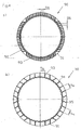
- Figure 4 illustrates, on the basis of representations of top views upon the friction disks with grooves, the types of groove patterns that can be produced with the aid of one or more of the previously described devices according to Figure 1 through 3.
- Figure 4 a) shows a groove image or pattern in which seven grooves are provided running linearly next to each other. Seven similarly arranged grooves 92 cross the above-described group of grooves 93 at an angle of about 90°. The separation of the respective grooves is indicated in the figure by the reference symbol a N .
- Figure 4 b shows a groove pattern in a friction layer 91 of a friction disk 90 in which three groups of grooves 93, 94 and 95 (individual grooves with spacing a N ) are oriented concentrically, offset at an angle of 60° relative to each other.
- Figure 4 c) shows a so-called waffle groove pattern, in which two groups of grooves 92 and 93 (here the individual grooves of the respective groups) run crossing at right angles with a separation of a N1 or, as the case may be, a N2 .
- Figure 4 d shows a groove pattern changed slightly in comparison to the above groove designs, wherein the respective grooves of the corresponding grooves run at an angle of approximately 45° to each other. All groove patterns described previously and shown in Figure 4 can be produced in simple manner thereby, that a device for example as shown in Figure 1 is directed multiple times over the particular covered disk 90 , however in each subsequent step is respectively rotated about the corresponding above indicated angle.
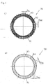
- FIG. 5 shows a further illustrative embodiment of an inventive rolling device 31 .
- This rolling device 31 according to Figure 5 is not formed as in the preceding described illustrative embodiments according to Figures 1 through 3 of disk sets with multiple template disks and spacing rings, but rather is comprised of a drum 32 rotatable about a rotation axis R (direction of rotation ⁇ ) with a cylindrical shaped circumference surface 38 .
- a drum 32 rotatable about a rotation axis R (direction of rotation ⁇ ) with a cylindrical shaped circumference surface 38 .
- Upon the circumference surface 38 of the drum 32 are provided, in the present example, three rolling flanges 37a, 37b and 37c which can run curved over the circumference in almost any desired manner.
- An illustrative embodiment of this type is suitable for introducing other, in particular also non-linear, groove paths or patterns in the friction layer 91 of a covered disk 90 .
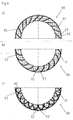
- Figure 6 a shows a friction layer with two groups of grooves.
- the grooves 96 of the first group run along secants, which thus cut into or,across the ring shaped covered disk 90 .
- the other group of grooves includes two subgroups.
- the grooves 92 of the one subgroup run parallel to a radius of the ring shaped disk 90 , the grooves 93 of the other subgroup perpendicular thereto. In this manner there is produced a grid.
- the second group of grooves 92, 93 runs linearly, it is comparatively difficult to introduce these grooves with one of the devices according to Figures 1 through 3.
- the device according to Figure 5 is however particularly suitable therefore.
- the groove image according to Figure 6 b) is formed similarly to the groove pattern according to Figure 6 a). Supplemental to the group of grooves 92, 93 , which form a grid pattern, there are also provided bow-shaped running grooves.
- the groove pattern according to Figure 6 c) differs from this essentially thereby, that further bow-shaped grooves 98 are provided, which cut into or across the above-described bow-shaped grooves 97 .
- Both groove patterns according to Figure 6 b) and c) can be produced by a device according to Figure 5.
Landscapes
- Engineering & Computer Science (AREA)
- General Engineering & Computer Science (AREA)
- Mechanical Engineering (AREA)
- Life Sciences & Earth Sciences (AREA)
- Agronomy & Crop Science (AREA)
- Mechanical Operated Clutches (AREA)
- Shaping Metal By Deep-Drawing, Or The Like (AREA)
- Friction Gearing (AREA)
Abstract
The invention refers to a friction disk (90) for a force transmission aggregate, in particular for a disk clutch having at least one groove (92, 93) in its friction layer (91). According to the invention at least one of that at least one groove (92, 93.) is of triangular, semicircular or trapezoid cross sectional geometry. <IMAGE>
Description
The invention concerns a device for forming at least one
groove in a friction layer of a covered plate for a force
transmission aggregate, in particular for a clutch disk according
to Claim 1, as well as a process for forming at least
one groove in a friction layer of a friction plate for a force
transmission aggregate, in particular for a clutch disk according
to Claim 17.
Disk clutches generally include a plurality of disks, which
can be produced using the device described below or, as the
case may be, using the process described below. Conventionally
a first group of disks of this type is provided upon a disk
carrier fixed against rotation and sliding, and a second group
is provided drivable upon a drive hub. The disks of the two
groups intermesh or interdigitate in each other in the manner
of gear teeth. The two groups are slideable relative to each
other in the axial direction and thereby can be brought pair-wise
into or out of engagement. A disk clutch of the above-described
type is described, for example, in DE 199 06 980 A1.
The individual disks are preferably formed ring-shaped. Distinctions
are made between so-called covered disks and so-called
steel disks. Covered disks are in general constructed
in sandwich-like manner. The base element for a ring-shaped
covered disk of this type is a ring carrier, which is comprised
for example of steel and is produced preferably by
stamping. This sheet metal carrier carries a friction layer on
one or both of its ring surfaces. This layer is comprised in
general of a fibrous material, such as paper, or is produced
from a paper-like material.
There are however also disk clutches or disk brakes, in which
the disk is continuous, that is, is produced as a unitary
piece of a friction material.
In the above-mentioned force transmission aggregate, the lubrication
and cooling of the individual construction components
plays an essential role. For this reason a lubricant,
preferably oil, is provided between the individual disks. In
order to hold the lubricating oil for a predetermined period
on the friction surfaces of the disks or, as the case may be,
to be able to release oil, the above-mentioned layer exhibits
a sponge-like structure. In the non-pressured condition, that
is, when there is no contact between adjacent disks, a certain
amount of oil storage is taking place, which is again given
off or released during actuation and the compression occurring
in conjunction therewith. Since the sponge-like structure of
the friction layer is however not adequate by itself to ensure
that the functional requirements of the force transmission aggregate
will be satisfied, it is within the state of the art
to introduce grooves into the friction layer of the disk. Depending
upon the intended employment of the respective force
transmission aggregates, the grooves can be designed or formed
in the most diverse design and manner. Depending upon the
function to be fulfilled, these grooves can be in the form of
rays, lines, curves, criss-cross and the like. Further, the
most diverse groove cross-sectional shapes and sizes can be
utilized.
According to the state of the art, processes are employed for
producing among other things of the above-described grooves,
in which the friction layer is removed to define the groove
contour.
A material removing process step of this type has been found
to be disadvantageous in many respects. In particular, it is
not possible in accordance with this process to apply the
friction layer upon the carrier material and to introduce the
grooves in a single process step. A continuous manufacturing
process is thus not possible. Besides this, this type of material
removing process exhibits the disadvantage, that the removed
material disperses and soils the disk pre-form or the
machine or machine parts.
From the state of the art it is further known to introduce the
grooves by a press or stamping process. This is however associated
with the disadvantage that the necessary groove depth
cannot be achieved, or can be achieved only with great difficulty.
The invention is thus concerned with the task of providing a
device or, as the case may be, a process for introduction of
grooves into a friction layer of a covered disk, with which,
or as the case may be, in which the above described problems
no longer occur. In particular, a continuous manufacturing
process should be made possible with high speed. The transfer
as well as the manipulation of work pieces should occur in
simple manner, and contamination should be substantially
eliminated. Beyond this, in accordance with the device or, as
the case may be, the process, in particular on the basis of
the elimination of the above mentioned disadvantages, a cost
reduction is achieved.
The task is inventively solved by a device or, as the case may
be, a process for introduction of at least one groove in a
friction layer of a friction disk or a force transmission aggregate,
in particular for a disk clutch, with the features of
the characterizing portion of Claim 1.
Advantageous embodiments and further developments of the invention
are set forth in the dependent claims.
The inventive process is based on the idea, that the at least
one groove is introduced by a rolling or turning process. Accordingly,
the device includes a rolling device with at least
one rolling arm for rolling the at least one groove.
During the rolling process the disk is moved under the corresponding
rolling device or the rolling device is moved over
the disk.
A process of this type can be integrated in simple manner into
a continuous manufacturing process. The invention in particular
envisions that the one or more grooves are introduced immediately
subsequent to the process of gluing or lamination of
the friction layer to the carrier material. It has been found
that the introduction of the groove via the rolling process is
to be carried out at elevated temperature, in order to produce
high value grooves. Since the process of gluing the friction
layer to the carrier material usually occurs at elevated temperature,
the above described rolling process is preferably
incorporated into the existing production process. It has further
been found that a process of this type is suitable both
for the introduction of grooves into a disk provided on one
side with a friction layer, as well as for introduction into
disks.provided on both sides with a frictional layer.
In the following a description will be provided as to the mode
and manner in which the inventive device can be constructed in
advantageous manner. A first particularly advantageous embodiment
of the invention envisions that the rolling device includes,a
drive shaft rotatable about a rotation axis, co-axially
upon which is provided at least one essentially circular
shaped template disk, the disk defined by an outer diameter
and an outer circumference or outer contour. The at least
one rolling arm is thus formed by the outer circumference of
the at least one circular shaped template disk. For almost any
conceivable groove design to be introduced into a disk, there
can be produced in this manner in the shortest possible time a
device for introduction of the groove in the friction layer,
in which simply one or more template disks are appropriately
provided upon the drive shaft. A set of disks of this type is
easy to change out.
In order to be able to introduce grooves in various separations
in the friction layer of the respective covered disks,
it is envisioned in accordance with the invention, that template
disks provided side-by-side or adjacent to each other
are spaced apart with the aid of appropriate spacer rings of,
in certain cases, varying thicknesses. A device of this type
is simple in design and manufacture, and therewith is economical.
Further, the template disks as well as the spacer rings
are easily manufactured and therewith also economical.
As has already been described in detail, depending upon the
intended use it may be necessary to introduce the grooves into
the friction layer with varying groove depths. This also is
easily accomplished in the present described rolling device
using one or more template disk set spaced apart by spacer
rings in simple manner. Essentially, template disks with (in
certain cases, small amount) varying diameters are seated upon
the drive shaft.
With the aid of a device described herein comprising template
disks and spacer rings, it is possible to introduce grooves in
a friction layer, which preferably extend essentially linearly.
The manufacture of curved grooves is only possible to a
limited extent when using this device, since the circumference
of the template disks must exhibit a corresponding curvature.
However, in accordance with one variant of the presently described
embodiment, groove designs can be produced in simple
manner with crisscrossing grooves formed of essentially linearly
groove tracks, in which the respective disk passes multiple
times through the rolling process, however relative to the
preceding process step is rotated by a certain angular amount
with respect to the rolling device.
Almost any conceivable groove pattern or design can be
achieved with a rolling device of the following described embodiment:
In this embodiment the rolling device includes a
drum rotatable about a rotation axis with an outer circumference
surface, upon which again one rolling flange or multiple
rolling flanges are provided. Since a drum of this type, in
contrast to the above-described rolling disk, extends in the
axial direction, rolling flanges can be provided and arranged
in any type and manner. In particular, rolling flanges are
possible which extend only partially in the axial direction,
or which extend in any other mode and manner, even extending
slanted or even curved.
In the simplest case, the outer circumference surface is
formed as a cylinder. The introduction of the grooves corresponds
then substantially to the above described embodiment.
It is however essentially also possible, that the outer circumference
surface is formed by the side surfaces of a cylinder
with a multi-sided base shape.
It is further envisioned in accordance with the invention that
the corresponding rolling flange cross-sections are of various
design. In particular, the corresponding cross sections can be
of semicircular design, triangular design, trapezoidal design
or a right-angled design, depending upon the cross-section of
the groove to be produced. It is readily apparent that the
cross sectional shape of the rolling flanges in both of the
above described rolling devices can be varied.
As already described in detail in the preceding sections, it
is advantageous to form the grooves in the friction layer at
elevated temperatures. For this reason the invention envisions
the provision of a heating device for heating the rolling
flanges.
It has further been found to be advantageous to provide a
cleaning device for cleaning the rolling device and/or the
rolling flanges, even though the presently described inventive
process is not a material removing process.
Four illustrative embodiments are shown in the figures and are
described in greater detail in the following.
There is shown:
- Figure 1
- an axial segment of a first inventive embodiment of an inventive device for introduction of grooves in a friction layer of a friction disk for a force transmission aggregate, in particular for a disk clutch
- Figure
- 2 an axial segment of a second inventive embodiment of an inventive device for introduction of grooves of various depths and in various spacings from each other in the friction layer of a covered disk for a force transmission aggregate, in particular for a disk clutch
- Figure 3
- an axial segment of a third inventive embodiment of an inventive device for introduction of grooves of various cross section geometry in the friction layer of a covered disk for a force transmission aggregate, in particular for a disk clutch
- Figure 4
- a top view upon diverse covered disks with grooves
for a disk clutch
- groove images of grooves, which can be produced
with the aid of one or more of the devices according
to Figures 1 through 3 -
- a) cross shaped groove image
- b) ray shaped groove image
- c) waffle groove image
- d) square or diamond image
- groove images of grooves, which can be produced
with the aid of one or more of the devices according
to Figures 1 through 3 -
- Figure 5
- a perspective view a fourth illustrative embodiment of an inventive device for introduction of nonlinear grooves in a friction layer of a covered disk for a force transmission aggregate, in particular for a disk clutch
- Figure 6
- a top view upon diverse cover layers with grooves
for a disk clutch
- groove images of grooves, which can be produced
with the aid of a device according to Figure 5 -
- a) waffle groove image with grooves arranged with non-concentric ray shape
- b) waffle groove image with ray shaped arranged blade-like curved grooves
- c) waffle groove image with counter-running arranged blade like radiating grooves.
- groove images of grooves, which can be produced
with the aid of a device according to Figure 5 -
The first illustrative embodiment of a rolling device 1, shown
in Figure 1, is based upon a drive shaft 4 mounted rotatably
about a rotation axis R (rotation direction ω). Seated upon
this drive shaft 4 are arranged, co-axially, a total of seven
template disk rings 2. The individual template disk rings 2
are spaced apart via intermediate spacer rings 3 arranged co-axially
in same manner. The total disk set is comprised of
template disks 2 and spacer rings 3 which are essentially rigidly
connected with the drive shaft 4 with the aid of - here
not shown - fixing devices. A fixing device of this kind can
be of a design for example such that the outer template disk 2
is screwed onto the drive shaft 4. A rotation in the circumferential
direction can be prevented for example thereby, that
the template disk 2 and in certain cases also the spacer rings
3 have an internal teething and the drive shaft 4 exhibits an
external teething, which engage in each other.
For a person of ordinary skill it is readily apparent that the
outer diameter dF of the template disks 2 is larger than the
outer diameter dD of the spacer rings 3. The thickness aD of
the spacer rings 3 provides the separation aN of the template
disks 2.
It can further be seen from Figure 1 that the template disks 2
are curved arc-like at their outer circumference 8. Since the
outer circumference of the respective template disks 2 represent
the respective rolling flanges 7 for rolling in of the
groove, it can be seen that the groove to be introduced is to
exhibit a semicircular bow-shaped cross sectional design.
For introducing the grooves in the friction layer of a friction
disk the rolling device 1 represented in Figure 1 is
moved over the covered disk under a pre-tensioned force (pressure)
or, as the case may be, in the converse the covered disk
may be guided correspondingly under'the rolling device 1. It
is to be noted that the needed pre-tension amount depends upon
the type and thickness of the friction layer as well as the
type and the cross section of the groove to be introduced.
Further care is to be taken that the friction layer is not already
hardened or cured. It has been found particularly advantageous
to carry out the turning process immediately subsequent
to the process of gluing or lamination of the friction
layer with the carrier material.
It has further been found to be of advantage to provide a
cleaning device for cleaning the rolling device 1 and in particular
the rolling flanges 7. This cleaning device 5 can in
the present case be designed as a brush device 6. Rinsing or
vacuum devices (with gaseous or liquid medium) are likewise
conceivable.
The illustrative embodiment represented in Figure 2 shows a
further development of the present described illustrative embodiment
according to Figure 1. The rolling device 11 is comprised,
as in the above-described illustrative embodiment of a
drive shaft 4 rotatable (ω) about a rotation axis R with co-axially
arranged circular-shaped template disks 2, 12 and
spacer rings 3, 13. As in the above-described case the rolling
flange cross section 17 has a semicircular arc shaped form at
the circumference 18 of the respective template disks 2, 12.
Similarly, analogous to the above-described illustrative embodiment,
a cleaning device 5 with brushes 6 is provided.
The presently described illustrative embodiment differs with
respect to the previously described example essentially
thereby, that the spacer rings 3, 13 exhibit varying thicknesses.
The corresponding dimensions or measurements are indicated
in the drawing with the reference symbol aD1 or, as the
case may be, aD2. A further departure from the previously described
example is comprised therein, that the diameters of
the circular shaped template disks 2, 12 also differ. Four of
the circular shaped template disks 2 exhibit a diameter dF1,
two template disks 12 exhibit diameter dF2. This illustrative
embodiment shows that, in a working step, grooves of different
depths and with varying spacings to each other can be introduced
into the friction layer.
From Figure 3 it can be seen that not only can grooves of different
spacing and depths be introduced in a friction layer
with the inventive device, but rather also those with diverse
cross sectional geometry. The rolling device 21 shown in Figure
3 is based, as in the above-described examples, upon a
drive shaft 4 mounted rotatably (ω) about a rotation axis R
with a plurality of circular ring shaped template disks 22a,
22b, 22c, 22d, 22e and 22f, which again are spaced apart by
means of'appropriate spacer rings 3, and seated co-axial upon
the drive shaft 4. From the representation according to Figure
3 one can further see rolling flanges with diverse designs of
cross sections in the area of the outer circumference of the
respective template disks 22a ... 22f. Two of the rolling
flange cross sections exhibit, as in the above-described example,
a semicircular arc shaped design 27c, two further exhibit
a triangular shape 27a and 27b, two further exhibit trapezoid
shaped design 27d, 27e and a last one exhibits a right-angled
or squared-off design 27f.
Figure 4 illustrates, on the basis of representations of top
views upon the friction disks with grooves, the types of
groove patterns that can be produced with the aid of one or
more of the previously described devices according to Figure 1
through 3. Figure 4 a) shows a groove image or pattern in
which seven grooves are provided running linearly next to each
other. Seven similarly arranged grooves 92 cross the above-described
group of grooves 93 at an angle of about 90°. The
separation of the respective grooves is indicated in the figure
by the reference symbol aN.
Figure 4 b) shows a groove pattern in a friction layer 91 of a
friction disk 90 in which three groups of grooves 93, 94 and
95 (individual grooves with spacing aN) are oriented concentrically,
offset at an angle of 60° relative to each other.
Figure 4 c) shows a so-called waffle groove pattern, in which
two groups of grooves 92 and 93 (here the individual grooves
of the respective groups) run crossing at right angles with a
separation of aN1 or, as the case may be, aN2.
Figure 4 d) shows a groove pattern changed slightly in comparison
to the above groove designs, wherein the respective
grooves of the corresponding grooves run at an angle of approximately
45° to each other. All groove patterns described
previously and shown in Figure 4 can be produced in simple
manner thereby, that a device for example as shown in Figure 1
is directed multiple times over the particular covered disk
90, however in each subsequent step is respectively rotated
about the corresponding above indicated angle.
Figure 5 shows a further illustrative embodiment of an inventive
rolling device 31. This rolling device 31 according to
Figure 5 is not formed as in the preceding described illustrative
embodiments according to Figures 1 through 3 of disk sets
with multiple template disks and spacing rings, but rather is
comprised of a drum 32 rotatable about a rotation axis R (direction
of rotation ω) with a cylindrical shaped circumference
surface 38. Upon the circumference surface 38 of the drum 32
are provided, in the present example, three rolling flanges
37a, 37b and 37c which can run curved over the circumference
in almost any desired manner. An illustrative embodiment of
this type is suitable for introducing other, in particular
also non-linear, groove paths or patterns in the friction
layer 91 of a covered disk 90.
Diverse groove images which can be created using this type of
illustrative embodiment can be seen in Figure 6. Thus, Figure
6 a) shows a friction layer with two groups of grooves. The
grooves 96 of the first group run along secants, which thus
cut into or,across the ring shaped covered disk 90. The other
group of grooves includes two subgroups. The grooves 92 of the
one subgroup run parallel to a radius of the ring shaped disk
90, the grooves 93 of the other subgroup perpendicular
thereto. In this manner there is produced a grid. Although the
second group of grooves 92, 93 runs linearly, it is comparatively
difficult to introduce these grooves with one of the
devices according to Figures 1 through 3. The device according
to Figure 5 is however particularly suitable therefore.
The groove image according to Figure 6 b) is formed similarly
to the groove pattern according to Figure 6 a). Supplemental
to the group of grooves 92, 93, which form a grid pattern,
there are also provided bow-shaped running grooves. The groove
pattern according to Figure 6 c) differs from this essentially
thereby, that further bow-shaped grooves 98 are provided,
which cut into or across the above-described bow-shaped
grooves 97. Both groove patterns according to Figure 6 b) and
c) can be produced by a device according to Figure 5.
- 1
- Rolling device
- 2
- Template disk
- 3
- Spacer ring
- 4
- Drive shaft
- 5
- Cleaning device
- 6
- Brush
- 7
- Rolling flange
- 8
- Circumference
- 11
- Rolling device
- 12
- Template disk
- 13
- Spacer ring
- 17
- Rolling flange
- 18
- Circumference
- 21
- Rolling device
- 22a
- Template disk
- 22b
- Template disk
- 22c
- Template disk
- 22d
- Template disk
- 22e
- Template disk
- 22f
- Template disk
- 27a
- Rolling flange
- 27b
- Rolling flange
- 27c
- Rolling flange
- 27d
- Rolling flange
- 27e
- Rolling flange
- 27f
- Rolling flange
- 28
- Circumference
- 31
- Rolling device
- 32
- Drum
- 37a
- Rolling flange of first type
- 37b
- Rolling flange of second type
- 37c
- Rolling flange of third type
- 38
- Circumference
- 90
- Covered disk
- 91
- Coating
- 92
- Groove of first type
- 93
- Groove of second type
- 94
- Groove of third type
- 95
- Groove of fourth type
- 96
- Groove of fifth type
- 97
- Groove of sixth type
- 98
- Groove of seventh type
- R
- Axis of rotation
- dD
- Diameter of the spacer disk
- dF
- Diameter of the template disk
- aD
- Thickness of the spacer disk
- aD1
- Thickness of the spacer disk
- aD2
- Thickness of the spacer disk
- dF1
- Diameter of the template disk
- dF2
- Diameter of the template disk
- aN
- Groove spacing
- aN1
- Groove spacing
- aN2
- Groove spacing
- ω
- Direction of rotation
Claims (1)
- Friction disk (90) for a force transmission aggregate, in particular for a disk clutch having at least one groove (92, 93, 94, 95, 96, 97, 98) in its friction layer (91) characterized in that at least one of that at least one groove (92, 93, 94, 95, 96, 97, 98) is of triangular, semicircular or trapezoid cross sectional geometry.
Applications Claiming Priority (1)
| Application Number | Priority Date | Filing Date | Title |
|---|---|---|---|
| EP01124913A EP1304182B1 (en) | 2001-10-19 | 2001-10-19 | Method and use of a device for forming a groove in a friction layer |
Related Parent Applications (2)
| Application Number | Title | Priority Date | Filing Date |
|---|---|---|---|
| EP01124913.3 Division | 2001-10-19 | ||
| EP01124913A Division EP1304182B1 (en) | 2001-10-19 | 2001-10-19 | Method and use of a device for forming a groove in a friction layer |
Publications (1)
| Publication Number | Publication Date |
|---|---|
| EP1464857A1 true EP1464857A1 (en) | 2004-10-06 |
Family
ID=8179008
Family Applications (2)
| Application Number | Title | Priority Date | Filing Date |
|---|---|---|---|
| EP04009930A Withdrawn EP1464857A1 (en) | 2001-10-19 | 2001-10-19 | Friction disk with a groove in its friction layer |
| EP01124913A Expired - Lifetime EP1304182B1 (en) | 2001-10-19 | 2001-10-19 | Method and use of a device for forming a groove in a friction layer |
Family Applications After (1)
| Application Number | Title | Priority Date | Filing Date |
|---|---|---|---|
| EP01124913A Expired - Lifetime EP1304182B1 (en) | 2001-10-19 | 2001-10-19 | Method and use of a device for forming a groove in a friction layer |
Country Status (4)
| Country | Link |
|---|---|
| EP (2) | EP1464857A1 (en) |
| JP (1) | JP2003194098A (en) |
| KR (1) | KR20030035915A (en) |
| DE (1) | DE60133393T2 (en) |
Cited By (3)
| Publication number | Priority date | Publication date | Assignee | Title |
|---|---|---|---|---|
| WO2008055457A3 (en) * | 2006-11-06 | 2009-04-30 | Luk Lamellen & Kupplungsbau | Clutch assembly, and force transmission device comprising a clutch assembly |
| US9624983B2 (en) | 2014-08-22 | 2017-04-18 | Miba Frictec Gmbh | Friction assembly |
| US9677621B2 (en) | 2014-08-22 | 2017-06-13 | Miba Frictec Gmbh | Friction assembly |
Families Citing this family (4)
| Publication number | Priority date | Publication date | Assignee | Title |
|---|---|---|---|---|
| JP4894467B2 (en) * | 2006-11-08 | 2012-03-14 | アイシン精機株式会社 | Torque fluctuation absorber |
| US20170002873A1 (en) * | 2015-07-02 | 2017-01-05 | Deere & Company | Friction material groove pattern |
| CN105107913A (en) * | 2015-09-19 | 2015-12-02 | 青岛盛通机械科技有限公司 | Transmission direct-connected type autorotation die |
| DE102018131413A1 (en) * | 2018-04-05 | 2019-10-10 | Schaeffler Technologies AG & Co. KG | scuffing |
Citations (5)
| Publication number | Priority date | Publication date | Assignee | Title |
|---|---|---|---|---|
| US4287978A (en) * | 1979-07-25 | 1981-09-08 | General Motors Corporation | Annular friction disc with radial grooving |
| FR2490756A1 (en) * | 1980-09-19 | 1982-03-26 | Renault | Disc for multi-disc clutch - has lined plane faces traversed by radial oil grooves of which edges are rounded or bevelled |
| US4396100A (en) * | 1979-12-14 | 1983-08-02 | Daimler-Benz Aktiengesellschaft | Friction lining for multiple-disk clutches or multiple-disk brakes |
| EP0486772A1 (en) * | 1990-11-20 | 1992-05-27 | Rütgers Pagid Aktiengesellschaft | Groove configuration |
| EP0810383A1 (en) * | 1996-05-29 | 1997-12-03 | Dynax Corporation | A friction plate |
Family Cites Families (8)
| Publication number | Priority date | Publication date | Assignee | Title |
|---|---|---|---|---|
| CH265584A (en) * | 1947-06-11 | 1949-12-15 | Trust Vadolt | Process for achieving a pliable and resilient surface layer on rigid bodies made of material that can be deformed without cutting, and bodies produced by the process. |
| US2689493A (en) * | 1950-02-20 | 1954-09-21 | Emma G Bedker | Apparatus for rolling grooves |
| US3073424A (en) * | 1959-06-15 | 1963-01-15 | Eaton Mfg Co | Friction device |
| DE2007647A1 (en) * | 1970-02-19 | 1971-09-09 | Maschinenfabrik Augsburg Nürnberg AG, 8500 Nürnberg | Method and device for Her provide of annular grooves and / or the running flat profile on the sealing jacket of a steel piston of in particular Brennkraftma machines |
| US4385429A (en) * | 1979-07-18 | 1983-05-31 | Dynetics, Inc. | Method of manufacturing a clutch plate |
| FR2523010A1 (en) * | 1982-03-09 | 1983-09-16 | Stephanois Rech Mec | Method of milling external or internal surfaces of cylindrical work - uses free wheel with helical teeth moved axially through or over work |
| US5101953A (en) * | 1986-09-16 | 1992-04-07 | Borg-Warner Automotive Transmission & Engine Components Corporation | High capacity viscous pumping groove pattern for a wet clutch |
| JPS6384740A (en) * | 1986-09-27 | 1988-04-15 | Aichi Steel Works Ltd | Method for manufacturing grooved clutch plate and device for using same |
-
2001
- 2001-10-19 EP EP04009930A patent/EP1464857A1/en not_active Withdrawn
- 2001-10-19 EP EP01124913A patent/EP1304182B1/en not_active Expired - Lifetime
- 2001-10-19 DE DE60133393T patent/DE60133393T2/en not_active Expired - Lifetime
-
2002
- 2002-10-18 KR KR1020020063659A patent/KR20030035915A/en not_active Ceased
- 2002-10-18 JP JP2002304143A patent/JP2003194098A/en active Pending
Patent Citations (5)
| Publication number | Priority date | Publication date | Assignee | Title |
|---|---|---|---|---|
| US4287978A (en) * | 1979-07-25 | 1981-09-08 | General Motors Corporation | Annular friction disc with radial grooving |
| US4396100A (en) * | 1979-12-14 | 1983-08-02 | Daimler-Benz Aktiengesellschaft | Friction lining for multiple-disk clutches or multiple-disk brakes |
| FR2490756A1 (en) * | 1980-09-19 | 1982-03-26 | Renault | Disc for multi-disc clutch - has lined plane faces traversed by radial oil grooves of which edges are rounded or bevelled |
| EP0486772A1 (en) * | 1990-11-20 | 1992-05-27 | Rütgers Pagid Aktiengesellschaft | Groove configuration |
| EP0810383A1 (en) * | 1996-05-29 | 1997-12-03 | Dynax Corporation | A friction plate |
Cited By (6)
| Publication number | Priority date | Publication date | Assignee | Title |
|---|---|---|---|---|
| WO2008055457A3 (en) * | 2006-11-06 | 2009-04-30 | Luk Lamellen & Kupplungsbau | Clutch assembly, and force transmission device comprising a clutch assembly |
| US8556051B2 (en) | 2006-11-06 | 2013-10-15 | Schaeffler Technologies AG & Co. KG | Clutch assembly and force transmission device with a clutch assembly |
| DE112007002505B4 (en) * | 2006-11-06 | 2017-01-12 | Schaeffler Technologies AG & Co. KG | Coupling arrangement and power transmission device with a coupling arrangement |
| DE112007002505C5 (en) * | 2006-11-06 | 2024-04-18 | Schaeffler Technologies AG & Co. KG | Clutch arrangement and power transmission device with a clutch arrangement |
| US9624983B2 (en) | 2014-08-22 | 2017-04-18 | Miba Frictec Gmbh | Friction assembly |
| US9677621B2 (en) | 2014-08-22 | 2017-06-13 | Miba Frictec Gmbh | Friction assembly |
Also Published As
| Publication number | Publication date |
|---|---|
| DE60133393D1 (en) | 2008-05-08 |
| EP1304182A1 (en) | 2003-04-23 |
| JP2003194098A (en) | 2003-07-09 |
| KR20030035915A (en) | 2003-05-09 |
| EP1304182B1 (en) | 2008-03-26 |
| DE60133393T2 (en) | 2009-04-23 |
Similar Documents
| Publication | Publication Date | Title |
|---|---|---|
| EP0625647B1 (en) | Universal segmented friction clutch facing | |
| EP1876369B1 (en) | Friction disc for the wet coupling of a vehicle | |
| US5176236A (en) | Facing material for wet clutch plate and methods for fabricating and applying same | |
| US7073650B2 (en) | Friction plate groove pattern | |
| EP1464857A1 (en) | Friction disk with a groove in its friction layer | |
| EP2766637B1 (en) | Toothed wheels and transmission | |
| JP2001295859A (en) | Wet friction member | |
| CN109958724B (en) | Acute edge groove of friction clutch plate | |
| CN102575723B (en) | Synchronizing ring assembly and method for forming the friction linings of a synchronizing ring | |
| US5454454A (en) | Polygonal friction disk and method | |
| WO2018091020A1 (en) | Friction plate | |
| JP4568962B2 (en) | Apparatus for forming clutch drum and internal gear member | |
| US7197808B2 (en) | Process for forming a groove in a friction layer | |
| JP4593032B2 (en) | Wet friction member | |
| JP5428183B2 (en) | Method and apparatus for forming cylindrical clutch component | |
| EP2652356B1 (en) | Flexible metal ring with a surface profile and drive belt comprising a laminated set of such rings | |
| US6948598B2 (en) | Brake drum for wet-type band brake drum and method for manufacturing the same | |
| CN109715965B (en) | friction disc | |
| WO2018091029A2 (en) | Wet multi-plate clutch | |
| US11773920B2 (en) | Method for producing a friction disc arrangement | |
| JP4590850B2 (en) | Belt / pulley type continuously variable transmission with parallel grooves and multiple annular grooves | |
| EP1147835A3 (en) | Speed-changing gear manufacturing apparatus | |
| KR20230044604A (en) | Batch Manufacturing Method of Friction Material of Synchronizer Ring and Friction Material | |
| RU2273553C1 (en) | Oscillating toothed tool | |
| JP2016145606A (en) | Synchronizer of transmission |
Legal Events
| Date | Code | Title | Description |
|---|---|---|---|
| PUAI | Public reference made under article 153(3) epc to a published international application that has entered the european phase |
Free format text: ORIGINAL CODE: 0009012 |
|
| 17P | Request for examination filed |
Effective date: 20040427 |
|
| AC | Divisional application: reference to earlier application |
Ref document number: 1304182 Country of ref document: EP Kind code of ref document: P |
|
| AK | Designated contracting states |
Kind code of ref document: A1 Designated state(s): DE FR |
|
| STAA | Information on the status of an ep patent application or granted ep patent |
Free format text: STATUS: THE APPLICATION HAS BEEN WITHDRAWN |
|
| 18W | Application withdrawn |
Effective date: 20050401 |