EP1464679A2 - Vorrichtung zur Polymerisation von Lacken und Tinten auf Trägern - Google Patents
Vorrichtung zur Polymerisation von Lacken und Tinten auf Trägern Download PDFInfo
- Publication number
- EP1464679A2 EP1464679A2 EP04007775A EP04007775A EP1464679A2 EP 1464679 A2 EP1464679 A2 EP 1464679A2 EP 04007775 A EP04007775 A EP 04007775A EP 04007775 A EP04007775 A EP 04007775A EP 1464679 A2 EP1464679 A2 EP 1464679A2
- Authority
- EP
- European Patent Office
- Prior art keywords
- wall
- radiations
- profiled element
- reflecting
- supports
- Prior art date
- Legal status (The legal status is an assumption and is not a legal conclusion. Google has not performed a legal analysis and makes no representation as to the accuracy of the status listed.)
- Withdrawn
Links
Images

Classifications
-
- H—ELECTRICITY
- H05—ELECTRIC TECHNIQUES NOT OTHERWISE PROVIDED FOR
- H05B—ELECTRIC HEATING; ELECTRIC LIGHT SOURCES NOT OTHERWISE PROVIDED FOR; CIRCUIT ARRANGEMENTS FOR ELECTRIC LIGHT SOURCES, IN GENERAL
- H05B3/00—Ohmic-resistance heating
- H05B3/0033—Heating devices using lamps
- H05B3/0038—Heating devices using lamps for industrial applications
-
- B—PERFORMING OPERATIONS; TRANSPORTING
- B41—PRINTING; LINING MACHINES; TYPEWRITERS; STAMPS
- B41J—TYPEWRITERS; SELECTIVE PRINTING MECHANISMS, i.e. MECHANISMS PRINTING OTHERWISE THAN FROM A FORME; CORRECTION OF TYPOGRAPHICAL ERRORS
- B41J11/00—Devices or arrangements of selective printing mechanisms, e.g. ink-jet printers or thermal printers, for supporting or handling copy material in sheet or web form
- B41J11/0015—Devices or arrangements of selective printing mechanisms, e.g. ink-jet printers or thermal printers, for supporting or handling copy material in sheet or web form for treating before, during or after printing or for uniform coating or laminating the copy material before or after printing
- B41J11/002—Curing or drying the ink on the copy materials, e.g. by heating or irradiating
- B41J11/0021—Curing or drying the ink on the copy materials, e.g. by heating or irradiating using irradiation
- B41J11/00214—Curing or drying the ink on the copy materials, e.g. by heating or irradiating using irradiation using UV radiation
-
- B—PERFORMING OPERATIONS; TRANSPORTING
- B41—PRINTING; LINING MACHINES; TYPEWRITERS; STAMPS
- B41J—TYPEWRITERS; SELECTIVE PRINTING MECHANISMS, i.e. MECHANISMS PRINTING OTHERWISE THAN FROM A FORME; CORRECTION OF TYPOGRAPHICAL ERRORS
- B41J11/00—Devices or arrangements of selective printing mechanisms, e.g. ink-jet printers or thermal printers, for supporting or handling copy material in sheet or web form
- B41J11/0015—Devices or arrangements of selective printing mechanisms, e.g. ink-jet printers or thermal printers, for supporting or handling copy material in sheet or web form for treating before, during or after printing or for uniform coating or laminating the copy material before or after printing
- B41J11/002—Curing or drying the ink on the copy materials, e.g. by heating or irradiating
- B41J11/0021—Curing or drying the ink on the copy materials, e.g. by heating or irradiating using irradiation
- B41J11/00218—Constructional details of the irradiation means, e.g. radiation source attached to reciprocating print head assembly or shutter means provided on the radiation source
-
- B—PERFORMING OPERATIONS; TRANSPORTING
- B41—PRINTING; LINING MACHINES; TYPEWRITERS; STAMPS
- B41M—PRINTING, DUPLICATING, MARKING, OR COPYING PROCESSES; COLOUR PRINTING
- B41M7/00—After-treatment of prints, e.g. heating, irradiating, setting of the ink, protection of the printed stock
- B41M7/0081—After-treatment of prints, e.g. heating, irradiating, setting of the ink, protection of the printed stock using electromagnetic radiation or waves, e.g. ultraviolet radiation, electron beams
-
- F—MECHANICAL ENGINEERING; LIGHTING; HEATING; WEAPONS; BLASTING
- F26—DRYING
- F26B—DRYING SOLID MATERIALS OR OBJECTS BY REMOVING LIQUID THEREFROM
- F26B3/00—Drying solid materials or objects by processes involving the application of heat
- F26B3/28—Drying solid materials or objects by processes involving the application of heat by radiation, e.g. from the sun
-
- B—PERFORMING OPERATIONS; TRANSPORTING
- B41—PRINTING; LINING MACHINES; TYPEWRITERS; STAMPS
- B41M—PRINTING, DUPLICATING, MARKING, OR COPYING PROCESSES; COLOUR PRINTING
- B41M7/00—After-treatment of prints, e.g. heating, irradiating, setting of the ink, protection of the printed stock
- B41M7/009—After-treatment of prints, e.g. heating, irradiating, setting of the ink, protection of the printed stock using thermal means, e.g. infrared radiation, heat
Definitions
- the invention relates to an apparatus for polymerisation of inks and paints on supports.
- inks or paints are used that, after application to a support material, must be exposed to the action of ultraviolet rays that cause their reticulation and fixing to the support.
- drying devices or ovens
- emitting units equipped with lamps that generate ultraviolet radiations that are suitably directed towards the support to be treated.
- lamps are intrinsically also emitters of infrared radiations which, when they reach excessively high intensity levels, cause occurrence of deformations on the support, the aforementioned deformations being such as to impair subsequent processing, particularly in the case of colour prints distributed over a plurality of phases.
- the Italian patent for industrial invention no. 1297639 discloses an apparatus for polymerisation of inks and paints comprising ultraviolet radiation emitter means.
- Emitter means comprises a lamp that is partially surrounded by a concave reflector that directs the reflected radiations towards the material to be dried.
- a filter suitable for substantially stopping the infrared radiations emitted by the lamp is associated with the bottom edge of the reflector.
- the filter comprises a top wall and a bottom wall that are parallel to each other and interconnected by lateral walls diverging towards the material to be dried.
- the top wall of the filter cooperates with the reflector to delimit a substantially insulated chamber wherein the lamp is contained.
- the reflector is externally surrounded by a manifold that communicates with a suction conduit wherein a fan is inserted.
- a temperature sensor is located near the manifold and sends signals relating to the temperature that is detected inside the chamber. When the temperature detected by the sensor exceeds a preset limit the actuation of the fan causes the passage of a cooling fluid through openings provided in the chamber.
- a further problem that besets the aforementioned apparatus consists of the fact that the reflector, being subjected to high temperatures, tends to be dimensionally unstable and to be subject to deformations.
- lamps have been devised that are provided with a screen associated with them, which lamps operate intermittently.
- lamps are shaped in such a way as to be able to subsequently assume two different configurations: an operating configuration wherein they direct the radiation towards the material to be dried, and a rest configuration, wherein the aforementioned screen, which is made of a material that is impervious to radiation, is interposed between the lamp and the material to be dried.
- One object of the invention is to improve the apparatuses for polymerisation of inks and paints on supports.
- Another object is to obtain an apparatus for polymerisation of inks and paints on supports, the manufacture and assembly of which are rather simple.
- a further object is to obtain an apparatus equipped with an effective cooling system of the radiation emitting lamp and of the reflector.
- a further object is to obtain an apparatus provided with a reflector equipped with high dimensional stability.
- an apparatus for polymerisation of inks and paints on supports, comprising radiation emitting means, containing ultraviolet radiations, and reflecting means arranged to direct said radiations towards said supports, characterised in that said reflecting means comprises profiled element means.
- profiled section means is made of aluminium alloy.
- profiled element means comprises an internal cavity delimited by a curved wall defining a surface of reflecting means suitable for reflecting radiation.
- profiled element means is subjected to surface polishing that increases its reflecting power.
- profiled element means is provided with a cladding layer in metallic material, for example chrome.
- the use of the aforementioned profiled element furthermore enables apparatuses to be obtained with great simplicity that have a cross-sectional dimension in relation to the supply direction of the material to be dried, having a wide range of dimensions.
- shield means is associated with emitting means that is arranged to hold back infrared radiation.
- Such screen means comprises a first wall and a second wall arranged at a certain distance from each other in such a way that a chamber is defined between them.
- profiled element means furthermore comprises a first pair of grooves and a second pair of grooves, each pair of grooves being suitable for receiving an end portion of the first wall and of the second wall respectively, which makes the assembly of the first wall and of the second wall rather simple, the ends of which can be simply inserted into the respective pair of grooves.
- the apparatus comprises generating means of a flow of coolant fluid, which means is arranged to direct such a fluid inside the chamber.
- an apparatus for polymerisation of inks and paints on supports comprising radiation emitting means, containing ultraviolet radiations, and reflecting means arranged to direct the radiations towards said supports, and furthermore comprising heat dissipating means associated with said reflecting means and suitable for fostering the cooling of said emitting means and of said reflecting means.
- heat dissipating means comprises fin means suitable for interacting with a cooling fluid.
- the apparatus comprises profiled element means provided with an internal cavity delimited by a curved wall defining a surface of reflecting means suitable for reflecting radiation and appendage means defining the aforementioned dissipating means.
- the cooling fluid does not directly touch emitting means, which can be contained in a chamber insulated from the operating zone wherein the aforementioned radiations interact with the supports.
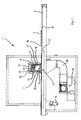
- Figure 1 shows an apparatus 1 for polymerisation of inks and paints on a support 2 comprising a conveyor 3 whereupon the support 2 rests.
- the conveyor 3 is movable through an operating zone 4 wherein drying of the support 2 occurs through the action of a beam of radiations emitted by a lamp 5 generating radiations, in particular ultraviolet radiations.
- the lamp 5 is partially surrounded by a concave reflector 6 that directs the reflected radiations towards the operating zone 4 underneath.
- a filter 7 is coupled that is suitable for substantially withholding the infrared radiations emitted by the lamp 5.
- the filter 7 comprises a top wall 8 and a bottom wall 9 that are parallel to one another and arranged at a preset distance from one another.
- the reflector 6 and the top wall 8 cooperate to define a chamber 11 within which the lamp 5 is contained.
- top wall 8 and the bottom wall 9 similarly delimit a chamber 21 within which coolant fluid is made to circulate, as will be disclosed in greater detail below.
- the aforementioned coolant fluid is suitable for removing heat generated by the portion of infrared radiation emitted by the lamp 5.
- the operating zone 4 is defined by a plane 12 whereupon a net 36 slides that is part of the conveyor 3, which has an end actuated by an electronically controlled motor 13.
- the plane 12 delimits at the top a seat 14 that is kept in a vacuum by suction means 15 that sucks the air contained therein by means of elbow-shaped suction conduits 16 communicating with the seat 14.
- the plane 12 is furthermore equipped with through holes that are not shown through which air is drawn inside the seat 14. This has two consequences: adhesion of the support 2 to the net 36 by means of a vacuum and cooling of the plane 12 through expansion of the air during passage through the aforementioned holes with consequent lowering of the temperature of the support 2 being processed.
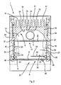
- Figures 2 to 5 show an apparatus 1 wherein the reflector 6 is defined by a profiled element 16, for example obtained through extrusion of an aluminium alloy.
- the profiled element 16 comprises a cavity 17 equipped with a concave wall 18 that identifies the reflecting surface 17 of the reflector 6.
- the profiled element 6 may be subjected to a polishing treatment, or be clad with a metallic layer, for example chrome, in order to improve the reflection of the radiation acting thereupon.
- the profiled element 16 comprises, inside the cavity 17, a first pair of grooves 19 and a second pair of grooves 20.
- the first pair of grooves 19 is suitable for receiving end 37 portions of the top wall 8 of the filter 7, whilst the second pair of grooves 20 is suitable for receiving end 38 portions of the bottom wall 9 of the filter 7.
- top wall 8 and the bottom wall 9 can be assembled, or replaced, very easily by positioning the top wall 8 and the bottom wall 9 at one of the sides of the apparatus 1 and exerting thereupon sufficient pressure to enable sliding of the aforementioned end portions within the respective grooves.
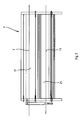
- the profiled element 16 comprises a plurality of appendages 22 protruding from a zone of the profiled element 16 adjacent to the concave wall 18, the appendage 22 constituting dissipating means 23 suitable for dissipating part of the heat generated by the lamp 5.
- conduits 31 are substantially parallel to one another, inside which a cooling fluid is made to flow.
- the appendages 22 act as heat exchangers enabling effective cooling of the lamp 5 and of the reflector 6.
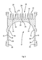
- the concave wall 18 comprises a projection 24 obtained in the top part thereof, the projection 24 being defined by a pair of faces 25 converging towards the zone of the cavity 17 wherein the lamp 5 is housed.
- the projection 24 acts as a deflecting element of the radiation inasmuch as the faces 25 are arranged in such a way that a beam of radiation produced by the lamp 5 and hitting the faces 25 is reflected towards a support 2 and not towards the lamp 5 itself, thus optimising the performance of the apparatus 1.
- the faces 25 thus constitute a pair of reflecting surfaces that prevent radiations from being again directed towards the lamp 5 by which they were produced, in such a way as to prevent overheating of the lamp itself.
- the portions of the profiled element 16 connected with the concave surface 18 and again comprised between the first pair of grooves 19 and the second pair of grooves 20 define side walls 10 of the chamber 21.
- Such side walls 10 comprise a plurality of lengths 26 diverging towards the operating zone 4 in such a way as to reflect the radiation towards the supports 2.
- the lengths 26 are mutually arranged in such a way as to give a saw-tooth profile to the side walls 10.
- Providing a plurality of lengths 26 furthermore enables the surface extension of the side walls 10 to be increased in relation to walls extending substantially along a plane, which improves heat exchange between the side walls 10 and the coolant fluid circulating within the chamber 21.
- the apparatus 1 furthermore comprises first fan means, not shown, arranged to induce the aforementioned coolant fluid to cross the chamber 21 in the direction shown by the arrow F in such a way as to create a flow of the aforementioned coolant fluid between a first delivery manifold 27 and a first collection manifold 28.
- the apparatus 1 furthermore comprises second fan means, which is also not shown, arranged to induce the aforementioned cooling fluid to go along the conduits 31 in the direction shown by the arrow F1 in such a way as to create a flow of the aforementioned cooling fluid between a second delivery manifold 29 and a second collection manifold 30.
- second fan means which is also not shown, arranged to induce the aforementioned cooling fluid to go along the conduits 31 in the direction shown by the arrow F1 in such a way as to create a flow of the aforementioned cooling fluid between a second delivery manifold 29 and a second collection manifold 30.
- the apparatus 1 furthermore comprises suction means, which is not shown, arranged to take ozone from the chamber 11, this ozone acting as a shielding element against ultraviolet radiation and thus penalising the efficiency of the lamp 5.
- Suction means generates a slight vacuum inside the chamber 11 that enables ozone to be extracted without, however, cooling the lamp 5.
- the apparatus 1 furthermore comprises shutter means 32 arranged to permit intermittent operation of the apparatus 1.
- Shutter means 32 comprises a pair of movable walls 33 that are arranged inside the chamber 21 and are movable between a closed position, indicated by A in Figure 2, wherein they intercept the radiation, and an open position, indicated by B in Figure 2, wherein they allow the radiation to reach the operating zone 4.
- the movable walls 33 similarly to the side walls 10, have a saw-tooth profile formed by further lengths 39 mutually arranged in such a way as to direct the radiation reflected thereby towards the operating zone 4, when the movable walls are in the open position B.
- the movable walls are transferred from the closed position A to the open position B, and vice versa, by means of a pair of actuators 34, each one of which is arranged to rotatingly actuate a lever 35 that is integral with a respective movable wall 33.
- Shutter means 32 enable intermittent operation of the apparatus without this making it necessary to switch off and subsequently switch on again the lamp 5.
- the lamp 5 is less subject to thermal stress caused by frequent switching off and switching on occurring within a short space of time of each other, which reduce the operating life of the lamp.
Landscapes
- Health & Medical Sciences (AREA)
- General Health & Medical Sciences (AREA)
- Toxicology (AREA)
- Engineering & Computer Science (AREA)
- Life Sciences & Earth Sciences (AREA)
- Microbiology (AREA)
- Mechanical Engineering (AREA)
- General Engineering & Computer Science (AREA)
- Physics & Mathematics (AREA)
- Electromagnetism (AREA)
- Physical Or Chemical Processes And Apparatus (AREA)
Applications Claiming Priority (2)
| Application Number | Priority Date | Filing Date | Title |
|---|---|---|---|
| ITMO20030095 | 2003-04-04 | ||
| IT000095A ITMO20030095A1 (it) | 2003-04-04 | 2003-04-04 | Apparato per la polimerizzazione di inchiostri e vernici su supporti |
Publications (2)
| Publication Number | Publication Date |
|---|---|
| EP1464679A2 true EP1464679A2 (de) | 2004-10-06 |
| EP1464679A3 EP1464679A3 (de) | 2007-09-05 |
Family
ID=29267034
Family Applications (1)
| Application Number | Title | Priority Date | Filing Date |
|---|---|---|---|
| EP04007775A Withdrawn EP1464679A3 (de) | 2003-04-04 | 2004-03-31 | Vorrichtung zur Polymerisation von Lacken und Tinten auf Trägern |
Country Status (2)
| Country | Link |
|---|---|
| EP (1) | EP1464679A3 (de) |
| IT (1) | ITMO20030095A1 (de) |
Cited By (3)
| Publication number | Priority date | Publication date | Assignee | Title |
|---|---|---|---|---|
| WO2008062277A3 (en) * | 2006-11-22 | 2009-02-12 | Viv Int Spa | Apparatuses and method for decorating objects |
| WO2010106332A1 (en) * | 2009-03-19 | 2010-09-23 | Gew (Ec) Limited | Improved housing for ink curing apparatus |
| EP2860035A1 (de) * | 2013-10-11 | 2015-04-15 | Seiko Epson Corporation | Flüssigkeitsausstossvorrichtung |
Family Cites Families (4)
| Publication number | Priority date | Publication date | Assignee | Title |
|---|---|---|---|---|
| GB9116120D0 (en) * | 1991-07-25 | 1991-09-11 | G E W Ec Ltd | U.v.dryers |
| GB2315850B (en) * | 1996-08-02 | 2000-10-04 | Spectral Technology Limited | Lamp assembly |
| DE19945074B4 (de) * | 1999-09-21 | 2007-01-18 | Printconcept Gmbh | Trocknungseinrichtung für beschichtete Substrate |
| DE50212070D1 (de) * | 2001-05-28 | 2008-05-21 | Barbara Gerstendoerfer-Hart | Vorrichtung zur erwärmung von substraten mit seitenblenden und sekundären reflektoren |
-
2003
- 2003-04-04 IT IT000095A patent/ITMO20030095A1/it unknown
-
2004
- 2004-03-31 EP EP04007775A patent/EP1464679A3/de not_active Withdrawn
Cited By (5)
| Publication number | Priority date | Publication date | Assignee | Title |
|---|---|---|---|---|
| WO2008062277A3 (en) * | 2006-11-22 | 2009-02-12 | Viv Int Spa | Apparatuses and method for decorating objects |
| US9340056B2 (en) | 2006-11-22 | 2016-05-17 | Decoral System Usa Corp. | Apparatuses and method for decorating objects |
| WO2010106332A1 (en) * | 2009-03-19 | 2010-09-23 | Gew (Ec) Limited | Improved housing for ink curing apparatus |
| EP2860035A1 (de) * | 2013-10-11 | 2015-04-15 | Seiko Epson Corporation | Flüssigkeitsausstossvorrichtung |
| US9352571B2 (en) | 2013-10-11 | 2016-05-31 | Seiko Epson Corporation | Liquid ejecting apparatus with a vapor collecting unit |
Also Published As
| Publication number | Publication date |
|---|---|
| ITMO20030095A1 (it) | 2004-10-05 |
| EP1464679A3 (de) | 2007-09-05 |
| ITMO20030095A0 (it) | 2003-04-04 |
Similar Documents
| Publication | Publication Date | Title |
|---|---|---|
| JP4992111B2 (ja) | 車両用灯具 | |
| EP0073669B1 (de) | Trockenvorrichtung | |
| JP6505677B2 (ja) | 内部偏向通気 | |
| US11987001B2 (en) | Machine for producing an additive printed part | |
| CN102016427A (zh) | 具有照明装置的烤箱和用于烤箱腔室的照明装置 | |
| CN107752793B (zh) | 具有马弗炉照明装置的家用烤箱 | |
| JP3750060B2 (ja) | ビルトイン電子レンジ | |
| US9797569B2 (en) | Headlight | |
| EP1464679A2 (de) | Vorrichtung zur Polymerisation von Lacken und Tinten auf Trägern | |
| CN111531890B (zh) | 聚合及调质装置 | |
| US6689991B2 (en) | Electronic range | |
| US4968871A (en) | Infra-red radiant heater with reflector and ventilated framework | |
| US5660543A (en) | Method and apparatus for enhanced convection brazing of aluminum assemblies | |
| US20030173348A1 (en) | Lightwave oven with cooling duct | |
| US12138859B2 (en) | Infrared radiation deflector and apparatus for the layer-by-layer formation of three-dimensional objects | |
| US8016407B2 (en) | Printer with an exposure head | |
| KR101723464B1 (ko) | 스트립 건조용 적외선 오븐 장치 | |
| KR20190080913A (ko) | 가변 열저항을 갖는 방열판 | |
| EP2026628B1 (de) | Vorrichtung zum Erwärmen einer Folie | |
| KR200232523Y1 (ko) | 전자레인지 캐비티의 흡배기 구조 | |
| CN1113190C (zh) | 加热烹调器 | |
| KR20020041252A (ko) | 후드겸용 전자레인지의 복사히터 냉각구조 | |
| KR0174963B1 (ko) | 광로 조절 장치용 덕트 | |
| CN1265129C (zh) | 微波炉的烤面包机散热装置 | |
| US20060044777A1 (en) | Spotlight |
Legal Events
| Date | Code | Title | Description |
|---|---|---|---|
| PUAI | Public reference made under article 153(3) epc to a published international application that has entered the european phase |
Free format text: ORIGINAL CODE: 0009012 |
|
| AK | Designated contracting states |
Kind code of ref document: A2 Designated state(s): AT BE BG CH CY CZ DE DK EE ES FI FR GB GR HU IE IT LI LU MC NL PL PT RO SE SI SK TR |
|
| AX | Request for extension of the european patent |
Extension state: AL LT LV MK |
|
| PUAL | Search report despatched |
Free format text: ORIGINAL CODE: 0009013 |
|
| AK | Designated contracting states |
Kind code of ref document: A3 Designated state(s): AT BE BG CH CY CZ DE DK EE ES FI FR GB GR HU IE IT LI LU MC NL PL PT RO SE SI SK TR |
|
| AX | Request for extension of the european patent |
Extension state: AL LT LV MK |
|
| 17P | Request for examination filed |
Effective date: 20080305 |
|
| AKX | Designation fees paid |
Designated state(s): AT BE BG CH CY CZ DE DK EE ES FI FR GB GR HU IE IT LI LU MC NL PL PT RO SE SI SK TR |
|
| 17Q | First examination report despatched |
Effective date: 20090708 |
|
| STAA | Information on the status of an ep patent application or granted ep patent |
Free format text: STATUS: THE APPLICATION IS DEEMED TO BE WITHDRAWN |
|
| 18D | Application deemed to be withdrawn |
Effective date: 20111001 |