EP1464497A1 - Pump wetting in a liquid ejecting apparatus - Google Patents
Pump wetting in a liquid ejecting apparatus Download PDFInfo
- Publication number
- EP1464497A1 EP1464497A1 EP04007803A EP04007803A EP1464497A1 EP 1464497 A1 EP1464497 A1 EP 1464497A1 EP 04007803 A EP04007803 A EP 04007803A EP 04007803 A EP04007803 A EP 04007803A EP 1464497 A1 EP1464497 A1 EP 1464497A1
- Authority
- EP
- European Patent Office
- Prior art keywords
- positive displacement
- state
- displacement pump
- standard
- pump
- Prior art date
- Legal status (The legal status is an assumption and is not a legal conclusion. Google has not performed a legal analysis and makes no representation as to the accuracy of the status listed.)
- Granted
Links
- 239000007788 liquid Substances 0.000 title claims abstract description 99
- 238000009736 wetting Methods 0.000 title claims abstract description 59
- 238000006073 displacement reaction Methods 0.000 claims abstract description 250
- 239000000080 wetting agent Substances 0.000 claims description 77
- 230000037452 priming Effects 0.000 claims description 65
- 238000000034 method Methods 0.000 claims description 11
- 230000007246 mechanism Effects 0.000 description 34
- 238000007599 discharging Methods 0.000 description 26
- 238000012423 maintenance Methods 0.000 description 21
- 230000006870 function Effects 0.000 description 18
- 238000007641 inkjet printing Methods 0.000 description 18
- 238000007639 printing Methods 0.000 description 17
- 230000008859 change Effects 0.000 description 16
- 238000011010 flushing procedure Methods 0.000 description 16
- 238000010586 diagram Methods 0.000 description 7
- 238000003860 storage Methods 0.000 description 6
- 230000009471 action Effects 0.000 description 4
- 238000012856 packing Methods 0.000 description 4
- 230000005499 meniscus Effects 0.000 description 3
- 230000001133 acceleration Effects 0.000 description 2
- 230000008602 contraction Effects 0.000 description 2
- 238000005530 etching Methods 0.000 description 2
- 230000008569 process Effects 0.000 description 2
- 238000005096 rolling process Methods 0.000 description 2
- 229920006269 PPS film Polymers 0.000 description 1
- XUIMIQQOPSSXEZ-UHFFFAOYSA-N Silicon Chemical compound [Si] XUIMIQQOPSSXEZ-UHFFFAOYSA-N 0.000 description 1
- 241000610628 Trichoptilium incisum Species 0.000 description 1
- 239000003795 chemical substances by application Substances 0.000 description 1
- 238000013461 design Methods 0.000 description 1
- 230000000694 effects Effects 0.000 description 1
- 239000013013 elastic material Substances 0.000 description 1
- 239000003292 glue Substances 0.000 description 1
- 229910001338 liquidmetal Inorganic materials 0.000 description 1
- 238000004519 manufacturing process Methods 0.000 description 1
- 239000000463 material Substances 0.000 description 1
- 238000005192 partition Methods 0.000 description 1
- 239000011295 pitch Substances 0.000 description 1
- 229920006254 polymer film Polymers 0.000 description 1
- 238000012545 processing Methods 0.000 description 1
- 229910052710 silicon Inorganic materials 0.000 description 1
- 239000010703 silicon Substances 0.000 description 1
- 239000002904 solvent Substances 0.000 description 1
- 238000012546 transfer Methods 0.000 description 1
Images






Classifications
-
- B—PERFORMING OPERATIONS; TRANSPORTING
- B41—PRINTING; LINING MACHINES; TYPEWRITERS; STAMPS
- B41J—TYPEWRITERS; SELECTIVE PRINTING MECHANISMS, i.e. MECHANISMS PRINTING OTHERWISE THAN FROM A FORME; CORRECTION OF TYPOGRAPHICAL ERRORS
- B41J2/00—Typewriters or selective printing mechanisms characterised by the printing or marking process for which they are designed
- B41J2/005—Typewriters or selective printing mechanisms characterised by the printing or marking process for which they are designed characterised by bringing liquid or particles selectively into contact with a printing material
- B41J2/01—Ink jet
- B41J2/135—Nozzles
- B41J2/165—Prevention or detection of nozzle clogging, e.g. cleaning, capping or moistening for nozzles
- B41J2/16517—Cleaning of print head nozzles
- B41J2/1652—Cleaning of print head nozzles by driving a fluid through the nozzles to the outside thereof, e.g. by applying pressure to the inside or vacuum at the outside of the print head
- B41J2/16532—Cleaning of print head nozzles by driving a fluid through the nozzles to the outside thereof, e.g. by applying pressure to the inside or vacuum at the outside of the print head by applying vacuum only
Definitions
- This invention relates to a liquid ejecting apparatus having a head member capable of ejecting a drop of liquid from a nozzle.
- an ink-jetting recording apparatus which is an example of liquid ejecting apparatus, includes a recording head having a nozzle, an ink-jetting means for ejecting ink from the nozzles (for example, a piezoelectric vibrating member or a heat-generating member), and a main controlling part that controls the ink-jetting means based on recording data.
- a recording head having a nozzle
- an ink-jetting means for ejecting ink from the nozzles for example, a piezoelectric vibrating member or a heat-generating member
- main controlling part that controls the ink-jetting means based on recording data.
- the nozzle of the recording head may be clogged with thickened ink.
- the thickened ink may be forcibly sucked, from the nozzle.
- Tube pumps are commonly used for forcibly sucking the thickened ink.
- a tube In a tube pump, a tube is collapsed by a pulley, and then returns to an original shape of the tube due to rigidity thereof. The latter volume change provides a suction power.
- the rigidity of the tube may change depending on temperature change or the like, so that suction speed may also change undesirably.
- suction speed may also change undesirably.
- it is effective to raise a rotation speed of the pulley.
- the pulley is rotated at a speed faster than that at which the collapsed tube returns to the original shape. That is, the volume of sucked ink can not be increased greatly.
- the diameter of the tune is increased, the volume of sucked ink maybe increased.
- the thickness of the tube has to be increased in order to maintain the rigidity of the tube, which results in the larger sucking system.
- the inventor has paid attention to a built-in slide-rotator type of positive displacement pump, because it is easy to downsize and optimally design the built-in slide-rotator type of positive displacement pump depending on a driving rotational speed and/or a required flow rate.
- JP Laid-Open Publication No. 55-64178 discloses a technique wherein a wetting agent is injected from outside into between a seal ring and a seal plate before driving a gear pump (an example of built-in slide-rotator type of positive displacement pump) , when a kind of heated liquid is conveyed by the gear pump.
- a gear pump an example of built-in slide-rotator type of positive displacement pump
- the object of this invention is to solve the above problems, thatis, to provide a liquid ejecting apparatus includingabuilt-in slide-rotator type of positive displacement pump wherein the inside of the positive displacement pump can be efficiently returned from a dry state to a wet state.
- the "wet state" in the inside of the positive displacement pump means a state capable of providing a negative pressure equal to or greater than -5 kPa, preferably -15 kPa, by means of an operation of the positive displacement pump.
- the invention is a liquid ejecting apparatus comprising: a head member having a nozzle and a liquid-ejecting unit that ejects liquid in the nozzle; a main controlling part that drives the liquid-ejecting unit based on ejecting data; a capping member relatively movable between a position away from the head member and a position in contact with the head member; a suction way communicated with an inside of the capping member; a built-in slide-rotator type of positive displacement pump provided in the suction way; a state-quantity recognizing part that recognizes a state quantity related to a dry state in an inside of the built-in slide-rotator type of positive displacement pump; a standard-state-quantity setting part in which a standard state quantity is set, the standard state quantity being a standard for carrying out a preliminary operation for wetting the inside of the positive displacement pump; a judging part that judges whether the inside of the positive displacement pump is dry or not, by comparing the state quantity recognized by the state
- the inside of the positive displacement pump can be efficiently returned from a dry state to a wet state.
- the invention is a liquid ejecting apparatus comprising: a head member having a nozzle and a liquid-ejecting unit that ejects liquid in the nozzle; a main controlling part that drives the liquid-ejecting unit based on ejecting data; a capping member relatively movable between a position away from the head member and a position in contact with the head member; a suction way communicated with an inside of the capping member; a built-in slide-rotator type of positive displacement pump provided in the suction way; a state-quantity recognizing part that recognizes a state quantity related to a dry state in an inside of the built-in slide-rotator type of positive displacement pump; a standard-state-quantity setting part in which a standard state quantity is set, the standard state quantity being a standard for carrying out a preliminary operation for wetting the inside of the positive displacement pump; a judging part that judges whether the inside of the positive displacement pump is dry or not, by comparing the state quantity recognized by the state-quantity
- the judge result is displayed by the displaying unit, so that an operator (user) can estimate or notice a dry state in the inside of the positive displacement pump. This makes it possible to efficiently carry out the preliminaryoperation for wetting the inside of thepositive displacement pump.
- the preliminary-operation carrying-out part is adapted to cause the liquid-ejecting unit to eject liquid from the nozzle into the capping member, and thereafter drive the built-in slide-rotator type of positive displacement pump for a predetermined preliminary-operation time.
- thebuilt-in slide-rotator type of positive displacement pump is efficiently returned to a wet state.
- it is unnecessary to prepare a special wetting agent.
- it is unnecessary to provide another mechanism for introducing a wetting agent, that is, the structure is simpler.
- thebuilt-in slide-rotator type of positive displacement pump may have a pump frame connected to the suction way, and a wetting-agent supplying way for supplying a wetting agent may be connected to the pump frame.
- the preliminary-operation carrying-out part is adapted to supply the wetting agent into the pump frame via the wetting-agent supplying way.
- an optimumwetting agent can be supplied at an optimum flow rate.
- the preliminary-operation carrying-out part is adapted to supply the wetting agent into the pump frame by causing the priming pump to operate.
- the head member is integrated with a pushing member, and the pushing member is movable in a direction in such a manner that the pushing member can push the priming pump to cause the priming pump to operate
- the preliminary-operation carrying-out part is adapted to supply the wetting agent into the pump frame by causing the priming pump to operate via the pushing member by moving the head member.
- the invention is a liquid ejecting apparatus comprising: a head member having a nozzle and a liquid-ejecting unit that ejects liquid in the nozzle; a main controlling part that drives the liquid-ejecting unit based on ejecting data; a capping member relatively movable between a position away from the head member and a position in contact with the head member; a suction way communicated with an inside of the capping member; a built-in slide-rotator type of positive displacement pump provided in the suction way; a state-quantity recognizing part that recognizes a state quantity related to a dry state in an inside of the built-in slide-rotator type of positive displacement pump; a standard-state-quantity setting part in which a standard state quantity is set, the standard state quantity being a standard for carrying out a preliminary operation for wetting the inside of the positive displacement pump; a judging part that judges whether the inside of the positive displacement pump is dry or not, by comparing the state quantity recognized by the state-quantity
- the judge result is displayed by the displaying unit, so that an operator (user) can estimate or notice a dry state in the inside of the positive displacement pump. This makes it possible to efficiently cause the priming pump to operate for wetting the inside of the positive displacement pump.
- the state quantity related to a dry state in an inside of the built-in slide-rotator type of positive displacement pump is a non-operating time of the positive displacement pump.
- the state-quantity recognizing part is a non-operating-time recognizing part that recognizes the non-operating time
- the standard state quantity being a standard for carrying out a preliminary operation is a standard time being a standard for carrying out a preliminary operation
- the standard-state-quantity setting part is a standard-time setting part in which the standard time is set
- the judging part is adapted to judge that the insideof the positive displacement pump is dry, when the non-operating time recognized by the non-operating-time recognizing part is equal to or longer than the standard time set in the standard-time setting part.
- the state quantity related to a dry state in an inside of the built-in slide-rotator type of positive displacement pump may be a continuous open time of the capping member or an elapsed time in an OFF state of an electric power source.
- the state quantity related to a dry state in an inside of the built-in slide-rotator type of positive displacement pump may be a state quantity related to an operating state of the positive displacement pump after the positive displacement pump has been driven for a predetermined time.
- the state quantity related to an operating state of the positive displacement pump is a pressure in the capping member after the positive displacement pump has been driven for a predetermined time. If the pressure in the capping member after the positive displacement pump has been driven for a predetermined time doesn' t reach a predetermined negative pressure, it can be estimated that the inside of the positive displacement pump is in a dry state.
- the state-quantity recognizing part is a pressure detecting part that recognizes the pressure in the capping member
- the standard state quantity being a standard for carrying out a preliminary operation is a standard negative pressure being a standard for carrying out a preliminary operation
- the standard-state-quantity setting part is a standard-negative-pressure setting part in which the standard negative pressure is set
- the judging part is adapted to judge that the inside of the positive displacement pump is dry, when the pressure in the capping member recognized by the pressure detecting part is equal to or above the standard negative pressure set in the standard-negative-pressure setting part.
- a film sensor or the like provided in a liquid way may be used as the pressure detecting part.
- the state quantity related to an operating state of the positive displacement pump may be a state quantity related to a liquid flow after the positive displacement pump has been driven for a predetermined time. If an expected liquid flow isn' t generated after the positive displacement pump has been driven for a predetermined time, it can be estimated that the inside of the positive displacement pump is in a dry state.
- the state quantity related to a liquid flow may be detected by a photon-interrupter provided in a liquid way, or an electrode provided in the capping member or the positive displacement pump, or the like.
- a liquid flow into the pump may be detected, by detecting change in a rotational load of a motor for driving the pump from an electrical current waveform of the motor.
- the built-in slide-rotator type of positive displacement pump means any pump including: a casing member, at least one rotator consisting of one or more parts, and a power transfer device for rotating the rotator, wherein a pump action is achieved by volume change caused by rotation of the rotator in the casing member.
- the built-in slide-rotator type of positive displacement pump may be any gear pump, any roots pump, any quimby screw pump, any vane pump, or the like.
- the concept of the present invention can be also applied to cases using a reciprocating-mechanism type of positive displacement pump instead of the built-in slide-rotator type of positive displacement pump.
- the invention is a liquid ejecting apparatus comprising: a head member having a nozzle and a liquid-ejecting unit that ej ects liquid in the nozzle; a main controlling part that drives the liquid-ejecting unit based on ejecting data; a capping member relatively movable between a position away from the head member and a position in contact with the head member; a suction way communicated with an inside of the capping member; a reciprocating-mechanism type of positive displacement pump provided in the suction way; a state-quantity recognizing part that recognizes a state quantity related to a dry state in an inside of the reciprocating-mechanism type of positive displacement pump; a standard-state-quantity setting part in which a standard state quantity is set, the standard state quantity being a standard for carrying out a
- the inside of the positive displacement pump can be efficiently returned from a dry state to a wet state.
- the invention is a liquid ejecting apparatus comprising: a head member having a nozzle and a liquid-ejecting unit that ejects liquid in the nozzle; a main controlling part that drives the liquid-ejecting unit based on ejecting data; a capping member relatively movable between a position away from the head member and a position in contact with the head member; a suction way communicated with an inside of the capping member; a reciprocating-mechanism type of positive displacement pump provided in the suction way; a state-quantity recognizing part that recognizes a state quantity related to a dry state in an inside of the reciprocating-mechanism type of positive displacement pump ; a standard-state-quantity setting part in which a standard state quantity is set, the standard state quantity being a standard for carrying out a preliminary operation for wetting the inside of the positive displacement pump; a judging part that judges whether the inside of the positive displacement pump is dry or not, by comparing the state quantity recognized by the state-quantity recognizing
- the judge result is displayed by the displaying unit, so that an operator (user) can estimate or notice a dry state in the inside of the positive displacement pump. This makes it possible to efficiently carry out the preliminary operation for wetting the insideof the positive displacement pump.
- the preliminary-operation carrying-out part is adapted to cause the liquid-ejecting unit to eject liquid from the nozzle into the capping member, and thereafter drive the reciprocating-mechanism type of positive displacement pump for a predetermined preliminary-operation time.
- the reciprocating-mechanism type of positive displacement pump is efficiently returned to a wet state.
- it is unnecessary to prepare a special wetting agent.
- it is unnecessary to provide another mechanism for introducing a wetting agent, that is, the structure is simpler.
- the reciprocating-mechanism type of positive displacement pump may have a pump frame connected to the suction way, and a wetting-agent supplying way for supplying a wetting agent may be connected to the pump frame.
- the preliminary-operation carrying-out part is adapted to supply the wetting agent into the pump frame via the wetting-agent supplying way.
- an optimum wetting agent can be supplied at an optimum flow rate.
- the preliminary-operation carrying-out part is adapted to supply the wetting agent into the pump frame by causing the priming pump to operate.
- the head member is integrated with a pushing member, and the pushing member is movable in a direction in such a manner that the pushing member can push the priming pump to cause the priming pump to operate
- the preliminary-operation carrying-out part is adapted to supply the wetting agent into the pump frame by causing the priming pump to operate via the pushing member by moving the head member.
- the invention is a liquid ejecting apparatus comprising: a head member having a nozzle and a liquid-ejecting unit that ejects liquid in the nozzle; a main controlling part that drives the liquid-ejecting unit based on ejecting data; a capping member relatively movable between a position away from the head member and a position in contact with the head member; a suction way communicated with an inside of the capping member; a reoiprocating-mechanism type of positive displacement pump provided in the suction way; a state-quantity recognizing part that recognizes a state quantity related to a dry state in an inside of the reciprocating-mechanism type of positive displacement pump; a standard-state-quantity setting part in which a standard state quantity is set, the standard state quantity being a standard for carrying out a preliminary operation for wetting the inside of the positive displacement pump; a judging part that judges whether the inside of the positive displacement pump is dry or not, by comparing the state quantity recognized by the state-
- the judge result is displayed by the displaying unit, so that an operator (user) can estimate or notice a dry state in the inside of the positive displacement pump. This makes it possible to efficiently cause the priming pump to operate for wetting the inside of the positive displacement pump.
- the state quantity related to a dry state in an inside of the reciprocating-mechanism type of positive displacement pump is a non-operating time of the positive displacement pump.
- the state quantity related to a dry state in an inside of the reciprocating-mechanism type of positive displacement pump may be a continuous open time of the capping member or an elapsed time in an OFF state of an electric power source.
- the state quantity related to a dry state in an inside of the reciprocating-mechanism type of positive displacement pump may be a state quantity related to an operating state of the positive displacement pump after the positive displacement pump has been driven for a predetermined time.
- the reciprocating-mechanism type of positive displacement pump may be any piston pump, any bellows pump, any diaphragm pump, or the like.
- the invention is a controlling unit for controlling a liquid ejecting apparatus including: a head member having a nozzle and a liquid-ejecting unit that ejects liquid in the nozzle; a main controlling part that drives the liquid-ejecting unit based on ejecting data; a capping member relatively movable between a position away from the head member and a position in contact with the head member; a suction way communicated with an inside of the capping member; and a built-in slide-rotator type of positive displacement pump provided in the suction way; the controlling unit comprising a state-quantity recognizing part that recognizes a state quantity related to a dry state in an inside of the built-in slide-rotator type of positive displacement pump, a standard-state-quanti ty setting part in which a standard state quantity is set, the standard state quantitybeing a standard for carrying out a preliminary operation for wetting the inside of the positive displacement pump, a judging part that judges whether the inside of thepositive displacement pump is dry or not,
- the invention is a controlling unit for controlling a liquid ejecting apparatus including: a head member having a nozzle and a liquid-ejecting unit that ejects liquid in the nozzle; a main controlling part that drives the liquid-ejecting unit based on ejecting data; a capping member relatively movable between a position away from the head member and a position in contact with the head member; a suction way communicated with an inside of the capping member; and a reciprocating-mechanism type of positive displacement pump provided in the suction way; the controlling unit comprising a state-quantity recognizing part that recognizes a state quantity related to a dry state in an inside of the reciprocating-mechanism type of positive displacement pump, a standard-state-quantity setting part in which a standard state quantity is set, the standard state quantitybeing a standard for carrying out a preliminary operation for wetting the inside of the positive displacement pump, a judging part that judges whether the inside of thepositive displacement pump is dry or not, by comparing the state
- a computer system can materialize the controlling units or any element of the above controlling units.
- This invention includes a storage unit capable of being read by a computer, storing a program for materializing the controlling unit or the element in a computer system.
- This invention also includes the program itself for materializing the controlling unit or the element in the computer system.
- This invention includes a storage unit capable of being read by a computer, storing a program including a command for controlling a second program executed by a computer system including a computer, the program being executed by the computer system to control the second program to materialize the controlling unit or the element.
- This invention also includes the program itself including the command for controlling the second program executed by the computer system including the computer, the program being executed by the computer system to control the second program to materialize the controlling unit.
- the storage unit may be not only a substantial object such as a floppy disk or the like, but also a network for transmitting various signals.
- the invention is a method of controlling a liquid ejecting apparatus including: a head member having a nozzle and a liquid-ejecting unit that ejects liquid in the nozzle; a main controlling part that drives the liquid-ejecting unit based on ejecting data; a capping member relatively movable between a position away from the head member and a position in contact with the head member; a suction way communicated with an inside of the capping member; and a built-in slide-rotator type of positive displacement pump provided in the suction way; the method comprising a step of recognizing a state quantity related to a dry state in an inside of the built-in slide-rotator type of positive displacement pump, a step of judging whether the inside of the positive displacement pump is dry or not, by comparing the state quantity related to a dry state in an inside of the built-in slide-rotator type of positive displacement pump with a standard state quantity that has been set in advance, and a step of carrying out a preliminary operation for wetting the inside
- the invention is a method of controlling a liquid ejecting apparatus including: a head member having a nozzle anda liquid-ejecting unit that ejects liquidin the nozzle; a main controlling part that drives the liquid-ejecting unit based on ejecting data; a capping member relatively movable between a position away from the head member and a position in contact with the head member; a suction way communicated with an inside of the capping member; and a reciprocating-mechanism type of positive displacement pump provided in the suction way; the method comprising a step of recognizing a state quantity related to a dry state in an inside of the reciprocating-mechanism type of positive displacement pump, a step of judging whether the inside of the positive displacement pump is dry or not, by comparing the state quantity related to a dry state in an inside of the reciprocating-mechanism type of positive displacement pump with a standard state quantity that has been set in advance, and a step of carrying out a preliminary operation for wetting the inside of the positive displacement
- Fig. 1 is a schematic perspective view of an ink-jetting printer 1 as a liquid ejecting apparatus of a first embodiment according to the invention.
- the ink-jetting printer 1 includes a carriage 5 supporting a recording head 4 (head member) that has a cartridge holder 4a capable of holding an ink cartridge 2 (liquid container).
- the carriage 5 is adapted to be reciprocated in a main scanning direction by a head-scanning mechanism.
- the head-scanning mechanism is formed by: a guide bar 6 horizontally extending in a housing, a pulse motor 7 arranged at a right portion of the housing, a driving pulley 8 connected to a rotational shaft of the pulse motor 7, a free pulley 9 mounted at a left portion of the housing, a timing belt 10 connected to the carriage 5 and going around the driving pulley 8 and the free pulley 9, and a controller 11 (see Fig. 6) for controlling the pulse motor 7.
- the carriage 5 i.e. the recording head 4 can be reciprocated in the main scanning direction i.e. in a width direction of a recording paper 12, by driving the pulse motor 7.
- the printer 1 includes a paper feeding mechanism for feeding the recording paper 12 or any other recording medium (a medium onto which the ink (liquid) is jetted (ejected)) in a feeding direction (sub-scanning direction).
- the paper feeding mechanism consists of a paper feeding motor 13, a paper feeding roller 14 or the like.
- the recording paper 12, which is an example of a recording medium, is fed in a subordinate scanning direction in turn by the paper feeding mechanism, in cooperation with the recording operation of the recording head 4.
- the printer 1 is adapted to conduct a recording operation when the recording head 4 is moved forth (single-direction recording).
- a home position and a waiting position of the recording head 4 are set in a scanning range of the carriage 5 and in an end area outside an objective recording area.
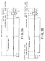
- the home position is set at an end portion (a right end portion in Fig. 2A) in the scanning range of the recording head 4.
- the waiting position is set substantially adjacently to the home position on a side of the objective recording area.
- a second waiting position WP2 may be set at an opposite end portion with respect to a home position, in addition to a first waiting position WP1 substantially adjacent to the home position.
- the home position is a position that the recording head 4 is moved to and stays at when electric power supply is off or when a long time has passed since the last recording operation.
- a capping member 15 of the capping mechanism comes in contact with a nozzle plate 16 (see Fig. 6) and substantially seals nozzles 17 (see Fig. 6) , which is described below in detail.
- the capping member 15 is a tray-like member having a substantially square shape, being open upward, and made of an elastic material such as a rubber. A moisture retaining material such as felt is attached inside the capping member 15.
- an inside of the capping member 15 is kept in high humid condition. Thus, it can be prevented that solvent of the ink evaporates from the nozzles 17.
- the waiting position is a starting position for moving the recording head 4 in the main scanning direction. That is, normally, the recording head 4 stays and waits at the waiting position.
- the recording head 4 is moved from the waiting position to the objective recording area. Then, when the recording operation is completed, the recording head 4 is moved back to the waiting position.
- the recording head 4 is moved forth from the first waiting position WP1 to the second waiting position WP2 through the objective recording area, while jetting one or more drops of ink to the objective recording area. After that, the recording head 4 stays and waits at the second waiting position WP2. Then, the recording head 4 is moved back from the second waiting position WP2 to the first waiting position WP1 through the objective recording area, while jetting one or more drops of ink to the objective recording area. After that, the recording head 4 stays and waits at the first waiting position WP1. After that, the recording operation during moved forth and the recording operation during moved back are repeated in turn.
- An ink-receiving member may be arranged under the waiting position in order to collect ink discharged from the recording head 4 because of flushing operations (maintenance operations).
- the capping member 15 functions as such an ink-receiving member. That is, as shown in Fig. 3A, the capping member 15 is usually located ata position under the wai tingposition of the recording head 4 (a little apart from the nozzle plate 16). Then, when the recording head 4 is moved to the home position, as shown in Fig. 3D, the capping member 15 is also moved diagonally upward to the home position and to the nozzle plate 16 in order to seal the nozzles 17.
- a second ink-receiving member 18 may be arranged under the second waiting position WP2.
- the second ink-receiving member 18 may be a flushing box open upward i.e. toward the recording head 4.
- an acceleration area is set between the waiting position and the objective recording area.
- the acceleration area is an area for raising a scanning velocity of the recording head 4 to a predetermined velocity.
- a suction way 15w is extended from the capping member 15 of the embodiment.
- the suction way is communicated with the inside of the capping member 15.
- a gear pump 15g which is a built-in slide-rotator type of positive displacement pump, is provided on the way of the suction way 15w.
- the gear pump 15g is formed in such a precise manner that a gap between a gear and a pump frame (casing) is not more than 100 micron in both a radial direction and a thickness direction.
- Fig. 5A is a perspective view of the gear pump 15g
- Fig. 5B is an exploded view of the gear pump 15g
- Fig. 5C is a partial sectional view of the gear pump 15.
- the gear pump 15g includes: a pump frame (casing) 151 having a suction port 151a connected to the suction way 15w; and a driving gear 152 and a driven gear 153 that are engaged with each other and slidably contained in the pump frame 151 with the above precision (via liquid (ink) menisci).
- the driving gear 152 is rotated by means of a driving gear shaft 154 that pierces the pump frame 151 and/or a lid 157.
- the driven gear 153 is pivotally supported by the pump frame 151 and the lid 157 via a driven gear shaft 155 that is parallel to the driving gear shaft 154.
- the pump frame (casing) 151 is sealed by the lid 157 via a packing 156.
- the lid 157 has a discharging port 157a.
- the suction port 151a and the discharging port 157a are located opposite with respect to'a slide area between the gears 152, 153 and the pump frame 151.
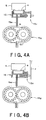
- the capping member 15 of the embodiment has a release-valve mechanism 15v that is normally open.
- the release-valve mechanism 15v has a small diameter.
- the release-valve mechanism 15v is adapted to close only when the capping member 15 comes in contact with a frame F or the like, correspondingly to when it is necessary to suck the ink.
- the inside of the capping member 15 is normally communicated with the atmosphere, so that it is prevented the menisci are broken down by temperature change or the like, while the capping member 15 is suitably sealed when the ink has to be sucked.
- the recording head 4 has: a black head unit capable of jetting a drop of black ink, a cyan head unit capable of jetting a drop of cyan ink, a magenta head unit capable of jetting a drop of magenta ink, a yellow head unit capable of jetting a drop of yellow ink, a light cyan head unit capable of jetting a drop of light cyan ink, and a light magenta head unit capable of jetting a drop of light magenta ink.
- Each head unit has a bottom surface on which the nozzles 17 are formed in the sub-scanning direction. The number of the nozzles 17 for each head unit is common, so that the nozzles 17 of the respective head units are also aligned in the main scanning direction.
- the head units in the embodiment have substantially the same structure.
- the head unit has a plastic box-like case 71 defining a housing room 72.
- the longitudinal-mode piezoelectric vibrating unit 21 has a shape of teeth of a comb, and is inserted in the housing room 72 in such a manner that points of teeth-like portions 21a of the piezoelectric vibrating unit 21 are aligned at an opening of the housing room 72.
- a ink-way unit 74 is bonded on a surface of the case 71 on the side of the opening of the housing room 72.
- the points of the teeth-like portions 21a are fixed at predetermined positions of the ink-way unit 74 to function as piezoelectric vibrating members respectively.
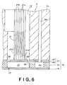
- the piezoelectric vibrating unit 21 comprises a plurality of piezoelectric layers 21b. As shown in Fig. 6, common inside electrodes 21c and individual inside electrodes 21d are inserted alternately between each adjacent two of the piezoelectric layers 21b. The piezoelectric layers 21b, the common inside electrodes 21c and the individual inside electrodes 21d are integrated and cut into the shape of the teeth of the comb. Thus, when a voltage is provided between the common inside electrodes 21c and an individual inside electrode 21d, a piezoelectric vibrating member contracts in a longitudinal direction of each of the piezoelectric layers 21b,
- the ink-way unit 74 consists of a nozzle plate 16, an elastic plate 77 and an ink-way forming plate 75 sandwiched between the nozzle plate 16 and the elastic plate 77.
- the nozzle plate 16, the ink-way forming plate 75 and the elastic plate 77 are integrated as shown in Fig. 6.
- a plurality of nozzles 17 is formed in the nozzle plate 16.
- a plurality of pressure generating chambers 22, a plurality of supplying ways 82 and a common chamber 83 are formed in the ink-way forming plate 75.
- Each of the pressure chambers 22 is defined by partition walls, and is communicated with a corresponding nozzle 17 at an end portion thereof and with a corresponding supplying way 82 at the other end portion thereof.
- the common chamber 83 is communicated with all the supplying ways 82, and has a longitudinal shape.
- the longitudinal common chamber 83 may be formed by an etching process when the ink-way forming plate 75 is a silicon wafer.
- the pressure chambers 22 are formed in the longitudinal direction of the common chamber 83 at the same intervals (pitches) as nozzles 17. Then, a groove as an supplying way 82 is formed between each of the pressure chambers 22 and the common chamber 83.
- the supplying way 82 is connected to an end of the pressure chamber 22, while the nozzle 17 is located near the other end of the pressure chamber 22.
- the common chamber 83 is adapted to supply ink saved in the ink cartridge 2 to the pressure chambers 22.
- An supplying tube 84 from the ink cartridge is communicated with a middle portion of the common chamber 83.
- the elastic plate 77 is layered on a surface of the ink-way forming plate 75 opposed to the nozzle plate 16.
- the elastic plate 77 consists of two laminated layers that are a stainless plate 87 and an elastic high-polymer film 88 such as a PPS film.
- the stainless plate 87 is provided with island portions 89 for fixing the teeth-like portions 21a as the piezoelectric vibrating members 21 in respective portions corresponding to the pressure chambers 22, by an etching process.
- a tooth-like portion 21a as a piezoelectric vibrating member can expand in the longitudinal direction. Then, an island portion 89 is pressed toward the nozzle plate 16, the elastic film 88 is deformed. Thus, a corresponding pressure chamber 22 contracts.
- the tooth-like portion 21a as the piezoelectric vibrating member can contract from the expanding state in the longitudinal direction. Then, the elastic film 88 is returned to the original state owing to elasticity thereof. Thus, the corresponding pressure chamber 22 expands. By causing the pressure chamber 22 to expand and then causing the pressure chamber 22 to contract, a pressure of the ink in the pressure chamber 22 increases so that the ink drop is jetted from a nozzle 17.
- the volume of the corresponding pressure chamber 22 is also changed.
- the pressure of the ink in the pressure chamber 22 can be changed, so that a drop of the ink can be jetted from the corresponding nozzle 17 or a meniscus at the corresponding nozzle 17 can be minutely vibrated.
- the meniscus means a free surface of the ink exposed at an opening of the nozzle 17.
- bending-mode piezoelectric vibrating members can be used.
- a charging operation causes apressure chamber to contract
- a discharging operation causes the pressure chamber to expand.
- the ink-jetting printer 1 has a printer controller 30 and a printing engine 31.
- the printer controller 30 has: an outside interface (outside I/F) 32, a RAM 33 which is able to temporarily store various data, a ROM 34 which stores a controlling program or the like, a controlling part 11 including CPU or the like, an oscillating circuit 35 for generating a clock signal, an driving-signal generating part 36 for generating an driving signal that is supplied into each head unit of the recording head 4, and an inside interface (inside I/F) 37 that is adapted to send the driving signal, dot-pattern-data (bit-map-data) developed according to printing data (jetting data) or the like to the print engine 31.
- the outside I/F 32 is adapted to receive printing data consisting of character codes, graphic functions, image data or the like from a host computer not shown or the like.
- a busy signal (BUSY) or an acknowledge signal (ACK) is adapted to be outputted to the host computer or the like through the outside I/F 32.
- the outside I/F32 in the embodiment is connected to an interface unit 100 such as a keyboard, which may function as an input part into which information of dense-thin desire of a user about a "fully-covering" control may be inputted by the user.
- an interface unit 100 such as a keyboard
- the RAM 33 has a receiving buffer, an intermediate buffer, an outputting buffer and a work memory not shown.
- the receiving buffer is adapted to receive the printing data through the outside 1/F 32, and temporarily store the printing data.
- the intermediate buffer is adapted to store intermediate-code-data converted from the printing data by the controlling part 11.
- the outputting buffer is adapted to store dot-pattern-data which are data for printing obtained by decoding (translating) the intermediate-code-data (for example, level data).
- the ROM 34 stores font data, graphic functions or the like in addition to the controlling program (controlling routine) for carrying out various data-processing operations.
- the ROM 34 also stores various setting data for maintenance operations.
- the controlling part 11 is adapted to carry out various controllingoperations according to the controllingprogramstored in the ROM 34. For example, the controlling part 11 reads out the printing data from the receiving buffer, converts the printing data into the intermediate-code-data, and causes the intermediate buffer to store the intermediate-code-data. Then, the controlling part 11 analyzes the intermediate-code-data in the intermediate buffer and develops (decodes) the intermediate-code-data into the dot-pattern-data with reference to the font data and the graphic functions or the like stored in the ROM 34. Then, the controlling part 11 carries out necessary decorating operations to the dot-pattern-data, and thereafter causes the outputting buffer to store the dot-pattern-data.
- the dot-pattern-data corresponding to one line recorded by one main scanning of the recording head 4 are obtained, the dot-pattern-data are outputted to an electric driving system 39 of each head unit of the recording head 4 from the outputting buffer through the inside I/F 37 in turn. Then, the carriage 5 is moved in the main scanning direction, that is, the recording operation for the one line is conducted.
- the dot-pattern-data corresponding to the one line are outputted from the outputting buffer, the intermediate-code-data that has been developed are deleted from the intermediate buffer, and the next developing operation starts for the next intermediate-code-data.
- controlling part 11 is adapted to control a maintenance operation (a recovering operation) conducted separately from the recording operation by the recording head 4.
- controlling part 11 is also adapted to control a preliminary operation for wetting the inside of the gear pump 15g. That is, the controlling part 11 is connected to the gear pump 15g to function as a preliminary-operation carrying-out part.
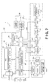
- a timer 101 (an example of non-operating-time recognizing part as a state-quantity recognizing part) that measures a non-operating time Tn of the gear pump 15g
- a standard-time setting part 102 (an example of standard-state-quantity setting part) in which a standard time Ts (an example of standard state quantity) being a standard for carrying out the preliminary operation is set
- a judging part 103 that is adapted to judge that the inside of the gear pump 15g is dry, when the non-operating time Tn measured by the timer 101 is equal to or longer than the standard time Ts set in the standard-time setting part 102.
- the controlling part 11 is adapted to carry out the preliminary operation for wetting the inside of the gear pump 15g when it is judged by the judging part 103 that the non-operating time Tn is equal to or longer than the standard time Ts, that is, when it is judged that the inside of the gear pump 15g is dry.
- a flushing operation of the ink is carried out from the recording head 4 to the capping member 15 in such a manner that a predetermined volume of the ink is ejected into the capping member 15, and then the gear pump 15g is caused to operate for a predetermined time.
- the print engine 31 includes a paper feeding motor 13 as a paper feeding mechanism, a pulse motor 7 as a head scanning mechanism, and an electric driving system 39 of the recording head 4.
- the electric driving system 39 of the recording head 4 includes shift registers 40, latch circuits 41, level shifters 42 and switching units 43 and the piezoelectric vibrating members 21, which are electrically connected in the order.
- the shift registers 40 correspond to the respective nozzles 17, the latch circuits 41 correspond to the respective nozzles 17, the level shifters 42 correspond to the respective nozzles 17, and the switching units 43 correspond the respective nozzles 17, respectively.
- the piezoelectric vibrating members 21 also correspond to the respective nozzles 17 of the recording head 4, respectively.
- the driving signal maybe selectively supplied to each piezoelectric vibrating member 21.
- a drop of the ink may be jetted from a nozzle 17 or a meniscus of ink may be caused to minutely vibrate.
- a necessary initializing operation is conducted at first.
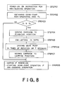
- a non-operating time Tn of the gear pump 15g is measured i.e. obtained by the timer 101 (STEP 02).
- the judging part 103 judges whether the obtained non-operating time Tn is equal to or longer than the standard time Ts set in the standard-time setting part 102 or not (STEP 03).
- the controlling part 11 Specifically, via the control by the controlling part 11, the recording head 4 (the carriage 5) and the capping member 15 are moved to the flushing position (waiting position) (STEP 04). In that state, via the control by the controlling part 11, a predetermined volume of the ink, for example, N dots of the ink are jetted out by means of a flushing operation (STEP 05). Thus, the predetermined volume of the ink is ejected into the inside of the capping member 15.
- the gear pump 15g is caused to operate n times of rotation or for t seconds (STEP 06).
- the ink ejected into the inside of the capping member 15 is conveyed into the inside of the gear pump 15g, so that the inside of the gear pump 15g is wetted, that is, returned to a wet state.
- the gear pump 15g is returned to such a state that the gear pump 15g is able to provide a negative pressure greater than -5 kPa, preferably -15 kPa (The above n times of rotation or t seconds is set to satisfy this condition).
- the recording head 4 (the carriage 5) and the capping member 15 are moved to the capping position (home position), and the recording head 4 is sealed by the capping member 15 (STEP 07). Then, the state remains as a waiting state (STEP 08).
- the recording head 4 After the initializing operation, when printing data corresponding to one line is outputted from the outputting buffer of the RAM 33, the recording head 4 conducts a maintenance operation (recovering operation) before a recording operation for the one line.
- the maintenance operation is conducted for keeping ability of the recording head 4 to jet drops of the ink.
- the maintenance operation may be suitably selected from an ink-sucking operation, a flushing operation, a minutely-vibrating operation, and so on.
- the release-valve mechanism 15v is closed by the frame F or the like to seal the inside of the capping member 15, and thereafter the gear pump 15g is caused to operate. Then, the ink is sucked from the nozzles 17 of the recording head 4 by the gear pump 15g. At that time, since the gear pump 15g is caused to operate when there is a wet state in the inside of the gear pump 15g, the ink-sucking action can be satisfactorily assured.
- the recording operation is conducted in the objective recording area based on the printing data. Specifically, while the recording head 4 is moved in the main scanning direction, drops of the ink can be jetted from the nozzles 17 at respective suitable timings.
- the maintenance operation may be conducted under certain conditions. If the ink-sucking operation is conducted as the maintenance operation for a case wherein the electric power continues to be supplied to the printer 1 for a long time, before the ink-sucking operation is conducted, the preliminary operation for the gear pump 15g is carried out when necessary.
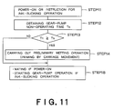
- the flowchart of the preliminary operation in the case is substantially the same as that just after the electric power has started to be supplied to the printer 1 (see Fig. 7). That is, after the instruction for the ink-sucking operation has been confirmed (STEP 01), a non-operating time Tn of the gear pump 15g is measured i.e. obtained by the timer 101 (STEP 02).
- the judging part 103 judges whether the obtained non-operating time Tn is equal to or longer than the standard time Ts set in the standard-time setting part 102 or not (STEP 03).
- the controlling part 11 Specifically, via the control by the controlling part 11, the recording head 4 (the carriage 5) and the capping member 15 are moved to the flushing position (waiting position) (STEP 04). In that state, via the control by the controlling part 11, a predetermined volume of the ink, for example, N dots of the ink are jetted out by means of a flushing operation (STEP 05). Thus, the predetermined volume of the ink is ejected into the inside of the capping member 15. Then, the gear pump 15g is caused to operate n times of rotation or for t seconds (STEP 06).
- the ink ejected into the inside of the capping member 15 is conveyed into the inside of the gear pump 15g, so that the inside of the gear pump 15g is wetted, that is, returned to a wet state. Then, via the control by the controlling part 11, the recording head 4 (the carriage 5) and the capping member 15 are moved to the capping position (home position), and the recording head 4 is sealed by the capping member 15 (STEP 07). Thereafter, the ink-sucking operation starts to be carried out under that state (STEP 08).
- the ink at the nozzles 17 can be sucked by the gear pump 15g that can be relatively easily designed optimally.
- the inside of the cappi ng member 15 is communicated with the atmosphere via the release-valve mechanism 15v that is normally open, so that it is prevented that the menisci of the ink be broken down by air expansion/contraction caused by the temperature change or the like.
- the preliminary operation for wetting the inside of the gear pump 15g is carried out only when the non-operating time Tn of the gear pump 15g is equal to or longer than the standard time Ts.
- the inside of the gear pump 15g is efficiently returned to the wet state from the dry state.
- the inside of the gear pump 15g is wetted with the ink.
- it is unnecessary to prepare a special wetting agent. Therefore, it is unnecessary to provide any mechanism for introducing a wetting agent, that is, the structure is simpler.
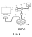
- Fig. 9 is a schematic sectional view of a gear pump and periphery thereof in an ink-jetting recording apparatus of a second embodiment according to the invention.
- a wetting-agent tank 112 is connected to the pump frame 15f of the gear pump 15g on the side of the capping member 15, via a wetting-agent supplying way 111.
- An optimum wetting agent is selected for optimally wetting the inside of the gear pump 15g, and the wetting-agent tank 112 is filled with the selected wetting agent.
- Two check valves 113, 114 are provided on the way of the wetting-agent supplying way 111.
- a priming pump 115 is provided between the two check valves. The priming pump 115 is adapted to operate when the priming pump 115 itself is pushed. When the priming pump 115 operates, the wetting agent is supplied from the wetting-agent tank 112 into the inside of the gear pump 15g.
- a pushing member 5p for pushing the priming pump 115 is formed on the carriage 5 integrated with the recording head 4.
- the pushing member 5b is adapted to push the priming pump 115 while the recording head 4 is moved in the main scanning direction, in order to cause the priming pump 115 to operate.
- controlling part 11 is adapted not to cause the gear pump 15g to operate when the controlling part 11 functions as a preliminary-operation carrying-cut part.
- Figs. 10A to 10C show an example of arrangement sui ted for the pushing member 5p to push the priming pump 115.
- a plate member 130 is provided to come in contact with the carriage 5, and the capping member 15 is movable while keeping a horizontal position via a parallel-linkage mechanism 131.
- the carriage 5 pushes and moves the plate member 130 (and also slides vertically). Then, the capping member 15 is moved up by the parallel-linkage mechanism 131 to seal the recording head 4. At that time, the pushing member 5p comes in contact with the priming pump 115, but doesn't push the priming pump 115.
- the carriage 5 is further moved to the priming pump 115.
- a necessary initializing operation is conducted at first.
- a non-operating time Tn of the gear pump 15g is measured i. e. obtained by the timer 101 (STEP 12).
- the judging part 103 judges whether the obtained non-operating time Tn is equal to or longer than the standard time Ts set in the standard-time setting part 102 or not (STEP 13).
- the judge result is "Yes”
- the recording head 4 the carriage 5
- the priming pump 115 to operate via the pushing member 5p.
- the wetting agent is supplied from the wetting-agent tank 112 into the inside of the gear pump 15g, so that the inside of the gear pump 15g is wetted, that is, returned to a wet state.
- the state remains as a waiting state (STEP 18).
- the recording head 4 After the initializing operation, when printing data corresponding to one line is outputted from the outputting buffer of the RAM 33, the recording head 4 conducts a maintenance operation (recovering operation) before a recording operation for the one line.
- the maintenance operation is conducted for keeping ability of the recording head 4 to jet drops of the ink.
- the maintenance operation may be suitably selected from an ink-sucking operation, a flushing operation, a minutely-vibrating operation, and so on.
- the release-valve mechanism 15v is closed by the frame F or the like to seal the inside of the capping member 15, and thereafter the gear pump 15g is caused to operate. Then, the ink is sucked from the nozzles 17 of the recording head 4 by the gear pump 15g. At that time, since the gear pump 15g is caused to operate when there is a wet state in the inside of the gear pump 15g, the ink-sucking action can be satisfactorily assured.
- the recording operation is conducted in the objective recording area based on the printing data. Specifically, while the recording head 4 is moved in the main scanning direction, drops of the ink can be jetted from the nozzles 17 at respective suitable timings.
- the maintenance operation may be conducted under certain conditions. If the ink-sucking operation is conducted as the maintenance operation for a case wherein the electric power continues to be supplied to the printer 1 for a long time, before the ink-sucking operation is conducted, the preliminary operation for the gear pump 15g is carried out when necessary.
- the preliminary operation for wetting the inside of the gear pump 15g is carried out only when the non-operating time Tn of the gear pump 15g is equal to or longer than the standard time Ts.
- the inside of the gear pump 15g is efficiently returned to the wet state from the dry state.
- the inside of the gear pump 15g is wetted with a special wetting agent, that is, an optimum wetting agent may be supplied at an optimum flow rate.
- the manner of causing the priming pump to operate is not limited to the above one using the pushing member 5p, but also may be various other manners.
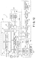
- Fig. 12 is a schematic block diagram for explaining an electric structure of an ink-jetting recording apparatus of a third embodiment according to the invention.
- the controlling unit 11 is adapted to automatically function as a preliminary-operation carrying-out part based on the judge result by the judging part 103.
- the controlling part 11 is adapted to function as a preliminary-operation carrying-out part after an instruction is inputted by a user.
- a displaying part 105 that displays judge result by the judging part 103, and an inputting part 106 into which a preliminary-operation instruction is manually inputted.
- the controlling part 11 is adapted to carry out a preliminary operation for wetting the inside of the gear pump 15g based on the preliminary-operation instruction inputted into the inputting part 106.
- the third embodiment when the non-operating time Tn of the gear pump 15g is equal to or longer than the standard time Ts, this information is displayed by the displaying part 105. Then, the user can estimate that the inside of the gear pump 15g becomes dry to some extent. Thus, by the user inputting the preliminary-operation instruction into the inputting part 106, the preliminary operation for wetting the inside of the gear pump 15g can be carried out efficiently.
- Fig. 13 is a schematic block diagram for explaining an electric structure of an ink-jetting recording apparatus of a fourth embodiment according to the invention.
- the controlling part 11 is adapted to function as a preliminary-operation carrying-out part after an instruction is inputted by a user.
- a displaying part 105 that displays judge result by the judging part 103, and an inputting part 106 into which a preliminary-operation instruction is manually inputted.
- the controlling part 11 is adapted to carry out a preliminary operation for wetting the inside of the gear pump 15g based on the preliminary-operation instruction inputted into the inputting part 106.
- the fourth embodiment when the non-operating time Tn of the gear pump 15g is equal to or longer than the standard time Ts, that information is displayed by the displaying part 105. Then, the user can estimate that the inside of the gear pump 15g becomes dry to some extent. Thus, by the user inputting the preliminary-operation instruction into the inputting part 106, the preliminary operation for wetting the inside of the gear pump 15g can be carried out efficiently.
- the priming pump 115 may be directly caused to operate by the preliminary-operation instruction.
- the non-operating time Tn of the gear pump 15g is used as a state quantity related to the dry state in the inside of the gear pump 15g.
- a continuous open time of the capping member 15, an elapsed time in an OFF state of an electric power source, or the like maybe used instead of the non-operating time Tn.
- the state quantity related to the dry state in the inside of the gear pump 15g may be a state quantity related to an operating state of the gear pump 15 after the gear pump 15g has been driven for a predetermined time.
- a pressure in the capping member 15 after the gear pump 15g has been driven for a predetermined time is used as a state quantity related to an operating state of the gear pump 15g. If the pressure in the capping member 15 after the gear pump 15g has been driven for a predetermined time doesn't reach a predetermined negative pressure, it can be estimated that the inside of the gear pump 15g is in a dry state.
- FIG. 14 is a schematic block diagram for explaining an electric structure of an ink-jetting recording apparatus of a fifth embodiment according to the invention.
- a pressure detecting part 101' is provided instead of the timer 101.
- the pressure detecting part 101' may consist of a film sensor or the like, and may be arranged in the suction way 15w from the capping member 15 or the inside of the capping member 15 to the gear pump 15g.
- a standard-negative-pressure setting part 102' in which a standard negative pressure Ps being a standard for carrying out a preliminary operation is set, is provided instead of the standard-time setting part 102, in which the s tandard time Ts being a s tandard for carrying out a preliminary operation is set.
- the judging part 103 is adapted to judge that the inside of the gear pump 15g is dry, when the pressure in the capping member Pn recognized by the pressure detecting part 101' is equal to or above the standard negative pressure Ps set in the standard-negative-pressure setting part 102'.
- the controlling part 11 of the embodiment is adapted to cause the gear pump 15g to operate for a predetermined time in order to judge (estimate) the inside state of the gear pump 15g. Thereafter, when the judging part 103 judges that the pressure in the capping member Pn is equal to or above the standard negative pressure Ps (doesn' t exceed the standard negative pressure Ps), that is, when the judging part 103 judges that the inside of the gear pump 15g is in a dry state, the controlling part 11 is adapted to carry out a preliminary operation for wetting the inside of the gear pump 15g.
- a necessary initializing operation is conducted at first.
- the gear pump 15g is caused to operate for a predetermined time (STEP 11), and a pressure in the capping member Pn is measured i.e. obtained by the pressure detecting part 101' (STEP 02').
- the judging part 103 judges whether the obtained pressure in the capping member Pn is equal to or above the standard negative pressure Ps set in the standard-negative-pressure setting part 102' or not (STEP 03').
- the controlling part 11 Specifically, via the control by the controlling part 11, the recording head 4 (the carriage 5) and the capping member 15 are moved to the flushing position (waiting position) (STEP 04). In that state, via the control by the controlling part 11, a predetermined volume of the ink, for example, N dots of the ink are jetted out by means of a flushing operation (STEP 05). Thus, the predetermined volume of the ink is ejected into the inside of the capping member 15.
- the gear pump 15g is caused to operate n times of rotation or for t seconds (STEP 06).
- the ink ejected into the inside of the capping member 15 is conveyed into the inside of the gear pump 15g, so that the inside of the gear pump 15g is wetted, that is, returned to a wet state.
- the recording head 4 (the carriage 5) and the capping member 15 are moved to the capping position (home position) , and the recording head 4 is sealed by the capping member 15 (STEP 07).
- the state remains as a waiting state (STEP 08).
- the recording head 4 After the initializing operation, when printing data corresponding to one line is outputted from the outputting buffer of the RAM 33, the recording head 4 conducts a maintenance operation (recovering operation) before a recording operation for the one line.
- the maintenance operation is conducted for keeping ability of the recording head 4 to jet drops of the ink.
- the maintenance operation may be suitably selected from an ink-sucking operation, a flushing operation, a minutely-vibrating operation, and so on.
- the release-valve mechanism 15v is closed by the frame F or the like to seal the inside of the capping member 15, and thereafter the gear pump 15g is caused to operate. Then, the ink is sucked from the nozzles 17 of the recording head 4 by the gear pump 15g. At that time, since the gear pump 15g is caused to operate when there is a wet state in the inside of the gear pump 15g, the ink-sucking action can be satisfactorily assured.
- the recording operation is conducted in the objective recording area based on the printing data. Specifically, while the recording head 4 is moved in the main scanning direction, drops of the ink can be jetted from the nozzles 17 at respective suitable timings.
- the maintenance operation may be conducted under certain conditions. If the ink-sucking operation is conducted as the maintenance operation for a case wherein the electric power continues to be supplied to the printer 1 for a long time, before the ink-sucking operation is conducted, the preliminary operation for the gear pump 15g is carried out when necessary.
- the flowchart of the preliminary operation in the case is substantially the same as that just after the electric power has started to be supplied to the printer 1 (see Fig. 15). That is, after the instruction for the ink-sucking operation has been confirmed (STEP 01), the gear pump 15g is caused to operate for a predetermined time (STEP 11), and a pressure in the capping member Pn is measured i.e. obtained by the pressure detecting part 101' (STEP 02').
- the judging part 103 judges whether the obtained pressure in the capping member Pn is equal to or above the standard negativepressure Ps set in the standard-negative-pressure setting part 102' or not (STEP 03').
- the controlling part 11 Specifically, via the control by the controlling part 11, the recording head 4 (the carriage 5) and the capping member 15 are moved to the flushing position (waiting position) (STEP 04). In that state, via the control by the controlling part 11, a predetermined volume of the ink, for example, N dots of the ink are jetted out by means of a flushing operation (STEP 05) . Thus, the predetermined volume of the ink is ejected into the inside of the capping member 15. Then, the gear pump 15g is caused to operate n times of rotation or for t seconds (STEP 06).
- the ink ejected into the inside of the capping member 15 is conveyed into the inside of the gear pump 15g, so that the inside of the gear pump 15g is wetted, that is, returned to a wet state. Then, via the control by the controlling part 11, the recording head 4 (the carriage 5) and the capping member 15 are moved to the capping position (home position), and the recording head 4 is sealed by the capping member 15 (STEP 07). Thereafter, the ink-sucking operation starts to be carried out under that state (STEP 08).
- the preliminary operation for wetting the inside of the gear pump 15g can be carried out.
- the inside of the gear pump 15g is efficiently returned to the wet state from the dry state.
- a state quantity related to an operating state of the gear pump 15g a state quantity related to an ink flow after the gear pump 15g has been driven for a predetermined time may be also used. If an expected ink flow isn't generated after the gear pump 15g has been driven for a predetermined time, it can be estimated that the inside of the gear pump 15g is in a dry state.
- the state quantity related to an ink flow may be detected by a photon-interrupter provided in the suction way 15w, or an electrode provided in the capping member 15 or the gear pump 15g, or the like.
- an ink flow into the gear pump 15g may be detected, by detecting change in a rotational load of a motor (not shown) for driving the gear pump 15g from an electrical current waveform of the motor.
- gear pump is used in the above embodiments.
- any roots pump, any quimby screw pump, any vane pump, or any other built-in slide-rotator type of positive displacement pump may be used.
- Fig. 16A is a perspective view of a roots pump 200
- Fig. 16B is an exploded view of the roots pump 200
- Fig. 16C is a plan view of the roots pump 200 from which a lid 207 is removed.
- the roots pump 200 includes: a pump frame (casing) 201 having a suction port 201a connected to the suction way 15w; and a first rotator 202 and a second rotator 203 that are in a rolling contact with each other and that are contained in the pump frame 201.
- the first rotator 202 is rotated by means of a first driving shaft 204 that pierces the pump frame 201 and/or the lid 207.
- the second rotator 203 is rotated by means of a second driving shaft 205 that pierces the pump frame 201 and/or the lid 207.
- the first driving shaft 204 and the second driving shaft 205 are arranged in parallel.
- the pump frame (casing) 201 is sealed by the lid 207 via a packing 206.
- the pump frame 201 has a discharging port 201b.
- the suction port 201a and the discharging port 201b are located opposite with respect to a slide area between the rotators 202, 203 and the pump frame 201.
- the roots pump 200 is formed in such a precise manner that a gap between the first and second rotators 202, 203 and the pump frame 201 is not more than 100 micron in both a radial direction and a thickness direction.
- the first rotator 202 and the second rotator 203 are synchronously rotated in a direction shown by arrows in Fig. 16B by the first driving shaft 204 and the second driving shaft 205, the first rotator 202 and the second rotator 203 slide on the pump frame 201 (via liquid (ink) menisci) while the first rotator 202 and the second rotator 203 roll on each other.
- the ink is conveyed from an IN area in the pump frame 201 (on the side of the suction port 201a) to an OUT area therein (on the side of the discharging port 201b) to achieve a pump function.
- the release-valve mechanism 15v that is normally open may be provided at the capping member 15.
- the release-valve mechanism 15v is adapted to close only when the capping member 15 comes in contact wi th a frame F or the like, correspondingly to when it is necessary to suck the ink.
- the inside of the capping member 15 is normally communicated with the atmosphere, so that it is prevented the menisci are broken down by temperature change or the like, while the capping member 15 is suitably sealed when the ink has to be sucked.
- Fig. 17A is a perspective view of a quimby screw pump 300
- Fig. 17B is an exploded view of the quimby screw pump 300
- Fig. 17C is a partial sectional view of the quimby screw pump 300.
- the quimby screw pump 300 includes: a pump frame (casing) 301 having a suction port 301a connected to the suction way 15w; and a driving spiral 302 and a driven spiral 303 that are engaged with each other and slidably contained in the pump frame 301 (via liquid (ink) menisci).
- the driving spiral 302 is rotated by means of a driving shaft 304 that pierces the pump frame 301 and/or a lid 307.
- the driven spiral 303 is pivotally supported by the pump frame 301 and the lid 307 via a driven shaft 305 that is parallel to the driving shaft 304.
- the pump frame (casing) 301 is sealed by the lid 307 via a packing 306.
- the lid 307 has a discharging port 307a.
- the suction port 301a and the discharging port 307a are located opposite with respect to a slide area between the spirals 302, 303 and the pump frame 301.
- the quimby screw pump 300 is formed in such a precise manner that a gap between the driving and driven spirals 302, 303 and the pump frame 301 is not more than 100 micron.
- the driven spiral 303 engaged with the driving spiral 302 is also rotated, so that the ink is conveyed from an IN area in the pump frame 301 (on the side of the suction port 301a) to an OUT area therein (on the side of the discharging port 307a) to achieve a pump function. Therefore, for example, similarly to the case shown in Figs. 4A and 4B, the release-valve mechanism 15v that is normally open may be provided at the capping member 15.
- the release-valve mechanism 15v is adapted to close only when the capping member 15 comes in contact with a frame F or the like, correspondingly to when it is necessary to suck the ink.
- the inside of the capping member 15 is normally communicated with the atmosphere, so that it is prevented the menisci are broken down by temperature change or the like, while the capping member 15 is suitably sealed when the ink has to be sucked.
- Fig. 18A is a perspective view of a vane pump 400
- Fig. 18B is an exploded view of the vane pump 400
- Fig. 18C is a plan view of the vane pump 400 from which a lid 407 is removed.
- the vane pump 400 includes: a pump frame (casing) 401 having a suction port 401a connected to the suction way 15w; and a rotor 402 that is contained in the pump frame 401.
- the rotor 402 has a cylindrical shape whose diameter is smaller than a diameter of a cylindrical space in the pump frame 401.
- the rotor 402 is rotated by means of a driving shaft 404 that pierces the pump frame 401 and/or the lid 407.
- the driving shaft 404 is eccentrically located with respect to a center of the cylindrical space in the pump frame 401.
- Apart of the outside periphery of the rotor 402 is adapted to slide on an inside surface of the pump frame 401 (via liquid (ink) menisci).
- a plurality of (six in the shown example) concave portions 402r is formed in the outside periphery of the rotor 402, at substantially even intervals in a circumferential direction thereof.
- a blade 403 is provided in each concave portion 402r via a spring 402s.
- the spring 402s provides a biasing force tending to move the blade 403 outwardly.
- the pump frame (casing) 401 is sealed by the lid 407 via a packing 406.
- the pump frame 401 has a discharging port 401b.
- the suction port 401a and the discharging port 401b are located in such a manner that a slide area between the rotor 402 and the pump frame 401 is sandwiched between the suction port 401a and the discharging port 401b.
- the vane pump 400 is formed in such a precise manner that a gap between the rotor 402 and the pump frame 401 is not more than 100 micron.
- the release-valve mechanism 15v that is normally open may be provided at the capping member 15.
- the release-valve mechanism 15v is adapted to close only when the capping member 15 comes in contact with a frame F or the like, correspondingly to when it is necessary to suck the ink.
- the inside of the capping member 15 is normally communicated with the atmosphere, so that it is prevented the menisci are broken down by temperature change or the like, while the capping member 15 is suitably sealed when the ink has to be sucked.
- a reciprocating-mechanism type of positive displacement pump such as a piston pump, a bellows pump, a diaphragm pump, or the like may be also used.
- Fig. 20 is a schematic sectional view of a piston pump 500.
- the piston pump 500 includes a pump frame (cylinder) 501 whose volume is changeable by a reciprocating motion of a piston 502.
- a suction port 501a which is connected to the suction way 15w, is formed at the pump frame 501 via a first check valve 501c.
- a discharging port 501b is also formed at the pump frame 501 via a second check valve 501d.
- the release-valve mechanism 15v that is normally open may be provided at the capping member 15.
- the release-valve mechanism 15v is adapted to close only when the capping member 15 comes in contact with a frame F or the like, correspondingly to when it is necessary to suck the ink.
- the inside of the capping member 15 is normally communicated with the atmosphere, so that it is prevented the menisci are broken down by temperature change or the like, while the capping member 15 is suitably sealed when the ink has to be sucked.
- Fig. 21 is a schematic sectional view of a bellows pump 600.
- the bellows pump 600 includes a bellows frame 601 whose volume is changeable by a reciprocating mechanism 602.
- a suction port 601a which is connected to the suction way 15w, is formed at the bellows frame 601 via a first check valve 601c.
- a discharging port 601b is also formed at the bellows frame 601 via a second check valve 601d.
- the ink is introduced from the suction port 601a into the bellows frame 601 through the first check valve 601c.
- the second check valve 601d is not opened, so that the ink is not introduced back through the discharging port 601b.
- the ink is conveyed from the inside of the bellows frame 601 to the discharging port 601b through the second check valve 601d.
- the first check valve 601c is not opened, so that the ink is not conveyed back to the suction port 601a.
- the release-valve mechanism 15v that is normally open may be provided at the capping member 15.
- the release-valve mechanism 15v is adapted to close only when the capping member 15 comes in contact with a frame F or the like, correspondingly to when it is necessary to suck the ink.
- the inside of the capping member 15 is normally communicated with the atmosphere, so that it is prevented the menisci are broken down by temperature change or the like, while the capping member 15 is suitably sealed when the ink has to be sucked.
- Fig. 22 is a schematic sectional view of a diaphragm pump 700.
- the diaphragm pump 700 includes a pump frame (cylinder) 701 whose volume is changeable by a reciprocating motion of a diaphragm 702.
- a suction port 701a which is connected to the suction way 15w, is formed at the pump frame 701 via a first check valve 701c.
- a discharging port 701b is also formed at the pump frame 701 via a second check valve 701d.
- the ink is introduced from the suction port 701a into the pump frame 701 through the first check valve 701c.
- the second check valve 701d is not opened, so that the ink is not introduced back through the discharging port 701b.
- the ink is conveyed from the inside of the pump frame 701 to the discharging port 701b through the second check valve 701d.
- the first check valve 701c is not opened, so that the ink is not conveyed back to the suction port 701a.
- This reciprocating motion of the diaphragm 702 is repeated, so that the ink is conveyed from an IN area in the pump frame 701 (on the side of the suction port 701a) to an OUT area therein (on the side of the discharging port 701b) to achieve a pump function.
- the release-valve mechanism 15v that is normally open may be provided at the capping member 15.
- the release-valve mechanism 15v is adapted to close only when the capping member 15 comes in contact with a frame F or the like, correspondingly to when it is necessary to suck the ink.
- the inside of the capping member 15 is normally communicated with the atmosphere, so that it is prevented the menisci are broken down by temperature change or the like, while the capping member 15 is suitably sealed when the ink has to be sucked.
- the controlling part 11, the timer 101, the standard-time setting part 102, the judging part 103, and so on can be materialized by a computer system.
- a program for materializing the above one or more components in a computer system, and a storage unit 201 storing the program and capable of being read by a computer, are intended to be protected by this application.
- one or more components may be materialized in a computer system by using a general program such as an OS, a program including a command or commands for controlling the general program, and a storage unit 202 storing the program and capable of being read by a computer, are intended to be protected by this application.
- a general program such as an OS
- a program including a command or commands for controlling the general program and a storage unit 202 storing the program and capable of being read by a computer
- Each of the storage units 201 and 202 can be not only a substantial object such as a floppy disk or the like, but also a network for transmitting various signals.
- the ink-jetting printer as a liquid ejecting apparatus according to the invention.
- this invention is intended to apply to general liquid ejecting apparatuses widely.
- a liquid may be glue, nail polish, conductive liquid (liquidmetal) or the like, instead of the ink.
- this invention can be applied to a manufacturing unit for color filters of a display apparatus such as LCD.
Landscapes
- Ink Jet (AREA)
- Reciprocating Pumps (AREA)
- Coating Apparatus (AREA)
- Particle Formation And Scattering Control In Inkjet Printers (AREA)
- Control Of Positive-Displacement Pumps (AREA)
Abstract
Description
- This invention relates to a liquid ejecting apparatus having a head member capable of ejecting a drop of liquid from a nozzle.
- Generally, an ink-jetting recording apparatus, which is an example of liquid ejecting apparatus, includes a recording head having a nozzle, an ink-jetting means for ejecting ink from the nozzles (for example, a piezoelectric vibrating member or a heat-generating member), and a main controlling part that controls the ink-jetting means based on recording data.
- The nozzle of the recording head may be clogged with thickened ink. In order to prevent clogging of the nozzle with the thickened ink, the thickened ink may be forcibly sucked, from the nozzle.
- Tube pumps are commonly used for forcibly sucking the thickened ink. In a tube pump, a tube is collapsed by a pulley, and then returns to an original shape of the tube due to rigidity thereof. The latter volume change provides a suction power.
- However, the rigidity of the tube may change depending on temperature change or the like, so that suction speed may also change undesirably. In addition, in order to increase a volume of sucked ink, it is effective to raise a rotation speed of the pulley. However, there is no effect if the pulley is rotated at a speed faster than that at which the collapsed tube returns to the original shape. That is, the volume of sucked ink can not be increased greatly. In addition, if the diameter of the tune is increased, the volume of sucked ink maybe increased. However, in that case, the thickness of the tube has to be increased in order to maintain the rigidity of the tube, which results in the larger sucking system.
- The inventor has paid attention to a built-in slide-rotator type of positive displacement pump, because it is easy to downsize and optimally design the built-in slide-rotator type of positive displacement pump depending on a driving rotational speed and/or a required flow rate.
- However, in the built-in slide-rotator type of positive displacement pump, there is the following problem, that is, when the inside of the positive displacement pump comes to nearly a dry state due to a long disuse or the like, the seal tightness between the pump frame (casing) and the slide-rotator (gear or the like) may be weakened so that the suction power may be considerably reduced.
- JP Laid-Open Publication No. 55-64178 discloses a technique wherein a wetting agent is injected from outside into between a seal ring and a seal plate before driving a gear pump (an example of built-in slide-rotator type of positive displacement pump) , when a kind of heated liquid is conveyed by the gear pump.
- However, it is necessary to inject the wetting agent into the built-in slide-rotator type of positive displacement pump only when the inside comes to nearly a dry state. That is, if the wetting agent is injected in the built-in slide-rotator type of positive displacement pump always before driving the positive displacement pump, the wetting agent may be wasted in surplus. This is not preferable.
- The object of this invention is to solve the above problems, thatis, to provide a liquid ejecting apparatus includingabuilt-in slide-rotator type of positive displacement pump wherein the inside of the positive displacement pump can be efficiently returned from a dry state to a wet state.
- In this specification and claims, the "wet state" in the inside of the positive displacement pump means a state capable of providing a negative pressure equal to or greater than -5 kPa, preferably -15 kPa, by means of an operation of the positive displacement pump.
- In order to achieve the object, the invention is a liquid ejecting apparatus comprising: a head member having a nozzle and a liquid-ejecting unit that ejects liquid in the nozzle; a main controlling part that drives the liquid-ejecting unit based on ejecting data; a capping member relatively movable between a position away from the head member and a position in contact with the head member; a suction way communicated with an inside of the capping member; a built-in slide-rotator type of positive displacement pump provided in the suction way; a state-quantity recognizing part that recognizes a state quantity related to a dry state in an inside of the built-in slide-rotator type of positive displacement pump; a standard-state-quantity setting part in which a standard state quantity is set, the standard state quantity being a standard for carrying out a preliminary operation for wetting the inside of the positive displacement pump; a judging part that judges whether the inside of the positive displacement pump is dry or not, by comparing the state quantity recognized by the state-quantity recognizing part with the standard state quantity set in the standard-state-quantity setting part; and a preliminary-operation carrying-out part that carries out the preliminary operation for wetting the inside of the positive displacement pump, when it is judged by the judging part that the inside of the positive displacement pump is dry.
- According to the above feature, since the preliminary operation for wetting the inside of the positive displacement pump is carried out only when it is judged that the inside of the positive displacement pump is dry, the inside of the positive displacement pump can be efficiently returned from a dry state to a wet state.
- Alternatively, the invention is a liquid ejecting apparatus comprising: a head member having a nozzle and a liquid-ejecting unit that ejects liquid in the nozzle; a main controlling part that drives the liquid-ejecting unit based on ejecting data; a capping member relatively movable between a position away from the head member and a position in contact with the head member; a suction way communicated with an inside of the capping member; a built-in slide-rotator type of positive displacement pump provided in the suction way; a state-quantity recognizing part that recognizes a state quantity related to a dry state in an inside of the built-in slide-rotator type of positive displacement pump; a standard-state-quantity setting part in which a standard state quantity is set, the standard state quantity being a standard for carrying out a preliminary operation for wetting the inside of the positive displacement pump; a judging part that judges whether the inside of the positive displacement pump is dry or not, by comparing the state quantity recognized by the state-quantity recognizing part with the standard state quantity set in the standard-state-quantity setting part; a displaying part that displays judge result by the judging part; an inputting part into which a preliminary-operation instruction is manually inputted; and a preliminary-operation carrying-out part that carries out the preliminary operation for wetting the inside of the positive displacement pump, basedon the preliminary-operation instruction inputted into the inputting part.
- According to the above feature, when it is judged that the inside of the positive displacement pump is dry, the judge result is displayed by the displaying unit, so that an operator (user) can estimate or notice a dry state in the inside of the positive displacement pump. This makes it possible to efficiently carry out the preliminaryoperation for wetting the inside of thepositive displacement pump.
- For example, the preliminary-operation carrying-out part is adapted to cause the liquid-ejecting unit to eject liquid from the nozzle into the capping member, and thereafter drive the built-in slide-rotator type of positive displacement pump for a predetermined preliminary-operation time.
- In the case, by means of the liquid ejected by the liquid-ejecting unit, thebuilt-in slide-rotator type of positive displacement pump is efficiently returned to a wet state. Thus, it is unnecessary to prepare a special wetting agent. In addition, it is unnecessary to provide another mechanism for introducing a wetting agent, that is, the structure is simpler.
- Alternatively, thebuilt-in slide-rotator type of positive displacement pump may have a pump frame connected to the suction way, and a wetting-agent supplying way for supplying a wetting agent may be connected to the pump frame. In the case, it is preferable that the preliminary-operation carrying-out part is adapted to supply the wetting agent into the pump frame via the wetting-agent supplying way. In the case, an optimumwetting agent can be supplied at an optimum flow rate.
- For example, if a priming pump is provided in the wetting-agent supplying way, it is preferable that the preliminary-operation carrying-out part is adapted to supply the wetting agent into the pump frame by causing the priming pump to operate.
- In addition, if the head member is integrated with a pushing member, and the pushing member is movable in a direction in such a manner that the pushing member can push the priming pump to cause the priming pump to operate, it is preferable that the preliminary-operation carrying-out part is adapted to supply the wetting agent into the pump frame by causing the priming pump to operate via the pushing member by moving the head member.
- Alternatively, the invention is a liquid ejecting apparatus comprising: a head member having a nozzle and a liquid-ejecting unit that ejects liquid in the nozzle; a main controlling part that drives the liquid-ejecting unit based on ejecting data; a capping member relatively movable between a position away from the head member and a position in contact with the head member; a suction way communicated with an inside of the capping member; a built-in slide-rotator type of positive displacement pump provided in the suction way; a state-quantity recognizing part that recognizes a state quantity related to a dry state in an inside of the built-in slide-rotator type of positive displacement pump; a standard-state-quantity setting part in which a standard state quantity is set, the standard state quantity being a standard for carrying out a preliminary operation for wetting the inside of the positive displacement pump; a judging part that judges whether the inside of the positive displacement pump is dry or not, by comparing the state quantity recognized by the state-quantity recognizing part with the standard state quantity set in the standard-state-quantity setting part; and a displaying part that displays judge result by the judging part; wherein the built-in slide-rotator type of positive displacement pump has a pump frame connected to the sucti on way; a wetting-agent supplying way for supplying a wetting agent is connected to the pump frame; a priming pump is provided in the wetting-agent supplying way; and a manual inputting part for causing the priming pump to operate is connected to the priming pump.
- According to the above feature, when it is judged that the inside of the positive displacement pump is dry, the judge result is displayed by the displaying unit, so that an operator (user) can estimate or notice a dry state in the inside of the positive displacement pump. This makes it possible to efficiently cause the priming pump to operate for wetting the inside of the positive displacement pump.
- For example, the state quantity related to a dry state in an inside of the built-in slide-rotator type of positive displacement pump is a non-operating time of the positive displacement pump. In the case, the state-quantity recognizing part is a non-operating-time recognizing part that recognizes the non-operating time, the standard state quantity being a standard for carrying out a preliminary operation is a standard time being a standard for carrying out a preliminary operation, the standard-state-quantity setting part is a standard-time setting part in which the standard time is set, and the judging part is adapted to judge that the insideof the positive displacement pump is dry, when the non-operating time recognized by the non-operating-time recognizing part is equal to or longer than the standard time set in the standard-time setting part.
- Alternatively, the state quantity related to a dry state in an inside of the built-in slide-rotator type of positive displacement pump may be a continuous open time of the capping member or an elapsed time in an OFF state of an electric power source.
- Alternatively, the state quantity related to a dry state in an inside of the built-in slide-rotator type of positive displacement pump may be a state quantity related to an operating state of the positive displacement pump after the positive displacement pump has been driven for a predetermined time.
- Specifically, for example, the state quantity related to an operating state of the positive displacement pump is a pressure in the capping member after the positive displacement pump has been driven for a predetermined time. If the pressure in the capping member after the positive displacement pump has been driven for a predetermined time doesn' t reach a predetermined negative pressure, it can be estimated that the inside of the positive displacement pump is in a dry state. In the case, the state-quantity recognizing part is a pressure detecting part that recognizes the pressure in the capping member, the standard state quantity being a standard for carrying out a preliminary operation is a standard negative pressure being a standard for carrying out a preliminary operation, the standard-state-quantity setting part is a standard-negative-pressure setting part in which the standard negative pressure is set, and the judging part is adapted to judge that the inside of the positive displacement pump is dry, when the pressure in the capping member recognized by the pressure detecting part is equal to or above the standard negative pressure set in the standard-negative-pressure setting part. A film sensor or the like provided in a liquid way may be used as the pressure detecting part.
- Alternatively, the state quantity related to an operating state of the positive displacement pump may be a state quantity related to a liquid flow after the positive displacement pump has been driven for a predetermined time. If an expected liquid flow isn' t generated after the positive displacement pump has been driven for a predetermined time, it can be estimated that the inside of the positive displacement pump is in a dry state. The state quantity related to a liquid flow may be detected by a photon-interrupter provided in a liquid way, or an electrode provided in the capping member or the positive displacement pump, or the like. In addition, a liquid flow into the pump may be detected, by detecting change in a rotational load of a motor for driving the pump from an electrical current waveform of the motor.
- Herein, the built-in slide-rotator type of positive displacement pump means any pump including: a casing member, at least one rotator consisting of one or more parts, and a power transfer device for rotating the rotator, wherein a pump action is achieved by volume change caused by rotation of the rotator in the casing member. For example, the built-in slide-rotator type of positive displacement pump may be any gear pump, any roots pump, any quimby screw pump, any vane pump, or the like.
- In addition, the concept of the present invention can be also applied to cases using a reciprocating-mechanism type of positive displacement pump instead of the built-in slide-rotator type of positive displacement pump. That is, the invention is a liquid ejecting apparatus comprising: a head member having a nozzle and a liquid-ejecting unit that ej ects liquid in the nozzle; a main controlling part that drives the liquid-ejecting unit based on ejecting data; a capping member relatively movable between a position away from the head member and a position in contact with the head member; a suction way communicated with an inside of the capping member; a reciprocating-mechanism type of positive displacement pump provided in the suction way; a state-quantity recognizing part that recognizes a state quantity related to a dry state in an inside of the reciprocating-mechanism type of positive displacement pump; a standard-state-quantity setting part in which a standard state quantity is set, the standard state quantity being a standard for carrying out a preliminary operation for wetting the inside of the positive displacement pump; a judging part that judges whether the inside of the positive displacement pump is dry or not, by comparing the state quantity recognized by the state-quantity recognizing part with the standard state quantity set in the standard-state-quantity setting part; and a preliminary-operation carrying-out part that carries out the preliminary operation for wetting the inside of the positive displacement pump, when it is judged by the judging part that the inside of the positive displacement pump is dry.
- According to the above feature, since the preliminary operation for wetting the inside of the positive displacement pump is carried out only when it is judged that the inside of the positive displacement pump is dry, the inside of the positive displacement pump can be efficiently returned from a dry state to a wet state.
- Alternatively, the invention is a liquid ejecting apparatus comprising: a head member having a nozzle and a liquid-ejecting unit that ejects liquid in the nozzle; a main controlling part that drives the liquid-ejecting unit based on ejecting data; a capping member relatively movable between a position away from the head member and a position in contact with the head member; a suction way communicated with an inside of the capping member; a reciprocating-mechanism type of positive displacement pump provided in the suction way; a state-quantity recognizing part that recognizes a state quantity related to a dry state in an inside of the reciprocating-mechanism type of positive displacement pump ; a standard-state-quantity setting part in which a standard state quantity is set, the standard state quantity being a standard for carrying out a preliminary operation for wetting the inside of the positive displacement pump; a judging part that judges whether the inside of the positive displacement pump is dry or not, by comparing the state quantity recognized by the state-quantity recognizing part with the standard state quantity set in the standard-state-quantity setting part; a displaying part that displays judge result by the judging part; an inputting part into which a preliminary-operation instruction is manually inputted; and a preliminary-operation carrying-out part that carries out the preliminary operation for wetting the inside of the positive displacement pump, based on the preliminary-operation instruction inputted into the inputting part.
- According to the above feature, when it is judged that the inside of the positive displacement pump is dry, the judge result is displayed by the displaying unit, so that an operator (user) can estimate or notice a dry state in the inside of the positive displacement pump. This makes it possible to efficiently carry out the preliminary operation for wetting the insideof the positive displacement pump.
- For example, the preliminary-operation carrying-out part is adapted to cause the liquid-ejecting unit to eject liquid from the nozzle into the capping member, and thereafter drive the reciprocating-mechanism type of positive displacement pump for a predetermined preliminary-operation time.
- In the case, by means of the liquid ejected by the liquid-ejecting unit, the reciprocating-mechanism type of positive displacement pump is efficiently returned to a wet state. Thus, it is unnecessary to prepare a special wetting agent. In addition, it is unnecessary to provide another mechanism for introducing a wetting agent, that is, the structure is simpler.
- Alternatively, the reciprocating-mechanism type of positive displacement pump may have a pump frame connected to the suction way, and a wetting-agent supplying way for supplying a wetting agent may be connected to the pump frame. In the case, it is preferable that the preliminary-operation carrying-out part is adapted to supply the wetting agent into the pump frame via the wetting-agent supplying way. In the case, an optimum wetting agent can be supplied at an optimum flow rate.
- For example, if a priming pump is provided in the wetting-agent supplying way, it is preferable that the preliminary-operation carrying-out part is adapted to supply the wetting agent into the pump frame by causing the priming pump to operate.
- In addition, if the head member is integrated with a pushing member, and the pushing member is movable in a direction in such a manner that the pushing member can push the priming pump to cause the priming pump to operate, it is preferable that the preliminary-operation carrying-out part is adapted to supply the wetting agent into the pump frame by causing the priming pump to operate via the pushing member by moving the head member.
- Alternatively, the invention is a liquid ejecting apparatus comprising: a head member having a nozzle and a liquid-ejecting unit that ejects liquid in the nozzle; a main controlling part that drives the liquid-ejecting unit based on ejecting data; a capping member relatively movable between a position away from the head member and a position in contact with the head member; a suction way communicated with an inside of the capping member; a reoiprocating-mechanism type of positive displacement pump provided in the suction way; a state-quantity recognizing part that recognizes a state quantity related to a dry state in an inside of the reciprocating-mechanism type of positive displacement pump; a standard-state-quantity setting part in which a standard state quantity is set, the standard state quantity being a standard for carrying out a preliminary operation for wetting the inside of the positive displacement pump; a judging part that judges whether the inside of the positive displacement pump is dry or not, by comparing the state quantity recognized by the state-quantity recognizing part with the standard state quantity set in the standard-state-quantity setting part; and a displaying part that displays judge result by the judging part; wherein the reciprocating-mechanism type of positive displacement pump has a pump frame connected to the suction way; a wetting-agent supplying way for supplying a wetting agent is connected to the pump frame; a priming pump is provided in the wetting-agent supplying way; and a manual inputting part for causing the priming pump to operate is connected to the priming pump.
- According to the above feature, when it is judged that the inside of the positive displacement pump is dry, the judge result is displayed by the displaying unit, so that an operator (user) can estimate or notice a dry state in the inside of the positive displacement pump. This makes it possible to efficiently cause the priming pump to operate for wetting the inside of the positive displacement pump.
- For example, the state quantity related to a dry state in an inside of the reciprocating-mechanism type of positive displacement pump is a non-operating time of the positive displacement pump. Alternatively, the state quantity related to a dry state in an inside of the reciprocating-mechanism type of positive displacement pump may be a continuous open time of the capping member or an elapsed time in an OFF state of an electric power source.
- Alternatively, the state quantity related to a dry state in an inside of the reciprocating-mechanism type of positive displacement pump may be a state quantity related to an operating state of the positive displacement pump after the positive displacement pump has been driven for a predetermined time.
- The reciprocating-mechanism type of positive displacement pump may be any piston pump, any bellows pump, any diaphragm pump, or the like.
- Alternatively, the invention is a controlling unit for controlling a liquid ejecting apparatus including: a head member having a nozzle and a liquid-ejecting unit that ejects liquid in the nozzle; a main controlling part that drives the liquid-ejecting unit based on ejecting data; a capping member relatively movable between a position away from the head member and a position in contact with the head member; a suction way communicated with an inside of the capping member; and a built-in slide-rotator type of positive displacement pump provided in the suction way; the controlling unit comprising
a state-quantity recognizing part that recognizes a state quantity related to a dry state in an inside of the built-in slide-rotator type of positive displacement pump,
a standard-state-quanti ty setting part in which a standard state quantity is set, the standard state quantitybeing a standard for carrying out a preliminary operation for wetting the inside of the positive displacement pump,
a judging part that judges whether the inside of thepositive displacement pump is dry or not, by comparing the state quantity recognized by the state-quantity recognizing part with the standard state quantity set in the standard-state-quantity setting part, and
a preliminary-operation carrying-out part that carries out the preliminary operation for wetting the inside of the positive displacement pump, when it is judged by the judging part that the inside of the positive displacement pump is dry. - Alternatively, the invention is a controlling unit for controlling a liquid ejecting apparatus including: a head member having a nozzle and a liquid-ejecting unit that ejects liquid in the nozzle; a main controlling part that drives the liquid-ejecting unit based on ejecting data; a capping member relatively movable between a position away from the head member and a position in contact with the head member; a suction way communicated with an inside of the capping member; and a reciprocating-mechanism type of positive displacement pump provided in the suction way; the controlling unit comprising
a state-quantity recognizing part that recognizes a state quantity related to a dry state in an inside of the reciprocating-mechanism type of positive displacement pump,
a standard-state-quantity setting part in which a standard state quantity is set, the standard state quantitybeing a standard for carrying out a preliminary operation for wetting the inside of the positive displacement pump,
a judging part that judges whether the inside of thepositive displacement pump is dry or not, by comparing the state quantity recognized by the state-quantity recognizing part with the standard s tate quan ti ty set in the standard-state-quantity setting part, and
a preliminary-operation carrying-out part that carries out the preliminary operation for wetting the inside of the positive displacement pump, when it is judged by the judging part that the inside of the positive displacement pump is dry. - A computer system can materialize the controlling units or any element of the above controlling units.
- This invention includes a storage unit capable of being read by a computer, storing a program for materializing the controlling unit or the element in a computer system.
- This invention also includes the program itself for materializing the controlling unit or the element in the computer system.
- This invention includes a storage unit capable of being read by a computer, storing a program including a command for controlling a second program executed by a computer system including a computer, the program being executed by the computer system to control the second program to materialize the controlling unit or the element.
- This invention also includes the program itself including the command for controlling the second program executed by the computer system including the computer, the program being executed by the computer system to control the second program to materialize the controlling unit.
- The storage unit may be not only a substantial object such as a floppy disk or the like, but also a network for transmitting various signals.
- In addition, the invention is a method of controlling a liquid ejecting apparatus including: a head member having a nozzle and a liquid-ejecting unit that ejects liquid in the nozzle; a main controlling part that drives the liquid-ejecting unit based on ejecting data; a capping member relatively movable between a position away from the head member and a position in contact with the head member; a suction way communicated with an inside of the capping member; and a built-in slide-rotator type of positive displacement pump provided in the suction way; the method comprising
a step of recognizing a state quantity related to a dry state in an inside of the built-in slide-rotator type of positive displacement pump,
a step of judging whether the inside of the positive displacement pump is dry or not, by comparing the state quantity related to a dry state in an inside of the built-in slide-rotator type of positive displacement pump with a standard state quantity that has been set in advance, and
a step of carrying out a preliminary operation for wetting the inside of the positive displacement pump, when it is judged that the inside of the positive displacement pump is dry. - Alternatively, the invention is a method of controlling a liquid ejecting apparatus including: a head member having a nozzle anda liquid-ejecting unit that ejects liquidin the nozzle; a main controlling part that drives the liquid-ejecting unit based on ejecting data; a capping member relatively movable between a position away from the head member and a position in contact with the head member; a suction way communicated with an inside of the capping member; and a reciprocating-mechanism type of positive displacement pump provided in the suction way; the method comprising
a step of recognizing a state quantity related to a dry state in an inside of the reciprocating-mechanism type of positive displacement pump,
a step of judging whether the inside of the positive displacement pump is dry or not, by comparing the state quantity related to a dry state in an inside of the reciprocating-mechanism type of positive displacement pump with a standard state quantity that has been set in advance, and
a step of carrying out a preliminary operation for wetting the inside of the positive displacement pump, when it is judged that the inside of the positive displacement pump is dry. -
- Fig. 1 is a schematic perspective view of an ink-jetting recording apparatus of a first embodiment according to the invention;
- Fig. 2A is a schematic view for explaining a scanning range of a recording head when the ink-recording apparatus conducts a single-direction (one-way) printing;
- Fig. 2B is a schematic view for explaining a scanning range of a recording head when the ink-recording apparatus conducts a double-direction (forth and back) printing;
- Fig. 3A is a schematic view for explaining a movement of the recording head, the recording head being located at a waiting position;
- Fig. 3B is a schematic view for explaining the movement of the recording head, the recording head being moved from the waiting position to an objective recording area;
- Fig. 3C is a schematic view for explaining the movement of the recording head, the recording head being moved back from the objective recording area to the waiting position;
- Fig. 3D is a schematic view for explaining the movement of the recording head, the recording head being located at a home position;
- Fig. 4A is a schematic sectional view of a capping member in the embodiment wherein an opening valve is opened;
- Fig. 4B is a schematic sectional view of the capping member in the embodiment wherein the opening valve is closed;
- Fig. 5A is a perspective view of a gear pump in the embodiment;
- Fig. 5B is an exploded view of the gear pump;
- Fig. 5C is a partial sectional view of the gear pump;
- Fig. 6 is a sectional view of a head unit included in the recording head;
- Fig. 7 is a schematicblock diagram for explaining an electric structure of the ink-jetting recording apparatus of the embodiment;
- Fig. 8 is a flow chart showing a preliminary operation for the gear pump;
- Fig. 9 is a schematic sectional view of a gear pump and periphery thereof in an ink-jetting recording apparatus of a second embodiment according to the invention;
- Fig. 10A is a schematic side view of a recording head, a capping member and a priming pump of the second embodiment wherein the recording head is located at a flushing position;
- Fig. 10B is a schematic side view of the recording head, the capping member and the priming pump wherein the recording head is located at a capping position;
- Fig. 10C is a schematic side view of a recording head, a capping member and a priming pump wherein the recording head is located at a priming-pump pushing position;
- Fig. 11 is a flow chart showing a preliminary operation for a gear pump of the second embodiment;
- Fig. 12 is a schematic block diagram for explaining an electric structure of an ink-jetting recording apparatus of a third embodiment according to the invention;
- Fig. 13 is a schematic block diagram for explaining an electric structure of an ink-jetting recording apparatus of a fourth embodiment according to the invention;
- Fig. 14 is a schematic block diagram for explaining an electric structure of an ink-jetting recording apparatus of a fifth embodiment according to the invention;
- Fig. 15 is a flow chart showing a preliminary operation for a gear pump of the fifth embodiment;
- Fig. 16A is a perspective view of a roots pump;
- Fig. 16B is an exploded view of the roots pump;
- Fig. 16C is a plan view of the roots pump from which a lid is removed;
- Fig. 17A is a perspective view of a quimby screw pump;
- Fig. 17B is an exploded view of the quimby screw pump;
- Fig. 17C is a partial sectional view of the quimby screw pump;
- Fig. 18A is a perspective view of a vane pump;
- Fig. 16B is an exploded view of the vane pump;
- Fig. 18C is a plan view of the vane pump from which a lid is removed;
- Fig. 19A is a schematic sectional view of a capping member in an embodiment wherein an opening valve is opened, the embodiment including a check valve between the capping member and a pump frame;
- Fig. 19B is a schematic sectional view of the capping member in the embodiment wherein the opening valve is closed;
- Fig. 20 is a schematic sectional view of a piston pump;
- Fig. 21 is a schematic sectional view of a bellows pump; and
- Fig. 22 is a schematic sectional view of a diaphragm pump.
-
- Embodiments of the invention will now be described in more detail with reference to drawings.
- Fig. 1 is a schematic perspective view of an ink-jetting
printer 1 as a liquid ejecting apparatus of a first embodiment according to the invention. The ink-jettingprinter 1 includes acarriage 5 supporting a recording head 4 (head member) that has a cartridge holder 4a capable of holding an ink cartridge 2 (liquid container). Thecarriage 5 is adapted to be reciprocated in a main scanning direction by a head-scanning mechanism. - The head-scanning mechanism is formed by: a
guide bar 6 horizontally extending in a housing, apulse motor 7 arranged at a right portion of the housing, a drivingpulley 8 connected to a rotational shaft of thepulse motor 7, afree pulley 9 mounted at a left portion of the housing, atiming belt 10 connected to thecarriage 5 and going around the drivingpulley 8 and thefree pulley 9, and a controller 11 (see Fig. 6) for controlling thepulse motor 7. Thus, thecarriage 5 i.e. therecording head 4 can be reciprocated in the main scanning direction i.e. in a width direction of arecording paper 12, by driving thepulse motor 7. - The
printer 1 includes a paper feeding mechanism for feeding therecording paper 12 or any other recording medium (a medium onto which the ink (liquid) is jetted (ejected)) in a feeding direction (sub-scanning direction). The paper feeding mechanism consists of apaper feeding motor 13, apaper feeding roller 14 or the like. Therecording paper 12, which is an example of a recording medium, is fed in a subordinate scanning direction in turn by the paper feeding mechanism, in cooperation with the recording operation of therecording head 4. - The
printer 1 is adapted to conduct a recording operation when therecording head 4 is moved forth (single-direction recording). - A home position and a waiting position of the recording head 4 (carriage 5) are set in a scanning range of the
carriage 5 and in an end area outside an objective recording area. As shown in Fig. 2A, the home position is set at an end portion (a right end portion in Fig. 2A) in the scanning range of therecording head 4. The waiting position is set substantially adjacently to the home position on a side of the objective recording area. - This invention can be applied to a printer that is adapted to conduct a recording operation when the
recording head 4 is moved back as well when therecording head 4 is moved forth (double-direction recording). In such a printer, as shown in Fig. 2B, a second waiting position WP2 may be set at an opposite end portion with respect to a home position, in addition to a first waiting position WP1 substantially adjacent to the home position. - The home position is a position that the
recording head 4 is moved to and stays at when electric power supply is off or when a long time has passed since the last recording operation. When therecording head 4 stays at the home position, as shown in Fig. 3D, a cappingmember 15 of the capping mechanism comes in contact with a nozzle plate 16 (see Fig. 6) and substantially seals nozzles 17 (see Fig. 6) , which is described below in detail. The cappingmember 15 is a tray-like member having a substantially square shape, being open upward, and made of an elastic material such as a rubber. A moisture retaining material such as felt is attached inside the cappingmember 15. When therecording head 4 is sealed by the cappingmember 15, an inside of the cappingmember 15 is kept in high humid condition. Thus, it can be prevented that solvent of the ink evaporates from thenozzles 17. - The waiting position is a starting position for moving the
recording head 4 in the main scanning direction. That is, normally, therecording head 4 stays and waits at the waiting position. When a recording operation is started, therecording head 4 is moved from the waiting position to the objective recording area. Then, when the recording operation is completed, therecording head 4 is moved back to the waiting position. - In a case of the printer for the double-direction recording, with reference to Fig. 2B, the
recording head 4 is moved forth from the first waiting position WP1 to the second waiting position WP2 through the objective recording area, while jetting one or more drops of ink to the objective recording area. After that, therecording head 4 stays and waits at the second waiting position WP2. Then, therecording head 4 is moved back from the second waiting position WP2 to the first waiting position WP1 through the objective recording area, while jetting one or more drops of ink to the objective recording area. After that, therecording head 4 stays and waits at the first waiting position WP1. After that, the recording operation during moved forth and the recording operation during moved back are repeated in turn. - An ink-receiving member may be arranged under the waiting position in order to collect ink discharged from the
recording head 4 because of flushing operations (maintenance operations). In the embodiment, the cappingmember 15 functions as such an ink-receiving member. That is, as shown in Fig. 3A, the cappingmember 15 is usually located ata position under the wai tingposition of the recording head 4 (a little apart from the nozzle plate 16). Then, when therecording head 4 is moved to the home position, as shown in Fig. 3D, the cappingmember 15 is also moved diagonally upward to the home position and to thenozzle plate 16 in order to seal thenozzles 17. - In the case of the printer for the double-direction recording, as shown in Fig. 2B, a second ink-receiving
member 18 may be arranged under the second waiting position WP2. The second ink-receivingmember 18 may be a flushing box open upward i.e. toward therecording head 4. - In addition, in the embodiment, an acceleration area is set between the waiting position and the objective recording area. The acceleration area is an area for raising a scanning velocity of the
recording head 4 to a predetermined velocity. - Herein, as shown in Fig. 4, a
suction way 15w is extended from the cappingmember 15 of the embodiment. The suction way is communicated with the inside of the cappingmember 15. Agear pump 15g, which is a built-in slide-rotator type of positive displacement pump, is provided on the way of thesuction way 15w. In the embodiment, thegear pump 15g is formed in such a precise manner that a gap between a gear and a pump frame (casing) is not more than 100 micron in both a radial direction and a thickness direction. - An example of structure of the
gear pump 15g is explained in detail wi th reference to Figs. 5A to 5C. Fig. 5A is a perspective view of thegear pump 15g, Fig. 5B is an exploded view of thegear pump 15g, and Fig. 5C is a partial sectional view of thegear pump 15. - As shown in Figs. 5A to 5C, the
gear pump 15g includes: a pump frame (casing) 151 having a suction port 151a connected to thesuction way 15w; and a driving gear 152 and a driven gear 153 that are engaged with each other and slidably contained in the pump frame 151 with the above precision (via liquid (ink) menisci). The driving gear 152 is rotated by means of a driving gear shaft 154 that pierces the pump frame 151 and/or a lid 157. The driven gear 153 is pivotally supported by the pump frame 151 and the lid 157 via a driven gear shaft 155 that is parallel to the driving gear shaft 154. The pump frame (casing) 151 is sealed by the lid 157 via a packing 156. In the example, the lid 157 has a discharging port 157a. The suction port 151a and the discharging port 157a are located opposite with respect to'a slide area between the gears 152, 153 and the pump frame 151. - When the driving gear 152 is rotated in a direction shown by an arrow in Fig. 5B by the driving gear shaft 154, the driven gear 153 engaged with the driving gear 152 is also rotated, so that the ink is conveyed from an IN area in the pump frame 151 (on the side of the suction port 151a) to an OUT area therein (on the side of the discharging port 157a) to achieve a pump function.
- Herein, in the
gear pump 15g, the seal at the engaging area and the casing area can not be released, even if the rotational direction of the gears is changed. That is, it is impossible for the In area and the OUT area to be communicated with each other to achieve an atmospheric release of the cappingmember 15. Therefore, the cappingmember 15 of the embodiment has a release-valve mechanism 15v that is normally open. The release-valve mechanism 15v has a small diameter. As shown in Fig. 4B, the release-valve mechanism 15v is adapted to close only when the cappingmember 15 comes in contact with a frame F or the like, correspondingly to when it is necessary to suck the ink. - Thus, the inside of the capping
member 15 is normally communicated with the atmosphere, so that it is prevented the menisci are broken down by temperature change or the like, while the cappingmember 15 is suitably sealed when the ink has to be sucked. - Next, the inside mechanism of the
recording head 4 is explained. Therecording head 4 has: a black head unit capable of jetting a drop of black ink, a cyan head unit capable of jetting a drop of cyan ink, a magenta head unit capable of jetting a drop of magenta ink, a yellow head unit capable of jetting a drop of yellow ink, a light cyan head unit capable of jetting a drop of light cyan ink, and a light magenta head unit capable of jetting a drop of light magenta ink. Each head unit has a bottom surface on which thenozzles 17 are formed in the sub-scanning direction. The number of thenozzles 17 for each head unit is common, so that thenozzles 17 of the respective head units are also aligned in the main scanning direction. - The head units in the embodiment have substantially the same structure. As shown in Fig. 6, the head unit has a plastic box-
like case 71 defining ahousing room 72. The longitudinal-modepiezoelectric vibrating unit 21 has a shape of teeth of a comb, and is inserted in thehousing room 72 in such a manner that points of teeth-like portions 21a of the piezoelectric vibratingunit 21 are aligned at an opening of thehousing room 72. A ink-way unit 74 is bonded on a surface of thecase 71 on the side of the opening of thehousing room 72. The points of the teeth-likeportions 21a are fixed at predetermined positions of the ink-way unit 74 to function as piezoelectric vibrating members respectively. - The piezoelectric vibrating
unit 21 comprises a plurality ofpiezoelectric layers 21b. As shown in Fig. 6, common insideelectrodes 21c and individualinside electrodes 21d are inserted alternately between each adjacent two of thepiezoelectric layers 21b. Thepiezoelectric layers 21b, the common insideelectrodes 21c and the individual insideelectrodes 21d are integrated and cut into the shape of the teeth of the comb. Thus, when a voltage is provided between the common insideelectrodes 21c and an individual insideelectrode 21d, a piezoelectric vibrating member contracts in a longitudinal direction of each of thepiezoelectric layers 21b, - The ink-
way unit 74 consists of anozzle plate 16, anelastic plate 77 and an ink-way forming plate 75 sandwiched between thenozzle plate 16 and theelastic plate 77. Thenozzle plate 16, the ink-way forming plate 75 and theelastic plate 77 are integrated as shown in Fig. 6. - A plurality of
nozzles 17 is formed in thenozzle plate 16. A plurality ofpressure generating chambers 22, a plurality of supplyingways 82 and acommon chamber 83 are formed in the ink-way forming plate 75. Each of thepressure chambers 22 is defined by partition walls, and is communicated with a correspondingnozzle 17 at an end portion thereof and with a corresponding supplyingway 82 at the other end portion thereof. Thecommon chamber 83 is communicated with all the supplyingways 82, and has a longitudinal shape. For example, the longitudinalcommon chamber 83 may be formed by an etching process when the ink-way forming plate 75 is a silicon wafer. Then, thepressure chambers 22 are formed in the longitudinal direction of thecommon chamber 83 at the same intervals (pitches) asnozzles 17. Then, a groove as an supplyingway 82 is formed between each of thepressure chambers 22 and thecommon chamber 83. In the case, the supplyingway 82 is connected to an end of thepressure chamber 22, while thenozzle 17 is located near the other end of thepressure chamber 22. Thecommon chamber 83 is adapted to supply ink saved in theink cartridge 2 to thepressure chambers 22. An supplyingtube 84 from the ink cartridge is communicated with a middle portion of thecommon chamber 83. - The
elastic plate 77 is layered on a surface of the ink-way forming plate 75 opposed to thenozzle plate 16. In the case, theelastic plate 77 consists of two laminated layers that are astainless plate 87 and an elastic high-polymer film 88 such as a PPS film. Thestainless plate 87 is provided withisland portions 89 for fixing the teeth-likeportions 21a as the piezoelectric vibratingmembers 21 in respective portions corresponding to thepressure chambers 22, by an etching process. - In the above head unit, a tooth-
like portion 21a as a piezoelectric vibrating member can expand in the longitudinal direction. Then, anisland portion 89 is pressed toward thenozzle plate 16, theelastic film 88 is deformed. Thus, acorresponding pressure chamber 22 contracts. On the other hand, the tooth-like portion 21a as the piezoelectric vibrating member can contract from the expanding state in the longitudinal direction. Then, theelastic film 88 is returned to the original state owing to elasticity thereof. Thus, the correspondingpressure chamber 22 expands. By causing thepressure chamber 22 to expand and then causing thepressure chamber 22 to contract, a pressure of the ink in thepressure chamber 22 increases so that the ink drop is jetted from anozzle 17. - That is, in the above head unit, when a tooth-
like portion 21a as a piezoelectric vibrating member is charged or discharged, the volume of thecorresponding pressure chamber 22 is also changed. Thus, by using the change of the volume of thepressure chamber 22, the pressure of the ink in thepressure chamber 22 can be changed, so that a drop of the ink can be jetted from the correspondingnozzle 17 or a meniscus at the correspondingnozzle 17 can be minutely vibrated. The meniscus means a free surface of the ink exposed at an opening of thenozzle 17. - Instead of the above longitudinal-mode
piezoelectric vibrating unit 21, bending-mode piezoelectric vibrating members can be used. When a bending-mode piezoelectric vibrating member is used, a charging operation causes apressure chamber to contract, and a discharging operation causes the pressure chamber to expand. - Then, an electric structure of the
printer 1 is explained. As shown in Fig. 7, the ink-jettingprinter 1 has aprinter controller 30 and aprinting engine 31. - The
printer controller 30 has: an outside interface (outside I/F) 32, aRAM 33 which is able to temporarily store various data, aROM 34 which stores a controlling program or the like, a controllingpart 11 including CPU or the like, anoscillating circuit 35 for generating a clock signal, an driving-signal generating part 36 for generating an driving signal that is supplied into each head unit of therecording head 4, and an inside interface (inside I/F) 37 that is adapted to send the driving signal, dot-pattern-data (bit-map-data) developed according to printing data (jetting data) or the like to theprint engine 31. - The outside I/
F 32 is adapted to receive printing data consisting of character codes, graphic functions, image data or the like from a host computer not shown or the like. In addition, a busy signal (BUSY) or an acknowledge signal (ACK) is adapted to be outputted to the host computer or the like through the outside I/F 32. - In addition, the outside I/F32 in the embodiment is connected to an interface unit 100 such as a keyboard, which may function as an input part into which information of dense-thin desire of a user about a "fully-covering" control may be inputted by the user.
- The
RAM 33 has a receiving buffer, an intermediate buffer, an outputting buffer and a work memory not shown. The receiving buffer is adapted to receive the printing data through the outside 1/F 32, and temporarily store the printing data. The intermediate buffer is adapted to store intermediate-code-data converted from the printing data by the controllingpart 11. The outputting buffer is adapted to store dot-pattern-data which are data for printing obtained by decoding (translating) the intermediate-code-data (for example, level data). - The
ROM 34 stores font data, graphic functions or the like in addition to the controlling program (controlling routine) for carrying out various data-processing operations. TheROM 34 also stores various setting data for maintenance operations. - The controlling
part 11 is adapted to carry out various controllingoperations according to the controllingprogramstored in theROM 34. For example, the controllingpart 11 reads out the printing data from the receiving buffer, converts the printing data into the intermediate-code-data, and causes the intermediate buffer to store the intermediate-code-data. Then, the controllingpart 11 analyzes the intermediate-code-data in the intermediate buffer and develops (decodes) the intermediate-code-data into the dot-pattern-data with reference to the font data and the graphic functions or the like stored in theROM 34. Then, the controllingpart 11 carries out necessary decorating operations to the dot-pattern-data, and thereafter causes the outputting buffer to store the dot-pattern-data. - When the dot-pattern-data corresponding to one line recorded by one main scanning of the
recording head 4 are obtained, the dot-pattern-data are outputted to anelectric driving system 39 of each head unit of therecording head 4 from the outputting buffer through the inside I/F 37 in turn. Then, thecarriage 5 is moved in the main scanning direction, that is, the recording operation for the one line is conducted. When the dot-pattern-data corresponding to the one line are outputted from the outputting buffer, the intermediate-code-data that has been developed are deleted from the intermediate buffer, and the next developing operation starts for the next intermediate-code-data. - In addition, the controlling
part 11 is adapted to control a maintenance operation (a recovering operation) conducted separately from the recording operation by therecording head 4. - In addition, the controlling
part 11 is also adapted to control a preliminary operation for wetting the inside of thegear pump 15g. That is, the controllingpart 11 is connected to thegear pump 15g to function as a preliminary-operation carrying-out part. - For the preliminary-operation control of the
gear pump 15g by the controllingpart 11, there are provided a timer 101 (an example of non-operating-time recognizing part as a state-quantity recognizing part) that measures a non-operating time Tn of thegear pump 15g, a standard-time setting part 102 (an example of standard-state-quantity setting part) in which a standard time Ts (an example of standard state quantity) being a standard for carrying out the preliminary operation is set, and a judgingpart 103 that is adapted to judge that the inside of thegear pump 15g is dry, when the non-operating time Tn measured by thetimer 101 is equal to or longer than the standard time Ts set in the standard-time setting part 102. Then, the controllingpart 11 is adapted to carry out the preliminary operation for wetting the inside of thegear pump 15g when it is judged by the judgingpart 103 that the non-operating time Tn is equal to or longer than the standard time Ts, that is, when it is judged that the inside of thegear pump 15g is dry. - In the preliminary operation of the embodiment, a flushing operation of the ink is carried out from the
recording head 4 to the cappingmember 15 in such a manner that a predetermined volume of the ink is ejected into the cappingmember 15, and then thegear pump 15g is caused to operate for a predetermined time. - The
print engine 31 includes apaper feeding motor 13 as a paper feeding mechanism, apulse motor 7 as a head scanning mechanism, and anelectric driving system 39 of therecording head 4. - Then, the
electric driving system 39 of therecording head 4 is explained. As shown in Fig. 7, theelectric driving system 39 includes shift registers 40,latch circuits 41,level shifters 42 and switchingunits 43 and the piezoelectric vibratingmembers 21, which are electrically connected in the order. The shift registers 40 correspond to therespective nozzles 17, thelatch circuits 41 correspond to therespective nozzles 17, thelevel shifters 42 correspond to therespective nozzles 17, and the switchingunits 43 correspond therespective nozzles 17, respectively. In addition, the piezoelectric vibratingmembers 21 also correspond to therespective nozzles 17 of therecording head 4, respectively. - In the
electric driving system 39, when a selecting datum supplied to aswitching unit 43 is "1", the switchingunit 43 is closed (connected) and the driving signal is directly supplied to a corresponding piezoelectric vibratingmember 21. Thus, thepiezoelectric vibrating member 21 deforms according to the signal-waveform of the driving signal. On the other hand, when a selecting datum supplied to aswitching unit 43 is "0", the switchingunit 43 is opened (unconnected) and the driving signal is not supplied to a corresponding piezoelectric vibratingmember 21. - As described above, based on the selecting data, the driving signal maybe selectively supplied to each piezoelectric vibrating
member 21. Thus, dependently on given selecting data, a drop of the ink may be jetted from anozzle 17 or a meniscus of ink may be caused to minutely vibrate. - Next, an operation of the
printer 1 is explained. - When electric power is supplied to the
printer 1, a necessary initializing operation is conducted at first. In the embodiment, as shown in Fig. 8, as an initializing operation after the electric power has been supplied (STEP 01), a non-operating time Tn of thegear pump 15g is measured i.e. obtained by the timer 101 (STEP 02). - Then, the judging
part 103 judges whether the obtained non-operating time Tn is equal to or longer than the standard time Ts set in the standard-time setting part 102 or not (STEP 03). - If the judge result is "No", it is estimated (judged) that a wet state in the inside of the
gear pump 15g is maintained, so that the state remains as a waiting state (STEP 08). - On the other hand, if the judge result is "Yes", it is estimated (judged) that the inside of the
gear pump 15g becomes dry to some extent, so that a preliminary operation is carried out by the controllingpart 11. Specifically, via the control by the controllingpart 11, the recording head 4 (the carriage 5) and the cappingmember 15 are moved to the flushing position (waiting position) (STEP 04). In that state, via the control by the controllingpart 11, a predetermined volume of the ink, for example, N dots of the ink are jetted out by means of a flushing operation (STEP 05). Thus, the predetermined volume of the ink is ejected into the inside of the cappingmember 15. Then, thegear pump 15g is caused to operate n times of rotation or for t seconds (STEP 06). Thus, the ink ejected into the inside of the cappingmember 15 is conveyed into the inside of thegear pump 15g, so that the inside of thegear pump 15g is wetted, that is, returned to a wet state. Specifically, thegear pump 15g is returned to such a state that thegear pump 15g is able to provide a negative pressure greater than -5 kPa, preferably -15 kPa (The above n times of rotation or t seconds is set to satisfy this condition). Then, via the control by the controllingpart 11, the recording head 4 (the carriage 5) and the cappingmember 15 are moved to the capping position (home position), and therecording head 4 is sealed by the capping member 15 (STEP 07). Then, the state remains as a waiting state (STEP 08). - After the initializing operation, when printing data corresponding to one line is outputted from the outputting buffer of the
RAM 33, therecording head 4 conducts a maintenance operation (recovering operation) before a recording operation for the one line. - The maintenance operation is conducted for keeping ability of the
recording head 4 to jet drops of the ink. The maintenance operation may be suitably selected from an ink-sucking operation, a flushing operation, a minutely-vibrating operation, and so on. - If the ink-sucking operation is conducted, as shown in Fig. 4B, the release-
valve mechanism 15v is closed by the frame F or the like to seal the inside of the cappingmember 15, and thereafter thegear pump 15g is caused to operate. Then, the ink is sucked from thenozzles 17 of therecording head 4 by thegear pump 15g. At that time, since thegear pump 15g is caused to operate when there is a wet state in the inside of thegear pump 15g, the ink-sucking action can be satisfactorily assured. - After the maintenance operation is conducted, the recording operation is conducted in the objective recording area based on the printing data. Specifically, while the
recording head 4 is moved in the main scanning direction, drops of the ink can be jetted from thenozzles 17 at respective suitable timings. - If the electricpower continues to be supplied to the
printer 1 for a long time, the maintenance operation may be conducted under certain conditions. If the ink-sucking operation is conducted as the maintenance operation for a case wherein the electric power continues to be supplied to theprinter 1 for a long time, before the ink-sucking operation is conducted, the preliminary operation for thegear pump 15g is carried out when necessary. - The flowchart of the preliminary operation in the case is substantially the same as that just after the electric power has started to be supplied to the printer 1 (see Fig. 7). That is, after the instruction for the ink-sucking operation has been confirmed (STEP 01), a non-operating time Tn of the
gear pump 15g is measured i.e. obtained by the timer 101 (STEP 02). - Then, the judging
part 103 judges whether the obtained non-operating time Tn is equal to or longer than the standard time Ts set in the standard-time setting part 102 or not (STEP 03). - If the judge result is "No", it is estimated (judged) that a wet state in the inside of the
gear pump 15g is maintained, so that the ink-sucking operation starts to be carried out under that state (STEP 08). - On the other hand, if the judge result is "Yes", it is estimated that the inside of the
gear pump 15g becomes dry to some extent, so that a preliminary operation is carried out by the controllingpart 11. Specifically, via the control by the controllingpart 11, the recording head 4 (the carriage 5) and the cappingmember 15 are moved to the flushing position (waiting position) (STEP 04). In that state, via the control by the controllingpart 11, a predetermined volume of the ink, for example, N dots of the ink are jetted out by means of a flushing operation (STEP 05). Thus, the predetermined volume of the ink is ejected into the inside of the cappingmember 15. Then, thegear pump 15g is caused to operate n times of rotation or for t seconds (STEP 06). Thus, the ink ejected into the inside of the cappingmember 15 is conveyed into the inside of thegear pump 15g, so that the inside of thegear pump 15g is wetted, that is, returned to a wet state. Then, via the control by the controllingpart 11, the recording head 4 (the carriage 5) and the cappingmember 15 are moved to the capping position (home position), and therecording head 4 is sealed by the capping member 15 (STEP 07). Thereafter, the ink-sucking operation starts to be carried out under that state (STEP 08). - As described above, according to the embodiment, the ink at the
nozzles 17 can be sucked by thegear pump 15g that can be relatively easily designed optimally. On the other hand, the inside of the cappi ngmember 15 is communicated with the atmosphere via the release-valve mechanism 15v that is normally open, so that it is prevented that the menisci of the ink be broken down by air expansion/contraction caused by the temperature change or the like. - In addition, the preliminary operation for wetting the inside of the
gear pump 15g is carried out only when the non-operating time Tn of thegear pump 15g is equal to or longer than the standard time Ts. Thus, the inside of thegear pump 15g is efficiently returned to the wet state from the dry state. - In addition, according to the embodiment, the inside of the
gear pump 15g is wetted with the ink. Thus, it is unnecessary to prepare a special wetting agent. Therefore, it is unnecessary to provide any mechanism for introducing a wetting agent, that is, the structure is simpler. - Next, Fig. 9 is a schematic sectional view of a gear pump and periphery thereof in an ink-jetting recording apparatus of a second embodiment according to the invention.
- As shown in Fig. 9, a wetting-
agent tank 112 is connected to thepump frame 15f of thegear pump 15g on the side of the cappingmember 15, via a wetting-agent supplying way 111. An optimum wetting agent is selected for optimally wetting the inside of thegear pump 15g, and the wetting-agent tank 112 is filled with the selected wetting agent. - Two
check valves agent supplying way 111. Apriming pump 115 is provided between the two check valves. Thepriming pump 115 is adapted to operate when thepriming pump 115 itself is pushed. When thepriming pump 115 operates, the wetting agent is supplied from the wetting-agent tank 112 into the inside of thegear pump 15g. - In the embodiment, a pushing
member 5p for pushing thepriming pump 115 is formed on thecarriage 5 integrated with therecording head 4. The pushing member 5b is adapted to push thepriming pump 115 while therecording head 4 is moved in the main scanning direction, in order to cause thepriming pump 115 to operate. - In addition, in the embodiment, the controlling
part 11 is adapted not to cause thegear pump 15g to operate when the controllingpart 11 functions as a preliminary-operation carrying-cut part. - Other structure of the embodiment is substantially the same as the first embodiment explained with reference to Figs. 1 to 8.
- Figs. 10A to 10C show an example of arrangement sui ted for the pushing
member 5p to push thepriming pump 115. In the example, aplate member 130 is provided to come in contact with thecarriage 5, and the cappingmember 15 is movable while keeping a horizontal position via a parallel-linkage mechanism 131. , - At the flushing position shown in Fig. 10A, the
carriage 5 comes in contact with theplate member 130, but the pushingmember 5p doesn't come in contact with thepriming pump 115. - At the capping position shown in Fig. 10B, the
carriage 5 pushes and moves the plate member 130 (and also slides vertically). Then, the cappingmember 15 is moved up by the parallel-linkage mechanism 131 to seal therecording head 4. At that time, the pushingmember 5p comes in contact with thepriming pump 115, but doesn't push thepriming pump 115. - In order to cause the
priming pump 115 to operate, as shown in Fig. 10C, thecarriage 5 is further moved to thepriming pump 115. - Herein, in order to effectively cause the
priming pump 115 to operate, it is preferable to repeat the movement of thecarriage 5 between the state shown in Fig. 10B and the state shown in Fig. 10C. - Next, an operation of the printer of the second embodiment is explained.
- When electric power is supplied to the printer, a necessary initializing operation is conducted at first. In the embodiment, as shown in Fig. 11, as an initializing operation after the electric power has been supplied (STEP 11), a non-operating time Tn of the
gear pump 15g is measured i. e. obtained by the timer 101 (STEP 12). - Then, the judging
part 103 judges whether the obtained non-operating time Tn is equal to or longer than the standard time Ts set in the standard-time setting part 102 or not (STEP 13). - If the judge result is "No", it is estimated (judged) that a wet state in the inside of the
gear pump 15g is maintained, so that the state remains as a waiting state (STEP 18). - On the other hand, if the judge result is "Yes", it is estimated (judged) that the inside of the
gear pump 15g becomes dry to some extent, so that a preliminary operation is carried out by the controlling part 11 (STEP 13). Specifically, via the control by the controllingpart 11, the recording head 4 (the carriage 5) is moved to cause thepriming pump 115 to operate via the pushingmember 5p. Thus, the wetting agent is supplied from the wetting-agent tank 112 into the inside of thegear pump 15g, so that the inside of thegear pump 15g is wetted, that is, returned to a wet state. Then, the state remains as a waiting state (STEP 18). - After the initializing operation, when printing data corresponding to one line is outputted from the outputting buffer of the
RAM 33, therecording head 4 conducts a maintenance operation (recovering operation) before a recording operation for the one line. - The maintenance operation is conducted for keeping ability of the
recording head 4 to jet drops of the ink. The maintenance operation may be suitably selected from an ink-sucking operation, a flushing operation, a minutely-vibrating operation, and so on. - If the ink-sucking operation is conducted, as shown in Fig. 48, the release-
valve mechanism 15v is closed by the frame F or the like to seal the inside of the cappingmember 15, and thereafter thegear pump 15g is caused to operate. Then, the ink is sucked from thenozzles 17 of therecording head 4 by thegear pump 15g. At that time, since thegear pump 15g is caused to operate when there is a wet state in the inside of thegear pump 15g, the ink-sucking action can be satisfactorily assured. - After the maintenance operation is conducted, the recording operation is conducted in the objective recording area based on the printing data. Specifically, while the
recording head 4 is moved in the main scanning direction, drops of the ink can be jetted from thenozzles 17 at respective suitable timings. - If the electric power continues to be supplied to the
printer 1 for a long time, the maintenance operation may be conducted under certain conditions. If the ink-sucking operation is conducted as the maintenance operation for a case wherein the electric power continues to be supplied to theprinter 1 for a long time, before the ink-sucking operation is conducted, the preliminary operation for thegear pump 15g is carried out when necessary. - The flowchart of the preliminary operation in the case is substantially the same as that just after the electric power has started to be supplied to the printer (see Fig. 10). Thus, the explanation is omitted.
- According to the embodiment as well, the preliminary operation for wetting the inside of the
gear pump 15g is carried out only when the non-operating time Tn of thegear pump 15g is equal to or longer than the standard time Ts. Thus, the inside of thegear pump 15g is efficiently returned to the wet state from the dry state. - In addition, according to the embodiment, the inside of the
gear pump 15g is wetted with a special wetting agent, that is, an optimum wetting agent may be supplied at an optimum flow rate. - Herein, the manner of causing the priming pump to operate is not limited to the above one using the pushing
member 5p, but also may be various other manners. - Next, Fig. 12 is a schematic block diagram for explaining an electric structure of an ink-jetting recording apparatus of a third embodiment according to the invention. In the above embodiments, the controlling
unit 11 is adapted to automatically function as a preliminary-operation carrying-out part based on the judge result by the judgingpart 103. However, in the third embodiment, the controllingpart 11 is adapted to function as a preliminary-operation carrying-out part after an instruction is inputted by a user. - That is, in the embodiment, as shown in Fig. 12, there are provided a displaying
part 105 that displays judge result by the judgingpart 103, and an inputtingpart 106 into which a preliminary-operation instruction is manually inputted. In addition, the controllingpart 11 is adapted to carry out a preliminary operation for wetting the inside of thegear pump 15g based on the preliminary-operation instruction inputted into the inputtingpart 106. - Other structure of the embodiment is substantially the same as the first embodiment explained with reference to Figs. 1 to 8.
- According to the third embodiment, when the non-operating time Tn of the
gear pump 15g is equal to or longer than the standard time Ts, this information is displayed by the displayingpart 105. Then, the user can estimate that the inside of thegear pump 15g becomes dry to some extent. Thus, by the user inputting the preliminary-operation instruction into the inputtingpart 106, the preliminary operation for wetting the inside of thegear pump 15g can be carried out efficiently. - Next, Fig. 13 is a schematic block diagram for explaining an electric structure of an ink-jetting recording apparatus of a fourth embodiment according to the invention. In the fourth embodiment too, the controlling
part 11 is adapted to function as a preliminary-operation carrying-out part after an instruction is inputted by a user. - That is, in the embodiment, as shown in Fig. 13, there are provided a displaying
part 105 that displays judge result by the judgingpart 103, and an inputtingpart 106 into which a preliminary-operation instruction is manually inputted. In addition, the controllingpart 11 is adapted to carry out a preliminary operation for wetting the inside of thegear pump 15g based on the preliminary-operation instruction inputted into the inputtingpart 106. - Other structure of the embodiment is substantially the same as the second embodiment explained with reference to Figs. 9 to 11.
- According to the fourth embodiment too, when the non-operating time Tn of the
gear pump 15g is equal to or longer than the standard time Ts, that information is displayed by the displayingpart 105. Then, the user can estimate that the inside of thegear pump 15g becomes dry to some extent. Thus, by the user inputting the preliminary-operation instruction into the inputtingpart 106, the preliminary operation for wetting the inside of thegear pump 15g can be carried out efficiently. - If a manner not using the pushing member 5b is adopted as a manner of causing the
priming pump 115 to operate, thepriming pump 115 may be directly caused to operate by the preliminary-operation instruction. - In the above embodiments, the non-operating time Tn of the
gear pump 15g is used as a state quantity related to the dry state in the inside of thegear pump 15g. However, a continuous open time of the cappingmember 15, an elapsed time in an OFF state of an electric power source, or the like maybe used instead of the non-operating time Tn. - Alternatively, the state quantity related to the dry state in the inside of the
gear pump 15g may be a state quantity related to an operating state of thegear pump 15 after thegear pump 15g has been driven for a predetermined time. - Specifically, for example, as a state quantity related to an operating state of the
gear pump 15g, a pressure in the cappingmember 15 after thegear pump 15g has been driven for a predetermined time is used. If the pressure in the cappingmember 15 after thegear pump 15g has been driven for a predetermined time doesn't reach a predetermined negative pressure, it can be estimated that the inside of thegear pump 15g is in a dry state. - Such an embodiment is explained. Fig. 14 is a schematic block diagram for explaining an electric structure of an ink-jetting recording apparatus of a fifth embodiment according to the invention.
- In the fifth embodiment, as a state-quantity recognizing part, a pressure detecting part 101' is provided instead of the
timer 101. For example, the pressure detecting part 101' may consist of a film sensor or the like, and may be arranged in thesuction way 15w from the cappingmember 15 or the inside of the cappingmember 15 to thegear pump 15g. - In addition, in the embodiment, as a standard-state-quantity setting part, a standard-negative-pressure setting part 102' , in which a standard negative pressure Ps being a standard for carrying out a preliminary operation is set, is provided instead of the standard-
time setting part 102, in which the s tandard time Ts being a s tandard for carrying out a preliminary operation is set. - The judging
part 103 is adapted to judge that the inside of thegear pump 15g is dry, when the pressure in the capping member Pn recognized by the pressure detecting part 101' is equal to or above the standard negative pressure Ps set in the standard-negative-pressure setting part 102'. - The controlling
part 11 of the embodiment is adapted to cause thegear pump 15g to operate for a predetermined time in order to judge (estimate) the inside state of thegear pump 15g. Thereafter, when the judgingpart 103 judges that the pressure in the capping member Pn is equal to or above the standard negative pressure Ps (doesn' t exceed the standard negative pressure Ps), that is, when the judgingpart 103 judges that the inside of thegear pump 15g is in a dry state, the controllingpart 11 is adapted to carry out a preliminary operation for wetting the inside of thegear pump 15g. - Other structure of the embodiment is substantially the same as the first embodiment explained with reference to Figs. 1 to 8.
- Next, an operation of the printer of the fifth embodiment is explained.
- When electric power is supplied to the
printer 1, a necessary initializing operation is conducted at first. In the embodiment, as shown in Fig. 15, as an initializing operation after the electric power has been supplied (STEP 01), thegear pump 15g is caused to operate for a predetermined time (STEP 11), and a pressure in the capping member Pn is measured i.e. obtained by the pressure detecting part 101' (STEP 02'). - Then, the judging
part 103 judges whether the obtained pressure in the capping member Pn is equal to or above the standard negative pressure Ps set in the standard-negative-pressure setting part 102' or not (STEP 03'). - If the judge result is "No", it is estimated (judged) that a wet state in the inside of the
gear pump 15g is maintained, so that the state remains as a waiting state (STEP 08). - On the other hand, if the judge result is "Yes", it is estimated (judged) that the inside of the
gear pump 15g becomes dry to some extent, so that a preliminary operation is carried out by the controllingpart 11. Specifically, via the control by the controllingpart 11, the recording head 4 (the carriage 5) and the cappingmember 15 are moved to the flushing position (waiting position) (STEP 04). In that state, via the control by the controllingpart 11, a predetermined volume of the ink, for example, N dots of the ink are jetted out by means of a flushing operation (STEP 05). Thus, the predetermined volume of the ink is ejected into the inside of the cappingmember 15. Then, thegear pump 15g is caused to operate n times of rotation or for t seconds (STEP 06). Thus, the ink ejected into the inside of the cappingmember 15 is conveyed into the inside of thegear pump 15g, so that the inside of thegear pump 15g is wetted, that is, returned to a wet state. Then, via the control by the controllingpart 11, the recording head 4 (the carriage 5) and the cappingmember 15 are moved to the capping position (home position) , and therecording head 4 is sealed by the capping member 15 (STEP 07). Then, the state remains as a waiting state (STEP 08). - After the initializing operation, when printing data corresponding to one line is outputted from the outputting buffer of the
RAM 33, therecording head 4 conducts a maintenance operation (recovering operation) before a recording operation for the one line. - The maintenance operation is conducted for keeping ability of the
recording head 4 to jet drops of the ink. The maintenance operation may be suitably selected from an ink-sucking operation, a flushing operation, a minutely-vibrating operation, and so on. - If the ink-sucking operation is conducted, as shown in Fig. 4B, the release-
valve mechanism 15v is closed by the frame F or the like to seal the inside of the cappingmember 15, and thereafter thegear pump 15g is caused to operate. Then, the ink is sucked from thenozzles 17 of therecording head 4 by thegear pump 15g. At that time, since thegear pump 15g is caused to operate when there is a wet state in the inside of thegear pump 15g, the ink-sucking action can be satisfactorily assured. - After the maintenance operation is conducted, the recording operation is conducted in the objective recording area based on the printing data. Specifically, while the
recording head 4 is moved in the main scanning direction, drops of the ink can be jetted from thenozzles 17 at respective suitable timings. - If the electric power continues to be supplied to the printer for a long time, the maintenance operation may be conducted under certain conditions. If the ink-sucking operation is conducted as the maintenance operation for a case wherein the electric power continues to be supplied to the
printer 1 for a long time, before the ink-sucking operation is conducted, the preliminary operation for thegear pump 15g is carried out when necessary. - The flowchart of the preliminary operation in the case is substantially the same as that just after the electric power has started to be supplied to the printer 1 (see Fig. 15). That is, after the instruction for the ink-sucking operation has been confirmed (STEP 01), the
gear pump 15g is caused to operate for a predetermined time (STEP 11), and a pressure in the capping member Pn is measured i.e. obtained by the pressure detecting part 101' (STEP 02'). - Then, the judging
part 103 judges whether the obtained pressure in the capping member Pn is equal to or above the standard negativepressure Ps set in the standard-negative-pressure setting part 102' or not (STEP 03'). - If the judge result is "No", it is estimated (judged) that a wet state in the inside of the
gear pump 15g is maintained, so that the ink-sucking operation starts to be carried out under that state (STEP 08). - On the other hand, if the judge result is "Yes", it is estimated that the inside of the
gear pump 15g becomes dry to some extent, so that a preliminary operation is carried out by the controllingpart 11. Specifically, via the control by the controllingpart 11, the recording head 4 (the carriage 5) and the cappingmember 15 are moved to the flushing position (waiting position) (STEP 04). In that state, via the control by the controllingpart 11, a predetermined volume of the ink, for example, N dots of the ink are jetted out by means of a flushing operation (STEP 05) . Thus, the predetermined volume of the ink is ejected into the inside of the cappingmember 15. Then, thegear pump 15g is caused to operate n times of rotation or for t seconds (STEP 06). Thus, the ink ejected into the inside of the cappingmember 15 is conveyed into the inside of thegear pump 15g, so that the inside of thegear pump 15g is wetted, that is, returned to a wet state. Then, via the control by the controllingpart 11, the recording head 4 (the carriage 5) and the cappingmember 15 are moved to the capping position (home position), and therecording head 4 is sealed by the capping member 15 (STEP 07). Thereafter, the ink-sucking operation starts to be carried out under that state (STEP 08). - According to the embodiment, only when the pressure in the capping member Pn after the
gear pump 15g has been driven for a predetermined time is equal to or above the standard negative pressure Ps, the preliminary operation for wetting the inside of thegear pump 15g can be carried out. Thus, in the case too, the inside of thegear pump 15g is efficiently returned to the wet state from the dry state. - Furthermore, as a state quantity related to an operating state of the
gear pump 15g, a state quantity related to an ink flow after thegear pump 15g has been driven for a predetermined time may be also used. If an expected ink flow isn't generated after thegear pump 15g has been driven for a predetermined time, it can be estimated that the inside of thegear pump 15g is in a dry state. The state quantity related to an ink flow may be detected by a photon-interrupter provided in thesuction way 15w, or an electrode provided in the cappingmember 15 or thegear pump 15g, or the like. In addition, an ink flow into thegear pump 15g may be detected, by detecting change in a rotational load of a motor (not shown) for driving thegear pump 15g from an electrical current waveform of the motor. - In addition, the gear pump is used in the above embodiments. However, instead of the gear pump, any roots pump, any quimby screw pump, any vane pump, or any other built-in slide-rotator type of positive displacement pump may be used.
- An example of structure of a roots pump is explained in detail with reference to Figs . 16A to 16C . Fig. 16A is a perspective view of a
roots pump 200, Fig. 16B is an exploded view of the roots pump 200, and Fig. 16C is a plan view of the roots pump 200 from which alid 207 is removed. - As shown in Figs. 16A to 16C, the roots pump 200 includes: a pump frame (casing) 201 having a
suction port 201a connected to thesuction way 15w; and afirst rotator 202 and asecond rotator 203 that are in a rolling contact with each other and that are contained in thepump frame 201. Thefirst rotator 202 is rotated by means of afirst driving shaft 204 that pierces thepump frame 201 and/or thelid 207. Similarly, thesecond rotator 203 is rotated by means of asecond driving shaft 205 that pierces thepump frame 201 and/or thelid 207. Thefirst driving shaft 204 and thesecond driving shaft 205 are arranged in parallel. The pump frame (casing) 201 is sealed by thelid 207 via apacking 206. In the example, thepump frame 201 has a dischargingport 201b. Thesuction port 201a and the dischargingport 201b are located opposite with respect to a slide area between therotators pump frame 201. - For example, the roots pump 200 is formed in such a precise manner that a gap between the first and
second rotators pump frame 201 is not more than 100 micron in both a radial direction and a thickness direction. - When the
first rotator 202 and thesecond rotator 203 are synchronously rotated in a direction shown by arrows in Fig. 16B by thefirst driving shaft 204 and thesecond driving shaft 205, thefirst rotator 202 and thesecond rotator 203 slide on the pump frame 201 (via liquid (ink) menisci) while thefirst rotator 202 and thesecond rotator 203 roll on each other. Thus, the ink is conveyed from an IN area in the pump frame 201 (on the side of thesuction port 201a) to an OUT area therein (on the side of the dischargingport 201b) to achieve a pump function. - Herein, in the roots pump 200, the seal at the rolling area and the casing area can not be released, even if the rotational direction of the rotators is changed. That is, it is impossible for the In area and the OUT area to be communicated with each other to achieve an atmospheric release of the capping
member 15. Therefore, for example, similarly to the case shown in Figs. 4A and 4B, the release-valve mechanism 15v that is normally open may be provided at the cappingmember 15. The release-valve mechanism 15v is adapted to close only when the cappingmember 15 comes in contact wi th a frame F or the like, correspondingly to when it is necessary to suck the ink. Thus, the inside of the cappingmember 15 is normally communicated with the atmosphere, so that it is prevented the menisci are broken down by temperature change or the like, while the cappingmember 15 is suitably sealed when the ink has to be sucked. - Next, an example of structure of a quimby screw pump is explained in detail with reference to Figs. 17A to 17C. Fig. 17A is a perspective view of a
quimby screw pump 300, Fig. 17B is an exploded view of thequimby screw pump 300, and Fig. 17C is a partial sectional view of thequimby screw pump 300. - As shown in Figs. 17A to 17C, the
quimby screw pump 300 includes: a pump frame (casing) 301 having asuction port 301a connected to thesuction way 15w; and a drivingspiral 302 and a drivenspiral 303 that are engaged with each other and slidably contained in the pump frame 301 (via liquid (ink) menisci). The drivingspiral 302 is rotated by means of a drivingshaft 304 that pierces thepump frame 301 and/or alid 307. The drivenspiral 303 is pivotally supported by thepump frame 301 and thelid 307 via a drivenshaft 305 that is parallel to the drivingshaft 304. The pump frame (casing) 301 is sealed by thelid 307 via apacking 306. In the example, thelid 307 has a dischargingport 307a. Thesuction port 301a and the dischargingport 307a are located opposite with respect to a slide area between thespirals pump frame 301. - For example, the
quimby screw pump 300 is formed in such a precise manner that a gap between the driving and drivenspirals pump frame 301 is not more than 100 micron. - When the driving
spiral 302 is rotated in a direction shown by an arrow in Fig. 17B by the drivingshaft 304, the drivenspiral 303 engaged with the drivingspiral 302 is also rotated, so that the ink is conveyed from an IN area in the pump frame 301 (on the side of thesuction port 301a) to an OUT area therein (on the side of the dischargingport 307a) to achieve a pump function. Therefore, for example, similarly to the case shown in Figs. 4A and 4B, the release-valve mechanism 15v that is normally open may be provided at the cappingmember 15. The release-valve mechanism 15v is adapted to close only when the cappingmember 15 comes in contact with a frame F or the like, correspondingly to when it is necessary to suck the ink. Thus, the inside of the cappingmember 15 is normally communicated with the atmosphere, so that it is prevented the menisci are broken down by temperature change or the like, while the cappingmember 15 is suitably sealed when the ink has to be sucked. - Next, an example of structure of a vane pump is explained in detail with reference to Figs. 18A to 18C. Fig. 18A is a perspective view of a vane pump 400, Fig. 18B is an exploded view of the vane pump 400, and Fig. 18C is a plan view of the vane pump 400 from which a
lid 407 is removed. - As shown in Figs. 18A to 18C, the vane pump 400 includes: a pump frame (casing) 401 having a
suction port 401a connected to thesuction way 15w; and arotor 402 that is contained in thepump frame 401. Therotor 402 has a cylindrical shape whose diameter is smaller than a diameter of a cylindrical space in thepump frame 401. - The
rotor 402 is rotated by means of a drivingshaft 404 that pierces thepump frame 401 and/or thelid 407. The drivingshaft 404 is eccentrically located with respect to a center of the cylindrical space in thepump frame 401. Apart of the outside periphery of therotor 402 is adapted to slide on an inside surface of the pump frame 401 (via liquid (ink) menisci). A plurality of (six in the shown example)concave portions 402r is formed in the outside periphery of therotor 402, at substantially even intervals in a circumferential direction thereof. Ablade 403 is provided in eachconcave portion 402r via aspring 402s. Thespring 402s provides a biasing force tending to move theblade 403 outwardly. The pump frame (casing) 401 is sealed by thelid 407 via apacking 406. In the example, thepump frame 401 has a dischargingport 401b. Thesuction port 401a and the dischargingport 401b are located in such a manner that a slide area between therotor 402 and thepump frame 401 is sandwiched between thesuction port 401a and the dischargingport 401b. - For example, the vane pump 400 is formed in such a precise manner that a gap between the
rotor 402 and thepump frame 401 is not more than 100 micron. - When the
rotor 402 is rotated in a direction shown by an arrow in Fig. 16B by the drivingshaft 404, by means of theblades 403 protruding from therotor 402, the ink is conveyed from an IN area in the pump frame 401 (on the side of thesuction port 401a) to an OUT area therein (on the side of the dischargingport 401b) to achieve a pump function. - Herein, in the vane pump 400, the seal at the slide area can not be released, even if the rotational direction of the
rotor 402 is changed. That is, it is impossible for the In area and the OUT area to be communicated with each other to achieve an atmospheric release of the cappingmember 15. Therefore, for example, similarly to the case shown in Figs. 4A and 4B, the release-valve mechanism 15v that is normally open may be provided at the cappingmember 15. The release-valve mechanism 15v is adapted to close only when the cappingmember 15 comes in contact with a frame F or the like, correspondingly to when it is necessary to suck the ink. Thus, the inside of the cappingmember 15 is normally communicated with the atmosphere, so that it is prevented the menisci are broken down by temperature change or the like, while the cappingmember 15 is suitably sealed when the ink has to be sucked. - Regarding the above built-in slide-rotator type of positive displacement pumps, if precision of components thereof is low, when the sucking operation is stopped, the liquid seal in the pump may be break down at a time so that the atmospheric release may be advanced too fast. In such a case, air bubbles may enter the capping member and the nozzles to remarkably deteriorate the ink-jetting performance of the recording head. In the case, it is preferable to provide a check valve between the capping
member 15 and the built-in slide-rotator type ofpositive displacement pump check valve 15r is shown in Figs. 19A and 19B, correspondingly to Figs. 4A and 4B. - In addition, instead of the built-in slide-rotator type of positive displacement pump like the gear pump, a reciprocating-mechanism type of positive displacement pump such as a piston pump, a bellows pump, a diaphragm pump, or the like may be also used.
- An example of structure of a piston pump is explained in detail with reference to Fig. 20. Fig. 20 is a schematic sectional view of a
piston pump 500. - As shown in Fig. 20, the
piston pump 500 includes a pump frame (cylinder) 501 whose volume is changeable by a reciprocating motion of apiston 502. Asuction port 501a, which is connected to thesuction way 15w, is formed at thepump frame 501 via afirst check valve 501c. A dischargingport 501b is also formed at thepump frame 501 via asecond check valve 501d. - When the
piston 502 is moved in a direction shown by an arrow A in Fig. 20, the ink is introduced from thesuction port 501a into thepump frame 501 through thefirst check valve 501c. At that time, thesecond check valve 501d is not opened, so that the ink is not introduced back through the dischargingport 501b. Then, when thepiston 502 is moved in a direction shown by an arrow B in Fig. 20, the ink is conveyed from the inside of thepump frame 501 to the dischargingport 501b through thesecond check valve 501d. At that time, thefirst check valve 501c is not opened, so that the ink is not conveyed back to thesuction port 501a. This reciprocating motion of thepiston 502 is repeated, so that the ink is conveyed from an IN area in the pump frame 501 (on the side of thesuction port 501a) to an OUT area therein (on the side of the dischargingport 501b) to achieve a pump function. - Herein, in the
piston pump 500, it is impossible for the In area and the OUT area to be communicated with each other to achieve an atmospheric release of the cappingmember 15. Therefore, for example, similarly to the case shown in Figs. 4A and 4B, the release-valve mechanism 15v that is normally open may be provided at the cappingmember 15. The release-valve mechanism 15v is adapted to close only when the cappingmember 15 comes in contact with a frame F or the like, correspondingly to when it is necessary to suck the ink. Thus, the inside of the cappingmember 15 is normally communicated with the atmosphere, so that it is prevented the menisci are broken down by temperature change or the like, while the cappingmember 15 is suitably sealed when the ink has to be sucked. - Next, an example of structure of a bellows pump is explained in detail with reference to Fig. 21. Fig. 21 is a schematic sectional view of a
bellows pump 600. - As shown in Fig. 21, the bellows pump 600 includes a
bellows frame 601 whose volume is changeable by areciprocating mechanism 602. Asuction port 601a, which is connected to thesuction way 15w, is formed at thebellows frame 601 via afirst check valve 601c. A dischargingport 601b is also formed at thebellows frame 601 via asecond check valve 601d. - When the
bellows frame 601 expands in a direction shown by an arrow A in Fig. 21, the ink is introduced from thesuction port 601a into thebellows frame 601 through thefirst check valve 601c. At that time, thesecond check valve 601d is not opened, so that the ink is not introduced back through the dischargingport 601b. Then, when thebellows frame 601 contracts in a direction shown by an arrow B in Fig. 21, the ink is conveyed from the inside of thebellows frame 601 to the dischargingport 601b through thesecond check valve 601d. At that time, thefirst check valve 601c is not opened, so that the ink is not conveyed back to thesuction port 601a. This expansion and contraction motion of thebellows frame 601 is repeated, so that the ink is conveyed from an IN area in the bellows frame 601 (on the side of thesuction port 601a) to an OUT area therein (on the side of the dischargingport 601b) to achieve a pump function. - Herein, in the bellows pump 600, it is impossible for the In area and the OUT area to be communicated with each other to achieve an atmospheric release of the capping
member 15. Therefore, for example, similarly to the case shown in Figs. 4A and 4B, the release-valve mechanism 15v that is normally open may be provided at the cappingmember 15. The release-valve mechanism 15v is adapted to close only when the cappingmember 15 comes in contact with a frame F or the like, correspondingly to when it is necessary to suck the ink. Thus, the inside of the cappingmember 15 is normally communicated with the atmosphere, so that it is prevented the menisci are broken down by temperature change or the like, while the cappingmember 15 is suitably sealed when the ink has to be sucked. - Next, an example of structure of a diaphragm pump is explained in detail with reference to Fig. 22. Fig. 22 is a schematic sectional view of a
diaphragm pump 700. - As shown in Fig. 22, the
diaphragm pump 700 includes a pump frame (cylinder) 701 whose volume is changeable by a reciprocating motion of adiaphragm 702. Asuction port 701a, which is connected to thesuction way 15w, is formed at thepump frame 701 via afirst check valve 701c. A dischargingport 701b is also formed at thepump frame 701 via asecond check valve 701d. - When the
diaphragm 702 is moved in a direction shown by an arrow A in Fig. 22, the ink is introduced from thesuction port 701a into thepump frame 701 through thefirst check valve 701c. At that time, thesecond check valve 701d is not opened, so that the ink is not introduced back through the dischargingport 701b. Then, when thediaphragm 702 is moved in a direction shown by an arrow B in Fig. 22, the ink is conveyed from the inside of thepump frame 701 to the dischargingport 701b through thesecond check valve 701d. At that time, thefirst check valve 701c is not opened, so that the ink is not conveyed back to thesuction port 701a. This reciprocating motion of thediaphragm 702 is repeated, so that the ink is conveyed from an IN area in the pump frame 701 (on the side of thesuction port 701a) to an OUT area therein (on the side of the dischargingport 701b) to achieve a pump function. - Herein, in the
diaphragm pump 700, it is impossible for the In area and the OUT area to be communicated with each other to achieve an atmospheric release of the cappingmember 15. Therefore, for example, similarly to the case shown in Figs. 4A and 4B, the release-valve mechanism 15v that is normally open may be provided at the cappingmember 15. The release-valve mechanism 15v is adapted to close only when the cappingmember 15 comes in contact with a frame F or the like, correspondingly to when it is necessary to suck the ink. Thus, the inside of the cappingmember 15 is normally communicated with the atmosphere, so that it is prevented the menisci are broken down by temperature change or the like, while the cappingmember 15 is suitably sealed when the ink has to be sucked. - In the above embodiments, the controlling
part 11, thetimer 101, the standard-time setting part 102, the judgingpart 103, and so on can be materialized by a computer system. A program for materializing the above one or more components in a computer system, and astorage unit 201 storing the program and capable of being read by a computer, are intended to be protected by this application. - In addition, when the above one or more components may be materialized in a computer system by using a general program such as an OS, a program including a command or commands for controlling the general program, and a
storage unit 202 storing the program and capable of being read by a computer, are intended to be protected by this application. - Each of the
storage units - The above description is given for the ink-jetting printer as a liquid ejecting apparatus according to the invention. However, this invention is intended to apply to general liquid ejecting apparatuses widely. A liquid may be glue, nail polish, conductive liquid (liquidmetal) or the like, instead of the ink. Furthermore, this invention can be applied to a manufacturing unit for color filters of a display apparatus such as LCD.
Claims (45)
- A liquid ejecting apparatus comprising:a head member having a nozzle and a liquid-ejecting unit that ejects liquid in the nozzle,a main controlling part that drives the liquid-ejecting unit based on ejecting data,a capping member relatively movable between a position away from the head member and a position in contact with the head member,a suction way communicated with an inside of the capping member,a built-in slide-rotator type of positive displacement pump provided in the suction way,a state-quantity recognizing part that recognizes a state quantity related to a dry state in an inside of the built-in slide-rotator type of positive displacement pump,a standard-state-quantity setting part in which a standard state quantity is set, the standard state quantity being a standard for carrying out a preliminary operation for wetting the inside of the positive displacement pump,a judging part that judges whether the inside of the positive displacement pump is dry or not, by comparing the state quantity recognized by the state-quantity recognizing part with the standard state quantity set in the standard-state-quantity setting part, anda preliminary-operation carrying-out part that carries out the preliminary operation for wetting the inside of the positive displacement pump, when it is judged by the judging part that the inside of the positive displacement pump is dry.
- A liquid ejecting apparatus comprising:a head member having a nozzle and a liquid-ejecting unit that ejects liquid in the nozzle,a main controlling part that drives the liquid-ejecting unit based on ejecting data,a capping member relatively movable between a position away from the head member and a position in contact with the head member,a suction way communicated with an inside of the capping member,a built-in slide-rotator type of positive displacement pump provided in the suction way,a state-quantity recognizing part that recognizes a state quantity related to a dry state in an inside of the built-in slide-rotator type of positive displacement pump,a standard-state-quantity setting part in which a standard state quantity is set, the standard state quantity being a standard for carrying out a preliminary operation for wetting the inside of the positive displacement pump,a judging part that judges whether the inside of the positive displacement pump is dry or not, by comparing the state quantity recognized by the state-quantity recognizing part with the standard state quantity set in the standard-state-quantity setting part,a displaying part that displays judge result by the judging part,an inputting part into which a preliminary-operation instruction is manually inputted, anda preliminary-operation carrying-out part that carries out the preliminary operation for wetting the inside of the positive displacement pump, basedon the preliminary-operation instruction inputted into the inputting part.
- A liquid ejecting apparatus according to claim 1 or 2, wherein:the preliminary-operation carrying-out part is adapted to cause the liquid-ejecting unit to eject liquid from the nozzle into the capping member, and thereafter drive the built-in slide-rotator type of positive displacement pump for a predetermined preliminary-operation time.
- A liquid ejecting apparatus according to claim 1 or 2, wherein:the built-in slide-rotator type of positive displacement pump has a pump frame connected to the suction way,a wetting-agent supplying way for supplying a wetting agent is connected to the pump frame, andthe preliminary-operation carrying-out part is adapted to supply the wetting agent into the pump frame via the wetting-agent supplying way.
- A liquid ejecting apparatus according to claim 4, wherein:a priming pump is provided in the wetting-agent supplying way, andthe preliminary-operation carrying-out part is adapted to supply the wetting agent into the pump frame by causing the priming pump to operate.
- A liquid ejecting apparatus according to claim 5, wherein:the head member is integrated with a pushing member,the pushing member is movable in a direction in such a manner that the pushing member can push the priming pump to cause the priming pump to operate, andthe preliminary-operation carrying-out part is adapted to supply the wetting agent into the pump frame by causing the priming pump to operate via the pushing member by moving the head member.
- A liquid ejecting apparatus comprising:whereina head member having a nozzle and a liquid-ejecting unit that ejects liquid in the nozzle,a main controlling part that drives the liquid-ejecting unit based on ejecting data,a capping member relatively movable between a position away from the head member and a position in contact with the head member,a suction way communicated with an inside of the capping member,a built-in slide-rotator type of positive displacement pump provided in the suction way,a state-quantity recognizing part that recognizes a state quantity related to a dry state in an inside of the built-in slide-rotator type of positive displacement pump,a standard-state-quantity setting part in which a standard state quantity is set, the standard state quantity being a standard for carrying out a preliminary operation for wetting the inside of the positive displacement pump,a judging part that judges whether the inside of the posi tive displacement pump is dry or not, by comparing the state quantity recognized by the state-quantity recognizing part with the standard state quantity set in the s tandard-state-quanti ty setting part, anda displaying part that displays judge result by the judging part,
the built-in slide-rotator type of positive displacement pump has a pump frame connected to the suction way,
a wetting-agent supplying way for supplying a wetting agent is connected to the pump frame,
a priming pump is provided in the wetting-agent supplying way, and
a manual inputting part for causing the priming pump to operate is connected to the priming pump. - A liquid ejecting apparatus according to any of claims 1 to 7, wherein:the state quantity related to a dry state in an inside of the built-in slide-rotator type of positive displacement pump is a non-operating time of the positive displacement pump,the state-quantity recognizing part is a non-operating-time recognizing part that recognizes the non-operating time,the standard state quantity being a standard for carrying out a preliminary operation is a standard time being a standard for carrying out a preliminary operation,the standard-state-quantity setting part is a standard-time setting part in which the standard time is set, andthe judging part is adapted to judge that the inside of the positive displacement pump is dry, when the non-operating time recognized by the non-operating-time recognizing part is equal to or longer than the standard time set in the standard-time setting part.
- A liquid ejecting apparatus according to any of claims 1 to 7, wherein:the state quantity related to a dry state in an inside of the built-in slide-rotator type of positive displacement pump is a state quantity related to an operating state of the positive displacement pump after the positive displacement pump has been driven for a predetermined time.
- A liquid ejecting apparatus according to any of claims 1 to 9, wherein:the built-in slide-rotator type of positive displacement pump is a gear pump.
- A liquid ejecting apparatus according to any of claims 1 to 9, wherein:the built-in slide-rotator type of positive displacement pump is a roots pump.
- A liquid ejecting apparatus according to any of claims 1 to 9, wherein:the built-in slide-rotator type of positive displacement pump is a quimby screw pump.
- A liquid ejecting apparatus according to any of claims 1 to 9, wherein:the built-in slide-rotator type of positive displacement pump is a vane pump.
- A liquid ejecting apparatus comprising:a head member having a nozzle and a liquid-ejecting unit that ejects liquid in the nozzle,a main controlling part that drives the liquid-ejecting unit based on ejecting data,a capping member relatively movable between a position away from the head member and a position in contact with the head member,a suction way communicated with an inside of the capping member,a reciprocating-mechanism type of positive displacement pump provided in the suction way,a state-quantity recognizing part that recognizes a state quantity related to a dry state in an inside of the reciprocating-mechanism type of positive displacement pump,a standard-state-quantity setting part in which a standard state quantity is set, the standard state quantity being a standard for carrying out a preliminary operation for wetting the inside of the positive displacement pump,a judging part that judges whether the inside of the positive displacement pump is dry or not, by comparing the state quantity recognized by the state-quantity recognizing part with the standard state quantity set in the standard-state-quantity setting part, anda preliminary-operation carrying-out part that carries out the preliminary operation for wetting the inside of the positive displacement pump, when it is judged by the judging part that the inside of the positive displacement pump is dry.
- A liquid ejecting apparatus comprising:a head member having a nozzle and a liquid-ejecting unit that ejects liquid in the nozzle,a main controlling part that drives the liquid-ejecting unit based on ejecting data,a capping member relatively movable between a position away from the head member and a posi tion in contact with the head member,a suction way communicated with an inside of the capping member,a reciprocating-mechanism type of positive displacement pump provided in the suction way,a state-quantity recognizing part that recognizes a state quantity related to a dry state in an inside of the reciprocating-mechanism type of positive displacement pump,a standard-state-quantity setting part in which a standard state quantity is set, the standard state quantity being a standard for carrying out a preliminary operation for wetting the inside of the positive displacement pump,a judging part that judges whether the inside of the positive displacement pump is dry or not, by comparing the state quantity recognized by the state-quantity recognizing part with the standard state quantity set in the standard-state-quantity setting part,a displaying part that displays judge result by the judging part,an inputting part into which a preliminary-operation instruction is manually inputted, anda preliminary-operation carrying-out part that carries out the preliminary operation for wetting the inside of the positive displacement pump, based on the preliminary-operation instruction inputted into the inputting part.
- A liquid ejecting apparatus according to claim 14 or 15, wherein:the preliminary-operation carrying-out part is adapted to cause the liquid-ejecting unit to eject liquid from the nozzle into the capping member, and thereafter drive the reciprocating-mechanism type of positive displacement pump for a predetermined preliminary-operation time.
- A liquid ejecting apparatus according to claim 14 or 15, wherein:the reciprocating-mechanism type of positive displacement pump has a pump frame connected to the suction way,a wetting-agent supplying way for supplying a wetting agent is connected to the pump frame, andthe preliminary-operation carrying-out part is adapted to supply the wetting agent into the pump frame via the wetting-agent supplying way.
- A liquid ejecting apparatus according to claim 17, wherein:a priming pump is provided in the wetting-agent supplying way, andthe preliminary-operation carrying-out part is adapted to supply the wetting agent into the pump frame by causing the priming pump to operate.
- A liquid ejecting apparatus according to claim 18, wherein:the head member is integrated with a pushing member,the pushing member is movable in a direction in such a manner that the pushing member can push the priming pump to cause the priming pump to operate, andthe preliminary-operation carrying-out part is adapted to supply the wetting agent into the pump frame by causing the priming pump to operate via the pushing member by moving the head member.
- A liquid ejecting apparatus comprising:whereina head member having a nozzle and a liquid-ejecting unit that ejects liquid in the nozzle,a main controlling part that drives the liquid-ejecting unit based on ejecting data,a capping member relatively movable between a position away from the head member and a position in contact with the head member,a suction way communicated with an inside of the capping member,a reciprocating-mechanism type of positive displacement pump provided in the suction way,a state-quantity recognizing part that recognizes a state quantity related to a dry state in an inside of the reciprocating-mechanism type of positive displacement pump,a standard-state-quantity setting part in which a standard state quantity is set, the standard state quantity being a standard for carrying out a preliminary operation for wetting the inside of the positive displacement pump,a judging part that judges whether the inside of the positive displacement pump is dry or not, by comparing the state quantity recognized by the state-quantity recognizing part with the standard state quantity set in the standard-state-quantity setting part, anda displaying part that displays judge result by the judging part,
the reciprocating-mechanism type of positive displacement pump has a pump frame connected to the suction way,
a wetting-agent supplying way for supplying a wetting agent is connected to the pump frame,
a priming pump is provided in the wetting-agent supplying way, and
a manual inputting part for causing the priming pump to operate is connected to the priming pump. - A liquid ejecting apparatus according to any of claims 14 to 20, wherein:the state quantity related to a dry state in an inside of the reciprocating-mechanism type of positive displacement pump is a non-operating time of the positive displacement pump,the state-quantity recognizing part is a non-operating-time recognizing part that recognizes the non-operating time,the standard state quantity being a standard for carrying out a preliminary operation is a standard time being a standard for carrying out a preliminary operation,the standard-state-quantity setting part is a standard-time setting part in which the standard time is set, andthe judging part is adapted to judge that the inside of the positive displacement pump is dry, when the non-operating time recognized by the non-operating-time recognizing part is equal to or longer than the standard time set in the standard-time setting part.
- A liquid ejecting apparatus according to any of claims 14 to 20, wherein:the state quantity related to a dry state in an inside of the reciprocating-mechanism type of positive displacement pump is a state quantity related to an operating state of the positive displacement pump after the positive displacement pump has been driven for a predetermined time.
- A liquid ejecting apparatus according to any of claims 14 to 22, wherein:the reciprocating-mechanism type of positive displacement pump is a piston pump.
- A liquid ejecting apparatus according to any of claims 14 to 22, wherein:the reciprocating-mechanism type of positive displacement pump is a bellows pump.
- A liquid ejecting apparatus according to any of claims 14 to 22, wherein:the reciprocating-mechanism type of positive displacement pump is a diaphragm pump.
- A controlling unit for controlling a liquid ejecting apparatus including: a head member having a nozzle and a liquid-ejecting unit that ejects liquid in the nozzle; a main controlling part that drives the liquid-ejecting unit based on ejecting data; a capping member relatively movable between a position away from the head member and a position in contact with the head member; a suction way communicated with an inside of the capping member; and a built-in slide-rotator type of positive displacement pump provided in the suction way; the controlling unit comprising
a state-quantity recognizing part that recognizes a state quantity related to a dry state in an inside of the built-in slide-rotator type of positive displacement pump,
a standard-state-quantity setting part in which a standard state quantity is set, the standard state quantity being a standard for carrying out a preliminary operation for wetting the inside of the positive displacement pump,
a judging part that judges whether the inside of the positive displacement pump is dry or not, by comparing the state quantity recognized by the state-quantity recognizing part with the standard state quantity set in the standard-state-quantity setting part, and
a preliminary-operation carrying-out part that carries out the preliminary operation for wetting the inside of the positive displacement pump, when it is judged by the judging part that the inside of the positive displacement pump is dry. - A controlling unit according to claim 26,'wherein:the preliminary-operation carrying-out part is adapted to cause the liquid-ejecting unit to eject liquid from the nozzle into the capping member, and thereafter drive the built-in slide-rotator type of positive displacement pump for a predetermined preliminary-operation time.
- A controlling unit according to claim 26 or 27, wherein:the built-in slide-rotator type of positive displacement pump has a pump frame connected to the suction way,a wetting-agent supplying way for supplying a wetting agent is connected to the pump frame, andthe preliminary-operation carrying-out part is adapted to supply the wetting agent into the pump frame via the wetting-agent supplying way.
- A controlling unit according to claim 28, wherein:a priming pump is provided in the wetting-agent supplying way, andthe preliminary-operation carrying-out part is adapted to supply the wetting agent into the pump frame by causing the priming pump to operate.
- A controlling unit according to claim 29, wherein:the head member is integrated with a pushing member,the pushing member is movable in a direction in such a manner that the pushing member can push the priming pump to cause the priming pump to operate, andthe preliminary-operation carrying-out part is adapted to supply the wetting agent into the pump frame by causing the priming pump to operate via the pushing member by moving the head member.
- A controlling unit according to any of claims 26 to 30, wherein:the state quantity related to a dry state in an inside of the built-in slide-rotator type of positive displacement pump is a non-operating time of the positive displacement pump,the state-quantity recognizing part is a non-operating-time recognizing part that recognizes the non-operating time,the standard state quantity being a standard for carrying out a preliminary operation is a standard time being a standard for carrying out a preliminary operation,the standard-state-quantity setting part is a standard-time setting part in which the standard time is set, andthe judging part is adapted to judge that the inside of the positive displacement pump is dry, when the non-operating time recognized by the non-operating-time recognizing part is equal to or longer than the standard time set in the standard-time setting part.
- A controlling unit according to any of claims 26 to 30, wherein:the state quantity related to a dry state in an inside of the built-in slide-rotator type of positive displacement pump is a state quantity related to an operating state of the positive displacement pump after the positive displacement pump has been driven for a predetermined time.
- A controlling unit for controlling a liquid ejecting apparatus including: a head member having a nozzle and a liquid-ejecting unit that ejects liquid in the nozzle; a main controlling part that drives the liquid-ejecting unit based on ejecting data; a capping member relatively movable between a position away from the head member and a position in contact with the head member; a suction way communicated with an inside of the capping member; and a reciprocating-mechanism type of positive displacement pump provided in the suction way; the controlling unit comprising
a state-quantity recognizing part that recognizes a state quantity related to a dry state in an inside of the reciprocating-mechanism type of positive displacement pump,
a standard-state-quantity setting part in which a standard state quantity is set, the standard state quantity being a standard for carrying out a preliminary operation for wetting the inside of the positive displacement pump,
a judging part that judges whether the inside of the positive displacement pump is dry or not, by comparing the state quantity recognized by the state-quantity recognizing part with the s tandard s tate quan ti ty s et in the standard-state-quantity setting part, and
a preliminary-operation carrying-out part that carries out the preliminary operation for wetting the inside of the positive displacement pump, when it is judged by the judging part that the inside of the positive displacement pump is dry. - A controlling unit according to claim 33, wherein:the preliminary-operation carrying-out part is adapted to cause the liquid-ejecting unit to eject liquid from the nozzle into the capping member, and thereafter drive the reciprocating-mechanism type of positive displacement pump for a predetermined preliminary-operation time.
- A controlling unit according to claim 33 or 34, wherein:the reciprocating-mechanism type of positive displacement pump has a pump frame connected to the suction way,a wetting-agent supplying way for supplying a wetting agent is connected to the pump frame, andthe preliminary-operation carrying-out part is adapted to supply the wetting agent into the pump frame via the wetting-agent supplying way.
- A controlling unit according to claim 35, wherein:a priming pump is provided in the wetting-agent supplying way, andthe preliminary-operation carrying-out part is adapted to supply the wetting agent into the pump frame by causing the priming pump to operate.
- A controlling unit according to claim 36, wherein:the head member is integrated with a pushing member,the pushing member is movable in a direction in such a manner that the pushing member can push the priming pump to cause the priming pump to operate, andthe preliminary-operation carrying-out part is adapted to supply the wetting agent into the pump frame by causing the priming pump to operate via the pushing member by moving the head member.
- A controlling unit according to any of claims 33 to 37, wherein:the state quantity related to a dry state in an inside of the reciprocating-mechanism type of positive displacement pump is a non-operating time of the positive displacement pump,the state-quantity recognizing part is a non-operating-time recognizing part that recognizes the non-operating time,the standard state quantity being a standard for carrying out a preliminary operation is a standard time being a standard for carrying out a preliminary operation,the standard-state-quantity setting part is a standard-time setting part in which the standard time is set, andthe judging part is adapted to judge that the inside of the positive displacement pump is dry, when the non-operating time recognized by the non-operating-time recognizing part is equal to or longer than the standard time set in the standard-time setting part.
- A controlling unit according to any of claims 33 to 37, wherein:the state quantity related to a dry state in an inside of the reciprocating-mechanism type of positive displacement pump is a state quantity related to an operating state of the positive displacement pump after the positive displacement pump has been driven for a predetermined time.
- A program being executed by a computer system including at least a computer to materialize a controlling unit for controlling a liquid ejecting apparatus including: a head member having a nozzle and a liquid-ejecting unit that ejects liquid in the nozzle; a main controlling part that drives the liquid-ejecting unit based on ejecting data; a capping member relatively movable between a position away from the head member and a position in contact with the head member; a suction way communicated with an inside of the capping member; and a built-in slide-rotator type of positive displacement pump provided in the suction way; the controlling unit comprising
a state-quantity recognizing part that recognizes a state quantity related to a dry state in an inside of the built-in slide-rotator type of positive displacement pump,
a standard-state-quantity setting part in which a standard state quantity is set, the standard state quantity being a standard for carrying out a preliminary operation for wetting the inside of the positive displacement pump,
a judging part that judges whether the inside of the positive displacement pump is dry or not, by comparing the state quantity recognized by the state-quantity recognizing part with the standard state quantity set in the standard-state-quantity setting part, and
a preliminary-operation carrying-out part that carries out the preliminary operation for wetting the inside of the positive displacement pump, when it is judged by the judging part that the inside of the positive displacement pump is dry. - A program being executed by a computer system including at least a computer to materialize a controlling unit for controlling a liquid ejecting apparatus including: a head member having a nozzle and a liquid-ejecting unit that ejects liquid in the nozzle; a main controlling part that drives the liquid-ejecting unit based on ejecting data; a capping member relatively movable between a position away from the head member and a position in contact with the head member; a suction way communicated with an inside of the capping member; and a reciprocating-mechanism type of positive displacement pump provided in the suction way; the controlling unit comprising
a state-quantity recognizing part that recognizes a state quantity related to a dry state in an inside of the reciprocating-mechanism type of positive displacement pump,
a standard-state-quantity setting part in which a standard state quantity is set, the standard state quantity being a standard for carrying out a preliminary operation for wetting the inside of the positive displacement pump,
a judging part that judges whether the inside of the positive displacement pump is dry or not, by comparing the state quantity recognized by the state-quantity recognizing part with the standard state quantity set in the standard-state-quantity setting part, and
a preliminary-operation carrying-out part that carries out the preliminary operation for wetting the inside of the positive displacement pump, when it is judged by the judging part that the inside of the positive displacement pump is dry. - A program including a command for controlling a second program executed by a computer system including at least a computer, the program being executed by the computer system to control the second program to materialize a controlling unit for controlling a liquid ejecting apparatus including: a head member having a nozzle and a liquid-ejecting unit that ejects liquid in the nozzle; a main controlling part that drives the liquid-ejecting unit based on ejecting data; a capping member relatively movable between a position away from the head member and a position in contact with the head member; a suction way communicated with an inside of the capping member ; and abuilt-in slide-rotator type of positive displacement pump provided in the suction way; the controlling unit comprising
a state-quantity recognizing part that recognizes a state quantity related to a dry state in an inside of the built-in slide-rotator type of positive displacement pump,
a standard-state-quantity setting part in which a standard state quantity is set, the standard state quantity being a standard for carrying out a preliminary operation for wetting the inside of the positive displacement pump,
a judging part that judges whether the inside of the positive displacement pump is dry or not, by comparing the state quantity recognized by the state-quantity recognizing part with the standard state quantity set in the standard-state-quantity setting part, and
a preliminary-operation carrying-out part that carries out the preliminary operation for wetting the inside of the positive displacement pump, when it is judged by the judging part that the inside of the positive displacement pump is dry. - A program including a command for controlling a second program executed by a computer system including at least a computer, the program being executed by the computer system to control the second program to materialize a controlling unit for controlling a liquid ejecting apparatus including: a head member having a nozzle and a liquid-ejecting unit that ejects liquid in the nozzle; amain controlling part that drives the liquid-ejecting unit based on ejecting data; a capping member relatively movable between a position away from the head member and a position in contact with the head member; a suction way communicated with an inside of the capping member; and a reciprocating-mechanism type of positive displacement pump provided in the suction way; the controlling unit comprising
a state-quantity recognizing part that recognizes a state quantity related to a dry state in an inside of the reciprocating-mechanism type of positive displacement pump,
a standard-state-quantity setting part in which a standard state quantity is set, the standard state quantity being a standard for carrying out a preliminary operation for wetting the inside of the positive displacement pump,
a judging part that judges whether the inside of the positive displacement pump is dry or not, by comparing the state quantity recognized by the state-quantity recognizing part with the standard state quantity set in the standard-state-quantity setting part, and
a preliminary-operation carrying-cut part that carries out the preliminary operation for wetting the inside of the positive displacement pump, when it is judged by the judging part that the inside of the positive displacement pump is dry. - A method of controlling a liquid ejecting apparatus including: a head member having a nozzle and a liquid-ejecting unit that ejects liquid in the nozzle; a main controlling part that drives the liquid-ejecting unit based on ejecting data; a capping member relatively movable between a position away from the head member and a position in contact with the head member; a suction way communicated with an inside of the capping member; and a built-in slide-rotator type of positive displacement pump provided in the suction way; the method comprising
a step of recognizing a state quantity related to a dry state in an inside of the built-in slide-rotator type of positive displacement pump,
a step of judging whether the inside of the positive displacement pump is dry or not, by comparing the state quantity related to a dry state in an inside of the built-in slide-rotator type of positive displacement pump with a standard state quantity that has been set in advance, and
a step of carrying out a preliminary operation for wetting the inside of the positive displacement pimp, when it is judged that the inside of the positive displacement pump is dry. - A method of controlling a liquid ejecting apparatus including: a head member having a nozzle and a liquid-ejecting unit that ejects liquid in the nozzle; a main controlling part that drives the liquid-ejecting unit based on ejecting data; a capping member relatively movable between a position away from the head member and a position in contact with the head member; a suction way communicated with an inside of the capping member; and a reciprocating-mechanism type of positive displacement pump provided in the suction way; the method comprising
a step of recognizing a state quantity related to a dry state in an inside of the reciprocating-mechanism type of positive displacement pump,
a step of judging whether the inside of the positive displacement pump is dry or not, by comparing the state quantity related to a dry state in an inside of the reciprocating-mechanism type of positive displacement pump with a standard state quantity that has been set in advance, and
a step of carrying out a preliminary operation for wetting the inside of the positive displacement pump, when it is judged that the inside of the positive displacement pump is dry.
Applications Claiming Priority (4)
| Application Number | Priority Date | Filing Date | Title |
|---|---|---|---|
| JP2003096042 | 2003-03-31 | ||
| JP2003096042 | 2003-03-31 | ||
| JP2004073351 | 2004-03-15 | ||
| JP2004073351A JP2004314604A (en) | 2003-03-31 | 2004-03-15 | Liquid ejecting apparatus having volume pump with built-in sliding rotor |
Publications (2)
| Publication Number | Publication Date |
|---|---|
| EP1464497A1 true EP1464497A1 (en) | 2004-10-06 |
| EP1464497B1 EP1464497B1 (en) | 2006-05-17 |
Family
ID=32852751
Family Applications (1)
| Application Number | Title | Priority Date | Filing Date |
|---|---|---|---|
| EP04007803A Expired - Lifetime EP1464497B1 (en) | 2003-03-31 | 2004-03-31 | Pump wetting in a liquid ejecting apparatus |
Country Status (6)
| Country | Link |
|---|---|
| US (1) | US20040252156A1 (en) |
| EP (1) | EP1464497B1 (en) |
| JP (1) | JP2004314604A (en) |
| CN (1) | CN1330496C (en) |
| AT (1) | ATE326346T1 (en) |
| DE (1) | DE602004000881T2 (en) |
Cited By (2)
| Publication number | Priority date | Publication date | Assignee | Title |
|---|---|---|---|---|
| CN100589981C (en) * | 2007-01-31 | 2010-02-17 | 明基电通股份有限公司 | Ink storage module for storing residual ink of ink jet device |
| GB2533621A (en) * | 2014-12-23 | 2016-06-29 | Edwards Ltd | Rotary screw vacuum pumps |
Families Citing this family (11)
| Publication number | Priority date | Publication date | Assignee | Title |
|---|---|---|---|---|
| US20070057991A1 (en) * | 2005-09-09 | 2007-03-15 | Samsung Electronics Co., Ltd. | Ink jet image forming apparatus |
| JP4386092B2 (en) * | 2007-04-06 | 2009-12-16 | セイコーエプソン株式会社 | Fluid ejecting apparatus and method for controlling the apparatus |
| JP5150129B2 (en) * | 2007-04-20 | 2013-02-20 | 株式会社ミマキエンジニアリング | Printer device |
| JP5870746B2 (en) * | 2012-02-22 | 2016-03-01 | 富士ゼロックス株式会社 | Power supply control device, image processing device, image processing control driver, and power supply control program |
| JP5956279B2 (en) * | 2012-08-08 | 2016-07-27 | 株式会社日立産機システム | Gas-liquid separator and ink jet recording apparatus provided with the same |
| JP6583625B2 (en) * | 2015-09-11 | 2019-10-02 | セイコーエプソン株式会社 | Liquid ejector |
| US10391782B2 (en) * | 2015-10-30 | 2019-08-27 | Seiko Epson Corporation | Recording apparatus |
| EP3210506A1 (en) | 2016-02-29 | 2017-08-30 | Qbo Coffee GmbH | Milk frothing system and method of operation |
| JP6932909B2 (en) * | 2016-09-26 | 2021-09-08 | セイコーエプソン株式会社 | Liquid injection device, flushing adjustment method, control program of liquid injection device and recording medium |
| CN112049794B (en) * | 2020-09-15 | 2021-06-04 | 山东绿能环保科技有限公司 | Energy-saving filter residue gear pump |
| JP7679666B2 (en) * | 2021-03-26 | 2025-05-20 | ブラザー工業株式会社 | liquid discharge device |
Citations (6)
| Publication number | Priority date | Publication date | Assignee | Title |
|---|---|---|---|---|
| JPS5564178A (en) | 1978-11-01 | 1980-05-14 | Unitika Ltd | Conveying method for hot liquid |
| EP0540344A2 (en) * | 1991-10-31 | 1993-05-05 | Canon Kabushiki Kaisha | Recovery mechanism and an ink jet recording apparatus using the recovery mechanism |
| US5466131A (en) * | 1994-03-22 | 1995-11-14 | Micropump Corporation | Multiple-chamber gear pump with hydraulically connected chambers |
| EP0865924A2 (en) * | 1997-03-18 | 1998-09-23 | Brother Kogyo Kabushiki Kaisha | Ink jet Printer |
| US5917515A (en) * | 1994-12-19 | 1999-06-29 | Fujitsu Limited | Ink jet printer having backup unit with any one or both of a pump mechanism and a nozzle cap mechanism |
| US20010017637A1 (en) * | 2000-02-24 | 2001-08-30 | Masahito Yoshida | Pump, device for recovering liquid ejection and image forming apparatus equipped with the pump |
Family Cites Families (2)
| Publication number | Priority date | Publication date | Assignee | Title |
|---|---|---|---|---|
| US6220692B1 (en) * | 1998-07-15 | 2001-04-24 | Seiko Epson Corporation | Ink jet recording apparatus |
| JP2001310485A (en) * | 2000-02-24 | 2001-11-06 | Canon Inc | Pump, discharge recovery device and image forming apparatus using the same |
-
2004
- 2004-03-15 JP JP2004073351A patent/JP2004314604A/en not_active Withdrawn
- 2004-03-31 CN CNB2004100316481A patent/CN1330496C/en not_active Expired - Fee Related
- 2004-03-31 US US10/813,623 patent/US20040252156A1/en not_active Abandoned
- 2004-03-31 DE DE602004000881T patent/DE602004000881T2/en not_active Expired - Lifetime
- 2004-03-31 AT AT04007803T patent/ATE326346T1/en not_active IP Right Cessation
- 2004-03-31 EP EP04007803A patent/EP1464497B1/en not_active Expired - Lifetime
Patent Citations (6)
| Publication number | Priority date | Publication date | Assignee | Title |
|---|---|---|---|---|
| JPS5564178A (en) | 1978-11-01 | 1980-05-14 | Unitika Ltd | Conveying method for hot liquid |
| EP0540344A2 (en) * | 1991-10-31 | 1993-05-05 | Canon Kabushiki Kaisha | Recovery mechanism and an ink jet recording apparatus using the recovery mechanism |
| US5466131A (en) * | 1994-03-22 | 1995-11-14 | Micropump Corporation | Multiple-chamber gear pump with hydraulically connected chambers |
| US5917515A (en) * | 1994-12-19 | 1999-06-29 | Fujitsu Limited | Ink jet printer having backup unit with any one or both of a pump mechanism and a nozzle cap mechanism |
| EP0865924A2 (en) * | 1997-03-18 | 1998-09-23 | Brother Kogyo Kabushiki Kaisha | Ink jet Printer |
| US20010017637A1 (en) * | 2000-02-24 | 2001-08-30 | Masahito Yoshida | Pump, device for recovering liquid ejection and image forming apparatus equipped with the pump |
Cited By (4)
| Publication number | Priority date | Publication date | Assignee | Title |
|---|---|---|---|---|
| CN100589981C (en) * | 2007-01-31 | 2010-02-17 | 明基电通股份有限公司 | Ink storage module for storing residual ink of ink jet device |
| GB2533621A (en) * | 2014-12-23 | 2016-06-29 | Edwards Ltd | Rotary screw vacuum pumps |
| GB2533621B (en) * | 2014-12-23 | 2019-04-17 | Edwards Ltd | Rotary screw vacuum pumps |
| US10533552B2 (en) | 2014-12-23 | 2020-01-14 | Edwards Limited | Rotary screw vacuum pumps |
Also Published As
| Publication number | Publication date |
|---|---|
| CN1533900A (en) | 2004-10-06 |
| CN1330496C (en) | 2007-08-08 |
| EP1464497B1 (en) | 2006-05-17 |
| US20040252156A1 (en) | 2004-12-16 |
| JP2004314604A (en) | 2004-11-11 |
| ATE326346T1 (en) | 2006-06-15 |
| DE602004000881D1 (en) | 2006-06-22 |
| DE602004000881T2 (en) | 2007-04-19 |
Similar Documents
| Publication | Publication Date | Title |
|---|---|---|
| EP1404524B1 (en) | Ink jet printer | |
| EP1464497B1 (en) | Pump wetting in a liquid ejecting apparatus | |
| US6561622B1 (en) | Ink-jet recording apparatus | |
| JP4348958B2 (en) | Inkjet printer and maintenance method thereof | |
| CN101665028A (en) | Liquid transporting method and method of cleaning liquid ejecting apparatus | |
| JP5516106B2 (en) | Liquid ejector | |
| US7374272B2 (en) | Liquid ejecting apparatus | |
| CN102139575B (en) | Maintenance method for liquid ejecting apparatus | |
| JPH06336011A (en) | Print head device | |
| JP2001180010A (en) | Liquid injection device | |
| JP4613631B2 (en) | Liquid ejecting apparatus and cleaning method thereof | |
| JP4452432B2 (en) | Liquid ejecting apparatus and flushing method for liquid ejecting apparatus | |
| US20040263558A1 (en) | Liquid ejecting apparatus including built-in slide-rotator type of positive displacement pump | |
| JP4288659B2 (en) | Liquid ejecting apparatus having a volume pump for suction | |
| JP2000118004A (en) | Ink jet recording device | |
| JP2004291385A (en) | Liquid ejecting apparatus and liquid thickening recovery method thereof | |
| JP4725084B2 (en) | Liquid ejector | |
| JP4000778B2 (en) | Informing device for ink jet recording apparatus | |
| JP4821633B2 (en) | Fluid ejecting apparatus and fluid ejecting apparatus cleaning method | |
| JP4529607B2 (en) | Liquid ejecting apparatus cleaning method and liquid ejecting apparatus | |
| EP3351393B1 (en) | Liquid ejecting apparatus and driving method of liquid ejecting apparatus | |
| JP2004276608A (en) | Liquid ejecting apparatus having volume pump with built-in sliding rotor | |
| JP2009039873A (en) | Suction control method and liquid ejecting apparatus | |
| JP2003291370A (en) | Liquid injection device | |
| JP4415398B2 (en) | Ink jet recording apparatus control method and ink jet recording apparatus |
Legal Events
| Date | Code | Title | Description |
|---|---|---|---|
| PUAI | Public reference made under article 153(3) epc to a published international application that has entered the european phase |
Free format text: ORIGINAL CODE: 0009012 |
|
| AK | Designated contracting states |
Kind code of ref document: A1 Designated state(s): AT BE BG CH CY CZ DE DK EE ES FI FR GB GR HU IE IT LI LU MC NL PL PT RO SE SI SK TR |
|
| AX | Request for extension of the european patent |
Extension state: AL LT LV MK |
|
| 17P | Request for examination filed |
Effective date: 20040906 |
|
| 17Q | First examination report despatched |
Effective date: 20050217 |
|
| AKX | Designation fees paid |
Designated state(s): AT BE BG CH CY CZ DE DK EE ES FI FR GB GR HU IE IT LI LU MC NL PL PT RO SE SI SK TR |
|
| GRAP | Despatch of communication of intention to grant a patent |
Free format text: ORIGINAL CODE: EPIDOSNIGR1 |
|
| GRAS | Grant fee paid |
Free format text: ORIGINAL CODE: EPIDOSNIGR3 |
|
| GRAA | (expected) grant |
Free format text: ORIGINAL CODE: 0009210 |
|
| AK | Designated contracting states |
Kind code of ref document: B1 Designated state(s): AT BE BG CH CY CZ DE DK EE ES FI FR GB GR HU IE IT LI LU MC NL PL PT RO SE SI SK TR |
|
| PG25 | Lapsed in a contracting state [announced via postgrant information from national office to epo] |
Ref country code: IT Free format text: LAPSE BECAUSE OF FAILURE TO SUBMIT A TRANSLATION OF THE DESCRIPTION OR TO PAY THE FEE WITHIN THE PRESCRIBED TIME-LIMIT;WARNING: LAPSES OF ITALIAN PATENTS WITH EFFECTIVE DATE BEFORE 2007 MAY HAVE OCCURRED AT ANY TIME BEFORE 2007. THE CORRECT EFFECTIVE DATE MAY BE DIFFERENT FROM THE ONE RECORDED. Effective date: 20060517 Ref country code: NL Free format text: LAPSE BECAUSE OF FAILURE TO SUBMIT A TRANSLATION OF THE DESCRIPTION OR TO PAY THE FEE WITHIN THE PRESCRIBED TIME-LIMIT Effective date: 20060517 Ref country code: SI Free format text: LAPSE BECAUSE OF FAILURE TO SUBMIT A TRANSLATION OF THE DESCRIPTION OR TO PAY THE FEE WITHIN THE PRESCRIBED TIME-LIMIT Effective date: 20060517 Ref country code: PL Free format text: LAPSE BECAUSE OF FAILURE TO SUBMIT A TRANSLATION OF THE DESCRIPTION OR TO PAY THE FEE WITHIN THE PRESCRIBED TIME-LIMIT Effective date: 20060517 Ref country code: BE Free format text: LAPSE BECAUSE OF FAILURE TO SUBMIT A TRANSLATION OF THE DESCRIPTION OR TO PAY THE FEE WITHIN THE PRESCRIBED TIME-LIMIT Effective date: 20060517 Ref country code: CH Free format text: LAPSE BECAUSE OF FAILURE TO SUBMIT A TRANSLATION OF THE DESCRIPTION OR TO PAY THE FEE WITHIN THE PRESCRIBED TIME-LIMIT Effective date: 20060517 Ref country code: CZ Free format text: LAPSE BECAUSE OF FAILURE TO SUBMIT A TRANSLATION OF THE DESCRIPTION OR TO PAY THE FEE WITHIN THE PRESCRIBED TIME-LIMIT Effective date: 20060517 Ref country code: LI Free format text: LAPSE BECAUSE OF FAILURE TO SUBMIT A TRANSLATION OF THE DESCRIPTION OR TO PAY THE FEE WITHIN THE PRESCRIBED TIME-LIMIT Effective date: 20060517 Ref country code: RO Free format text: LAPSE BECAUSE OF FAILURE TO SUBMIT A TRANSLATION OF THE DESCRIPTION OR TO PAY THE FEE WITHIN THE PRESCRIBED TIME-LIMIT Effective date: 20060517 Ref country code: SK Free format text: LAPSE BECAUSE OF FAILURE TO SUBMIT A TRANSLATION OF THE DESCRIPTION OR TO PAY THE FEE WITHIN THE PRESCRIBED TIME-LIMIT Effective date: 20060517 Ref country code: AT Free format text: LAPSE BECAUSE OF FAILURE TO SUBMIT A TRANSLATION OF THE DESCRIPTION OR TO PAY THE FEE WITHIN THE PRESCRIBED TIME-LIMIT Effective date: 20060517 Ref country code: FI Free format text: LAPSE BECAUSE OF FAILURE TO SUBMIT A TRANSLATION OF THE DESCRIPTION OR TO PAY THE FEE WITHIN THE PRESCRIBED TIME-LIMIT Effective date: 20060517 |
|
| REG | Reference to a national code |
Ref country code: GB Ref legal event code: FG4D |
|
| REG | Reference to a national code |
Ref country code: CH Ref legal event code: EP |
|
| REG | Reference to a national code |
Ref country code: IE Ref legal event code: FG4D |
|
| REF | Corresponds to: |
Ref document number: 602004000881 Country of ref document: DE Date of ref document: 20060622 Kind code of ref document: P |
|
| PG25 | Lapsed in a contracting state [announced via postgrant information from national office to epo] |
Ref country code: DK Free format text: LAPSE BECAUSE OF FAILURE TO SUBMIT A TRANSLATION OF THE DESCRIPTION OR TO PAY THE FEE WITHIN THE PRESCRIBED TIME-LIMIT Effective date: 20060817 Ref country code: SE Free format text: LAPSE BECAUSE OF FAILURE TO SUBMIT A TRANSLATION OF THE DESCRIPTION OR TO PAY THE FEE WITHIN THE PRESCRIBED TIME-LIMIT Effective date: 20060817 |
|
| PG25 | Lapsed in a contracting state [announced via postgrant information from national office to epo] |
Ref country code: ES Free format text: LAPSE BECAUSE OF FAILURE TO SUBMIT A TRANSLATION OF THE DESCRIPTION OR TO PAY THE FEE WITHIN THE PRESCRIBED TIME-LIMIT Effective date: 20060828 |
|
| PG25 | Lapsed in a contracting state [announced via postgrant information from national office to epo] |
Ref country code: PT Free format text: LAPSE BECAUSE OF FAILURE TO SUBMIT A TRANSLATION OF THE DESCRIPTION OR TO PAY THE FEE WITHIN THE PRESCRIBED TIME-LIMIT Effective date: 20061017 |
|
| NLV1 | Nl: lapsed or annulled due to failure to fulfill the requirements of art. 29p and 29m of the patents act | ||
| REG | Reference to a national code |
Ref country code: CH Ref legal event code: PL |
|
| ET | Fr: translation filed | ||
| PLBE | No opposition filed within time limit |
Free format text: ORIGINAL CODE: 0009261 |
|
| STAA | Information on the status of an ep patent application or granted ep patent |
Free format text: STATUS: NO OPPOSITION FILED WITHIN TIME LIMIT |
|
| 26N | No opposition filed |
Effective date: 20070220 |
|
| PG25 | Lapsed in a contracting state [announced via postgrant information from national office to epo] |
Ref country code: MC Free format text: LAPSE BECAUSE OF NON-PAYMENT OF DUE FEES Effective date: 20070331 |
|
| PG25 | Lapsed in a contracting state [announced via postgrant information from national office to epo] |
Ref country code: GR Free format text: LAPSE BECAUSE OF FAILURE TO SUBMIT A TRANSLATION OF THE DESCRIPTION OR TO PAY THE FEE WITHIN THE PRESCRIBED TIME-LIMIT Effective date: 20060818 |
|
| PG25 | Lapsed in a contracting state [announced via postgrant information from national office to epo] |
Ref country code: IE Free format text: LAPSE BECAUSE OF NON-PAYMENT OF DUE FEES Effective date: 20070402 |
|
| PG25 | Lapsed in a contracting state [announced via postgrant information from national office to epo] |
Ref country code: BG Free format text: LAPSE BECAUSE OF FAILURE TO SUBMIT A TRANSLATION OF THE DESCRIPTION OR TO PAY THE FEE WITHIN THE PRESCRIBED TIME-LIMIT Effective date: 20060817 |
|
| PG25 | Lapsed in a contracting state [announced via postgrant information from national office to epo] |
Ref country code: EE Free format text: LAPSE BECAUSE OF FAILURE TO SUBMIT A TRANSLATION OF THE DESCRIPTION OR TO PAY THE FEE WITHIN THE PRESCRIBED TIME-LIMIT Effective date: 20060517 |
|
| PG25 | Lapsed in a contracting state [announced via postgrant information from national office to epo] |
Ref country code: LU Free format text: LAPSE BECAUSE OF NON-PAYMENT OF DUE FEES Effective date: 20070331 Ref country code: CY Free format text: LAPSE BECAUSE OF FAILURE TO SUBMIT A TRANSLATION OF THE DESCRIPTION OR TO PAY THE FEE WITHIN THE PRESCRIBED TIME-LIMIT Effective date: 20060517 |
|
| PG25 | Lapsed in a contracting state [announced via postgrant information from national office to epo] |
Ref country code: TR Free format text: LAPSE BECAUSE OF FAILURE TO SUBMIT A TRANSLATION OF THE DESCRIPTION OR TO PAY THE FEE WITHIN THE PRESCRIBED TIME-LIMIT Effective date: 20060517 Ref country code: HU Free format text: LAPSE BECAUSE OF FAILURE TO SUBMIT A TRANSLATION OF THE DESCRIPTION OR TO PAY THE FEE WITHIN THE PRESCRIBED TIME-LIMIT Effective date: 20061118 |
|
| PGFP | Annual fee paid to national office [announced via postgrant information from national office to epo] |
Ref country code: FR Payment date: 20110317 Year of fee payment: 8 |
|
| PGFP | Annual fee paid to national office [announced via postgrant information from national office to epo] |
Ref country code: DE Payment date: 20110323 Year of fee payment: 8 Ref country code: GB Payment date: 20110330 Year of fee payment: 8 |
|
| GBPC | Gb: european patent ceased through non-payment of renewal fee |
Effective date: 20120331 |
|
| REG | Reference to a national code |
Ref country code: FR Ref legal event code: ST Effective date: 20121130 |
|
| PG25 | Lapsed in a contracting state [announced via postgrant information from national office to epo] |
Ref country code: GB Free format text: LAPSE BECAUSE OF NON-PAYMENT OF DUE FEES Effective date: 20120331 Ref country code: FR Free format text: LAPSE BECAUSE OF NON-PAYMENT OF DUE FEES Effective date: 20120402 |
|
| REG | Reference to a national code |
Ref country code: DE Ref legal event code: R119 Ref document number: 602004000881 Country of ref document: DE Effective date: 20121002 |
|
| PG25 | Lapsed in a contracting state [announced via postgrant information from national office to epo] |
Ref country code: DE Free format text: LAPSE BECAUSE OF NON-PAYMENT OF DUE FEES Effective date: 20121002 |