EP1464165B1 - Imaging device and related methods - Google Patents
Imaging device and related methods Download PDFInfo
- Publication number
- EP1464165B1 EP1464165B1 EP02806459A EP02806459A EP1464165B1 EP 1464165 B1 EP1464165 B1 EP 1464165B1 EP 02806459 A EP02806459 A EP 02806459A EP 02806459 A EP02806459 A EP 02806459A EP 1464165 B1 EP1464165 B1 EP 1464165B1
- Authority
- EP
- European Patent Office
- Prior art keywords
- target region
- imaging device
- photo
- light source
- sensor
- Prior art date
- Legal status (The legal status is an assumption and is not a legal conclusion. Google has not performed a legal analysis and makes no representation as to the accuracy of the status listed.)
- Expired - Lifetime
Links
- 238000003384 imaging method Methods 0.000 title claims abstract description 91
- 238000000034 method Methods 0.000 title claims description 22
- 239000000463 material Substances 0.000 claims description 4
- 238000004377 microelectronic Methods 0.000 claims description 3
- 238000005286 illumination Methods 0.000 abstract description 2
- 230000000712 assembly Effects 0.000 description 12
- 238000000429 assembly Methods 0.000 description 12
- 230000003287 optical effect Effects 0.000 description 5
- 239000013307 optical fiber Substances 0.000 description 4
- 238000005452 bending Methods 0.000 description 3
- 230000003247 decreasing effect Effects 0.000 description 3
- 238000010586 diagram Methods 0.000 description 3
- 239000000835 fiber Substances 0.000 description 3
- 238000001228 spectrum Methods 0.000 description 3
- 230000008901 benefit Effects 0.000 description 2
- 238000005516 engineering process Methods 0.000 description 2
- 238000010183 spectrum analysis Methods 0.000 description 2
- 206010028980 Neoplasm Diseases 0.000 description 1
- 238000010521 absorption reaction Methods 0.000 description 1
- 238000004458 analytical method Methods 0.000 description 1
- 230000015572 biosynthetic process Effects 0.000 description 1
- 239000008280 blood Substances 0.000 description 1
- 210000004369 blood Anatomy 0.000 description 1
- 201000011510 cancer Diseases 0.000 description 1
- 230000001427 coherent effect Effects 0.000 description 1
- 238000002059 diagnostic imaging Methods 0.000 description 1
- 238000002405 diagnostic procedure Methods 0.000 description 1
- 201000010099 disease Diseases 0.000 description 1
- 208000037265 diseases, disorders, signs and symptoms Diseases 0.000 description 1
- 230000003993 interaction Effects 0.000 description 1
- 238000004020 luminiscence type Methods 0.000 description 1
- 238000004519 manufacturing process Methods 0.000 description 1
- 239000004065 semiconductor Substances 0.000 description 1
- 229910052710 silicon Inorganic materials 0.000 description 1
- 239000010703 silicon Substances 0.000 description 1
- 239000000758 substrate Substances 0.000 description 1
- 238000001356 surgical procedure Methods 0.000 description 1
- 230000001360 synchronised effect Effects 0.000 description 1
Images


Classifications
-
- A—HUMAN NECESSITIES
- A61—MEDICAL OR VETERINARY SCIENCE; HYGIENE
- A61B—DIAGNOSIS; SURGERY; IDENTIFICATION
- A61B1/00—Instruments for performing medical examinations of the interior of cavities or tubes of the body by visual or photographical inspection, e.g. endoscopes; Illuminating arrangements therefor
- A61B1/06—Instruments for performing medical examinations of the interior of cavities or tubes of the body by visual or photographical inspection, e.g. endoscopes; Illuminating arrangements therefor with illuminating arrangements
- A61B1/0607—Instruments for performing medical examinations of the interior of cavities or tubes of the body by visual or photographical inspection, e.g. endoscopes; Illuminating arrangements therefor with illuminating arrangements for annular illumination
-
- A—HUMAN NECESSITIES
- A61—MEDICAL OR VETERINARY SCIENCE; HYGIENE
- A61B—DIAGNOSIS; SURGERY; IDENTIFICATION
- A61B1/00—Instruments for performing medical examinations of the interior of cavities or tubes of the body by visual or photographical inspection, e.g. endoscopes; Illuminating arrangements therefor
- A61B1/00163—Optical arrangements
- A61B1/00174—Optical arrangements characterised by the viewing angles
- A61B1/00183—Optical arrangements characterised by the viewing angles for variable viewing angles
-
- A—HUMAN NECESSITIES
- A61—MEDICAL OR VETERINARY SCIENCE; HYGIENE
- A61B—DIAGNOSIS; SURGERY; IDENTIFICATION
- A61B1/00—Instruments for performing medical examinations of the interior of cavities or tubes of the body by visual or photographical inspection, e.g. endoscopes; Illuminating arrangements therefor
- A61B1/04—Instruments for performing medical examinations of the interior of cavities or tubes of the body by visual or photographical inspection, e.g. endoscopes; Illuminating arrangements therefor combined with photographic or television appliances
- A61B1/045—Control thereof
-
- A—HUMAN NECESSITIES
- A61—MEDICAL OR VETERINARY SCIENCE; HYGIENE
- A61B—DIAGNOSIS; SURGERY; IDENTIFICATION
- A61B1/00—Instruments for performing medical examinations of the interior of cavities or tubes of the body by visual or photographical inspection, e.g. endoscopes; Illuminating arrangements therefor
- A61B1/04—Instruments for performing medical examinations of the interior of cavities or tubes of the body by visual or photographical inspection, e.g. endoscopes; Illuminating arrangements therefor combined with photographic or television appliances
- A61B1/05—Instruments for performing medical examinations of the interior of cavities or tubes of the body by visual or photographical inspection, e.g. endoscopes; Illuminating arrangements therefor combined with photographic or television appliances characterised by the image sensor, e.g. camera, being in the distal end portion
-
- A—HUMAN NECESSITIES
- A61—MEDICAL OR VETERINARY SCIENCE; HYGIENE
- A61B—DIAGNOSIS; SURGERY; IDENTIFICATION
- A61B1/00—Instruments for performing medical examinations of the interior of cavities or tubes of the body by visual or photographical inspection, e.g. endoscopes; Illuminating arrangements therefor
- A61B1/06—Instruments for performing medical examinations of the interior of cavities or tubes of the body by visual or photographical inspection, e.g. endoscopes; Illuminating arrangements therefor with illuminating arrangements
- A61B1/0661—Endoscope light sources
- A61B1/0676—Endoscope light sources at distal tip of an endoscope
-
- A—HUMAN NECESSITIES
- A61—MEDICAL OR VETERINARY SCIENCE; HYGIENE
- A61B—DIAGNOSIS; SURGERY; IDENTIFICATION
- A61B1/00—Instruments for performing medical examinations of the interior of cavities or tubes of the body by visual or photographical inspection, e.g. endoscopes; Illuminating arrangements therefor
- A61B1/06—Instruments for performing medical examinations of the interior of cavities or tubes of the body by visual or photographical inspection, e.g. endoscopes; Illuminating arrangements therefor with illuminating arrangements
- A61B1/0661—Endoscope light sources
- A61B1/0684—Endoscope light sources using light emitting diodes [LED]
-
- H—ELECTRICITY
- H04—ELECTRIC COMMUNICATION TECHNIQUE
- H04N—PICTORIAL COMMUNICATION, e.g. TELEVISION
- H04N23/00—Cameras or camera modules comprising electronic image sensors; Control thereof
- H04N23/50—Constructional details
- H04N23/54—Mounting of pick-up tubes, electronic image sensors, deviation or focusing coils
-
- H—ELECTRICITY
- H04—ELECTRIC COMMUNICATION TECHNIQUE
- H04N—PICTORIAL COMMUNICATION, e.g. TELEVISION
- H04N23/00—Cameras or camera modules comprising electronic image sensors; Control thereof
- H04N23/56—Cameras or camera modules comprising electronic image sensors; Control thereof provided with illuminating means
Definitions
- This invention relates to imaging devices. More particularly, in one embodiment, the invention is directed to a miniature imaging device and related methods.
- Spectral analysis of living tissue can be used to detect various forms of cancer and other types of diseases.
- light illuminates a tissue region under examination and a light detector detects optical properties of the illuminated tissue region by measuring light energy modified by its interaction with the tissue region in a pre-determined frequency and amplitude domain.
- Optical properties include absorption, luminescence, fluorescence, frequency and time domain response to various materials injected to the tissue region and other electromagnetic responses.
- Diseased tissue may be identified by comparing a spectrum obtained to spectra of normal tissue obtained under the same controlled conditions.
- Traditional image sensors include a two dimensional array of photo-detectors (pixels) that are accessed individually by electronics on the same chip, or external to the chip.
- a black and white image is formed by digitizing the amplitude of each pixel, which creates a gray scale.
- Color images function in a similar manner, but employ complex algorithms to compute the color.
- One common color sensor has a color mask that is placed on the image sensor. The color mask is a light filter that allows only certain light wavelengths to penetrate and reach the detector. Then, by comparing amplitudes of adjacent pixels, the color is calculated.
- One disadvantage of conventional image sensors is size due to the number of pixels (photo-detectors) required to produce a quality image.
- Another disadvantage of conventional image sensors is the complex electronics involved in addressing each pixel (photo-detector).
- US 5,762,603 discloses a surgical/diagnostic imaging device for use in interabdominal, interthoracic, and other surgical and diagnostic procedures including an image sensor pivotally mounted at the distal end of a support.
- the image sensor and support are contained within a disposable sterile sheath, and the distal portion of the sheath is inserted into the patient through an incision.
- the imaging device includes actuators to move the image sensor in elevation and azimuth.
- US 5,159,446 discloses an electronic endoscope system comprising an electronic endoscope provided with an elongate and flexible insert section, an illuminating light emitting means for transmitting an illuminating light fed from outside and emitting it from an illuminating window of a distal end component of said insert section, an objective optical system provided in the distal and component of said insert section, an imaging means for photoelectrically converting an optical image based on said objective optical system and a first connector connected to a cable connected with said imaging means, an electric operating means for electrically performing at least one of an operation of bending a bendable portion provided in said insert section, an operation of advancing and retreating movement of said insert section in the axial direction of said insert section and an operation of rotating said insert section around the axial direction of said insert section, a second connector connected to a cable connected with said electric operating means, a video signal processing unit provided with a first connector receptacle making said first connector connectable and processing a signal for said imaging means to produce a video signal, an electric driving
- FR 2,666,713 discloses a video device with a monitor specific to a camera capable of being miniaturised to a great extent.
- the straight-line vibration of an optical fibre is accumulated with a rotation in order to cause this fibre to observe a whole surface, a lens focusing the image onto the said optical fibre.
- the rotation here is brought about by that of a cable linking the camera to the monitor, or by a motor situated in the camera.
- the vibration is provided by an electromagnet or by a piezoelectric transducer supporting the optical fibre and making it possible to avoid marking its vibration by the precision of the latter.
- DE 100 41 878 discloses a scanning section which scans an examined object using low coherent light, and the light reflected from the examined object is detected using a photodetector.
- a formation unit outputs a tomogram signal specifying a tomogram of the examined object, based on the output of the photodetector.
- a generator generates a video signal, based on the tomogram signal and an image of examined object photographed by an image pick-up.
- US 5,241,170 discloses a fiber optic viewing device having in a first embodiment, a color-preserving image intensifier positioned at the viewing end thereof.
- an input light source is sequentially modulated through a cycle of wavelength sets.
- the resulting image is intensified and recolored by an output recoloring filter which is synchronized with the input light modulation.
- a set of red, green and blue LEDs are sequentially modulated by a controller to provide input light.
- a CCD camera receives the resultant intensified image and converts it to video format.
- a video processor stores frames during a cycle of modulation and then integrates the frames for viewing in full color.
- the invention combines a scanning system similar to a display-type raster scan with a single photodiode to create an image. By doing so, the invention provides an imaging device that is smaller than traditional imaging devices.
- the imaging device of the invention includes a light source unit, a photo-sensor and a scanning assembly.
- the light source unit is fixedly mounted in the first end of an elongated sheath and is adapted for illuminating a target.
- the photo-sensor is mounted on the scanning assembly, also located in the first end of the elongated sheath, and is adapted to detect light energy from the target.
- the scanning assembly scans the target to enable the photo-sensor to detect light energy from each of a plurality of locations on the target.
- the imaging device of the invention synchronously digitizes the output from the photo-sensor from each of the plurality of locations on the target to generate an image of the target.
- the light source unit provides wide angle/divergent illumination.
- the light energy includes reflected light.
- the light energy contains fluorescent light.
- the scanning assembly includes a platform movably mounted on a constant velocity pivot joint adapted for enabling the scanning assembly to scan the target with a photo-sensor in two directions.
- the scanning assembly is adapted to scan the target at a sweep frequency of greater than or equal to about 1kHz.
- the scanning assembly is adapted to scan a target at a sweep frequency above about 5 kHz.
- the scanning assembly is adapted to scan a target at a sweep frequency above about 10 kHz.
- the scanning assembly is adapted to scan a target at a sweep frequency above about 15 kHz.
- the scanning assembly is adapted to completely scan the target at a scan frequency of greater than or equal to about 2 Hz. According to a further embodiment, the scanning assembly is adapted to completely scan a target at a scan frequency above about 5 Hz. According to a further embodiment, the scanning assembly is adapted to completely scan a target at a scan frequency above about 10 Hz. According to a further embodiment, the scanning assembly is adapted to completely scan a target at a scan frequency above about 20 Hz. According to a further embodiment, the scanning assembly is adapted to completely scan a target at a scan frequency above about 30 Hz. According to a further embodiment, the scanning assembly is adapted to completely scan a target at a scan frequency above about 40 Hz.
- the scanning assembly is adapted to completely scan a target at a scan frequency above about 50 Hz.
- the scanning assembly includes electromagnetic actuators for controlling platform movement.
- the scanning assembly includes piezoelectric actuators for controlling the platform movement.
- the scanning assembly includes microelectronic machine (MEMS) actuators for controlling the platform movement.
- MEMS microelectronic machine
- the MEMS actuators are fabricated in silicon, which is also a common substrate material for both photo-sensors and lasers diodes.
- the photo-sensor and/or the laser diode may be fabricated directly on the MEMS actuator plate using standard semiconductor processing techniques. This reduces the need for bonding discrete parts to the scanning platform, with the advantage that it may reduce the overall mass of the platform, allowing for higher scan rates and lower drive power.
- the photo-sensor is a single pixel photo-sensor.
- the imaging device includes an aperture oriented with respect to the photo-sensor and adapted for limiting light energy from the target from impinging on the photo-sensor.
- the aperture allows substantially only the light energy from one target location at a time to impinge on the photo-sensor.
- the aperture includes a fixed focal length lens.
- the imaging device of the invention includes a light source unit, a photo-sensor and a scanning assembly, wherein both the light source unit and the photo-sensor are movably mounted on a scanning assembly in the first end of an elongated sheath.
- the light source illuminates the target as the scanning assembly scans a plurality of locations on the target.
- the photo-sensor synchronously captures the light energy from each of the scanned locations on the target.
- the imaging device of the invention then synchronously digitizes the output from the photo-sensor from each of the plurality of locations on the target to generate an image of the target.
- the imaging device of the invention includes a light source unit, a photo-sensor and a scanning assembly, wherein the photo-sensor is fixedly mounted on a platform in the first end of an elongated sheath and the light source is movably mounted on a scanning assembly, also in the first end of the sheath.
- the scanning assembly scans the target to discretely illuminate each of a plurality locations on the target.
- the photo-sensor synchronously captures the light energy from each of the illuminated locations.
- the imaging device of the invention then digitizes the output from the photo-sensor from each location on the target to generate an image of the target.
- the light source employs one or more LEDs. According to another embodiment, the light source employs one or more laser diodes. In a further embodiment, the light source unit employs a fixed focal length lens to focus the light onto discrete locations of the target. According to a further embodiment, the photo-sensor employs a wide angle lens to capture light energy from each of the scanned locations on the target.
- the first end of the elongated sheath forms a lens adapted for focussing the light from the light source on to each of the scanned locations on the target.
- the first end of the elongated sheath forms a lens adapted for focussing light energy from each of the scanned locations on the target back on to the photo-sensor.
- the invention provides a scanning system adapted for generating color images of a target
- the scanning system of the invention employs field sequenced color (e.g., red, blue, green) LEDs pulsed in sequence for each of the plurality of locations illuminated on the target to achieve a color image of the target.
- the imaging devices and methods of the invention are particularly adapted for analysis of living tissue.
- Figure 1A is a schematic diagram depicting an imaging device employing a scanned detector, according to an illustrative embodiment of the invention
- Figure 1B is a schematic side view of an imaging device employing a fixed position light source and a scanned detector, according to an illustrative embodiment of the invention
- Figure 1C is a schematic top view of the imaging device of Figure 1B;
- Figure 2A is a schematic side view of an imaging device, employing a scanned light source and a scanned detector, according to an illustrative embodiment of the invention
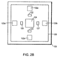
- Figure 2B is a schematic top view of the imaging device of Figure 2A;
- Figure 3 is a schematic side view of an imaging device employing a scanned light source and fixed position detector, according to an illustrative embodiment of the invention
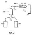
- Figure 4 is a schematic diagram depicting an imaging device employing a scanning device located remotely from a light source and a detector;
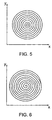
- Figure 5 depicts a pattern for a circular type of image scan, according to an illustrative embodiment of the invention
- Figure 6 depicts a pattern for a spiral type of image scan, according to an alternative illustrative embodiment of the invention.
- Figure 7A depicts an image pattern used as a test pattern, according to an illustrative embodiment of the invention.
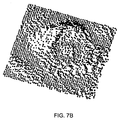
- Figure 7B depicts the image pattern of Figure 7A as the image is seen by a single pixel scanning camera, according to an illustrative embodiment of the invention
- Figure 7C depicts the image pattern of Figure 7B as an amplitude color map, according to an illustrative embodiment of the invention.
- Figure 8A is another illustrative scan of an image drawn on a piece of paper.
- Figure 8B is a scan of the same image of Figure 8A with the addition of a tab to show orientation.
- the invention in one embodiment, is directed to a miniature imaging device.
- the imaging device is located in the tip of an elongate sheath such as a catheter.
- the sheath may be inserted into a human body to observe images of target tissue.
- the imaging device of the invention is employed where conventional endoscopes are too large to be useful.
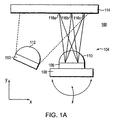
- FIG. 1A is a schematic diagram depicting an imaging device 100 employing a scanned detector, according to an illustrative embodiment of the invention.
- the imaging device 100 includes a fixedly mounted light source 102 and a scanned photo-sensor assembly 104.
- the scanned photo-sensor assembly 104 includes a photodiode 106 mounted on a scanning device 108 adapted to move along two axes (x,y).
- the imaging device 100 also includes a wide angle lens 112 mounted relative to the light source 102 and adapted to focus light from the light source 102 onto an entire target 114.
- the scanning device 108 synchronously scans the photodiode 106 to receive light energy from each of a plurality of locations, such as the locations 116a-116c, on the target 114.
- a focussing lens 110 located relative to the photodiode 106 limits the light energy from the target from impinging on the photodiode 106. More particularly, the focussing lens 110 allows substantially only light from a particular one of the plurality of scanned target locations to impinge on the photodiode at any one time.
- the scanning device 100 digitizes the outputs from the photodiode 106 for synchronously captured images for each of the plurality of scanned locations on the target 114 to generate a high quality image of the target 114.
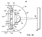
- Figure 1B is a schematic side view of an imaging device 120 employing a fixed position light source and a scanned detector of the type illustrated in Figure 1A.
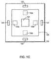
- Figure 1C is a schematic top view of the imaging device of Figure 1B.
- the imaging device 120 includes four light source assemblies 122, 123, 125 and 127; a photo-sensor assembly 124, a platform 126; a base 128, a pivot 130; x-axis actuators 132a and 132b; and y-axis actuators 133a and 133b, all located in the end 134 of an elongated sheath 139.
- the light source assemblies 122, 123, 125 and 127 are all fixedly mounted to a front face of the base 128.
- Each of the light source assemblies include an LED and a wide angle lens adapted for illuminating the target 136. More specifically, the light source assembly 122 includes an LED 122a and a wide angle focussing lens 122b.
- the light source assembly 123 includes an LED 123a and a wide angle focussing lens 123b; the light source assembly 125 includes an LED and a wide angle focussing lens; and the light source assembly 127 includes an LED and a wide angle focussing lens.
- Each LED is also powered by an LED power wire (e. g., 121a and 121 b).
- the light source assemblies 122, 123, 125 and 127 may illuminate the target 136 with any frequency of light, either concurrently or in a sequenced fashion.
- the light source assemblies 122, 123, 125 and 127 may illuminate the target 136 with white light for black and white image generation, and sequenced red, green and blue light, for color image generation.
- any other combination of wavelengths may be employed without deviating from the scope of the invention.
- the light source assemblies illuminate the target 136 with infrared light.
- each of the light source assemblies are mounted at an angle relative to the plane of the platform 126.
- the photo-sensor assembly 124 fixedly mounts on a platform 126.
- the platform 126 in turn, movably mounts the base 128 by way of a universal pivot joint 130.
- the universal pivot joint 130 enables the platform 126 to move in both the x and y-axes.
- the actuators 132a, 132b, 133a and 133b actuate the movement of the platform 126 with respect to the base 128. More particularly, the actuators 132a and 132b actuate the platform 126 along the x-axis and the actuators 133a and 133b actuate the platform 126 along the y-axis.
- the actuators are processor controlled.
- the actuators are electromagnetic.
- the actuators may be MEMs or piezoelectric actuators.
- Control signals are transmitted to the actuators 132a, 132b, 133a and 133b via scan control wires (e.g., 131a and 131b).
- the actuators 132a, 132b, 133a and 133b actuate the platform 126 in a predefined pattern (e.g., spiral, circle, raster scan or the like) to scan the target 136 to enable the photo-sensor assembly 124 to detect light energy from each of a plurality of locations on the target 136.
- the detected light may be, for example, fluorescent or reflected light and may be from anywhere in the spectrum, including visible and infrared.
- the actuators 132a, 132b,133a and 133b are pulsed to cause the platform 126 to move.
- the actuators are operated at resonance to reduce the power necessary to actuate the platform.
- the photo-sensor assembly 124 includes a photo-sensor 124a (preferably a single photo-diode) and a focussing lens and/or aperture 124b.
- the focussing lens or aperture 124b limits the amount of light energy from the target allowed to impinge on the photo-sensor 124a.
- the lens/aperture 124b allows only the light energy from one target location at a time to impinge on the photo-sensor 124a.
- the photo-sensor assembly 124 includes a mask on the photo-sensor 124a to further narrow the field of view (i.e., the selectivity).
- the lens is a fixed focal length converging lens.
- the lens is a gradient index lens.
- the end 134 of the elongated sheath 139 forms or includes a lens 140 for assisting in providing light from the source assemblies to the target 136 and/or focussing light energy from the target 136 back to the photo-sensor 124a.
- the illustrative imaging device 120 synchronizes the motion with the capture circuitry and digitizes the output from the photo-sensor 124a for each of the plurality of locations (e.g., 138) on the target 136 to generate an image of the target 136.
- the illustrative imaging device is about one millimeter square in size and provides about one hundred micron resolution.
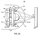
- Figures 2A and 2B depict an alternative embodiment 200 of the invention, wherein both the light source assemblies 122, 123, 125 and 127, and the photo-sensor assembly 124 are mounted on the platform 126 and can thus be directed at each of a plurality of locations on the target 136.
- the light source assembly lenses e.g., 122b and 123b
- the embodiment of Figures 2A and 2B operates in essentially the same fashion as the embodiment of Figures 1B and 1C.
- FIG 3 is a schematic side view of an imaging device 300 employing a scanned light source and fixed position detector, according to an illustrative embodiment of the invention.
- the light source assembly 122 is fixedly mounted on the platform 126.
- the platform 126 is movably mounted to the base 128 by way of the universal pivot 130 and actuated by the x-axis actuators 132a and 132b and the y-axis actuators.
- the photo-sensor assembly 124 is fixedly mounted on the base 128 at a location adjacent to the platform 126.
- the light source assembly 122 employs a fixed focal length lens 122b and the photo-sensor assembly 124 employs a wide angle lens 124b.
- the actuators actuate the platform 126 along the x- and y-axes in a predefined pattern (e.g., spiral, circle, raster scan or the like) to scan the target 136 to enable the light source assembly 122 to illuminate discretely each of a plurality of locations on the target 136 with, for example, white light for black and white image generation, or sequenced red, green and blue light, for color image generation.
- a predefined pattern e.g., spiral, circle, raster scan or the like
- the light source assembly 122 to illuminate discretely each of a plurality of locations on the target 136 with, for example, white light for black and white image generation, or sequenced red, green and blue light, for color image generation.
- the photo-sensor assembly 124 includes a photo-sensor 124a (preferably a single photo-diode) and a wide angle lens 124b.
- the lens allows substantially all of the light energy from the target 136 resulting from the light from the source assembly 122 to impinge on the photo-sensor 124a.
- the sensor device of Figure 3 By synchronously scanning the light source discretely over each of a plurality of locations on the target 136 and digitizing the output from the photo-sensor 124a for each of the plurality of locations, the sensor device of Figure 3 generates an image of the target 136.
- a lens such as the lens 140
- the reduced image may be scanned. In this way, the necessary excursion of the platform 126 and the scan time can be reduced.
- Figures 5 depicts a circular scanning pattern according to an illustrative embodiment of the invention.
- the image is acquired by moving the scanning device such that the scan produces a circular pattern with increasing diameter.
- the diameter increases until the end of the viewing area is reached.
- the scanned spot does not have to return to the center for the next frame.
- the illustrative imaging device of the invention acquires the data differently from that of the increasing diameter circle.
- the data is now acquired using a circular pattern with a decreasing diameter until the center of the imaging area is reached.
- odd numbered frames use the increasing diameter scan
- even numbered frames use the decreasing diameter scan.
- the scanning device of the invention digitizes the information appropriately based on the phase of the scan pattern (i.e., increasing or decreasing diameter).
- the acquired data is essentially in polar coordinates (r, ⁇ ).
- the polar coordinates can be converted to Cartesian coordinates for image reconstruction.
- Figure 6 depicts a spiral scan pattern according to another illustrative embodiment of the invention. According to other illustrative embodiments, polygonal scanning patterns, such as square scanning patterns are employed. It should be noted that any scanning pattern may be used without deviating from the scope of the invention.
- Figure 7A depicts an image that was scanned with an actual device constructed in accord with the principles of the invention.
- Figure 7B depicts the raw data in three-dimensional perspective corresponding to the image of Figure 7A and generated by an illustrative embodiment of the invention employing a single pixel photo-sensor.
- Figure 7C is amplitude color map corresponding to the image of Figure 7A and generated by an illustrative embodiment of the invention employing a single pixel photo-sensor.
- Figure 8A depicts another example of a scanned image generated by an illustrative embodiment of the invention. In Figure 8A, dimensions are shown on the x- and y-axes in millimeters.
- Figure 8B depicts another example of a scanned image, wherein the image includes a tab to show orientation. In Figure 8B, dimensions are shown along the x-axis in millimeters.
- the invention provides a photo-sensor device that is inexpensive to manufacture and smaller than the current technology.
- the invention employs a single miniature detector as opposed to an array of detectors, or bundles of fibers.
- One problem solved by the invention is that it can go into areas of the human body that an endoscope cannot. Additionally, since the device of the invention is inexpensive to make, it can be disposable. Additionally, the devices of the illustrative embodiments may be employed with any available display technology.
Landscapes
- Health & Medical Sciences (AREA)
- Life Sciences & Earth Sciences (AREA)
- Surgery (AREA)
- Engineering & Computer Science (AREA)
- Optics & Photonics (AREA)
- Physics & Mathematics (AREA)
- Biomedical Technology (AREA)
- Public Health (AREA)
- Biophysics (AREA)
- Pathology (AREA)
- Radiology & Medical Imaging (AREA)
- Veterinary Medicine (AREA)
- Nuclear Medicine, Radiotherapy & Molecular Imaging (AREA)
- Heart & Thoracic Surgery (AREA)
- Medical Informatics (AREA)
- Molecular Biology (AREA)
- Animal Behavior & Ethology (AREA)
- General Health & Medical Sciences (AREA)
- Multimedia (AREA)
- Signal Processing (AREA)
- Microelectronics & Electronic Packaging (AREA)
- Image Input (AREA)
- Microscoopes, Condenser (AREA)
- Endoscopes (AREA)
- User Interface Of Digital Computer (AREA)
- Peptides Or Proteins (AREA)
- Investigating, Analyzing Materials By Fluorescence Or Luminescence (AREA)
Abstract
Description
- This application is based on prior copending provisional patent application Ser. No. 60/347,391, filed on January 9, 2002, the benefit of the filing date of which is hereby claimed under 35 U.S.C. § 119(e).
- This invention relates to imaging devices. More particularly, in one embodiment, the invention is directed to a miniature imaging device and related methods.
- Spectral analysis of living tissue can be used to detect various forms of cancer and other types of diseases. In spectral analysis, light illuminates a tissue region under examination and a light detector detects optical properties of the illuminated tissue region by measuring light energy modified by its interaction with the tissue region in a pre-determined frequency and amplitude domain. Optical properties include absorption, luminescence, fluorescence, frequency and time domain response to various materials injected to the tissue region and other electromagnetic responses. Diseased tissue may be identified by comparing a spectrum obtained to spectra of normal tissue obtained under the same controlled conditions.
- Traditional image sensors include a two dimensional array of photo-detectors (pixels) that are accessed individually by electronics on the same chip, or external to the chip. A black and white image is formed by digitizing the amplitude of each pixel, which creates a gray scale. Color images function in a similar manner, but employ complex algorithms to compute the color. One common color sensor has a color mask that is placed on the image sensor. The color mask is a light filter that allows only certain light wavelengths to penetrate and reach the detector. Then, by comparing amplitudes of adjacent pixels, the color is calculated.
- One disadvantage of conventional image sensors is size due to the number of pixels (photo-detectors) required to produce a quality image. Another disadvantage of conventional image sensors is the complex electronics involved in addressing each pixel (photo-detector).
- US 5,762,603 discloses a surgical/diagnostic imaging device for use in interabdominal, interthoracic, and other surgical and diagnostic procedures including an image sensor pivotally mounted at the distal end of a support. In use, the image sensor and support are contained within a disposable sterile sheath, and the distal portion of the sheath is inserted into the patient through an incision. The imaging device includes actuators to move the image sensor in elevation and azimuth.
- US 5,159,446 discloses an electronic endoscope system comprising an electronic endoscope provided with an elongate and flexible insert section, an illuminating light emitting means for transmitting an illuminating light fed from outside and emitting it from an illuminating window of a distal end component of said insert section, an objective optical system provided in the distal and component of said insert section, an imaging means for photoelectrically converting an optical image based on said objective optical system and a first connector connected to a cable connected with said imaging means, an electric operating means for electrically performing at least one of an operation of bending a bendable portion provided in said insert section, an operation of advancing and retreating movement of said insert section in the axial direction of said insert section and an operation of rotating said insert section around the axial direction of said insert section, a second connector connected to a cable connected with said electric operating means, a video signal processing unit provided with a first connector receptacle making said first connector connectable and processing a signal for said imaging means to produce a video signal, an electric driving means for at least one of a bending driving means for bending and driving said bendable portion, an advancing and retreating driving means for advancing and retreating moving said insert section in the axial direction of said insert section and a rotating driving means for rotating driving said insert section in response to the operation of said electric operating means; a controlling unit formed separately from said video signal processing unit, provided with a second connector receptacle making said second connector connectable and controlling said electric driving means in response to the operation of said electric operating means, a light source apparatus provided with a connector receptable making the connector of said illuminating light emitting means connectable and feeding said illuminating light, and a monitor means for displaying said video signal.
- FR 2,666,713 discloses a video device with a monitor specific to a camera capable of being miniaturised to a great extent. In the camera, the straight-line vibration of an optical fibre is accumulated with a rotation in order to cause this fibre to observe a whole surface, a lens focusing the image onto the said optical fibre. Provision is made for marking the amplitude of the vibration and the speed of the rotation of the camera so that the monitor imitates them in its scanning, the latter being therefore similar to the movement of the end of the optical fibre. The rotation here is brought about by that of a cable linking the camera to the monitor, or by a motor situated in the camera. The vibration is provided by an electromagnet or by a piezoelectric transducer supporting the optical fibre and making it possible to avoid marking its vibration by the precision of the latter.
- DE 100 41 878 discloses a scanning section which scans an examined object using low coherent light, and the light reflected from the examined object is detected using a photodetector. A formation unit outputs a tomogram signal specifying a tomogram of the examined object, based on the output of the photodetector. A generator generates a video signal, based on the tomogram signal and an image of examined object photographed by an image pick-up.
- US 5,241,170 discloses a fiber optic viewing device having in a first embodiment, a color-preserving image intensifier positioned at the viewing end thereof. In a second embodiment, an input light source is sequentially modulated through a cycle of wavelength sets. The resulting image is intensified and recolored by an output recoloring filter which is synchronized with the input light modulation. In yet another embodiment, a set of red, green and blue LEDs are sequentially modulated by a controller to provide input light. A CCD camera receives the resultant intensified image and converts it to video format. A video processor stores frames during a cycle of modulation and then integrates the frames for viewing in full color.
- It is an object of the invention to provide a sufficiently accurate imaging system. This object is solved by the subject-matter of the independent claims.
- In one embodiment, the invention combines a scanning system similar to a display-type raster scan with a single photodiode to create an image. By doing so, the invention provides an imaging device that is smaller than traditional imaging devices.
- According to one embodiment, the imaging device of the invention includes a light source unit, a photo-sensor and a scanning assembly. The light source unit is fixedly mounted in the first end of an elongated sheath and is adapted for illuminating a target. The photo-sensor is mounted on the scanning assembly, also located in the first end of the elongated sheath, and is adapted to detect light energy from the target. The scanning assembly scans the target to enable the photo-sensor to detect light energy from each of a plurality of locations on the target.
According to a further embodiment, the imaging device of the invention synchronously digitizes the output from the photo-sensor from each of the plurality of locations on the target to generate an image of the target. According to a further embodiment, the light source unit provides wide angle/divergent illumination. According to one embodiment, the light energy includes reflected light. According to another embodiment, the light energy contains fluorescent light. - According to another embodiment, the scanning assembly includes a platform movably mounted on a constant velocity pivot joint adapted for enabling the scanning assembly to scan the target with a photo-sensor in two directions. According to one embodiment, the scanning assembly is adapted to scan the target at a sweep frequency of greater than or equal to about 1kHz. According to a further embodiment, the scanning assembly is adapted to scan a target at a sweep frequency above about 5 kHz. According to a further embodiment, the scanning assembly is adapted to scan a target at a sweep frequency above about 10 kHz. According to a further embodiment, the scanning assembly is adapted to scan a target at a sweep frequency above about 15 kHz. According to another embodiment, the scanning assembly is adapted to completely scan the target at a scan frequency of greater than or equal to about 2 Hz. According to a further embodiment, the scanning assembly is adapted to completely scan a target at a scan frequency above about 5 Hz. According to a further embodiment, the scanning assembly is adapted to completely scan a target at a scan frequency above about 10 Hz. According to a further embodiment, the scanning assembly is adapted to completely scan a target at a scan frequency above about 20 Hz. According to a further embodiment, the scanning assembly is adapted to completely scan a target at a scan frequency above about 30 Hz. According to a further embodiment, the scanning assembly is adapted to completely scan a target at a scan frequency above about 40 Hz. According to a further embodiment, the scanning assembly is adapted to completely scan a target at a scan frequency above about 50 Hz. However, various sweep and scan frequencies may be employed without deviating from the scope of the invention.
According to a further embodiment, the scanning assembly includes electromagnetic actuators for controlling platform movement. According to an alternative embodiment, the scanning assembly includes piezoelectric actuators for controlling the platform movement. According to another alternative embodiment, the scanning assembly includes microelectronic machine (MEMS) actuators for controlling the platform movement. - According to one feature, the MEMS actuators are fabricated in silicon, which is also a common substrate material for both photo-sensors and lasers diodes. The photo-sensor and/or the laser diode may be fabricated directly on the MEMS actuator plate using standard semiconductor processing techniques. This reduces the need for bonding discrete parts to the scanning platform, with the advantage that it may reduce the overall mass of the platform, allowing for higher scan rates and lower drive power. According to a further embodiment, the photo-sensor is a single pixel photo-sensor.
- According to one embodiment, the imaging device includes an aperture oriented with respect to the photo-sensor and adapted for limiting light energy from the target from impinging on the photo-sensor. According to one feature, the aperture allows substantially only the light energy from one target location at a time to impinge on the photo-sensor. According to another feature, the aperture includes a fixed focal length lens.
- According to an alternative embodiment, the imaging device of the invention includes a light source unit, a photo-sensor and a scanning assembly, wherein both the light source unit and the photo-sensor are movably mounted on a scanning assembly in the first end of an elongated sheath. The light source illuminates the target as the scanning assembly scans a plurality of locations on the target. The photo-sensor synchronously captures the light energy from each of the scanned locations on the target. The imaging device of the invention then synchronously digitizes the output from the photo-sensor from each of the plurality of locations on the target to generate an image of the target.
- According to another alternative embodiment, the imaging device of the invention includes a light source unit, a photo-sensor and a scanning assembly, wherein the photo-sensor is fixedly mounted on a platform in the first end of an elongated sheath and the light source is movably mounted on a scanning assembly, also in the first end of the sheath. According to one feature of this embodiment, the scanning assembly scans the target to discretely illuminate each of a plurality locations on the target. According to a further feature, the photo-sensor synchronously captures the light energy from each of the illuminated locations. According to another feature the imaging device of the invention then digitizes the output from the photo-sensor from each location on the target to generate an image of the target.
- According to one embodiment, the light source employs one or more LEDs. According to another embodiment, the light source employs one or more laser diodes. In a further embodiment, the light source unit employs a fixed focal length lens to focus the light onto discrete locations of the target. According to a further embodiment, the photo-sensor employs a wide angle lens to capture light energy from each of the scanned locations on the target.
- According to a further embodiment, the first end of the elongated sheath forms a lens adapted for focussing the light from the light source on to each of the scanned locations on the target. According to another embodiment, the first end of the elongated sheath forms a lens adapted for focussing light energy from each of the scanned locations on the target back on to the photo-sensor.
- According to another embodiment, the invention provides a scanning system adapted for generating color images of a target According to one embodiment, the scanning system of the invention employs field sequenced color (e.g., red, blue, green) LEDs pulsed in sequence for each of the plurality of locations illuminated on the target to achieve a color image of the target. According to one preferred embodiment, the imaging devices and methods of the invention are particularly adapted for analysis of living tissue.
- The patent or application file contains at least one drawing executed in color. Copies of this patent or patent application publication with color drawings will be provided by the Office upon request and payment of the necessary fee.
- The foregoing and other objects of the invention and the various features thereof may be more fully understood from the following description when read together with the accompanying drawings in which like reference designations generally refer to the same or similar parts throughout the different views and in which the depicted components are not necessarily drawn to scale.
- Figure 1A is a schematic diagram depicting an imaging device employing a scanned detector, according to an illustrative embodiment of the invention;
- Figure 1B is a schematic side view of an imaging device employing a fixed position light source and a scanned detector, according to an illustrative embodiment of the invention;
- Figure 1C is a schematic top view of the imaging device of Figure 1B;
- Figure 2A is a schematic side view of an imaging device, employing a scanned light source and a scanned detector, according to an illustrative embodiment of the invention;
- Figure 2B is a schematic top view of the imaging device of Figure 2A;
- Figure 3 is a schematic side view of an imaging device employing a scanned light source and fixed position detector, according to an illustrative embodiment of the invention;
- Figure 4 is a schematic diagram depicting an imaging device employing a scanning device located remotely from a light source and a detector;
- Figure 5 depicts a pattern for a circular type of image scan, according to an illustrative embodiment of the invention;
- Figure 6 depicts a pattern for a spiral type of image scan, according to an alternative illustrative embodiment of the invention;
- Figure 7A depicts an image pattern used as a test pattern, according to an illustrative embodiment of the invention;
- Figure 7B depicts the image pattern of Figure 7A as the image is seen by a single pixel scanning camera, according to an illustrative embodiment of the invention;
- Figure 7C depicts the image pattern of Figure 7B as an amplitude color map, according to an illustrative embodiment of the invention;
- Figure 8A is another illustrative scan of an image drawn on a piece of paper; and
- Figure 8B is a scan of the same image of Figure 8A with the addition of a tab to show orientation.
- As described in summary above, the invention, in one embodiment, is directed to a miniature imaging device. In one embodiment, the imaging device is located in the tip of an elongate sheath such as a catheter. The sheath may be inserted into a human body to observe images of target tissue. According to one embodiment, the imaging device of the invention is employed where conventional endoscopes are too large to be useful.
- Figure 1A is a schematic diagram depicting an
imaging device 100 employing a scanned detector, according to an illustrative embodiment of the invention. As depicted, theimaging device 100 includes a fixedly mountedlight source 102 and a scanned photo-sensor assembly 104. The scanned photo-sensor assembly 104 includes aphotodiode 106 mounted on ascanning device 108 adapted to move along two axes (x,y). Theimaging device 100 also includes awide angle lens 112 mounted relative to thelight source 102 and adapted to focus light from thelight source 102 onto anentire target 114. Thescanning device 108 synchronously scans thephotodiode 106 to receive light energy from each of a plurality of locations, such as the locations 116a-116c, on thetarget 114. A focussinglens 110, located relative to thephotodiode 106 limits the light energy from the target from impinging on thephotodiode 106. More particularly, the focussinglens 110 allows substantially only light from a particular one of the plurality of scanned target locations to impinge on the photodiode at any one time. Subsequent to scanning the entire target or a region of interest, thescanning device 100 digitizes the outputs from thephotodiode 106 for synchronously captured images for each of the plurality of scanned locations on thetarget 114 to generate a high quality image of thetarget 114. - Figure 1B is a schematic side view of an
imaging device 120 employing a fixed position light source and a scanned detector of the type illustrated in Figure 1A. Figure 1C is a schematic top view of the imaging device of Figure 1B. Referring to Figures 1B and 1C, theimaging device 120 includes fourlight source assemblies sensor assembly 124, aplatform 126; abase 128, apivot 130; x-axis actuators 132a and 132b; and y-axis actuators 133a and 133b, all located in theend 134 of anelongated sheath 139. Thelight source assemblies base 128. Each of the light source assemblies include an LED and a wide angle lens adapted for illuminating thetarget 136. More specifically, thelight source assembly 122 includes anLED 122a and a wideangle focussing lens 122b. Similarly, thelight source assembly 123 includes anLED 123a and a wideangle focussing lens 123b; thelight source assembly 125 includes an LED and a wide angle focussing lens; and thelight source assembly 127 includes an LED and a wide angle focussing lens. Each LED is also powered by an LED power wire (e. g., 121a and 121 b). According to one illustrative embodiment, thelight source assemblies target 136 with any frequency of light, either concurrently or in a sequenced fashion. In one illustrative example, thelight source assemblies target 136 with white light for black and white image generation, and sequenced red, green and blue light, for color image generation. However, any other combination of wavelengths may be employed without deviating from the scope of the invention. In other embodiments, for particular applications, such as scans that need to penetrate blood, the light source assemblies illuminate thetarget 136 with infrared light. According to one feature of the illustrated embodiments, each of the light source assemblies are mounted at an angle relative to the plane of theplatform 126. Although the embodiment of Figures 1B and 1C depict four light source assemblies, any number may be employed, limited by size and power constraints. - The photo-
sensor assembly 124 fixedly mounts on aplatform 126. Theplatform 126, in turn, movably mounts the base 128 by way of a universal pivot joint 130. The universal pivot joint 130 enables theplatform 126 to move in both the x and y-axes. Theactuators platform 126 with respect to thebase 128. More particularly, theactuators platform 126 along the x-axis and theactuators platform 126 along the y-axis. In one embodiment, the actuators are processor controlled. According to one preferred embodiment, the actuators are electromagnetic. However, according to other embodiments, the actuators may be MEMs or piezoelectric actuators. Control signals are transmitted to theactuators - According to the illustrative embodiment, the
actuators platform 126 in a predefined pattern (e.g., spiral, circle, raster scan or the like) to scan thetarget 136 to enable the photo-sensor assembly 124 to detect light energy from each of a plurality of locations on thetarget 136. The detected light may be, for example, fluorescent or reflected light and may be from anywhere in the spectrum, including visible and infrared. In one embodiment, theactuators platform 126 to move. In a further embodiment, the actuators are operated at resonance to reduce the power necessary to actuate the platform. According to the illustrative embodiment, the photo-sensor assembly 124 includes a photo-sensor 124a (preferably a single photo-diode) and a focussing lens and/oraperture 124b. The focussing lens oraperture 124b limits the amount of light energy from the target allowed to impinge on the photo-sensor 124a. According to one feature, the lens/aperture 124b allows only the light energy from one target location at a time to impinge on the photo-sensor 124a. Optionally, the photo-sensor assembly 124 includes a mask on the photo-sensor 124a to further narrow the field of view (i.e., the selectivity). According to another feature, the lens is a fixed focal length converging lens. In one embodiment, the lens is a gradient index lens. According to another feature, theend 134 of theelongated sheath 139 forms or includes alens 140 for assisting in providing light from the source assemblies to thetarget 136 and/or focussing light energy from thetarget 136 back to the photo-sensor 124a. - According to a further feature, the
illustrative imaging device 120 synchronizes the motion with the capture circuitry and digitizes the output from the photo-sensor 124a for each of the plurality of locations (e.g., 138) on thetarget 136 to generate an image of thetarget 136. - According to one embodiment, the illustrative imaging device is about one millimeter square in size and provides about one hundred micron resolution.
- Figures 2A and 2B depict an
alternative embodiment 200 of the invention, wherein both thelight source assemblies sensor assembly 124 are mounted on theplatform 126 and can thus be directed at each of a plurality of locations on thetarget 136. Rather than the wide angle divergent lenses employed in the embodiment of Figures 1B and 1C, according to the illustrative embodiment of Figures 2A and 2B, the light source assembly lenses (e.g., 122b and 123b) are fixed focal length lenses that focus light from the light source assemblies to each of the plurality of locations being scanned on thetarget 136. Other than this difference, the embodiment of Figures 2A and 2B operates in essentially the same fashion as the embodiment of Figures 1B and 1C. - Figure 3 is a schematic side view of an
imaging device 300 employing a scanned light source and fixed position detector, according to an illustrative embodiment of the invention. According to the illustrative embodiment of Figure 3, thelight source assembly 122 is fixedly mounted on theplatform 126. As in the previous embodiments, theplatform 126 is movably mounted to thebase 128 by way of theuniversal pivot 130 and actuated by thex-axis actuators sensor assembly 124 is fixedly mounted on the base 128 at a location adjacent to theplatform 126. In this embodiment, thelight source assembly 122 employs a fixedfocal length lens 122b and the photo-sensor assembly 124 employs awide angle lens 124b. - According to the illustrative embodiment of Figure 3, the actuators actuate the
platform 126 along the x- and y-axes in a predefined pattern (e.g., spiral, circle, raster scan or the like) to scan thetarget 136 to enable thelight source assembly 122 to illuminate discretely each of a plurality of locations on thetarget 136 with, for example, white light for black and white image generation, or sequenced red, green and blue light, for color image generation. Although only one light source assembly is depicted in Figure 3 and as discussed above, any number of light source assemblies may be mounted on theplatform 126 without deviating from the scope of the invention. - According to the embodiment of Figure 3, the photo-
sensor assembly 124 includes a photo-sensor 124a (preferably a single photo-diode) and awide angle lens 124b. The lens allows substantially all of the light energy from thetarget 136 resulting from the light from thesource assembly 122 to impinge on the photo-sensor 124a. By synchronously scanning the light source discretely over each of a plurality of locations on thetarget 136 and digitizing the output from the photo-sensor 124a for each of the plurality of locations, the sensor device of Figure 3 generates an image of thetarget 136. - Although the above embodiments describe scanning the target directly, in alternative embodiments, a lens, such as the
lens 140, may be employed for image reduction. Then, the reduced image may be scanned. In this way, the necessary excursion of theplatform 126 and the scan time can be reduced. - Figures 5 depicts a circular scanning pattern according to an illustrative embodiment of the invention. By starting in the center of the imaging area of the target, the image is acquired by moving the scanning device such that the scan produces a circular pattern with increasing diameter. The diameter increases until the end of the viewing area is reached. The scanned spot does not have to return to the center for the next frame. Instead, the illustrative imaging device of the invention acquires the data differently from that of the increasing diameter circle. The data is now acquired using a circular pattern with a decreasing diameter until the center of the imaging area is reached. In one embodiment, odd numbered frames use the increasing diameter scan, while even numbered frames use the decreasing diameter scan. The scanning device of the invention digitizes the information appropriately based on the phase of the scan pattern (i.e., increasing or decreasing diameter). The acquired data is essentially in polar coordinates (r,θ). The polar coordinates can be converted to Cartesian coordinates for image reconstruction.
Figure 6 depicts a spiral scan pattern according to another illustrative embodiment of the invention. According to other illustrative embodiments, polygonal scanning patterns, such as square scanning patterns are employed. It should be noted that any scanning pattern may be used without deviating from the scope of the invention. - Figure 7A depicts an image that was scanned with an actual device constructed in accord with the principles of the invention. Figure 7B depicts the raw data in three-dimensional perspective corresponding to the image of Figure 7A and generated by an illustrative embodiment of the invention employing a single pixel photo-sensor. Figure 7C is amplitude color map corresponding to the image of Figure 7A and generated by an illustrative embodiment of the invention employing a single pixel photo-sensor. Figure 8A depicts another example of a scanned image generated by an illustrative embodiment of the invention. In Figure 8A, dimensions are shown on the x- and y-axes in millimeters. Figure 8B depicts another example of a scanned image, wherein the image includes a tab to show orientation. In Figure 8B, dimensions are shown along the x-axis in millimeters.
- As can be seen from the above illustrative embodiments, the invention provides a photo-sensor device that is inexpensive to manufacture and smaller than the current technology. In one embodiment, the invention employs a single miniature detector as opposed to an array of detectors, or bundles of fibers. One problem solved by the invention is that it can go into areas of the human body that an endoscope cannot. Additionally, since the device of the invention is inexpensive to make, it can be disposable. Additionally, the devices of the illustrative embodiments may be employed with any available display technology.
Claims (48)
- An imaging device insertible into a human body comprising:a sheath (139);a light source (122) mounted on a first platform (126) and disposed within the sheath (139) for illuminating at least a portion of a target region (136);a single pixel photo-sensor (124) mounted on a second platform (128) and disposed within the sheath (139) for sensing light energy received from at least a portion (138) of the target region (136); anda movable assembly (132a, 132b, 133a, 133b) adapted to move the first platform (126) in at least two dimensions relative to the second platform (128) to scan the target region (136) to enable the photo-sensor (124) to detect light energy from each of a plurality of locations on the target region (136).
- The imaging device of claim 1 further comprising a plurality of light sources (122, 123, 125, 127) disposed for illuminating at least a portion (138) of a target region (136).
- The imaging device of claim 2 wherein at least one of the plurality of light sources (122, 123, 125, 127) is an LED or a laser diode.
- The imaging device of claim 1 wherein the sheath (139) further comprises an aperture adapted for focussing light on the target region (136).
- The imaging device of claim 4 wherein the aperture comprises a divergent lens (140) or a fixed focal length lens (140).
- The imaging device of claim 1 wherein the light source (122) provides reflected light or fluorescent light.
- The imaging device of claim 1 wherein the sheath 139 further comprises an aperture adapted for focussing light energy received from each of a plurality of illuminated locations (138) of the target region (136) onto the photo sensor (124).
- The imaging device of claim 7 wherein the aperture comprises a fixed focal length lens (140) or a diverging lens (140).
- The imaging device of claim 1 wherein the movable assembly (132a, 132b, 133a, 133b) comprises an electromagnetic material.
- The imaging device of claim 1 wherein the movable assembly (132a, 132b, 133a, 133b) further comprises an electromagnetic actuator, a microelectronic machine type actuator or a piezoelectric actuator coupled to the movable platform (126) for controlling movement of the first platform (126).
- The imaging device of claim 1 wherein the imaging device is disposable.
- The imaging device of claim 1 wherein the movable assembly (132a, 132b, 133a, 133b) moves the first platform (126) relative to the sheath (139) in a predetermined scanning pattern to image separately each of a plurality of locations (138) of the target region (136) to form an image of the target region (136).
- The imaging device of claim 1 wherein the light source (122) comprises a plurality of lighting elements (122, 123, 125, 127) mounted on the first platform (128).
- The imaging device of claim 13, wherein the first platform (126) extends substantially along a plane and wherein of the lighting elements (122, 123, 125, 127) is angled with respect to the plane.
- The imaging device of claim 1 or 12 further comprising a lens (124b) mounted over the photo-sensor (124).
- A method for imaging a target region (136) inside a human body comprising:positioning a sheath (139) relative to the target region (126), the sheath (139) including therein a light source (122), a single pixel photo-sensor (124) and a movable assembly (132a, 132b, 133a, 133b) for moving the photo-sensor (124) relative to the light source (122);illuminating at least a portion (138) of the target region (136) inside with the light source (122);sensing energy from the light source (122) after reflection from a first portion (138) of the target region (136) with the photo-sensor (124);operating the movable assembly (132a, 132b, 133a, 133b) to move the photo-sensor (124);sensing energy from the light source (122) after reflection from a second portion (138) of the target region (136); andrepeating the operating and sensing steps to scan the target region (136) to enable the photo-sensor (124) to detect light energy from each of the portions (138) on the target region (136) to form an image of the target region (136).
- The method for imaging of claim 16 further comprising: scanning the target region (136) by moving the photo-sensor (124) in at least two dimensions.
- The method of imaging of claim 17 further comprising: mounting the movable assembly (132a, 132b, 133a, 133b) on a constant velocity pivot joint (130) adapted for moving the photo-sensor (124) in two dimensions.
- The method of imaging of claim 17 further comprising: scanning the target region (136) at a sweep frequency of greater than or equal to about 1 kHz.
- The method of imaging of claim 17 further comprising: scanning the target region (136) at a rate of greater than or equal to about 2 Hz.
- The method of imaging of claim 16 further comprising: providing a light source (122) of field sequenced color LEDs pulsed in sequence for each of a plurality of locations (138) of the target region (136); and scanning the target region (136) by moving the photo-sensor (124) in at least two dimensions to generate a color image of the target region (136).
- The method of imaging of claim 16 further comprising: scanning the target region (136) by moving the photo-sensor (124) in two dimensions to create a raster scan or a circular scan of the target region (136).
- The method for imaging of claim 16 further comprising: synchronously digitizing the sensed energy received by the photo-sensor (124) from each of a plurality of locations (138) of the target region (136) to generate an image of the target region (136).
- The method for imaging of claim 16 further comprising: synchronously scanning light from the light source (122) onto each of a plurality of locations (138) on the target region (136).
- An imaging device insertible into a human body comprising:a sheath (139);a light source (122) mounted on a first platform (126) and disposed within the sheath (139) for illuminating at least a portion of a target region (136);a single pixel photo-sensor (124) mounted on a second platform (128) and disposed within the sheath (139) for sensing light energy received from at least a portion (138) of the target region (139); anda movable assembly (132a, 132b, 133a, 133b) adapted to move the second platform (128) in at least two dimensions relative to the first platform (126) to scan the target region (136) to enable the photo-sensor (124) to detect-light energy from each of a plurality of locations on the target region (136).
- The imaging device of claim 25 further comprising a plurality of light sources (122, 123, 125, 127) disposed for illuminating at least a portion (138) of a target region (136).
- The imaging device of claim 26 wherein at least one of the plurality of light sources (122, 123, 125, 127) is an LED or a laser diode.
- The imaging device of claim 25 wherein the sheath (139) further comprises an aperture adapted for focussing light on the target region (136).
- The imaging device of claim 28 wherein the aperture comprises a divergent lens (140) or a fixed focal length lens (140).
- The imaging device of claim 25 wherein the light source (122) provides reflected light or fluorescent light.
- The imaging device of claim 25 wherein the sheath (139) further comprises an aperture adapted for focussing light energy received from each of a plurality of illuminated locations (138) of the target region (136) onto the photo-sensor (124).
- The imaging device of claim 31 wherein the aperture comprises a fixed focal length lens (140) or a diverging lens (140).
- The imaging device of claim 25 wherein the movable assembly (132a, 132b, 133a, 133b) comprises an electromagnetic material.
- The imaging device of claim 25 wherein the movable assembly (132a, 132b, 133a, 133b) further comprises an electromagnetic actuator, a microelectronic machine type actuator or a piezoelectric actuator coupled to the movable platform (126) for controlling movement of the second platform (128).
- The imaging device of claim 25 wherein the imaging device is disposable.
- The imaging device of claim 25 wherein the movable assembly (132a, 132b, 133a, 133b) moves the second platform (128) relative to the sheath (139) in a predetermined scanning pattern to image separately each of a plurality of locations (138) of the target region (136) to form an image of the target region (136).
- The imaging device of claim 25 wherein the light source (122) comprises a plurality of lighting elements (122, 123, 125, 127) mounted on the first platform (126).
- The imaging device of claim 37, wherein the first platform (126) extends substantially along a plane and wherein each of the lighting elements (122, 123, 125, 127) is angled with respect to the plane.
- The imaging device of claim 1 or 36 further comprising a lens (124b) mounted over the photo-sensor (124) allowing only light reflected from a single location (138) of the target area (136) to be received by the photo-sensor (124).
- A method for imaging a target region (136) inside a human body comprising:positioning a sheath (139) relative to the target region (126), the sheath (139) including therein a light source (122), a single pixel photo-sensor (124) and a movable assembly (132a, 132b, 133a, 133b) for moving the light source (122) relative to the photo sensor (124);illuminating at least a portion (138) of the target region (136) inside with the light source (122);sensing energy from the light source (122) after reflection from a first portion (138) of the target region (136) with the photo-sensor (124);operating the movable assembly (132a, 132b, 133a, 133b) to move the light source (122) ;sensing energy from the light source (122) after reflection from a second portion (136) of the target region (136); andrepeating the operating and sensing steps to scan the target region (136) to enable the photo-sensor (124) to detect light energy from each of the portions (138) on the target region (136) to form an image of the target region (136).
- The method for imaging of claim 40 further comprising: scanning the target region (136) by moving the light source (122) in at least two dimensions.
- The method of imaging of claim 41 further comprising: mounting the movable assembly (132a, 132b, 133a, 133b) on a constant velocity pivot joint (130) adapted for moving the light source (122) in two dimensions.
- The method of imaging of claim 41 further comprising: scanning the target region (136) at a sweep frequency of greater than or equal to about 1 kHz.
- The method of imaging of claim 41 further comprising: scanning the target region (136) at a rate of greater than or equal to about 2 Hz.
- The method of imaging of claim 40 further comprising: providing a light source (122) of field sequenced color LEDs pulsed in sequence for each of a plurality of locations (138) of the target region (136); and scanning the target region (136) by moving the light source (122) in at least two dimensions to generate a color image of the target region (136).
- The method of imaging of claim 40 further comprising: scanning the target region (136) by moving the light source (122) in two dimensions to create a raster scan or a circular scan of the target region (136).
- The method for imaging of claim 40 further comprising: synchronously digitizing the sensed energy received by the photo-sensor (124) from each of a plurality of locations (138) of the target region (136) to generate an image of the target region (136).
- The method for imaging of claim 40 further comprising: synchronously scanning light from the light source (122) onto each of a plurality of locations (138) on the target region (136).
Applications Claiming Priority (5)
| Application Number | Priority Date | Filing Date | Title |
|---|---|---|---|
| US34739102P | 2002-01-09 | 2002-01-09 | |
| US347391P | 2002-01-09 | ||
| US10/195,603 US8423110B2 (en) | 2002-01-09 | 2002-07-15 | Imaging device and related methods |
| US195603 | 2002-07-15 | ||
| PCT/US2002/040035 WO2003061275A2 (en) | 2002-01-09 | 2002-12-13 | Imaging device and related methods |
Publications (2)
| Publication Number | Publication Date |
|---|---|
| EP1464165A2 EP1464165A2 (en) | 2004-10-06 |
| EP1464165B1 true EP1464165B1 (en) | 2007-04-25 |
Family
ID=26891129
Family Applications (1)
| Application Number | Title | Priority Date | Filing Date |
|---|---|---|---|
| EP02806459A Expired - Lifetime EP1464165B1 (en) | 2002-01-09 | 2002-12-13 | Imaging device and related methods |
Country Status (8)
| Country | Link |
|---|---|
| US (1) | US8423110B2 (en) |
| EP (1) | EP1464165B1 (en) |
| JP (1) | JP4672260B2 (en) |
| AT (1) | ATE360953T1 (en) |
| AU (1) | AU2002357230A1 (en) |
| CA (1) | CA2472012A1 (en) |
| DE (1) | DE60219824T2 (en) |
| WO (1) | WO2003061275A2 (en) |
Cited By (1)
| Publication number | Priority date | Publication date | Assignee | Title |
|---|---|---|---|---|
| EP4000503A4 (en) * | 2019-07-15 | 2023-08-30 | Medivel Bio Co., Ltd. | Image acquisition device |
Families Citing this family (83)
| Publication number | Priority date | Publication date | Assignee | Title |
|---|---|---|---|---|
| ATE404114T1 (en) | 2001-06-18 | 2008-08-15 | Given Imaging Ltd | SWALLOWABLE IN-VIVO CAPSULE WITH A CIRCUIT BOARD HAVING RIGID AND FLEXIBLE SECTIONS |
| IL159616A0 (en) | 2001-06-28 | 2004-06-01 | Given Imaging Ltd | In vivo imaging device with a small cross sectional area |
| JP4018631B2 (en) * | 2001-08-28 | 2007-12-05 | シーメンス アクチエンゲゼルシヤフト | Scanning camera |
| JP4363843B2 (en) | 2002-03-08 | 2009-11-11 | オリンパス株式会社 | Capsule endoscope |
| JP2003260025A (en) * | 2002-03-08 | 2003-09-16 | Olympus Optical Co Ltd | Capsule endoscope |
| US20030216622A1 (en) * | 2002-04-25 | 2003-11-20 | Gavriel Meron | Device and method for orienting a device in vivo |
| US7662094B2 (en) * | 2002-05-14 | 2010-02-16 | Given Imaging Ltd. | Optical head assembly with dome, and device for use thereof |
| AU2003264858A1 (en) * | 2002-09-30 | 2004-04-19 | Given Imaging Ltd. | Reduced size imaging device |
| AU2003269438A1 (en) * | 2002-09-30 | 2004-04-19 | Given Imaging Ltd. | In-vivo sensing system |
| US20080045788A1 (en) * | 2002-11-27 | 2008-02-21 | Zvika Gilad | Method and device of imaging with an in vivo imager |
| FR2849218B1 (en) * | 2002-12-20 | 2005-03-04 | Mauna Kea Technologies | CONFOCAL OPTICAL HEAD, IN PARTICULAR MINIATURE, INTEGRATED SCANNING AND CONFOCAL IMAGING SYSTEM IMPLEMENTING SAID HEAD |
| WO2004058041A2 (en) * | 2002-12-26 | 2004-07-15 | Given Imaging Ltd. | Immobilizable in vivo sensing device |
| JP2004275542A (en) * | 2003-03-17 | 2004-10-07 | Olympus Corp | Capsule type endoscope |
| US7316930B1 (en) | 2003-04-21 | 2008-01-08 | National Semiconductor Corporation | Use of vertically stacked photodiodes in a gene chip system |
| EP1618835B1 (en) * | 2003-04-25 | 2013-08-28 | Olympus Corporation | Capsule endoscope and capsule endoscope system |
| US7319782B2 (en) * | 2003-06-18 | 2008-01-15 | Hogan Josh N | Real-time imaging and analysis system |
| US7044908B1 (en) * | 2003-07-08 | 2006-05-16 | National Semiconductor Corporation | Method and system for dynamically adjusting field of view in a capsule endoscope |
| US7066879B2 (en) * | 2003-07-15 | 2006-06-27 | The Trustees Of Columbia University In The City Of New York | Insertable device and system for minimal access procedure |
| US20050027164A1 (en) * | 2003-07-29 | 2005-02-03 | Scimed Life Systems, Inc. | Vision catheter |
| US20050027163A1 (en) * | 2003-07-29 | 2005-02-03 | Scimed Life Systems, Inc. | Vision catheter |
| US7399274B1 (en) * | 2003-08-19 | 2008-07-15 | National Semiconductor Corporation | Sensor configuration for a capsule endoscope |
| US8702597B2 (en) * | 2003-12-31 | 2014-04-22 | Given Imaging Ltd. | Immobilizable in-vivo imager with moveable focusing mechanism |
| US7625338B2 (en) * | 2003-12-31 | 2009-12-01 | Given Imaging, Ltd. | In-vivo sensing device with alterable fields of view |
| WO2005082226A1 (en) * | 2004-02-27 | 2005-09-09 | Olympus Corporation | Endoscope |
| US7088239B2 (en) * | 2004-03-02 | 2006-08-08 | Vann Basinger | Method and apparatus for all-purpose, automatic remote utility meter reading, utility shut off, and hazard warning and correction |
| US7273452B2 (en) * | 2004-03-04 | 2007-09-25 | Scimed Life Systems, Inc. | Vision catheter system including movable scanning plate |
| US20050288555A1 (en) * | 2004-06-28 | 2005-12-29 | Binmoeller Kenneth E | Methods and devices for illuminating, vievwing and monitoring a body cavity |
| RU2007110632A (en) * | 2004-09-03 | 2008-10-10 | Страйкер Ги Лтд. (Il) | OPTICAL HEAD FOR ENDOSCOPE |
| US20090281389A1 (en) * | 2004-12-30 | 2009-11-12 | Iddan Gavriel J | Device, system, and method for adaptive imaging |
| DE102005015522A1 (en) | 2005-04-04 | 2006-10-05 | Karl Storz Gmbh & Co. Kg | Intracorporal probe for human or animal body, has image acquisition unit designed for optical admission of area outside probe, and movably held within housing in order to change movement of admission area |
| JP4528216B2 (en) * | 2005-06-29 | 2010-08-18 | オリンパスメディカルシステムズ株式会社 | Endoscope |
| GB0517948D0 (en) * | 2005-09-03 | 2005-10-12 | Keeler Ltd | Imaging apparatus, portable image capture device and method of assembling composite images from component images |
| US7896805B2 (en) * | 2005-11-23 | 2011-03-01 | Given Imaging Ltd. | In-vivo imaging device and optical system thereof |
| US9320417B2 (en) | 2005-12-29 | 2016-04-26 | Given Imaging Ltd. | In-vivo optical imaging device with backscatter blocking |
| US20070167834A1 (en) * | 2005-12-29 | 2007-07-19 | Amit Pascal | In-vivo imaging optical device and method |
| US7701565B2 (en) * | 2006-04-10 | 2010-04-20 | Avago Technologies Ecbu Ip (Singapore) Pte. Ltd. | Optical navigation system with adjustable operating Z-height |
| EP2020897B1 (en) * | 2006-05-09 | 2015-04-29 | Koninklijke Philips N.V. | Imaging system for three-dimensional imaging of the interior of an object |
| US20070270651A1 (en) * | 2006-05-19 | 2007-11-22 | Zvika Gilad | Device and method for illuminating an in vivo site |
| US9079762B2 (en) | 2006-09-22 | 2015-07-14 | Ethicon Endo-Surgery, Inc. | Micro-electromechanical device |
| US7713265B2 (en) | 2006-12-22 | 2010-05-11 | Ethicon Endo-Surgery, Inc. | Apparatus and method for medically treating a tattoo |
| US8801606B2 (en) | 2007-01-09 | 2014-08-12 | Ethicon Endo-Surgery, Inc. | Method of in vivo monitoring using an imaging system including scanned beam imaging unit |
| US8273015B2 (en) | 2007-01-09 | 2012-09-25 | Ethicon Endo-Surgery, Inc. | Methods for imaging the anatomy with an anatomically secured scanner assembly |
| US20100188443A1 (en) * | 2007-01-19 | 2010-07-29 | Pixtronix, Inc | Sensor-based feedback for display apparatus |
| US8216214B2 (en) | 2007-03-12 | 2012-07-10 | Ethicon Endo-Surgery, Inc. | Power modulation of a scanning beam for imaging, therapy, and/or diagnosis |
| JP5118867B2 (en) * | 2007-03-16 | 2013-01-16 | オリンパス株式会社 | Endoscope observation apparatus and operation method of endoscope |
| US7995045B2 (en) | 2007-04-13 | 2011-08-09 | Ethicon Endo-Surgery, Inc. | Combined SBI and conventional image processor |
| US8626271B2 (en) | 2007-04-13 | 2014-01-07 | Ethicon Endo-Surgery, Inc. | System and method using fluorescence to examine within a patient's anatomy |
| US8160678B2 (en) | 2007-06-18 | 2012-04-17 | Ethicon Endo-Surgery, Inc. | Methods and devices for repairing damaged or diseased tissue using a scanning beam assembly |
| US7982776B2 (en) | 2007-07-13 | 2011-07-19 | Ethicon Endo-Surgery, Inc. | SBI motion artifact removal apparatus and method |
| US9125552B2 (en) | 2007-07-31 | 2015-09-08 | Ethicon Endo-Surgery, Inc. | Optical scanning module and means for attaching the module to medical instruments for introducing the module into the anatomy |
| US7983739B2 (en) | 2007-08-27 | 2011-07-19 | Ethicon Endo-Surgery, Inc. | Position tracking and control for a scanning assembly |
| US7925333B2 (en) | 2007-08-28 | 2011-04-12 | Ethicon Endo-Surgery, Inc. | Medical device including scanned beam unit with operational control features |
| US7615729B2 (en) * | 2007-12-10 | 2009-11-10 | Aptina Imaging Corporation | Apparatus and method for resonant lens focusing |
| US8050520B2 (en) | 2008-03-27 | 2011-11-01 | Ethicon Endo-Surgery, Inc. | Method for creating a pixel image from sampled data of a scanned beam imager |
| US8332014B2 (en) | 2008-04-25 | 2012-12-11 | Ethicon Endo-Surgery, Inc. | Scanned beam device and method using same which measures the reflectance of patient tissue |
| CN102124392A (en) * | 2008-08-19 | 2011-07-13 | 罗姆股份有限公司 | Camera |
| JP5483917B2 (en) * | 2009-03-31 | 2014-05-07 | ローム株式会社 | Endoscope |
| US20100137684A1 (en) * | 2008-12-03 | 2010-06-03 | Hoya Corporation | Endoscope system with scanning function |
| US8516691B2 (en) | 2009-06-24 | 2013-08-27 | Given Imaging Ltd. | Method of assembly of an in vivo imaging device with a flexible circuit board |
| US9788731B2 (en) * | 2011-02-21 | 2017-10-17 | Jaywant Philip Parmar | Optical endoluminal far-field microscopic imaging catheter |
| AU2012253254B2 (en) | 2011-05-12 | 2016-12-15 | DePuy Synthes Products, Inc. | Image sensor with tolerance optimizing interconnects |
| US20120296163A1 (en) * | 2011-05-19 | 2012-11-22 | Tyco Healthcare Group Lp | Integrated visualization apparatus, systems and methods thereof |
| JP5997170B2 (en) * | 2011-10-03 | 2016-09-28 | Serendipity株式会社 | Imaging apparatus and rigid endoscope |
| US8749538B2 (en) | 2011-10-21 | 2014-06-10 | Qualcomm Mems Technologies, Inc. | Device and method of controlling brightness of a display based on ambient lighting conditions |
| US8948338B2 (en) | 2011-11-03 | 2015-02-03 | Medtronic Navigation, Inc. | Dynamically scanned X-ray detector panel |
| US9294667B2 (en) * | 2012-03-10 | 2016-03-22 | Digitaloptics Corporation | MEMS auto focus miniature camera module with fixed and movable lens groups |
| WO2014018951A1 (en) | 2012-07-26 | 2014-01-30 | Olive Medical Corporation | Ycbcr pulsed illumination scheme in a light deficient environment |
| AU2013295553B2 (en) | 2012-07-26 | 2017-10-19 | DePuy Synthes Products, Inc. | Continuous video in a light deficient environment |
| AU2013295565B2 (en) | 2012-07-26 | 2017-06-22 | DePuy Synthes Products, Inc. | Camera system with minimal area monolithic CMOS image sensor |
| US9188428B2 (en) * | 2012-08-07 | 2015-11-17 | Carl Zeiss Industrielle Messtechnik Gmbh | Coordinate measuring machine with selectively active white light sensor |
| US9183812B2 (en) | 2013-01-29 | 2015-11-10 | Pixtronix, Inc. | Ambient light aware display apparatus |
| JP5962533B2 (en) | 2013-02-13 | 2016-08-03 | ソニー株式会社 | Solid-state imaging device, driving method, and imaging apparatus |
| CN105228503B (en) | 2013-03-15 | 2017-11-07 | 德普伊新特斯产品公司 | Minimize the quantity of imaging sensor input/output and conductor in endoscopic applications |
| US9777913B2 (en) | 2013-03-15 | 2017-10-03 | DePuy Synthes Products, Inc. | Controlling the integral light energy of a laser pulse |
| US9641815B2 (en) | 2013-03-15 | 2017-05-02 | DePuy Synthes Products, Inc. | Super resolution and color motion artifact correction in a pulsed color imaging system |
| CA2906821A1 (en) | 2013-03-15 | 2014-09-18 | Olive Medical Corporation | Scope sensing in a light controlled environment |
| AU2014233190B2 (en) | 2013-03-15 | 2018-11-01 | DePuy Synthes Products, Inc. | Image sensor synchronization without input clock and data transmission clock |
| WO2015143453A1 (en) | 2014-03-21 | 2015-09-24 | Olive Medical Corporation | Card edge connector for an imaging sensor |
| CN105769249B (en) * | 2014-12-24 | 2019-06-11 | 珂纳医疗科技(苏州)有限公司 | Photoacoustic imaging endoscope |
| TWI667183B (en) * | 2017-08-03 | 2019-08-01 | 崴強科技股份有限公司 | Method of detecting feeding status and width of paper |
| JP7339949B2 (en) | 2018-01-04 | 2023-09-06 | アプライド メディカル リソーシーズ コーポレイション | Surgical simulation camera scope |
| US11533435B2 (en) * | 2018-04-06 | 2022-12-20 | Board Of Trustees Of Southern Illinois University | Multifunctional camera system for video assisted thoracic surgery |
| WO2020112500A1 (en) * | 2018-11-30 | 2020-06-04 | Verily Life Sciences Llc | Endoscopic systems including a multimode optical fiber and a machine learning classifier for interrogating a portion of a body |
Family Cites Families (105)
| Publication number | Priority date | Publication date | Assignee | Title |
|---|---|---|---|---|
| US31289A (en) * | 1861-02-05 | Adjusting coupling-link of railway-cars | ||
| US55462A (en) * | 1866-06-12 | Improved bed-bottom | ||
| US34110A (en) * | 1862-01-07 | Improvement in churns | ||
| US64341A (en) * | 1867-04-30 | Improvement in plane-ieons | ||
| USRE31289E (en) | 1978-10-16 | 1983-06-28 | Welch Allyn, Inc. | Color endoscope with charge coupled device and television viewing |
| US4265121A (en) | 1978-11-13 | 1981-05-05 | Litton Industrial Products, Inc. | High resolution ultrasound diagnostic apparatus |
| US4340307A (en) | 1980-07-07 | 1982-07-20 | Beckman Instruments, Inc. | Bichromatic spectrophotometer with wavelength reversal |
| US4803992A (en) * | 1980-10-28 | 1989-02-14 | Lemelson Jerome H | Electro-optical instruments and methods for producing same |
| US4510384A (en) * | 1981-08-17 | 1985-04-09 | National Research Development Corporation | Automatic focusing device with frequency weighted amplification |
| FR2526935A1 (en) * | 1982-05-14 | 1983-11-18 | Thomson Csf | METHOD AND DEVICE FOR SIMULTANEOUS MEASUREMENT OF GEOMETRIC CHARACTERISTICS OF AN OPTICAL FIBER |
| US4541272A (en) | 1983-05-13 | 1985-09-17 | Roland Bause | Electronically controlled fuel injection system |
| JPH0658457B2 (en) | 1984-04-13 | 1994-08-03 | オリンパス光学工業株式会社 | Endoscope device |
| JPH0648327B2 (en) * | 1984-07-28 | 1994-06-22 | オリンパス光学工業株式会社 | Endoscope objective lens |
| US5318024A (en) | 1985-03-22 | 1994-06-07 | Massachusetts Institute Of Technology | Laser endoscope for spectroscopic imaging |
| US5106387A (en) | 1985-03-22 | 1992-04-21 | Massachusetts Institute Of Technology | Method for spectroscopic diagnosis of tissue |
| US4718417A (en) | 1985-03-22 | 1988-01-12 | Massachusetts Institute Of Technology | Visible fluorescence spectral diagnostic for laser angiosurgery |
| JPH0658458B2 (en) | 1985-07-12 | 1994-08-03 | オリンパス光学工業株式会社 | Endoscope device |
| US5042494A (en) | 1985-11-13 | 1991-08-27 | Alfano Robert R | Method and apparatus for detecting cancerous tissue using luminescence excitation spectra |
| US4895156A (en) | 1986-07-02 | 1990-01-23 | Schulze John E | Sensor system using fluorometric decay measurements |
| JPS6340117A (en) | 1986-08-05 | 1988-02-20 | Anzai Sogo Kenkyusho:Kk | Image pickup device for wall in pipe |
| US4895431A (en) * | 1986-11-13 | 1990-01-23 | Olympus Optical Co., Ltd. | Method of processing endoscopic images |
| JPH07108284B2 (en) | 1986-12-26 | 1995-11-22 | オリンパス光学工業株式会社 | Extracorporeal observation device |
| US5001556A (en) | 1987-09-30 | 1991-03-19 | Olympus Optical Co., Ltd. | Endoscope apparatus for processing a picture image of an object based on a selected wavelength range |
| US4854302A (en) | 1987-11-12 | 1989-08-08 | Welch Allyn, Inc. | Video equipped endoscope with needle probe |
| US5051823A (en) | 1988-01-28 | 1991-09-24 | Fuji Optical Systems, Inc. | Dental instrument including laser device and electronic video dental camera |
| US5372138A (en) | 1988-03-21 | 1994-12-13 | Boston Scientific Corporation | Acousting imaging catheters and the like |
| USRE34110E (en) | 1988-04-22 | 1992-10-27 | Opielab, Inc. | Endoscope for use with a disposable sheath |
| US5200838A (en) * | 1988-05-27 | 1993-04-06 | The University Of Connecticut | Lateral effect imaging system |
| US4981138A (en) | 1988-06-30 | 1991-01-01 | Yale University | Endoscopic fiberoptic fluorescence spectrometer |
| JPH0211117A (en) * | 1988-06-30 | 1990-01-16 | Toshiba Corp | Electronic endoscope |
| ATE158659T1 (en) | 1988-07-13 | 1997-10-15 | Optiscan Pty Ltd | CONFOCAL SCANNING ENDOSCOPE |
| US4923263A (en) | 1988-09-22 | 1990-05-08 | The United States Of America As Represented By The Secretary Of The Army | Rotating mirror optical scanning device |
| US4934340A (en) | 1989-06-08 | 1990-06-19 | Hemo Laser Corporation | Device for guiding medical catheters and scopes |
| US5131398A (en) | 1990-01-22 | 1992-07-21 | Mediscience Technology Corp. | Method and apparatus for distinguishing cancerous tissue from benign tumor tissue, benign tissue or normal tissue using native fluorescence |
| JP2834521B2 (en) | 1990-03-15 | 1998-12-09 | 株式会社日立製作所 | LED array diagnostic device |
| FR2666713A1 (en) | 1990-09-07 | 1992-03-13 | Foulgoc Patrick | Microvision device with microcamera |
| JP3164609B2 (en) | 1990-10-31 | 2001-05-08 | オリンパス光学工業株式会社 | Endoscope device |
| US5377676A (en) | 1991-04-03 | 1995-01-03 | Cedars-Sinai Medical Center | Method for determining the biodistribution of substances using fluorescence spectroscopy |
| US5313306A (en) | 1991-05-13 | 1994-05-17 | Telerobotics International, Inc. | Omniview motionless camera endoscopy system |
| US5279309A (en) | 1991-06-13 | 1994-01-18 | International Business Machines Corporation | Signaling device and method for monitoring positions in a surgical operation |
| US5417210A (en) | 1992-05-27 | 1995-05-23 | International Business Machines Corporation | System and method for augmentation of endoscopic surgery |
| US5159446A (en) | 1991-06-21 | 1992-10-27 | Olympus Optical Co., Ltd. | Electronic endoscope system provided with a separate camera controlling unit and motor controlling unit |
| US5217454A (en) * | 1991-08-01 | 1993-06-08 | Angiolaz, Incorporated | Laser delivery catheter |
| DE4129438A1 (en) | 1991-09-04 | 1993-03-18 | Siemens Ag | MEASURING ARRANGEMENT FOR THE EXAMINATION OF AN OBJECT WITH VISIBLE, NIR OR IR LIGHT |
| JPH05128574A (en) | 1991-10-31 | 1993-05-25 | Olympus Optical Co Ltd | Optical head |
| US5467767A (en) | 1991-11-25 | 1995-11-21 | Alfano; Robert R. | Method for determining if tissue is malignant as opposed to non-malignant using time-resolved fluorescence spectroscopy |
| US5241170A (en) | 1992-02-19 | 1993-08-31 | Itt Corporation | Fiber optic imaging device and methods |
| GB9213733D0 (en) * | 1992-06-29 | 1992-08-12 | Nycomed Pharma As | Light measurement apparatus |
| US5467104A (en) | 1992-10-22 | 1995-11-14 | Board Of Regents Of The University Of Washington | Virtual retinal display |
| DE69309953T2 (en) | 1992-11-18 | 1997-09-25 | Spectrascience Inc | DIAGNOSTIC IMAGE DEVICE |
| AU5827094A (en) | 1992-12-09 | 1994-07-04 | Graeme Cocks | Electronic video endoscope with non-synchronous exposure |
| EP0891807A3 (en) | 1993-06-30 | 1999-05-12 | Diametrics Medical Ltd. | Biphasic material |
| US5391352A (en) * | 1993-09-07 | 1995-02-21 | Hendrix; Billy E. | Blood analysis apparatus |
| US5417207A (en) | 1993-12-06 | 1995-05-23 | Sensor Devices, Inc. | Apparatus for the invasive use of oximeter probes |
| US5417688A (en) | 1993-12-22 | 1995-05-23 | Elstrom; John A. | Optical distal targeting system for an intramedullary nail |
| US5408998A (en) | 1994-03-10 | 1995-04-25 | Ethicon Endo-Surgery | Video based tissue oximetry |
| US5434940A (en) | 1994-03-24 | 1995-07-18 | The Whitaker Corporation | Active fiber needle |
| JP3315809B2 (en) | 1994-04-22 | 2002-08-19 | 旭光学工業株式会社 | Electronic endoscope device |
| US5429616A (en) | 1994-05-31 | 1995-07-04 | Schaffer; David I. | Occludable catheter |
| US5517997A (en) | 1994-09-15 | 1996-05-21 | Gabriel Medical, Inc. | Transillumination of body members for protection during body invasive procedures |
| US5626139A (en) | 1994-09-23 | 1997-05-06 | Artech Industries, Inc. | Tympanic thermometer |
| US5557444A (en) | 1994-10-26 | 1996-09-17 | University Of Washington | Miniature optical scanner for a two axis scanning system |
| WO1996016600A1 (en) | 1994-11-30 | 1996-06-06 | Boston Scientific Corporation | Acoustic imaging and doppler catheters and guidewires |
| JPH11501850A (en) * | 1995-09-15 | 1999-02-16 | ピノテージ,リミティド ライアビリティー カンパニー | Surgical / Diagnostic Imaging Device |
| BR9607702A (en) | 1995-09-15 | 1998-01-13 | Robert Lee Thompson | Surgical device / diagnostic imaging |
| US5831181A (en) * | 1995-09-29 | 1998-11-03 | The Regents Of The University Of California | Automated tool for precision machining and imaging |
| US5800478A (en) | 1996-03-07 | 1998-09-01 | Light Sciences Limited Partnership | Flexible microcircuits for internal light therapy |
| US6258083B1 (en) | 1996-03-29 | 2001-07-10 | Eclipse Surgical Technologies, Inc. | Viewing surgical scope for minimally invasive procedures |
| US5701132A (en) | 1996-03-29 | 1997-12-23 | University Of Washington | Virtual retinal display with expanded exit pupil |
| US5928137A (en) | 1996-05-03 | 1999-07-27 | Green; Philip S. | System and method for endoscopic imaging and endosurgery |
| US5851181A (en) * | 1996-08-30 | 1998-12-22 | Esc Medical Systems Ltd. | Apparatus for simultaneously viewing and spectrally analyzing a portion of skin |
| US5730134A (en) | 1996-09-09 | 1998-03-24 | General Electric Company | System to monitor temperature near an invasive device during magnetic resonance procedures |
| US5829878A (en) | 1996-10-15 | 1998-11-03 | Micro Idea Instruments, Ltd. | Digital fever thermometer having an illuminated display |
| US6119031A (en) | 1996-11-21 | 2000-09-12 | Boston Scientific Corporation | Miniature spectrometer |
| WO1998022184A1 (en) | 1996-11-21 | 1998-05-28 | Boston Scientific Corporation | Mucosal ablation using light |
| US20010003800A1 (en) | 1996-11-21 | 2001-06-14 | Steven J. Frank | Interventional photonic energy emitter system |
| US5885293A (en) | 1997-03-03 | 1999-03-23 | Innovasive Devices, Inc. | Apparatus and method for cutting a surface at a repeatable angle |
| US5792053A (en) * | 1997-03-17 | 1998-08-11 | Polartechnics, Limited | Hybrid probe for tissue type recognition |
| JP3935550B2 (en) * | 1997-03-21 | 2007-06-27 | オリンパス株式会社 | Tubular observation device |
| US6042555A (en) * | 1997-05-12 | 2000-03-28 | Virtual Technologies, Inc. | Force-feedback interface device for the hand |
| US5994713A (en) * | 1997-06-25 | 1999-11-30 | Quantum Imaging Corp. | Filmless photon imaging apparatus |
| US6238348B1 (en) | 1997-07-22 | 2001-05-29 | Scimed Life Systems, Inc. | Miniature spectrometer system and method |
| US6096065A (en) | 1997-09-29 | 2000-08-01 | Boston Scientific Corporation | Sheath for tissue spectroscopy |
| US6185443B1 (en) * | 1997-09-29 | 2001-02-06 | Boston Scientific Corporation | Visible display for an interventional device |
| US5984861A (en) | 1997-09-29 | 1999-11-16 | Boston Scientific Corporation | Endofluorescence imaging module for an endoscope |
| US6324418B1 (en) | 1997-09-29 | 2001-11-27 | Boston Scientific Corporation | Portable tissue spectroscopy apparatus and method |
| US6327493B1 (en) * | 1997-08-28 | 2001-12-04 | Olympus Optical Co., Ltd. | Light scanning devices of a water-tight structure to be inserted into a body cavity to obtain optical information on inside of a biological tissue |
| US5951480A (en) | 1997-09-29 | 1999-09-14 | Boston Scientific Corporation | Ultrasound imaging guidewire with static central core and tip |
| US5989231A (en) | 1998-01-15 | 1999-11-23 | Scimed Life Systems, Inc. | Optical gastrostomy and jejunostomy |
| US6289229B1 (en) | 1998-01-20 | 2001-09-11 | Scimed Life Systems, Inc. | Readable probe array for in vivo use |
| US6017312A (en) | 1998-02-03 | 2000-01-25 | Boston Scientific Corporation | Multi-channel rotary transformer |
| US6174291B1 (en) | 1998-03-09 | 2001-01-16 | Spectrascience, Inc. | Optical biopsy system and methods for tissue diagnosis |
| JPH11298803A (en) | 1998-04-10 | 1999-10-29 | Olympus Optical Co Ltd | Solid-state image pickup element |
| US6140979A (en) | 1998-08-05 | 2000-10-31 | Microvision, Inc. | Scanned display with pinch, timing, and distortion correction |
| US6151167A (en) | 1998-08-05 | 2000-11-21 | Microvision, Inc. | Scanned display with dual signal fiber transmission |
| US6294775B1 (en) | 1999-06-08 | 2001-09-25 | University Of Washington | Miniature image acquistion system using a scanning resonant waveguide |
| US6331909B1 (en) | 1999-08-05 | 2001-12-18 | Microvision, Inc. | Frequency tunable resonant scanner |
| US6256131B1 (en) | 1999-08-05 | 2001-07-03 | Microvision Inc. | Active tuning of a torsional resonant structure |
| JP2001061764A (en) | 1999-08-25 | 2001-03-13 | Asahi Optical Co Ltd | Endoscope device |
| AU7377400A (en) | 1999-09-13 | 2001-04-17 | Visionscope, Inc. | Miniature endoscope system |
| JP2001174744A (en) | 1999-10-06 | 2001-06-29 | Olympus Optical Co Ltd | Optical scanning probe device |
| US6510730B1 (en) * | 2000-03-31 | 2003-01-28 | Advanced Micro Devices, Inc. | System and method for facilitating selection of optimized optical proximity correction |
| JP2001290100A (en) | 2000-04-10 | 2001-10-19 | Mitsubishi Electric Corp | Mirror scanner |
| US6975898B2 (en) * | 2000-06-19 | 2005-12-13 | University Of Washington | Medical imaging, diagnosis, and therapy using a scanning single optical fiber system |
| US6856712B2 (en) * | 2000-11-27 | 2005-02-15 | University Of Washington | Micro-fabricated optical waveguide for use in scanning fiber displays and scanned fiber image acquisition |
-
2002
- 2002-07-15 US US10/195,603 patent/US8423110B2/en active Active
- 2002-12-13 JP JP2003561235A patent/JP4672260B2/en not_active Expired - Fee Related
- 2002-12-13 AT AT02806459T patent/ATE360953T1/en not_active IP Right Cessation
- 2002-12-13 WO PCT/US2002/040035 patent/WO2003061275A2/en active IP Right Grant
- 2002-12-13 EP EP02806459A patent/EP1464165B1/en not_active Expired - Lifetime
- 2002-12-13 CA CA002472012A patent/CA2472012A1/en not_active Abandoned
- 2002-12-13 DE DE60219824T patent/DE60219824T2/en not_active Expired - Lifetime
- 2002-12-13 AU AU2002357230A patent/AU2002357230A1/en not_active Abandoned
Non-Patent Citations (1)
| Title |
|---|
| None * |
Cited By (2)
| Publication number | Priority date | Publication date | Assignee | Title |
|---|---|---|---|---|
| EP4000503A4 (en) * | 2019-07-15 | 2023-08-30 | Medivel Bio Co., Ltd. | Image acquisition device |
| US11979650B2 (en) | 2019-07-15 | 2024-05-07 | Medivel Bio Co., Ltd. | Image acquisition device for diagnosing and analyzing state of a target |
Also Published As
| Publication number | Publication date |
|---|---|
| US8423110B2 (en) | 2013-04-16 |
| US20030130562A1 (en) | 2003-07-10 |
| JP2005515001A (en) | 2005-05-26 |
| ATE360953T1 (en) | 2007-05-15 |
| EP1464165A2 (en) | 2004-10-06 |
| AU2002357230A1 (en) | 2003-07-30 |
| DE60219824D1 (en) | 2007-06-06 |
| JP4672260B2 (en) | 2011-04-20 |
| DE60219824T2 (en) | 2007-10-25 |
| WO2003061275A3 (en) | 2003-09-18 |
| CA2472012A1 (en) | 2003-07-24 |
| WO2003061275A2 (en) | 2003-07-24 |
Similar Documents
| Publication | Publication Date | Title |
|---|---|---|
| EP1464165B1 (en) | Imaging device and related methods | |
| US6975898B2 (en) | Medical imaging, diagnosis, and therapy using a scanning single optical fiber system | |
| US6294775B1 (en) | Miniature image acquistion system using a scanning resonant waveguide | |
| AU2002331723B2 (en) | Image acquisition with depth enhancement | |
| US7791009B2 (en) | Eliminating illumination crosstalk while using multiple imaging devices with plural scanning devices, each coupled to an optical fiber | |
| US6809866B2 (en) | Optical imaging apparatus | |
| EP0821256A2 (en) | Three-dimensional scanning confocal laser microscope | |
| US20090137893A1 (en) | Adding imaging capability to distal tips of medical tools, catheters, and conduits | |
| AU2002331723A1 (en) | Image acquisition with depth enhancement | |
| JP2009528091A (en) | Scanning beam imager and endoscope configured for scanning a beam of a selected beam shape and / or providing multiple fields of view | |
| JP2011504782A (en) | Elimination of irradiation crosstalk during imaging using multiple imaging devices | |
| JP2011504783A (en) | Add imaging capability to the distal end of medical instruments, catheters, and conduits | |
| EP3955036B1 (en) | Method of operating a scanning beam device with a configuration memory | |
| JP6055420B2 (en) | Scanning endoscope system | |
| JP3325056B2 (en) | Optical tomographic imaging system | |
| JP3361132B2 (en) | Optical tomographic imaging system | |
| JPH0541901A (en) | Endoscope for three-dimensional measurement | |
| JP3571689B2 (en) | Optical tomographic imaging system | |
| JP2004073667A (en) | Optical tomography endoscope apparatus | |
| JPH0552532A (en) | Measuring light source device for measurement endoscope |
Legal Events
| Date | Code | Title | Description |
|---|---|---|---|
| PUAI | Public reference made under article 153(3) epc to a published international application that has entered the european phase |
Free format text: ORIGINAL CODE: 0009012 |
|
| 17P | Request for examination filed |
Effective date: 20040707 |
|
| AK | Designated contracting states |
Kind code of ref document: A2 Designated state(s): AT BE BG CH CY CZ DE DK EE ES FI FR GB GR IE IT LI LU MC NL PT SE SI SK TR |
|
| AX | Request for extension of the european patent |
Extension state: AL LT LV MK RO |
|
| 17Q | First examination report despatched |
Effective date: 20050330 |
|
| RAP1 | Party data changed (applicant data changed or rights of an application transferred) |
Owner name: BOSTON SCIENTIFIC SCIMED, INC. |
|
| GRAP | Despatch of communication of intention to grant a patent |
Free format text: ORIGINAL CODE: EPIDOSNIGR1 |
|
| GRAS | Grant fee paid |
Free format text: ORIGINAL CODE: EPIDOSNIGR3 |
|
| GRAA | (expected) grant |
Free format text: ORIGINAL CODE: 0009210 |
|
| AK | Designated contracting states |
Kind code of ref document: B1 Designated state(s): AT BE BG CH CY CZ DE DK EE ES FI FR GB GR IE IT LI LU MC NL PT SE SI SK TR |
|
| PG25 | Lapsed in a contracting state [announced via postgrant information from national office to epo] |
Ref country code: FI Free format text: LAPSE BECAUSE OF FAILURE TO SUBMIT A TRANSLATION OF THE DESCRIPTION OR TO PAY THE FEE WITHIN THE PRESCRIBED TIME-LIMIT Effective date: 20070425 Ref country code: LI Free format text: LAPSE BECAUSE OF FAILURE TO SUBMIT A TRANSLATION OF THE DESCRIPTION OR TO PAY THE FEE WITHIN THE PRESCRIBED TIME-LIMIT Effective date: 20070425 Ref country code: CH Free format text: LAPSE BECAUSE OF FAILURE TO SUBMIT A TRANSLATION OF THE DESCRIPTION OR TO PAY THE FEE WITHIN THE PRESCRIBED TIME-LIMIT Effective date: 20070425 |
|
| REG | Reference to a national code |
Ref country code: GB Ref legal event code: FG4D |
|
| REG | Reference to a national code |
Ref country code: IE Ref legal event code: FG4D |
|
| REG | Reference to a national code |
Ref country code: CH Ref legal event code: EP |
|
| REF | Corresponds to: |
Ref document number: 60219824 Country of ref document: DE Date of ref document: 20070606 Kind code of ref document: P |
|
| PG25 | Lapsed in a contracting state [announced via postgrant information from national office to epo] |
Ref country code: SE Free format text: LAPSE BECAUSE OF FAILURE TO SUBMIT A TRANSLATION OF THE DESCRIPTION OR TO PAY THE FEE WITHIN THE PRESCRIBED TIME-LIMIT Effective date: 20070725 |
|
| PG25 | Lapsed in a contracting state [announced via postgrant information from national office to epo] |
Ref country code: ES Free format text: LAPSE BECAUSE OF FAILURE TO SUBMIT A TRANSLATION OF THE DESCRIPTION OR TO PAY THE FEE WITHIN THE PRESCRIBED TIME-LIMIT Effective date: 20070805 |
|
| PG25 | Lapsed in a contracting state [announced via postgrant information from national office to epo] |
Ref country code: PT Free format text: LAPSE BECAUSE OF FAILURE TO SUBMIT A TRANSLATION OF THE DESCRIPTION OR TO PAY THE FEE WITHIN THE PRESCRIBED TIME-LIMIT Effective date: 20070925 |
|
| ET | Fr: translation filed | ||
| REG | Reference to a national code |
Ref country code: CH Ref legal event code: PL |
|
| NLV1 | Nl: lapsed or annulled due to failure to fulfill the requirements of art. 29p and 29m of the patents act | ||
| PG25 | Lapsed in a contracting state [announced via postgrant information from national office to epo] |
Ref country code: AT Free format text: LAPSE BECAUSE OF FAILURE TO SUBMIT A TRANSLATION OF THE DESCRIPTION OR TO PAY THE FEE WITHIN THE PRESCRIBED TIME-LIMIT Effective date: 20070425 |
|
| PG25 | Lapsed in a contracting state [announced via postgrant information from national office to epo] |
Ref country code: BE Free format text: LAPSE BECAUSE OF FAILURE TO SUBMIT A TRANSLATION OF THE DESCRIPTION OR TO PAY THE FEE WITHIN THE PRESCRIBED TIME-LIMIT Effective date: 20070425 |
|
| PG25 | Lapsed in a contracting state [announced via postgrant information from national office to epo] |
Ref country code: CZ Free format text: LAPSE BECAUSE OF FAILURE TO SUBMIT A TRANSLATION OF THE DESCRIPTION OR TO PAY THE FEE WITHIN THE PRESCRIBED TIME-LIMIT Effective date: 20070425 Ref country code: NL Free format text: LAPSE BECAUSE OF FAILURE TO SUBMIT A TRANSLATION OF THE DESCRIPTION OR TO PAY THE FEE WITHIN THE PRESCRIBED TIME-LIMIT Effective date: 20070425 Ref country code: DK Free format text: LAPSE BECAUSE OF FAILURE TO SUBMIT A TRANSLATION OF THE DESCRIPTION OR TO PAY THE FEE WITHIN THE PRESCRIBED TIME-LIMIT Effective date: 20070425 Ref country code: SI Free format text: LAPSE BECAUSE OF FAILURE TO SUBMIT A TRANSLATION OF THE DESCRIPTION OR TO PAY THE FEE WITHIN THE PRESCRIBED TIME-LIMIT Effective date: 20070425 Ref country code: BG Free format text: LAPSE BECAUSE OF FAILURE TO SUBMIT A TRANSLATION OF THE DESCRIPTION OR TO PAY THE FEE WITHIN THE PRESCRIBED TIME-LIMIT Effective date: 20070725 |
|
| PG25 | Lapsed in a contracting state [announced via postgrant information from national office to epo] |
Ref country code: SK Free format text: LAPSE BECAUSE OF FAILURE TO SUBMIT A TRANSLATION OF THE DESCRIPTION OR TO PAY THE FEE WITHIN THE PRESCRIBED TIME-LIMIT Effective date: 20070425 |
|
| PLBE | No opposition filed within time limit |
Free format text: ORIGINAL CODE: 0009261 |
|
| STAA | Information on the status of an ep patent application or granted ep patent |
Free format text: STATUS: NO OPPOSITION FILED WITHIN TIME LIMIT |
|
| 26N | No opposition filed |
Effective date: 20080128 |
|
| PG25 | Lapsed in a contracting state [announced via postgrant information from national office to epo] |
Ref country code: IT Free format text: LAPSE BECAUSE OF FAILURE TO SUBMIT A TRANSLATION OF THE DESCRIPTION OR TO PAY THE FEE WITHIN THE PRESCRIBED TIME-LIMIT Effective date: 20070425 Ref country code: GR Free format text: LAPSE BECAUSE OF FAILURE TO SUBMIT A TRANSLATION OF THE DESCRIPTION OR TO PAY THE FEE WITHIN THE PRESCRIBED TIME-LIMIT Effective date: 20070726 |
|
| PG25 | Lapsed in a contracting state [announced via postgrant information from national office to epo] |
Ref country code: MC Free format text: LAPSE BECAUSE OF NON-PAYMENT OF DUE FEES Effective date: 20071231 |
|
| PG25 | Lapsed in a contracting state [announced via postgrant information from national office to epo] |
Ref country code: EE Free format text: LAPSE BECAUSE OF FAILURE TO SUBMIT A TRANSLATION OF THE DESCRIPTION OR TO PAY THE FEE WITHIN THE PRESCRIBED TIME-LIMIT Effective date: 20070425 |
|
| PG25 | Lapsed in a contracting state [announced via postgrant information from national office to epo] |
Ref country code: CY Free format text: LAPSE BECAUSE OF FAILURE TO SUBMIT A TRANSLATION OF THE DESCRIPTION OR TO PAY THE FEE WITHIN THE PRESCRIBED TIME-LIMIT Effective date: 20070425 |
|
| PG25 | Lapsed in a contracting state [announced via postgrant information from national office to epo] |
Ref country code: LU Free format text: LAPSE BECAUSE OF NON-PAYMENT OF DUE FEES Effective date: 20071213 |
|
| PG25 | Lapsed in a contracting state [announced via postgrant information from national office to epo] |
Ref country code: TR Free format text: LAPSE BECAUSE OF FAILURE TO SUBMIT A TRANSLATION OF THE DESCRIPTION OR TO PAY THE FEE WITHIN THE PRESCRIBED TIME-LIMIT Effective date: 20070425 |
|
| PGFP | Annual fee paid to national office [announced via postgrant information from national office to epo] |
Ref country code: IE Payment date: 20091008 Year of fee payment: 8 |
|
| PG25 | Lapsed in a contracting state [announced via postgrant information from national office to epo] |
Ref country code: FR Free format text: LAPSE BECAUSE OF NON-PAYMENT OF DUE FEES Effective date: 20091231 |
|
| PGFP | Annual fee paid to national office [announced via postgrant information from national office to epo] |
Ref country code: GB Payment date: 20091106 Year of fee payment: 8 |
|
| PGFP | Annual fee paid to national office [announced via postgrant information from national office to epo] |
Ref country code: FR Payment date: 20100126 Year of fee payment: 9 |
|
| PGFP | Annual fee paid to national office [announced via postgrant information from national office to epo] |
Ref country code: DE Payment date: 20091230 Year of fee payment: 8 |
|
| GBPC | Gb: european patent ceased through non-payment of renewal fee |
Effective date: 20101213 |
|
| PG25 | Lapsed in a contracting state [announced via postgrant information from national office to epo] |
Ref country code: IE Free format text: LAPSE BECAUSE OF NON-PAYMENT OF DUE FEES Effective date: 20101213 |
|
| REG | Reference to a national code |
Ref country code: DE Ref legal event code: R119 Ref document number: 60219824 Country of ref document: DE Effective date: 20110701 |
|
| PG25 | Lapsed in a contracting state [announced via postgrant information from national office to epo] |
Ref country code: GB Free format text: LAPSE BECAUSE OF NON-PAYMENT OF DUE FEES Effective date: 20101213 Ref country code: DE Free format text: LAPSE BECAUSE OF NON-PAYMENT OF DUE FEES Effective date: 20110701 |
|
| REG | Reference to a national code |
Ref country code: FR Ref legal event code: ST Effective date: 20120316 |
|
| PG25 | Lapsed in a contracting state [announced via postgrant information from national office to epo] |
Ref country code: FR Free format text: LAPSE BECAUSE OF NON-PAYMENT OF DUE FEES Effective date: 20110103 |