EP1462258A2 - Print head cap - Google Patents
Print head cap Download PDFInfo
- Publication number
- EP1462258A2 EP1462258A2 EP04251757A EP04251757A EP1462258A2 EP 1462258 A2 EP1462258 A2 EP 1462258A2 EP 04251757 A EP04251757 A EP 04251757A EP 04251757 A EP04251757 A EP 04251757A EP 1462258 A2 EP1462258 A2 EP 1462258A2
- Authority
- EP
- European Patent Office
- Prior art keywords
- lip
- print head
- ring
- lips
- corner
- Prior art date
- Legal status (The legal status is an assumption and is not a legal conclusion. Google has not performed a legal analysis and makes no representation as to the accuracy of the status listed.)
- Granted
Links
- 230000008859 change Effects 0.000 claims abstract description 3
- 230000008961 swelling Effects 0.000 claims description 3
- 238000004519 manufacturing process Methods 0.000 description 7
- 230000000717 retained effect Effects 0.000 description 6
- 238000007789 sealing Methods 0.000 description 6
- 230000002950 deficient Effects 0.000 description 5
- 238000012423 maintenance Methods 0.000 description 4
- 230000007246 mechanism Effects 0.000 description 4
- 230000008901 benefit Effects 0.000 description 2
- 239000003086 colorant Substances 0.000 description 2
- 230000005489 elastic deformation Effects 0.000 description 2
- 239000000463 material Substances 0.000 description 2
- 238000011084 recovery Methods 0.000 description 2
- 229920002943 EPDM rubber Polymers 0.000 description 1
- 229920005549 butyl rubber Polymers 0.000 description 1
- 230000008878 coupling Effects 0.000 description 1
- 238000010168 coupling process Methods 0.000 description 1
- 238000005859 coupling reaction Methods 0.000 description 1
- 238000010586 diagram Methods 0.000 description 1
- 229920001971 elastomer Polymers 0.000 description 1
- 238000002474 experimental method Methods 0.000 description 1
- 238000012986 modification Methods 0.000 description 1
- 230000004048 modification Effects 0.000 description 1
- 238000000926 separation method Methods 0.000 description 1
Images


Classifications
-
- B—PERFORMING OPERATIONS; TRANSPORTING
- B41—PRINTING; LINING MACHINES; TYPEWRITERS; STAMPS
- B41J—TYPEWRITERS; SELECTIVE PRINTING MECHANISMS, i.e. MECHANISMS PRINTING OTHERWISE THAN FROM A FORME; CORRECTION OF TYPOGRAPHICAL ERRORS
- B41J2/00—Typewriters or selective printing mechanisms characterised by the printing or marking process for which they are designed
- B41J2/005—Typewriters or selective printing mechanisms characterised by the printing or marking process for which they are designed characterised by bringing liquid or particles selectively into contact with a printing material
- B41J2/01—Ink jet
- B41J2/135—Nozzles
- B41J2/165—Preventing or detecting of nozzle clogging, e.g. cleaning, capping or moistening for nozzles
- B41J2/16505—Caps, spittoons or covers for cleaning or preventing drying out
- B41J2/16508—Caps, spittoons or covers for cleaning or preventing drying out connected with the printer frame
Definitions
- the present invention relates to a print head cap for covering a nozzle surface therewith at the time of recovering a print head for ejecting ink droplets onto printing paper or at the time of keeping the print head moist.
- JP-A-5-193150 there has been known a cap having a box-like sealing portion, a thick portion formed in the outer circumference of the sealing portion and a thin portion coupling the sealing portion with the thick portion.
- the cap is adapted so that the thin portion is deformed when the sealing portion is pressed onto the nozzle surface, so that the sealing portion is equalized and brought into tight contact with the nozzle surface.
- the cap is formed into a rectangular box-like shape corresponding to the shape of the nozzle surface.
- a print head cap is disclosed herein, in which air-tightness can be retained while the yield in manufacturing can be improved.
- a print head cap includes: a bottom surface; and a ring-like lip surrounding the bottom surface like a ring and protruding toward a nozzle surface of a print head of an ink jet printer and being elastically deformable, the ring-like lip to be pressed onto the nozzle surface to cover the nozzle surface therewith.
- the ring-like lip has corners that change a direction of surrounding the bottom surface. The corners are more elastically deformable than the other portion of the ring-like lip.
- the corners are made thinner than the other portion.
- the other portion includes a plurality of side lips. At least one of the corners includes a corner lip. The corner lip connects the side lips with each other.
- each of the side lips has a front end and is formed into a tapered sectional shape which is smaller in width as a location goes from the bottom surface toward the front end; and the corner lip has substantially the same height as the side lips and is smaller than the side lips in thickness.
- the ring-like lip is formed into a rectangular shape; and the side lips include a pair of linear side lips on long sides and a pair of linear side lips on short sides.
- the ring-like lip includes a distal end and a groove that urges the distal end to be deformed in an outer side of the ring-like lip.
- a print head cap includes: a bottom surface; and an elastically deformable lip surrounding the bottom surface like a ring and protruding toward a nozzle surface of a print head of an ink jet printer, the lip to be pressed onto the nozzle surface to cover the nozzle surface therewith.
- the lip has a plurality of side lips and a plurality of corner lips connecting the side lips with each other and changing a direction of surrounding the bottom surface. At least one of the plurality of corner lips is formed into an arc-like shape swelling outward and is formed to be lower in height than the side lips.
- the lip protrudes obliquely outward from the bottom surface.
- a printer As shown in Fig. 1, a printer according to this embodiment has a full-line type print head 1, and a large number of not-shown nozzles are formed,in the print head 1 in a direction perpendicular to the direction of feeding printing paper.
- a nozzle surface 2 in which the nozzles are opened is disposed to be opposed to the printing paper.
- the print head 1 is of an ink jet system for ej ecting ink droplets onto the printing paper.
- a print head 1 is provided for respective colors of yellow, magenta, cyan and black.
- each part of the print head 1 is supplied with its corresponding color ink from an ink cartridge 4 through an ink supply mechanism 6.
- the printing paper is fed in tight contact with the surface of a belt 10 laid between a pair of rollers 8 (only one of which is shown).
- Each print head 1 is disposed in a body case 11 movably in a direction perpendicular to the surface of the belt 10 on which the paper is mounted.
- the print head 1 is moved to an ink ejection position close to the printing paper as shown in Fig. 2.
- the print head 1 is moved to a standby position in which a predetermined space is formed between the print head 1 and the printing paper and which is more distant from the belt 10 than the ink ejection position, as shown in Fig. 1.
- a mounting base 12 which can be inserted into this space is provided. As shown in Fig. 3, the mounting base 12 is supported on a pair of guide bars 14 and 16 through a plurality of sliding members 18 so that the mounting base 12 can move forward/backward linearly.
- the guide bars 14 and 16 are disposed perpendicularly to the direction of feeding the printing paper (direction perpendicular to the paper surface of Fig. 1).
- a belt 19 is laid in parallel with the guide bars 14 and 16. The mounting base 12 and the belt 19 are fastened to each other through a lock member 20.
- the mounting base 12 slides along the guide bars 14 and 16 so that the mounting base 12 canmove forward/backwardbetween a maintenance position (position designated by the solid line in Fig. 1) in which the mounting base 12 is inserted into the space between the print head 1 and the printing paper and a retractionposition (position designated by the chain double-dashed line in Fig. 1) in which the mounting base 12 is retracted from the space to the upper side of the ink cartridge 4 at the time of printing.
- a maintenance position position designated by the solid line in Fig. 1
- a retractionposition position designated by the chain double-dashed line in Fig. 1
- a capping mechanism 22 is mounted on the mounting base 12.
- the capping mechanism 22 has a plurality of links 24 one ends of which are supported swingably on the mounting base 12, and a cap base 26 on which the other ends of the plurality of links 24 are supported swingably.
- the cap base 26 is configured as follows. That is, when the mounting base 12 is moved to the maintenance position, each engagement portion 28 integrated with the cap base 26 abuts against a fixed side provided in the print head 1 so as to keep the cap base 26 parallel with the nozzle surface 2 while being moved toward the nozzle surface 2 so as to describe an arc.
- Aswinging base 30 is supported on the cap base 26 swingably around a pin 32 as shown in Fig. 3.
- a coil spring 33a, 33b is disposed between the cap base 26 and the swinging base 30.
- Four print head caps 34 (hereinafter referred to as “caps 34") are attached to the swinging base 30 correspondingly to the respective colors of the print head 1 in this embodiment.
- the caps 34 are formed out of an elastically deformable material, particularly a material resistant to ink, such as butyl rubber or EPDM.
- a bottom surface 36 opposed to the nozzle surface 2 is formed in the cap 34 as shown in Fig. 3.
- the bottom surface 36 is substantially flat, and an exhaust hole 38 opened in the bottom surface 36 is formed in the cap 34.
- the exhaust hole 38 is designed to be connected to a not-shown exhaust duct so as to be able to exhaust ink.
- a lip 40 is provided to surround the bottom surface 36 like a ring.
- the lip 40 protrudes toward the nozzle surface 2 of the print head 1.
- the lip 40 has a pair of side lips 40a and 40b provided linearly along the long sides of the bottom surface 36, and a pair of side lips 40c and 40d provided linearly along the short sides of the bottom surface 36.
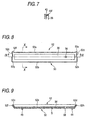
- Each side lip 40a-40d is formed into a tapered shape having a sectional shape thicker on the bottom surface 36 side and thinner gradually as the location goes toward the front end of the side lip 40a-40d, as shown in Figs. 5 and 6.- Incidentally, the shape of the side lip 40a-40d is not limited to the linear shape, but it may be a curved shape describing a gentle arc or the like.
- each corner in which the direction changes at the angle of 90 degrees from the side lip 40a, 40b along the long side to the side lip 40c, 40d along the short side connects the side lips 40a-40d with each other through a corner lip 40e-40h formed out of an arc.
- the corner lip 40e-40h is formed to have the same height from the mounting surface S as the height of the side lip 40a-40d.
- the corner lip 40e-40h is formed to have the same thickness in its sectional shape as that of the front end of the side lip 40a-40d as shown in Fig. 7.
- the corner lip 40e-40h is formed to be easier to be elastically deformable than the side lip 40a-40h.
- Figs. 4 and 6 shows the state of the lower side than the center line where the cap 34 has been pressed onto the nozzle surface 2 and thereby deformed. Incidentally, if the corner lip 40e-40h is thinner than the side lip 40a-40d, it will be easier to be elastically deformed, and then the embodiment can be carried out.
- a groove 42 is formed all over the circumference outside the side lips 40a-40d and the corner lips 40e-40h.
- the front end is urged to be deformed due to the groove 42 as shown in Fig. 6.
- protrusions 44 and 46 for positioning the cap 34 when it is attached to the swinging base 30 are formed on the back surface of the cap 34.
- the belt 10 is driven by the rotations of the rollers 8 so that printing paper passes under the print head 1 at a fixed speed. Then, ink droplets are ej ected from the print head 1 so that printing is performed line by line.
- the print head 1 At the time of maintenance for recovering the nozzles of the print head 1 from clogging or keeping the nozzles of the print head 1 moist, the print head 1 is moved from the ink ejection position to the standby position as shown by the arrow in Fig. 1 so that a predetermined space is formed between the print head 1 and the belt 10. Then, driven by the belt 19, the mounting base 12 is guided along the guide bars 14 and 16 and inserted into the space between the print head 1 and the belt 10.
- each side lip 40a-40d is elastically deformed as if the front end thereof falls down to the inside of the groove 42 as shown in Fig. 6.
- each corner lip 40e-40h is elastically deformed as if the front end of the corner 40e-40h falls down to the inside of the groove 42 similarly.
- the arc-like circumferential length of the corner lip 40e-40h connecting the front ends of the side lips 40a-40d on the opposite sides of the corner lip 40e-40h is elongated because the front ends of the side lips 40a-40d fall down to expand outward. Since the corner lip 40e-40h is formed to be easy to be elastically deformed, the corner lip 40e-40h expands in its circumferential direction.
- the front ends of the side lips 40a-40d fall down outward, and the front ends of the corner lips 40e-40h fall down outward while expanding in their circumferential directions respectively.
- the front ends of the side lips 40a-40d and the corner lips 40e-40h are brought into tight contact with the nozzle surface 2 so as to cover the nozzle surface 2 air-tightly with the bottom surface 36, the side lips 40a-40d and the corner lips 40e-40h.
- ink is ejected from the print head 1 for the sake of recovery of the nozzles or the like.
- the nozzles are covered air-tightlywith the bottom surface 36, the side lips 40a-40d and the corner lips 40e-40h, there is no fear that the ink leaks out.
- the cap 34 is pressed onto the nozzle surface 2 so as to keep the nozzle surface 2 moist.
- corner lips 40e-40h are formed to be easy to be elastically deformed in such a manner, it is possible to retain air-tightness.
- the corner lips 40e-40h are elastically deformed to retain the air-tightness, the tolerance for dimensional accuracy is so large that the number of caps 34 defective in dimensions can be reduced. Thus, the yield in manufacturing can be improved.
- a bottom surface 36 is formed to be opposed to the nozzle surface 2.
- the cap 50 is provided with a lip 52 surrounding the bottom surface 36 like a ring.
- the lip 52 protrudes toward the nozzle surface 2 of the print head 1.
- the lip 52 has a pair of side lips 52a and 52b provided linearly along the long sides of the bottom surface 36, and a pair of side lips 52c and 52d provided linearly along the short sides of the bottom surface 36.
- the shape of the side lip 52a-52d is not limited to the linear shape, but may be a curved shape.
- Each side lip 52a-52d is formed to have a sectional shape protruding obliquely from the bottom surface 36 side toward the nozzle surface 2, and to have a front end opened to the outside so as to overhang the bottom surface 36, as shown in Figs. 9 and 10.
- the side lip 52a-52d is formed to have a substantially uniform thickness between the bottom surface 36 side and the front end side or a thickness reduced slightly as the location goes toward the front end.
- each corner in which the direction changes at the angle of 90 degrees from the side lip 52a, 52b along the long side to the side lip 52c, 52d along the short side connects the side lips 52a-52d with each other through each corner lip 52e-52h.
- the corner lip 52e-52h is formed into an arc-like shape swelling outside the corner where the extensions of the side lips 52a-52d cross each other, as shown in Fig. 8.
- the corner lip 52e-52h is formed to protrude obliquely further outside the side lip 52a-52d between the bottom surface 36 and its front end.
- the corner lip 52e-52h is formed to be lower in height (height from the mounting surface S) than the side lip 52a-52d.
- the corner lip 52e-52h is formed to be the lowest at the intermediate point of its arc and to be inclined toward the front end of the side lip 52a-52d on either side so as to be equal in height to the side lip 52a-52d.
- the height of the corner lip 52e-52h may be determined by experiment or the like so that the height of the corner lip 52e-52h becomes equal to that of the side lip 52a-52d due to the deformation of the cap 50 when the cap 50 is pressed onto the nozzle surface 2.
- Figs. 8 and 10 show the state of the lower side than the center line where the cap 50 has been pressed onto the nozzle surface 2 and deformed.
- each side lip 52a-52d When the cap 50 is pressed onto the nozzle surface 2, each side lip 52a-52d is elastically deformed as if it falls down outward as shown in Figs. 8, 10 and 11B. Thus, the height of the side lip 50a-50d is lowered.
- each corner lip 52e-52h falls down outward similarly together with the side lip 52a-52d on either side on the side lip 52a-52d side. The corner lip 52e-52h does not fall down very much in its intermediate portion. Thus, the height of the corner lip 52e-52h is not lowered.
- the height of the side lip 52a-52d and the height of the corner lip 52e-52h become substantially equal to each other so as to be brought into tight contact with the nozzle surface 2 with no space therebetween.
- the nozzle surface 2 is covered air-tightly with the bottom surface 36, the side lips 52a-52d and the corner lips 52e-52h.
- the cap 50 is formed so that the side lips 52a-52d are deformed to be equal in height to the corner lips 52e-52h.
- the tolerance for dimensional accuracy is so large that the number of caps 50 defective in dimensions can be reduced.
- the yield in manufacturing can be improved.
- the invention is not limited to the embodiments described above, but it can be carried out in various modes without departing from the gist of the invention.
- the print head cap 34 and 52 is formed so that the corner lips 40e-40h and 52e-52h are easy to be elastically deformed.
- the tolerance for dimensional accuracy is so large that the number of defective caps in dimensions can be reduced.
- the yield in manufacturing can be improved.
- the elastic deformation is urged so that the air-tightness can be retained more surely.
- the side lips 52a-52d are deformed to have the same height as the corner lips 52e-52h, so that the air-tightness can be retained.
- the tolerance for dimensional accuracy is so large that the number of defective caps in dimensions can be reduced.
Abstract
Description
- The present invention relates to a print head cap for covering a nozzle surface therewith at the time of recovering a print head for ejecting ink droplets onto printing paper or at the time of keeping the print head moist.
- In the related art, as disclosed in JP-A-5-193150, there has been known a cap having a box-like sealing portion, a thick portion formed in the outer circumference of the sealing portion and a thin portion coupling the sealing portion with the thick portion. In order to improve the sealing performance of the cap pressed onto the nozzle surface of a print head, the cap is adapted so that the thin portion is deformed when the sealing portion is pressed onto the nozzle surface, so that the sealing portion is equalized and brought into tight contact with the nozzle surface.
- In addition, as disclosed in JP-A-10-211711, the cap is formed into a rectangular box-like shape corresponding to the shape of the nozzle surface.
- In such a related-art rectangular cap, particularly in such a cap for use in a full-line type print head in which a plurality nozzles are arrayed all over the width-direction area of printing paper, precision in flatness, dimensions and the like has to be high enough when the size of the print head in the direction in which the nozzles are arrayed is large and the cap is brought into tight contact with the nozzle surface uniformly. However, since the cap is formed out of an elastic body of rubber or the like, it is difficult to manufacture the cap particularly into such a high-precision shape. Thus, it is difficult to retain air-tightness required in the cap. In addition, since defective caps are often manufactured, there is also a problem that the yield in manufacturing deteriorates.
- A print head cap is disclosed herein, in which air-tightness can be retained while the yield in manufacturing can be improved.
- According to one aspect of the invention, a print head cap includes: a bottom surface; and a ring-like lip surrounding the bottom surface like a ring and protruding toward a nozzle surface of a print head of an ink jet printer and being elastically deformable, the ring-like lip to be pressed onto the nozzle surface to cover the nozzle surface therewith. The ring-like lip has corners that change a direction of surrounding the bottom surface. The corners are more elastically deformable than the other portion of the ring-like lip.
- Preferably, the corners are made thinner than the other portion.
- Preferably, the other portion includes a plurality of side lips. At least one of the corners includes a corner lip. The corner lip connects the side lips with each other.
- Preferably, each of the side lips has a front end and is formed into a tapered sectional shape which is smaller in width as a location goes from the bottom surface toward the front end; and the corner lip has substantially the same height as the side lips and is smaller than the side lips in thickness.
- Preferably, the ring-like lip is formed into a rectangular shape; and the side lips include a pair of linear side lips on long sides and a pair of linear side lips on short sides.
- Preferably, the ring-like lip includes a distal end and a groove that urges the distal end to be deformed in an outer side of the ring-like lip.
- According to another aspect of the invention, a print head cap includes: a bottom surface; and an elastically deformable lip surrounding the bottom surface like a ring and protruding toward a nozzle surface of a print head of an ink jet printer, the lip to be pressed onto the nozzle surface to cover the nozzle surface therewith. The lip has a plurality of side lips and a plurality of corner lips connecting the side lips with each other and changing a direction of surrounding the bottom surface. At least one of the plurality of corner lips is formed into an arc-like shape swelling outward and is formed to be lower in height than the side lips.
- Preferably, the lip protrudes obliquely outward from the bottom surface.
- The present invention may be more readily described with reference to the accompanying drawings:
- Fig. 1 is a configuration diagram of a printer using a print head cap according to a first embodiment of the invention.
- Fig. 2 is a plan view of a capping mechanism using the print head cap according to the embodiment.
- Fig. 3 is a sectional view taken on line 3-3 in Fig. 2.
- Fig. 4 is a plan view of the print head cap according to the embodiment.
- Fig. 5 is a sectional view taken on line 5-5 in Fig. 4.
- Fig. 6 is a sectional view taken on line 6-6 in Fig. 4.
- Fig. 7 is a sectional view taken on line 7-7 in Fig. 4.
- Fig. 8 is a plan view of a print head cap according to a second embodiment of the invention.
- Fig. 9 is a sectional view taken on line 9-9 in Fig. 8.
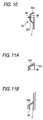
- Fig. 10 is a sectional view taken on line 10-10 in Fig. 8.
- Figs. 11A and 11B are explanatory views showing the falling of a lip of the print head cap according to the second embodiment.
-
- Embodiments of the invention will be described below in detail with reference to the drawings.
- As shown in Fig. 1, a printer according to this embodiment has a full-line type print head 1, and a large number of not-shown nozzles are formed,in the print head 1 in a direction perpendicular to the direction of feeding printing paper. A
nozzle surface 2 in which the nozzles are opened is disposed to be opposed to the printing paper. - In addition, the print head 1 is of an ink jet system for ej ecting ink droplets onto the printing paper. For example, such a print head 1 is provided for respective colors of yellow, magenta, cyan and black. Incidentally, each part of the print head 1 is supplied with its corresponding color ink from an ink cartridge 4 through an ink supply mechanism 6.
- The printing paper is fed in tight contact with the surface of a
belt 10 laid between a pair of rollers 8 (only one of which is shown). Each print head 1 is disposed in a body case 11 movably in a direction perpendicular to the surface of thebelt 10 on which the paper is mounted. At the time of carrying out printing, the print head 1 is moved to an ink ejection position close to the printing paper as shown in Fig. 2. At the time of maintenance, the print head 1 is moved to a standby position in which a predetermined space is formed between the print head 1 and the printing paper and which is more distant from thebelt 10 than the ink ejection position, as shown in Fig. 1. - A
mounting base 12 which can be inserted into this space is provided. As shown in Fig. 3, themounting base 12 is supported on a pair ofguide bars members 18 so that themounting base 12 can move forward/backward linearly. Theguide bars belt 19 is laid in parallel with theguide bars mounting base 12 and thebelt 19 are fastened to each other through alock member 20. - When the
belt 19 is driven by a motor, themounting base 12 slides along theguide bars mounting base 12 canmove forward/backwardbetween a maintenance position (position designated by the solid line in Fig. 1) in which themounting base 12 is inserted into the space between the print head 1 and the printing paper and a retractionposition (position designated by the chain double-dashed line in Fig. 1) in which themounting base 12 is retracted from the space to the upper side of the ink cartridge 4 at the time of printing. - A
capping mechanism 22 is mounted on themounting base 12. Thecapping mechanism 22 has a plurality oflinks 24 one ends of which are supported swingably on themounting base 12, and acap base 26 on which the other ends of the plurality oflinks 24 are supported swingably. Thecap base 26 is configured as follows. That is, when themounting base 12 is moved to the maintenance position, eachengagement portion 28 integrated with thecap base 26 abuts against a fixed side provided in the print head 1 so as to keep thecap base 26 parallel with thenozzle surface 2 while being moved toward thenozzle surface 2 so as to describe an arc. -
Aswinging base 30 is supported on thecap base 26 swingably around apin 32 as shown in Fig. 3. On each of opposite sides of thepin 32, acoil spring cap base 26 and theswinging base 30. Four print head caps 34 (hereinafter referred to as "caps 34") are attached to theswinging base 30 correspondingly to the respective colors of the print head 1 in this embodiment. Thecaps 34 are formed out of an elastically deformable material, particularly a material resistant to ink, such as butyl rubber or EPDM. - A
bottom surface 36 opposed to thenozzle surface 2 is formed in thecap 34 as shown in Fig. 3. Thebottom surface 36 is substantially flat, and anexhaust hole 38 opened in thebottom surface 36 is formed in thecap 34. Theexhaust hole 38 is designed to be connected to a not-shown exhaust duct so as to be able to exhaust ink. - In each
cap 34, alip 40 is provided to surround thebottom surface 36 like a ring. Thelip 40 protrudes toward thenozzle surface 2 of the print head 1. In this embodiment, thelip 40 has a pair ofside lips bottom surface 36, and a pair ofside lips bottom surface 36. - Each
side lip 40a-40d is formed into a tapered shape having a sectional shape thicker on thebottom surface 36 side and thinner gradually as the location goes toward the front end of theside lip 40a-40d, as shown in Figs. 5 and 6.- Incidentally, the shape of theside lip 40a-40d is not limited to the linear shape, but it may be a curved shape describing a gentle arc or the like. - Of the corners of the
lip 40 in which the direction of surrounding thebottom surface 36 changes, in this embodiment, each corner in which the direction changes at the angle of 90 degrees from theside lip side lip side lips 40a-40d with each other through acorner lip 40e-40h formed out of an arc. Thecorner lip 40e-40h is formed to have the same height from the mounting surface S as the height of theside lip 40a-40d. In this embodiment, thecorner lip 40e-40h is formed to have the same thickness in its sectional shape as that of the front end of theside lip 40a-40d as shown in Fig. 7. Thecorner lip 40e-40h is formed to be easier to be elastically deformable than theside lip 40a-40h. Figs. 4 and 6 shows the state of the lower side than the center line where thecap 34 has been pressed onto thenozzle surface 2 and thereby deformed. Incidentally, if thecorner lip 40e-40h is thinner than theside lip 40a-40d, it will be easier to be elastically deformed, and then the embodiment can be carried out. - A
groove 42 is formed all over the circumference outside theside lips 40a-40d and thecorner lips 40e-40h. When each front end of theside lips 40a-40d and thecorner lips 40e-40h is pressed onto thenozzle surface 2, the front end is urged to be deformed due to thegroove 42 as shown in Fig. 6. Incidentally,protrusions cap 34 when it is attached to the swingingbase 30 are formed on the back surface of thecap 34. - Next, description will be made on the operation of the print head cap according to this embodiment.
- At the time of printing, the
belt 10 is driven by the rotations of therollers 8 so that printing paper passes under the print head 1 at a fixed speed. Then, ink droplets are ej ected from the print head 1 so that printing is performed line by line. - At the time of maintenance for recovering the nozzles of the print head 1 from clogging or keeping the nozzles of the print head 1 moist, the print head 1 is moved from the ink ejection position to the standby position as shown by the arrow in Fig. 1 so that a predetermined space is formed between the print head 1 and the
belt 10. Then, driven by thebelt 19, the mountingbase 12 is guided along the guide bars 14 and 16 and inserted into the space between the print head 1 and thebelt 10. - When each
engagement portion 28 abuts against the fixed side of the printer, and the mountingbase 12 is moved further, thecap base 26 is moved to describe an arc from the separation position shown in Fig. 3 toward thenozzle surface 2 by the plurality oflinks 24 while retaining its parallelism with thenozzle surface 2. Then, thecap 34 is pressed onto thenozzle surface 2. In that event, the swingingbase 30 swings around thepin 32 so as to press thecap 34 onto thenozzle surface 2 by uniform pressing force. - When the
cap 34 is pressed onto thenozzle surface 2, eachside lip 40a-40d is elastically deformed as if the front end thereof falls down to the inside of thegroove 42 as shown in Fig. 6. Then, eachcorner lip 40e-40h is elastically deformed as if the front end of thecorner 40e-40h falls down to the inside of thegroove 42 similarly. At the same time, the arc-like circumferential length of thecorner lip 40e-40h connecting the front ends of theside lips 40a-40d on the opposite sides of thecorner lip 40e-40h is elongated because the front ends of theside lips 40a-40d fall down to expand outward. Since thecorner lip 40e-40h is formed to be easy to be elastically deformed, thecorner lip 40e-40h expands in its circumferential direction. - Accordingly, when the
cap 34 is pressed onto thenozzle surface 2, as shown in Figs. 4 and 6, the front ends of theside lips 40a-40d fall down outward, and the front ends of thecorner lips 40e-40h fall down outward while expanding in their circumferential directions respectively. Thus, the front ends of theside lips 40a-40d and thecorner lips 40e-40h are brought into tight contact with thenozzle surface 2 so as to cover thenozzle surface 2 air-tightly with thebottom surface 36, theside lips 40a-40d and thecorner lips 40e-40h. - After that, ink is ejected from the print head 1 for the sake of recovery of the nozzles or the like. In that event, since the nozzles are covered air-tightlywith the
bottom surface 36, theside lips 40a-40d and thecorner lips 40e-40h, there is no fear that the ink leaks out. Incidentally, not only at the time of recovery but also at any time when printing is not carried out, thecap 34 is pressed onto thenozzle surface 2 so as to keep thenozzle surface 2 moist. - Since the
corner lips 40e-40h are formed to be easy to be elastically deformed in such a manner, it is possible to retain air-tightness. In addition, since thecorner lips 40e-40h are elastically deformed to retain the air-tightness, the tolerance for dimensional accuracy is so large that the number ofcaps 34 defective in dimensions can be reduced. Thus, the yield in manufacturing can be improved. - Next, description will be made on a print head cap according to a second embodiment different from the aforementioned embodiment, with reference to Figs. 8 to 10, 11A and 11B . Members the same as those in the aforementioned embodiment are denoted by the same reference numerals correspondingly, and their detailed description will be omitted.
- As shown in Fig. 8, in a
cap 50, abottom surface 36 is formed to be opposed to thenozzle surface 2. Thecap 50 is provided with alip 52 surrounding thebottom surface 36 like a ring. Thelip 52 protrudes toward thenozzle surface 2 of the print head 1. In this embodiment, thelip 52 has a pair ofside lips bottom surface 36, and a pair ofside lips bottom surface 36. Also in this case, the shape of theside lip 52a-52d is not limited to the linear shape, but may be a curved shape. - Each
side lip 52a-52d is formed to have a sectional shape protruding obliquely from thebottom surface 36 side toward thenozzle surface 2, and to have a front end opened to the outside so as to overhang thebottom surface 36, as shown in Figs. 9 and 10. Theside lip 52a-52d is formed to have a substantially uniform thickness between thebottom surface 36 side and the front end side or a thickness reduced slightly as the location goes toward the front end. - Of the corners of the
lip 52 in which the direction of surrounding thebottom surface 36 changes, in this embodiment, each corner in which the direction changes at the angle of 90 degrees from theside lip side lip side lips 52a-52d with each other through eachcorner lip 52e-52h. Thecorner lip 52e-52h is formed into an arc-like shape swelling outside the corner where the extensions of theside lips 52a-52d cross each other, as shown in Fig. 8. As shown in Fig. 9 and 11A, thecorner lip 52e-52h is formed to protrude obliquely further outside theside lip 52a-52d between thebottom surface 36 and its front end. - In addition, the
corner lip 52e-52h is formed to be lower in height (height from the mounting surface S) than theside lip 52a-52d. Thecorner lip 52e-52h is formed to be the lowest at the intermediate point of its arc and to be inclined toward the front end of theside lip 52a-52d on either side so as to be equal in height to theside lip 52a-52d. The height of thecorner lip 52e-52h may be determined by experiment or the like so that the height of thecorner lip 52e-52h becomes equal to that of theside lip 52a-52d due to the deformation of thecap 50 when thecap 50 is pressed onto thenozzle surface 2. Incidentally, Figs. 8 and 10 show the state of the lower side than the center line where thecap 50 has been pressed onto thenozzle surface 2 and deformed. - Next, description will be made on the operation of the print head cap according to this second embodiment.
- When the
cap 50 is pressed onto thenozzle surface 2, eachside lip 52a-52d is elastically deformed as if it falls down outward as shown in Figs. 8, 10 and 11B. Thus, the height of the side lip 50a-50d is lowered. On the other hand, eachcorner lip 52e-52h falls down outward similarly together with theside lip 52a-52d on either side on theside lip 52a-52d side. Thecorner lip 52e-52h does not fall down very much in its intermediate portion. Thus, the height of thecorner lip 52e-52h is not lowered. - Accordingly, when the
cap 50 is pressed onto thenozzle surface 2, the height of theside lip 52a-52d and the height of thecorner lip 52e-52h become substantially equal to each other so as to be brought into tight contact with thenozzle surface 2 with no space therebetween. Thus, thenozzle surface 2 is covered air-tightly with thebottom surface 36, theside lips 52a-52d and thecorner lips 52e-52h. - In such a manner, the
cap 50 is formed so that theside lips 52a-52d are deformed to be equal in height to thecorner lips 52e-52h. Thus, it is possible to retain air-tightness. In addition, since the air-tightness is retained due to deformation of theside lips 52a-52d, the tolerance for dimensional accuracy is so large that the number ofcaps 50 defective in dimensions can be reduced. Thus, the yield in manufacturing can be improved. - The invention is not limited to the embodiments described above, but it can be carried out in various modes without departing from the gist of the invention.
- As has been described in detail above, the
print head cap corner lips 40e-40h and 52e-52h are easy to be elastically deformed. Thus, it is possible to retain air-tightness. In addition, since the air-tightness is retained due to the elastic deformation of thecorner lips 40e-40h and 52e-52h, the tolerance for dimensional accuracy is so large that the number of defective caps in dimensions can be reduced. Thus, there is an advantage that the yield in manufacturing can be improved. Particularly, when agroove 42 is formed outside thelip 40, the elastic deformation is urged so that the air-tightness can be retained more surely. - In addition, in the
print head cap 52, theside lips 52a-52d are deformed to have the same height as thecorner lips 52e-52h, so that the air-tightness can be retained. In addition, since the air-tightness is retained due to the deformation of theside lips 52a-52d, the tolerance for dimensional accuracy is so large that the number of defective caps in dimensions can be reduced. Thus, there is an advantage that the yield in manufacturing can be improved. - While the invention has been described in conjunction with the specific embodiments described above, many equivalent alternatives, modifications and variations may become apparent to those skilled in the art when given this disclosure. Accordingly, the exemplary embodiments of the invention as set forth above are considered to be illustrative and not limiting. Various changes to the described embodiments may be made without departing from the spirit and scope of the invention.
Claims (8)
- A print head cap comprising:wherein the ring-like lip has corners that change a direction of surrounding the bottom surface; anda bottom surface; anda ring-like lip surrounding the bottom surface like a ring, protruding toward a nozzle surface of a print head of an ink jet printer and being elastically deformable, the ring-like lip to be pressed onto the nozzle surface to cover the nozzle surface therewith;
the corners are more elastically deformable than the other portion of the ring-like lip. - The print head cap according to claim 1,
wherein the corners are made thinner than the other portion. - The print head cap according to claim 1 or 2,
wherein the other portion includes a plurality of side lips;
at least one of the corners includes a corner lip; and
the corner lip connects the side lips with each other. - The print head cap according to claim 3,
wherein each of the side lips has a front end and is formed into a tapered sectional shape which is smaller in width as a location goes from the bottom surface toward the front end; and
the corner lip has substantially the same height as the side lips and is smaller than the side lips in thickness. - The print head lip according to claim 3 or 4,
wherein the ring-like lip is formed into a rectangular shape; and
the side lips include a pair of linear side lips on long sides and a pair of linear side lips on short sides. - The print head cap according to any preceding claim,
wherein the ring-like lip includes a distal end and a groove that urges the distal end to be deformed in an outer side of the ring-like lip. - A print head cap comprising:wherein the lip has a plurality of side lips and aplurality of corner lips connecting the side lips with each other and changing a direction of surrounding the bottom surface; and at least one of the plurality of corner lips is formed into an arc-like shape swelling outward and is formed to be lower in height than the side lips.a bottom surface; andan elastically deformable lip surrounding the bottom surface like a ring and protruding toward a nozzle surface of a print head of an ink jet printer, the lip to be pressed onto the nozzle surface to cover the nozzle surface therewith;
- The print head cap according to claim 7, wherein the lip protrudes obliquely outward from the bottom surface.
Applications Claiming Priority (2)
| Application Number | Priority Date | Filing Date | Title |
|---|---|---|---|
| JP2003088717 | 2003-03-27 | ||
| JP2003088717A JP3991900B2 (en) | 2003-03-27 | 2003-03-27 | Print head cap |
Publications (3)
| Publication Number | Publication Date |
|---|---|
| EP1462258A2 true EP1462258A2 (en) | 2004-09-29 |
| EP1462258A3 EP1462258A3 (en) | 2005-09-21 |
| EP1462258B1 EP1462258B1 (en) | 2009-12-16 |
Family
ID=32821557
Family Applications (1)
| Application Number | Title | Priority Date | Filing Date |
|---|---|---|---|
| EP04251757A Expired - Lifetime EP1462258B1 (en) | 2003-03-27 | 2004-03-26 | Print head cap |
Country Status (6)
| Country | Link |
|---|---|
| US (2) | US7419240B2 (en) |
| EP (1) | EP1462258B1 (en) |
| JP (1) | JP3991900B2 (en) |
| CN (3) | CN2715994Y (en) |
| AT (1) | ATE452029T1 (en) |
| DE (1) | DE602004024612D1 (en) |
Families Citing this family (9)
| Publication number | Priority date | Publication date | Assignee | Title |
|---|---|---|---|---|
| JP3991900B2 (en) * | 2003-03-27 | 2007-10-17 | ブラザー工業株式会社 | Print head cap |
| TWI247685B (en) * | 2004-07-07 | 2006-01-21 | Benq Corp | Capping device for capping a print head |
| JP4241792B2 (en) * | 2006-09-25 | 2009-03-18 | ブラザー工業株式会社 | Cap and inkjet protection assembly |
| JP5012765B2 (en) * | 2008-11-07 | 2012-08-29 | ブラザー工業株式会社 | Head cap |
| WO2011136788A1 (en) * | 2010-04-30 | 2011-11-03 | Hewlett-Packard Development Company, L.P. | Capping for inkjet printers |
| US8434853B1 (en) * | 2011-10-25 | 2013-05-07 | Hewlett-Packard Development Company, L.P. | Printhead cap assembly |
| JP5873560B2 (en) * | 2011-10-31 | 2016-03-01 | ヒューレット−パッカード デベロップメント カンパニー エル.ピー.Hewlett‐Packard Development Company, L.P. | Capping device for print head |
| CN103600585B (en) * | 2013-08-31 | 2016-04-06 | 深圳市全印图文技术有限公司 | For method for moisturizing and the moisturizing bar of digital decorating machine shower nozzle |
| CN106827817A (en) * | 2015-12-23 | 2017-06-13 | 石立公 | For the stopper with inner bulge of random labelling head |
Citations (4)
| Publication number | Priority date | Publication date | Assignee | Title |
|---|---|---|---|---|
| US5448270A (en) * | 1992-08-26 | 1995-09-05 | Hewlett-Packard Company | Ink-jet printhead cap having suspended lip |
| EP0744294A1 (en) * | 1995-05-25 | 1996-11-27 | Seiko Epson Corporation | Capping device for ink jet recording head |
| EP1074388A1 (en) * | 1997-03-25 | 2001-02-07 | Seiko Epson Corporation | Ink jet recording apparatus and cap unit for the recording head |
| US6517185B1 (en) * | 2001-03-09 | 2003-02-11 | Lexmark International, Inc. | Low force ink jet printhead capping system |
Family Cites Families (7)
| Publication number | Priority date | Publication date | Assignee | Title |
|---|---|---|---|---|
| JP3100451B2 (en) | 1992-01-16 | 2000-10-16 | キヤノン株式会社 | Ink jet recording device |
| JP2878214B2 (en) * | 1996-11-20 | 1999-04-05 | 新潟日本電気株式会社 | Ink jet recording device |
| JPH10211711A (en) | 1996-11-29 | 1998-08-11 | Seiko Epson Corp | Capping device and ink jet recording apparatus using the same |
| JP4630452B2 (en) | 2000-09-29 | 2011-02-09 | セイコーインスツル株式会社 | Cap member manufacturing method |
| JP2002326366A (en) * | 2001-04-27 | 2002-11-12 | Canon Inc | Inkjet recorder and cap for recording head |
| JP4192550B2 (en) | 2002-10-16 | 2008-12-10 | セイコーエプソン株式会社 | Liquid ejector |
| JP3991900B2 (en) * | 2003-03-27 | 2007-10-17 | ブラザー工業株式会社 | Print head cap |
-
2003
- 2003-03-27 JP JP2003088717A patent/JP3991900B2/en not_active Expired - Fee Related
-
2004
- 2004-03-26 EP EP04251757A patent/EP1462258B1/en not_active Expired - Lifetime
- 2004-03-26 CN CNU2004200064467U patent/CN2715994Y/en not_active Expired - Lifetime
- 2004-03-26 CN CNB2004100313816A patent/CN100455443C/en not_active Expired - Fee Related
- 2004-03-26 AT AT04251757T patent/ATE452029T1/en not_active IP Right Cessation
- 2004-03-26 DE DE602004024612T patent/DE602004024612D1/en not_active Expired - Lifetime
- 2004-03-26 CN CN2008100022274A patent/CN101254697B/en not_active Expired - Fee Related
- 2004-03-26 US US10/809,341 patent/US7419240B2/en active Active
-
2006
- 2006-08-30 US US11/512,374 patent/US7585048B2/en active Active
Patent Citations (4)
| Publication number | Priority date | Publication date | Assignee | Title |
|---|---|---|---|---|
| US5448270A (en) * | 1992-08-26 | 1995-09-05 | Hewlett-Packard Company | Ink-jet printhead cap having suspended lip |
| EP0744294A1 (en) * | 1995-05-25 | 1996-11-27 | Seiko Epson Corporation | Capping device for ink jet recording head |
| EP1074388A1 (en) * | 1997-03-25 | 2001-02-07 | Seiko Epson Corporation | Ink jet recording apparatus and cap unit for the recording head |
| US6517185B1 (en) * | 2001-03-09 | 2003-02-11 | Lexmark International, Inc. | Low force ink jet printhead capping system |
Also Published As
| Publication number | Publication date |
|---|---|
| US7585048B2 (en) | 2009-09-08 |
| EP1462258B1 (en) | 2009-12-16 |
| EP1462258A3 (en) | 2005-09-21 |
| US20040189738A1 (en) | 2004-09-30 |
| ATE452029T1 (en) | 2010-01-15 |
| CN2715994Y (en) | 2005-08-10 |
| CN100455443C (en) | 2009-01-28 |
| US7419240B2 (en) | 2008-09-02 |
| US20060284923A1 (en) | 2006-12-21 |
| CN101254697A (en) | 2008-09-03 |
| JP2004291480A (en) | 2004-10-21 |
| DE602004024612D1 (en) | 2010-01-28 |
| JP3991900B2 (en) | 2007-10-17 |
| CN101254697B (en) | 2011-11-23 |
| CN1533895A (en) | 2004-10-06 |
Similar Documents
| Publication | Publication Date | Title |
|---|---|---|
| US7585048B2 (en) | Print head cap | |
| CN100475539C (en) | Ink-jet image forming apparatus having cap member | |
| US9764553B2 (en) | Liquid ejecting apparatus | |
| US9278540B2 (en) | Liquid storage container and liquid ejection apparatus | |
| US7427122B2 (en) | Printer maintenance apparatus | |
| JP2003528754A (en) | Printhead module overlap array configuration | |
| EP1332880B1 (en) | Snout-encompassing capping system for inkjet printheads | |
| US6883897B2 (en) | Ink jet recording apparatus and cleaning unit thereof | |
| US6383335B1 (en) | Heat bonding apparatus for manufacturing an ink-jet printhead | |
| US8960859B2 (en) | Ink jet printing apparatus | |
| JP3704820B2 (en) | Ink-jet head cap means | |
| US11504968B2 (en) | Liquid ejection head and liquid ejection apparatus | |
| US7686420B2 (en) | Ink jet recording apparatus | |
| JP3474976B2 (en) | Cap device for inkjet printer | |
| US20220203691A1 (en) | Liquid ejection apparatus | |
| JPH09314853A (en) | Ink jet recording apparatus | |
| JPH08267788A (en) | Ink jet printer |
Legal Events
| Date | Code | Title | Description |
|---|---|---|---|
| PUAI | Public reference made under article 153(3) epc to a published international application that has entered the european phase |
Free format text: ORIGINAL CODE: 0009012 |
|
| AK | Designated contracting states |
Kind code of ref document: A2 Designated state(s): AT BE BG CH CY CZ DE DK EE ES FI FR GB GR HU IE IT LI LU MC NL PL PT RO SE SI SK TR |
|
| AX | Request for extension of the european patent |
Extension state: AL LT LV MK |
|
| PUAL | Search report despatched |
Free format text: ORIGINAL CODE: 0009013 |
|
| AK | Designated contracting states |
Kind code of ref document: A3 Designated state(s): AT BE BG CH CY CZ DE DK EE ES FI FR GB GR HU IE IT LI LU MC NL PL PT RO SE SI SK TR |
|
| AX | Request for extension of the european patent |
Extension state: AL LT LV MK |
|
| 17P | Request for examination filed |
Effective date: 20051117 |
|
| AKX | Designation fees paid |
Designated state(s): AT BE BG CH CY CZ DE DK EE ES FI FR GB GR HU IE IT LI LU MC NL PL PT RO SE SI SK TR |
|
| 17Q | First examination report despatched |
Effective date: 20080222 |
|
| GRAP | Despatch of communication of intention to grant a patent |
Free format text: ORIGINAL CODE: EPIDOSNIGR1 |
|
| GRAS | Grant fee paid |
Free format text: ORIGINAL CODE: EPIDOSNIGR3 |
|
| GRAA | (expected) grant |
Free format text: ORIGINAL CODE: 0009210 |
|
| AK | Designated contracting states |
Kind code of ref document: B1 Designated state(s): AT BE BG CH CY CZ DE DK EE ES FI FR GB GR HU IE IT LI LU MC NL PL PT RO SE SI SK TR |
|
| REG | Reference to a national code |
Ref country code: GB Ref legal event code: FG4D |
|
| REG | Reference to a national code |
Ref country code: CH Ref legal event code: EP |
|
| REG | Reference to a national code |
Ref country code: IE Ref legal event code: FG4D |
|
| REF | Corresponds to: |
Ref document number: 602004024612 Country of ref document: DE Date of ref document: 20100128 Kind code of ref document: P |
|
| REG | Reference to a national code |
Ref country code: NL Ref legal event code: VDEP Effective date: 20091216 |
|
| PG25 | Lapsed in a contracting state [announced via postgrant information from national office to epo] |
Ref country code: SE Free format text: LAPSE BECAUSE OF FAILURE TO SUBMIT A TRANSLATION OF THE DESCRIPTION OR TO PAY THE FEE WITHIN THE PRESCRIBED TIME-LIMIT Effective date: 20091216 Ref country code: FI Free format text: LAPSE BECAUSE OF FAILURE TO SUBMIT A TRANSLATION OF THE DESCRIPTION OR TO PAY THE FEE WITHIN THE PRESCRIBED TIME-LIMIT Effective date: 20091216 |
|
| PG25 | Lapsed in a contracting state [announced via postgrant information from national office to epo] |
Ref country code: PL Free format text: LAPSE BECAUSE OF FAILURE TO SUBMIT A TRANSLATION OF THE DESCRIPTION OR TO PAY THE FEE WITHIN THE PRESCRIBED TIME-LIMIT Effective date: 20091216 Ref country code: SI Free format text: LAPSE BECAUSE OF FAILURE TO SUBMIT A TRANSLATION OF THE DESCRIPTION OR TO PAY THE FEE WITHIN THE PRESCRIBED TIME-LIMIT Effective date: 20091216 |
|
| PG25 | Lapsed in a contracting state [announced via postgrant information from national office to epo] |
Ref country code: AT Free format text: LAPSE BECAUSE OF FAILURE TO SUBMIT A TRANSLATION OF THE DESCRIPTION OR TO PAY THE FEE WITHIN THE PRESCRIBED TIME-LIMIT Effective date: 20091216 |
|
| PG25 | Lapsed in a contracting state [announced via postgrant information from national office to epo] |
Ref country code: PT Free format text: LAPSE BECAUSE OF FAILURE TO SUBMIT A TRANSLATION OF THE DESCRIPTION OR TO PAY THE FEE WITHIN THE PRESCRIBED TIME-LIMIT Effective date: 20100416 Ref country code: BG Free format text: LAPSE BECAUSE OF FAILURE TO SUBMIT A TRANSLATION OF THE DESCRIPTION OR TO PAY THE FEE WITHIN THE PRESCRIBED TIME-LIMIT Effective date: 20100316 Ref country code: RO Free format text: LAPSE BECAUSE OF FAILURE TO SUBMIT A TRANSLATION OF THE DESCRIPTION OR TO PAY THE FEE WITHIN THE PRESCRIBED TIME-LIMIT Effective date: 20091216 Ref country code: NL Free format text: LAPSE BECAUSE OF FAILURE TO SUBMIT A TRANSLATION OF THE DESCRIPTION OR TO PAY THE FEE WITHIN THE PRESCRIBED TIME-LIMIT Effective date: 20091216 Ref country code: ES Free format text: LAPSE BECAUSE OF FAILURE TO SUBMIT A TRANSLATION OF THE DESCRIPTION OR TO PAY THE FEE WITHIN THE PRESCRIBED TIME-LIMIT Effective date: 20100327 Ref country code: EE Free format text: LAPSE BECAUSE OF FAILURE TO SUBMIT A TRANSLATION OF THE DESCRIPTION OR TO PAY THE FEE WITHIN THE PRESCRIBED TIME-LIMIT Effective date: 20091216 |
|
| PG25 | Lapsed in a contracting state [announced via postgrant information from national office to epo] |
Ref country code: CZ Free format text: LAPSE BECAUSE OF FAILURE TO SUBMIT A TRANSLATION OF THE DESCRIPTION OR TO PAY THE FEE WITHIN THE PRESCRIBED TIME-LIMIT Effective date: 20091216 Ref country code: SK Free format text: LAPSE BECAUSE OF FAILURE TO SUBMIT A TRANSLATION OF THE DESCRIPTION OR TO PAY THE FEE WITHIN THE PRESCRIBED TIME-LIMIT Effective date: 20091216 Ref country code: BE Free format text: LAPSE BECAUSE OF FAILURE TO SUBMIT A TRANSLATION OF THE DESCRIPTION OR TO PAY THE FEE WITHIN THE PRESCRIBED TIME-LIMIT Effective date: 20091216 |
|
| PLBE | No opposition filed within time limit |
Free format text: ORIGINAL CODE: 0009261 |
|
| STAA | Information on the status of an ep patent application or granted ep patent |
Free format text: STATUS: NO OPPOSITION FILED WITHIN TIME LIMIT |
|
| PG25 | Lapsed in a contracting state [announced via postgrant information from national office to epo] |
Ref country code: GR Free format text: LAPSE BECAUSE OF FAILURE TO SUBMIT A TRANSLATION OF THE DESCRIPTION OR TO PAY THE FEE WITHIN THE PRESCRIBED TIME-LIMIT Effective date: 20100317 Ref country code: CY Free format text: LAPSE BECAUSE OF FAILURE TO SUBMIT A TRANSLATION OF THE DESCRIPTION OR TO PAY THE FEE WITHIN THE PRESCRIBED TIME-LIMIT Effective date: 20091216 Ref country code: MC Free format text: LAPSE BECAUSE OF NON-PAYMENT OF DUE FEES Effective date: 20100331 |
|
| REG | Reference to a national code |
Ref country code: CH Ref legal event code: PL |
|
| 26N | No opposition filed |
Effective date: 20100917 |
|
| PG25 | Lapsed in a contracting state [announced via postgrant information from national office to epo] |
Ref country code: IE Free format text: LAPSE BECAUSE OF NON-PAYMENT OF DUE FEES Effective date: 20100326 Ref country code: DK Free format text: LAPSE BECAUSE OF FAILURE TO SUBMIT A TRANSLATION OF THE DESCRIPTION OR TO PAY THE FEE WITHIN THE PRESCRIBED TIME-LIMIT Effective date: 20091216 |
|
| PG25 | Lapsed in a contracting state [announced via postgrant information from national office to epo] |
Ref country code: LI Free format text: LAPSE BECAUSE OF NON-PAYMENT OF DUE FEES Effective date: 20100331 Ref country code: CH Free format text: LAPSE BECAUSE OF NON-PAYMENT OF DUE FEES Effective date: 20100331 |
|
| PG25 | Lapsed in a contracting state [announced via postgrant information from national office to epo] |
Ref country code: IT Free format text: LAPSE BECAUSE OF FAILURE TO SUBMIT A TRANSLATION OF THE DESCRIPTION OR TO PAY THE FEE WITHIN THE PRESCRIBED TIME-LIMIT Effective date: 20091216 |
|
| PG25 | Lapsed in a contracting state [announced via postgrant information from national office to epo] |
Ref country code: HU Free format text: LAPSE BECAUSE OF FAILURE TO SUBMIT A TRANSLATION OF THE DESCRIPTION OR TO PAY THE FEE WITHIN THE PRESCRIBED TIME-LIMIT Effective date: 20100617 Ref country code: LU Free format text: LAPSE BECAUSE OF NON-PAYMENT OF DUE FEES Effective date: 20100326 |
|
| PG25 | Lapsed in a contracting state [announced via postgrant information from national office to epo] |
Ref country code: TR Free format text: LAPSE BECAUSE OF FAILURE TO SUBMIT A TRANSLATION OF THE DESCRIPTION OR TO PAY THE FEE WITHIN THE PRESCRIBED TIME-LIMIT Effective date: 20091216 |
|
| REG | Reference to a national code |
Ref country code: FR Ref legal event code: PLFP Year of fee payment: 13 |
|
| REG | Reference to a national code |
Ref country code: FR Ref legal event code: PLFP Year of fee payment: 14 |
|
| REG | Reference to a national code |
Ref country code: FR Ref legal event code: PLFP Year of fee payment: 15 |
|
| PGFP | Annual fee paid to national office [announced via postgrant information from national office to epo] |
Ref country code: GB Payment date: 20200318 Year of fee payment: 17 |
|
| PGFP | Annual fee paid to national office [announced via postgrant information from national office to epo] |
Ref country code: FR Payment date: 20200214 Year of fee payment: 17 |
|
| GBPC | Gb: european patent ceased through non-payment of renewal fee |
Effective date: 20210326 |
|
| PG25 | Lapsed in a contracting state [announced via postgrant information from national office to epo] |
Ref country code: FR Free format text: LAPSE BECAUSE OF NON-PAYMENT OF DUE FEES Effective date: 20210331 Ref country code: GB Free format text: LAPSE BECAUSE OF NON-PAYMENT OF DUE FEES Effective date: 20210326 |
|
| PGFP | Annual fee paid to national office [announced via postgrant information from national office to epo] |
Ref country code: DE Payment date: 20230131 Year of fee payment: 20 |
|
| REG | Reference to a national code |
Ref country code: DE Ref legal event code: R071 Ref document number: 602004024612 Country of ref document: DE |