EP1462145A1 - Method and apparatus for skin absorption enhancement and transdermal drug delivery - Google Patents
Method and apparatus for skin absorption enhancement and transdermal drug delivery Download PDFInfo
- Publication number
- EP1462145A1 EP1462145A1 EP04290817A EP04290817A EP1462145A1 EP 1462145 A1 EP1462145 A1 EP 1462145A1 EP 04290817 A EP04290817 A EP 04290817A EP 04290817 A EP04290817 A EP 04290817A EP 1462145 A1 EP1462145 A1 EP 1462145A1
- Authority
- EP
- European Patent Office
- Prior art keywords
- skin
- probe
- patient
- substance
- electrodes
- Prior art date
- Legal status (The legal status is an assumption and is not a legal conclusion. Google has not performed a legal analysis and makes no representation as to the accuracy of the status listed.)
- Granted
Links
- 238000000034 method Methods 0.000 title claims abstract description 14
- 230000037384 skin absorption Effects 0.000 title description 19
- 231100000274 skin absorption Toxicity 0.000 title description 19
- 238000013271 transdermal drug delivery Methods 0.000 title description 2
- 239000000523 sample Substances 0.000 claims abstract description 112
- 239000000126 substance Substances 0.000 claims abstract description 77
- 238000010521 absorption reaction Methods 0.000 claims abstract description 26
- 238000011282 treatment Methods 0.000 claims abstract description 21
- 230000002708 enhancing effect Effects 0.000 claims abstract description 5
- 210000003491 skin Anatomy 0.000 description 195
- 230000000694 effects Effects 0.000 description 25
- 239000007788 liquid Substances 0.000 description 15
- 239000003814 drug Substances 0.000 description 13
- 229940079593 drug Drugs 0.000 description 13
- 230000005068 transpiration Effects 0.000 description 12
- 238000004804 winding Methods 0.000 description 12
- 239000006071 cream Substances 0.000 description 10
- 239000000499 gel Substances 0.000 description 9
- 239000011148 porous material Substances 0.000 description 6
- 230000000638 stimulation Effects 0.000 description 6
- 102000008186 Collagen Human genes 0.000 description 4
- 108010035532 Collagen Proteins 0.000 description 4
- 239000003990 capacitor Substances 0.000 description 4
- 229920001436 collagen Polymers 0.000 description 4
- 238000004520 electroporation Methods 0.000 description 4
- 239000006210 lotion Substances 0.000 description 4
- 230000001360 synchronised effect Effects 0.000 description 4
- XLYOFNOQVPJJNP-UHFFFAOYSA-N water Substances O XLYOFNOQVPJJNP-UHFFFAOYSA-N 0.000 description 4
- 208000035484 Cellulite Diseases 0.000 description 3
- 206010049752 Peau d'orange Diseases 0.000 description 3
- 230000036232 cellulite Effects 0.000 description 3
- 230000008878 coupling Effects 0.000 description 3
- 238000010168 coupling process Methods 0.000 description 3
- 238000005859 coupling reaction Methods 0.000 description 3
- 230000007423 decrease Effects 0.000 description 3
- 230000003111 delayed effect Effects 0.000 description 3
- 230000001965 increasing effect Effects 0.000 description 3
- 230000009471 action Effects 0.000 description 2
- 230000003444 anaesthetic effect Effects 0.000 description 2
- 238000004458 analytical method Methods 0.000 description 2
- 230000008901 benefit Effects 0.000 description 2
- 238000010276 construction Methods 0.000 description 2
- 230000003247 decreasing effect Effects 0.000 description 2
- 230000005684 electric field Effects 0.000 description 2
- 230000007246 mechanism Effects 0.000 description 2
- 230000010363 phase shift Effects 0.000 description 2
- 230000000630 rising effect Effects 0.000 description 2
- 238000000926 separation method Methods 0.000 description 2
- 210000000434 stratum corneum Anatomy 0.000 description 2
- 210000001519 tissue Anatomy 0.000 description 2
- 229920000742 Cotton Polymers 0.000 description 1
- 206010028980 Neoplasm Diseases 0.000 description 1
- 239000004677 Nylon Substances 0.000 description 1
- 239000002253 acid Substances 0.000 description 1
- 239000002390 adhesive tape Substances 0.000 description 1
- 238000003491 array Methods 0.000 description 1
- 230000004888 barrier function Effects 0.000 description 1
- 210000000170 cell membrane Anatomy 0.000 description 1
- 229940110456 cocoa butter Drugs 0.000 description 1
- 235000019868 cocoa butter Nutrition 0.000 description 1
- 208000030381 cutaneous melanoma Diseases 0.000 description 1
- 230000001419 dependent effect Effects 0.000 description 1
- 238000010586 diagram Methods 0.000 description 1
- 238000007599 discharging Methods 0.000 description 1
- 210000002615 epidermis Anatomy 0.000 description 1
- 229920002457 flexible plastic Polymers 0.000 description 1
- 230000001939 inductive effect Effects 0.000 description 1
- 201000001441 melanoma Diseases 0.000 description 1
- 239000012528 membrane Substances 0.000 description 1
- 230000004048 modification Effects 0.000 description 1
- 238000012986 modification Methods 0.000 description 1
- 230000003020 moisturizing effect Effects 0.000 description 1
- 229920001778 nylon Polymers 0.000 description 1
- 230000003287 optical effect Effects 0.000 description 1
- 230000002093 peripheral effect Effects 0.000 description 1
- 239000004033 plastic Substances 0.000 description 1
- 229920003023 plastic Polymers 0.000 description 1
- 238000005086 pumping Methods 0.000 description 1
- 201000003708 skin melanoma Diseases 0.000 description 1
- 230000007704 transition Effects 0.000 description 1
Images


Classifications
-
- A—HUMAN NECESSITIES
- A61—MEDICAL OR VETERINARY SCIENCE; HYGIENE
- A61H—PHYSICAL THERAPY APPARATUS, e.g. DEVICES FOR LOCATING OR STIMULATING REFLEX POINTS IN THE BODY; ARTIFICIAL RESPIRATION; MASSAGE; BATHING DEVICES FOR SPECIAL THERAPEUTIC OR HYGIENIC PURPOSES OR SPECIFIC PARTS OF THE BODY
- A61H9/00—Pneumatic or hydraulic massage
- A61H9/005—Pneumatic massage
-
- A—HUMAN NECESSITIES
- A61—MEDICAL OR VETERINARY SCIENCE; HYGIENE
- A61H—PHYSICAL THERAPY APPARATUS, e.g. DEVICES FOR LOCATING OR STIMULATING REFLEX POINTS IN THE BODY; ARTIFICIAL RESPIRATION; MASSAGE; BATHING DEVICES FOR SPECIAL THERAPEUTIC OR HYGIENIC PURPOSES OR SPECIFIC PARTS OF THE BODY
- A61H23/00—Percussion or vibration massage, e.g. using supersonic vibration; Suction-vibration massage; Massage with moving diaphragms
- A61H23/02—Percussion or vibration massage, e.g. using supersonic vibration; Suction-vibration massage; Massage with moving diaphragms with electric or magnetic drive
- A61H23/0254—Percussion or vibration massage, e.g. using supersonic vibration; Suction-vibration massage; Massage with moving diaphragms with electric or magnetic drive with rotary motor
- A61H23/0263—Percussion or vibration massage, e.g. using supersonic vibration; Suction-vibration massage; Massage with moving diaphragms with electric or magnetic drive with rotary motor using rotating unbalanced masses
-
- A—HUMAN NECESSITIES
- A61—MEDICAL OR VETERINARY SCIENCE; HYGIENE
- A61H—PHYSICAL THERAPY APPARATUS, e.g. DEVICES FOR LOCATING OR STIMULATING REFLEX POINTS IN THE BODY; ARTIFICIAL RESPIRATION; MASSAGE; BATHING DEVICES FOR SPECIAL THERAPEUTIC OR HYGIENIC PURPOSES OR SPECIFIC PARTS OF THE BODY
- A61H39/00—Devices for locating or stimulating specific reflex points of the body for physical therapy, e.g. acupuncture
- A61H39/002—Using electric currents
-
- A—HUMAN NECESSITIES
- A61—MEDICAL OR VETERINARY SCIENCE; HYGIENE
- A61H—PHYSICAL THERAPY APPARATUS, e.g. DEVICES FOR LOCATING OR STIMULATING REFLEX POINTS IN THE BODY; ARTIFICIAL RESPIRATION; MASSAGE; BATHING DEVICES FOR SPECIAL THERAPEUTIC OR HYGIENIC PURPOSES OR SPECIFIC PARTS OF THE BODY
- A61H7/00—Devices for suction-kneading massage; Devices for massaging the skin by rubbing or brushing not otherwise provided for
- A61H7/007—Kneading
- A61H7/008—Suction kneading
-
- A—HUMAN NECESSITIES
- A61—MEDICAL OR VETERINARY SCIENCE; HYGIENE
- A61N—ELECTROTHERAPY; MAGNETOTHERAPY; RADIATION THERAPY; ULTRASOUND THERAPY
- A61N1/00—Electrotherapy; Circuits therefor
- A61N1/02—Details
- A61N1/04—Electrodes
- A61N1/0404—Electrodes for external use
- A61N1/0408—Use-related aspects
- A61N1/0412—Specially adapted for transcutaneous electroporation, e.g. including drug reservoirs
- A61N1/0416—Anode and cathode
- A61N1/0424—Shape of the electrode
-
- A—HUMAN NECESSITIES
- A61—MEDICAL OR VETERINARY SCIENCE; HYGIENE
- A61N—ELECTROTHERAPY; MAGNETOTHERAPY; RADIATION THERAPY; ULTRASOUND THERAPY
- A61N1/00—Electrotherapy; Circuits therefor
- A61N1/02—Details
- A61N1/04—Electrodes
- A61N1/0404—Electrodes for external use
- A61N1/0408—Use-related aspects
- A61N1/0428—Specially adapted for iontophoresis, e.g. AC, DC or including drug reservoirs
- A61N1/0432—Anode and cathode
- A61N1/044—Shape of the electrode
-
- A—HUMAN NECESSITIES
- A61—MEDICAL OR VETERINARY SCIENCE; HYGIENE
- A61N—ELECTROTHERAPY; MAGNETOTHERAPY; RADIATION THERAPY; ULTRASOUND THERAPY
- A61N1/00—Electrotherapy; Circuits therefor
- A61N1/18—Applying electric currents by contact electrodes
- A61N1/20—Applying electric currents by contact electrodes continuous direct currents
- A61N1/30—Apparatus for iontophoresis, i.e. transfer of media in ionic state by an electromotoric force into the body, or cataphoresis
-
- A—HUMAN NECESSITIES
- A61—MEDICAL OR VETERINARY SCIENCE; HYGIENE
- A61N—ELECTROTHERAPY; MAGNETOTHERAPY; RADIATION THERAPY; ULTRASOUND THERAPY
- A61N1/00—Electrotherapy; Circuits therefor
- A61N1/18—Applying electric currents by contact electrodes
- A61N1/32—Applying electric currents by contact electrodes alternating or intermittent currents
- A61N1/325—Applying electric currents by contact electrodes alternating or intermittent currents for iontophoresis, i.e. transfer of media in ionic state by an electromotoric force into the body
-
- A—HUMAN NECESSITIES
- A61—MEDICAL OR VETERINARY SCIENCE; HYGIENE
- A61H—PHYSICAL THERAPY APPARATUS, e.g. DEVICES FOR LOCATING OR STIMULATING REFLEX POINTS IN THE BODY; ARTIFICIAL RESPIRATION; MASSAGE; BATHING DEVICES FOR SPECIAL THERAPEUTIC OR HYGIENIC PURPOSES OR SPECIFIC PARTS OF THE BODY
- A61H2201/00—Characteristics of apparatus not provided for in the preceding codes
- A61H2201/10—Characteristics of apparatus not provided for in the preceding codes with further special therapeutic means, e.g. electrotherapy, magneto therapy or radiation therapy, chromo therapy, infrared or ultraviolet therapy
- A61H2201/105—Characteristics of apparatus not provided for in the preceding codes with further special therapeutic means, e.g. electrotherapy, magneto therapy or radiation therapy, chromo therapy, infrared or ultraviolet therapy with means for delivering media, e.g. drugs or cosmetics
-
- A—HUMAN NECESSITIES
- A61—MEDICAL OR VETERINARY SCIENCE; HYGIENE
- A61M—DEVICES FOR INTRODUCING MEDIA INTO, OR ONTO, THE BODY; DEVICES FOR TRANSDUCING BODY MEDIA OR FOR TAKING MEDIA FROM THE BODY; DEVICES FOR PRODUCING OR ENDING SLEEP OR STUPOR
- A61M37/00—Other apparatus for introducing media into the body; Percutany, i.e. introducing medicines into the body by diffusion through the skin
- A61M2037/0007—Other apparatus for introducing media into the body; Percutany, i.e. introducing medicines into the body by diffusion through the skin having means for enhancing the permeation of substances through the epidermis, e.g. using suction or depression, electric or magnetic fields, sound waves or chemical agents
-
- A—HUMAN NECESSITIES
- A61—MEDICAL OR VETERINARY SCIENCE; HYGIENE
- A61M—DEVICES FOR INTRODUCING MEDIA INTO, OR ONTO, THE BODY; DEVICES FOR TRANSDUCING BODY MEDIA OR FOR TAKING MEDIA FROM THE BODY; DEVICES FOR PRODUCING OR ENDING SLEEP OR STUPOR
- A61M37/00—Other apparatus for introducing media into the body; Percutany, i.e. introducing medicines into the body by diffusion through the skin
- A61M37/0092—Other apparatus for introducing media into the body; Percutany, i.e. introducing medicines into the body by diffusion through the skin using ultrasonic, sonic or infrasonic vibrations, e.g. phonophoresis
-
- A—HUMAN NECESSITIES
- A61—MEDICAL OR VETERINARY SCIENCE; HYGIENE
- A61N—ELECTROTHERAPY; MAGNETOTHERAPY; RADIATION THERAPY; ULTRASOUND THERAPY
- A61N7/00—Ultrasound therapy
- A61N2007/0004—Applications of ultrasound therapy
- A61N2007/0008—Destruction of fat cells
-
- A—HUMAN NECESSITIES
- A61—MEDICAL OR VETERINARY SCIENCE; HYGIENE
- A61N—ELECTROTHERAPY; MAGNETOTHERAPY; RADIATION THERAPY; ULTRASOUND THERAPY
- A61N7/00—Ultrasound therapy
Abstract
Description
- This application claims priority to U.S. Provisional Application 60/281,808, filed April 6, 2001, and whereby this application is a continuation-in-part of U.S.
Patent Application 10/201,644, filed July 24; 2002, which in turn is a continuation-in-part of U.S.Patent Application 10/074,234, filed, February 14, 2002, which in turn is a continuation-in-part of U.S. Patent Application 09/942,044, filed August 30, 2001, which in turn is a continuation-in-part of U.S. Patent Application, 09/922,927, filed August 7, 2001, each of which is incorporated in its entirety herein by reference. - The invention relates to application of electrical pulses and mechanical vibrations to the skin in a controlled manner, in order to increase the absorption of a substance that is applied at the same time to the skin.
- It is known that an electrical pulse applied to the skin is useful in order to increase the absorption of a substance previously applied to the skin, whereby this technique is known as electroporation. Such a substance to be applied to the skin may be a liquid, a gel, a lotion, or a cream, for example.
- It is desired to provide an apparatus and a method to increase the absorption of a substance to be applied to the skin, in order to obtain an increased (e.g., moisturizing) affect of the substance applied to the skin, as well as to obtain a fairly even absorption of the substance to the skin.
- The present invention is directed to an apparatus and a method for enhancing the absorption of a substance to be applied on the skin.
- To accomplish this, the present invention uses a sequence of electrical pulses (between 20 and 200V peak to peak, preferably, and between 50 and 15,000 Hz preferably) provided to electrodes that are placed in contact with the skin. There is also provided a corresponding surface vibration to the skin; by application of a mechanical vibration to the skin. The mechanical vibration is preferably of the same frequency and phase as the electrical pulses applied to the skin. The mechanical vibration is provided by way of a vibrating plate that also contains the electrodes (which provide the electrical stimulus to the skin at the same time the mechanical vibration is provided to the skin). In an alternative configuration, only electrical pulses are provided to the skin, whereby mechanical vibrations are not utilized.
- The substance to be absorbed by the skin is applied to the skin by way of a syringe, which outputs the substance by way of a tube that is connected to an output of the syringe at one end of the tube and where the other end of the tube is disposed adjacent to a groove (or trough) surrounding a central electrode of an array of electrodes. Such a substance that is provided to the skin may be a cream, liquid or gel (for example, collagen, or cocoa butter, or suntan oil, or other types of skin enhancement lotions), or a drug to be administered into the skin.
- The method according to an embodiment of the invention includes:
- 1) An apparatus which includes the following elements to
perform the following treatment:
- a) a probe having an array of electrodes on a head portion of the probe, with a central electrode disposed at a central location on the head portion and with a plurality of circumferential electrodes disposed around the central electrode.
- b) a pulse generator connected to the array of electrodes.
- c) a vibrator which vibrates the head portion of the probe at a same time the electrical pulses are provided to the array of electrodes on the head portion.
- d) a syringe that provides a substance to the skin under control of a motor that outputs the substance from the syringe in a controlled manner, whereby the substance is provided to a groove or trough that surrounds the central electrode. During operation, as electrical pulses are provided to the skin by way of the electrodes on the head of the probe, and, at the same time, mechanical vibrations are provided to the skin by way of the vibrating head portion, the substance disposed within the trough surrounding the central electrode is absorbed within the skin due to the skin pores opening up as a result of the electrical pulses and mechanical vibrations being applied to the skin. Alternatively, only electrical pulses are provided to the skin, which does not provide as good a skin absorption effect as using both electrical pulses and mechanical vibrations. Also, gauze is preferably provided between the probe and the skin, in order to provide for an easier movement of the probe over the skin, and to provide for a fairly even absorption of the substance to the skin.
-
- The foregoing advantages and features of the invention will become apparent upon reference to the following detailed description and the accompanying drawings, of which:
- Figure 1A is a side view of a vibration mechanism that is disposed within an apparatus according to the present invention;
- Figure 1B is a front view of the vibration mechanism of Figure 1A;
- Figure 2A shows an array of electrodes provided on an outer surface of the vibration plate that faces the skin, according to a first embodiment of the invention;
- Figure 2B shows an array of electrodes provided on an outer surface of the vibration plate that faces the skin, according to a second embodiment of the invention;
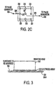
- Figure 2C shows an array of electrodes provided on an outer surface of the vibration plate that faces the skin, according to a third embodiment of the invention;
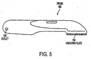
- Figure 3 shows a side view of a head of a probe that is used to provide both electrical and mechanical stimulation to the skin, in order to have a substance previously applied to the skin to be absorbed better, according to the invention;
- Figure 4 shows an electrical diagram of a pulse generator that provides electrical pulses to an array of electrodes disposed on a vibrating plate provided at a head-end of the probe, according to one possible configuration of an apparatus according to the invention;
- Figure 4A shows a train of square-wave pulses that are input to the pulse generator of Figure 4;
- Figure 4B shows a train of exponential pulses that are output from the pulse generator of Figure 4;
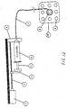
- Figure 5 shows one configuration of a hand-held probe that is used to provide both electrical and mechanical stimulation to the skin, according to one or more embodiments of the invention;
- Figure 6 shows a current generator connection according to a fourth embodiment of the invention;
- Figure 7 shows elements provided at the head portion of a probe, according to a fifth embodiment of the invention; and
- Figure 8 shows a front view of the head portion of the probe according to the fifth embodiment of the invention;
- Figure 9 shows a front view of the head portion of the probe according to an eighth embodiment of the invention;.
- Figure 10 shows a first section view of the head portion of the probe according to the eighth embodiment of the invention, whereby suction is not being applied to the skin;
- Figure 11 shows a second section view of the head portion of the probe according to the eighth embodiment of the invention, in which suction is being applied to the skin;
- Figure 12 shows a structure of an electroporation device according to a ninth embodiment of the invention;
- Figure 13 shows components used to couple electrodes and wires to a head of the electroporation device according to the ninth embodiment of the invention;
- Figure 14 shows a side view of the head of a probe used in an apparatus according to the ninth embodiment of the invention;
- Figure 15 shows a back view of the head of a probe, along with transformers shown, in an apparatus according to a tenth embodiment of the invention;
- Figure 16 shows a front view of the head of a probe used in an apparatus according to the tenth embodiment of the invention;
- Figure 17 shows a front view of the head of a probe having three electrodes, which is used in an,apparatus according to an eleventh embodiment of the invention;
- Figure 18 shows a back view of the head of a probe having three electrodes, along with transformers providing electronic pulses to the three electrodes, which is used in an apparatus according to the eleventh embodiment of the invention;
- Figure 19 shows staggered square-wave input pulses and exponential outputs pulses with respect to the three transformers which is used in an apparatus according to the eleventh embodiment of the invention; and
- Figure 20 shows a gauze pad provided between a probe (according to any of the embodiments of the invention) and a patient's skin, according to a twelfth embodiment of the invention.
- Preferred embodiments of the invention will be described in detail below, with reference to the accompanying drawings.
- Based on experimental tests on the skin, it has been found by the inventor that after one or more pulses are applied between two points on the skin, transpiration (or absorption) in the area between the two points on the skin increases. The pulses that give optimal results are exponential pulses that are generated by a charged capacitor that is discharged on at least two separate points on the skin.
- These experimental results have been utilized by the inventor in order to develop an apparatus and method that maintains the transpiration of the skin at a high level, so that the skin can readily absorb a gel, liquid, lotion, cream, or drug that is applied to the skin. The drug may be used to treat skin melanoma and/or cancerous tumors located just below the skin surface, for example.
- The apparatus according to an embodiment of the present invention applies a sequence of pulses over an area or skin, by using an array of electrodes that are placed in contact with the skin. The array of electrodes are provided on a vibrating plate at the head of a probe, such as a hand-held
probe 500 as shown in Figure 5. The array of electrodes may be a configured as shown in Figure 2A in a first embodiment, whereby odd rows of electrodes are electrically connected to each other, and thereby to a first output of a pulse generator 400 (see also Figure 4) via a first electrical connection. The even rows of electrodes are electrically connected to each other, and also to a second output of thepulse generator 400 via a second electrical connection. The array of electrodes on the vibrating plate may alternatively be configured as shown in Figure 2B in a second embodiment, whereby odd rows of round electrodes are electrically connected to each other, and thereby to the first output of thepulse generator 400 via a first electrical connection. The even rows of round electrodes are electrically connected to each other, and thereby to the second output of thepulse generator 400 via a second electrical connection. - The increase of the transpiration of the skin that is obtained by way of the present invention has the effect of increasing the absorption of liquids, creams, lotions, gels, or skin treatment drugs (or other kinds of drugs) that have been previously provided on the skin in the area between where the electrodes are applied to the skin.
- The electrical pulses that are applied on the skin in order to enhance the transpiration of the skin are pulses obtained by a discharge of a capacitor on the skin. A square-wave pulse input to a primary winding of the transformer 410 of Figure 4, with an output of the secondary winding of the transformer 410 being coupled to the skin by way of the electrodes, provides the same effect as a discharging capacitor. The exponential pulses are generated during the rising edge and falling edge of each square-wave input pulse that is input to the transformer 410 from a square-wave pulse generator, and have opposite sign (positive exponential pulse due to the rising edge of a square-wave input pulse, negative exponential pulse due to the falling edge of the same square-wave input pulse). With the use of such a
pulse generator 400 as shown in Figure 4, it is possible to apply a burst of separate pulses (e.g., 500 to 1500 per second) to the skin, with adjacent pulses being of opposite polarity and which provides a transpiration effect better than just providing one pulse or many Pulses of the same polarity to the skin. -
Switching transistor 430 provides square-wave pulses as shown in Figure 4A to the primary winding of the transformer 410, as shown in Figure 4. The pulses generated by thepulse generator 400 of Figure 4, when the load is a pure resistance (or inductive or other type of reactive load), is a sequence of exponential decay pulses of opposite symmetrical polarities, as shown in Figure 4B. Such a circuit that includes thepulse generator 400 provides an excellent coupling to the impedance of the skin. Moreover, the inductance of the transformer 410 together with the capacitance of the skin generates a resonant circuit, which is desirable to achieve an opening of the skin pores or membranes. - The voltage waveform is conveniently modified when applied to the skin due to the fact that the electrical equivalent circuit of the skin is a resistance and a capacitance in parallel. The resulting voltage waveform has a longer rise time (due to the RC time constant), and is dependent upon the capacitance of the skin, while maintaining the same peak current and the same exponential decay waveform.
- Such a circuit according to the first embodiment gives an advantage in comparison to traditional pulse generators that deliver pulses of a predefined value and shape of tension or current. By way of the present invention according to the first embodiment, it is possible to deliver higher energy value per pulse, and also at the same time avoid possible damage to the skin that would occur if high current amounts were applied to the skin. The circuit utilized in the first embodiment self adjusts the value of the current, tension and waveform shape. In particular, the impedance of the skin decreases after the first pulse is applied to the skin. In this way, the voltage of the first pulse is higher than subsequent pulses, since the impedance of the skin is higher at the time the first pulse is applied to the skin. The voltage of the second and following pulses applied to the skin decreases with the decreasing of the impedance of the skin, while maintaining the peak current at the same or almost the same value.
- Typical values of current and tension are provided herein. Case 1: load impedance of 10 kohm, peak voltage of 100 V, peak current of 10 milliamperes, pulse width of 220 microseconds. Case 2: load impedance of 1 kohm, peak voltage of 10 V, peak current of 10 milliamperes, pulse width of 220 microseconds, The pulses are preferably delivered in bursts, where the burst rate is the same as the mechanical vibration rate. A typical value of the burst rate (and mechanical rate) is between 40 Hz and 100 Hz.
- Normally, when a square wave is applied to the skin, due to the capacitive effect of the skin, it is possible to obtain about a three microsecond time constant exponential decay current. This is what happens when a square wave voltage is applied to a circuit that corresponds to a resistor in parallel with a capacitor.
- With such a circuit, only the peak current is enhanced, charging to a maximum allowable voltage the skin capacitance by applying an electrical energy equal to the magnetic energy of the transformer 410. This effect most likely provides for the opening of the cell membranes or pores of the skin (to achieve the transpiration effect) only during the time when each pulse is applied to the skin.
- The effect of applying the probe to the skin is that the skin vibrates due to the electrical pulses applied by way of the array of electrodes. The electrical pulses are preferably applied at a fixed frequency between 200 and 10,000 Hz (optimally at a frequency value between 2,500 to 3,000 Hz), and are grouped in a burst. The ON time of each burst is a fixed value between 5 to 50 milliseconds, and the OFF time between two consecutive bursts is a fixed value between 5 to 50 milliseconds (the preferred burst ON time is 10 milliseconds and the preferred OFF time between consecutive bursts is 10 milliseconds).
- As described above, the electrical pulses applied to the skin by way of the electrodes are preferably exponential pulses with peak-to-peak voltage of 160 V at a fixed frequency between 2,500 to 3,000 Hz. One way of providing such electrical pulses is by an electrical structure that corresponds to a
pulse generator 400 as shown in Figure 4, in which a transformer 410 is used as an element of thepulse generator 400. - The transformer 410, as well as the other elements of the
pulse generator 400, are preferably housed within theprobe 500 of Figure 5. - Referring back to Figure 4, the primary winding 420 of the transformer 410 is driven by a
transistor 430 that is switched on and off, and the secondary winding 440 of the transformer 410 is directly applied ,to the array of electrodes (see Figures 1A or 1B) with anelectrical resistance 450 provided therebetween. Theelectrical resistance 450 may be 200 Kohm or some value in that range (e.g., 100 Kohm to 500 Kohm), and is provided in order to avoid high voltages when the array of electrodes are not applied to the skin, so that in that case it operates as an open circuit. In such a situation, the peak-to-peak voltage is 400 V or thereabouts. - Along with the electrical pulses applied to the skin, a mechanical vibration is also provided to the skin in the first embodiment in order to increase the absorption of a substance that is applied on the skin.
- The absorption effect is enhanced by the simultaneous increase of transpiration, whereby the absorption effect is greatest when the mechanical vibration is synchronized in phase and in frequency with the electric pulse application. Thus, in the example discussed above, while the electrical burst of pulses (at 2,200 Hz) are provided to the skin at a burst ON/OFF frequency, e.g., 50 Hz, by way of an electrode array, the skin is also mechanically vibrated at the same frequency, e.g., 50 Hz, by way of the vibrating plate. The mechanical vibration and the electrical burst application are also preferably provided in phase with respect to each other, in order to increase the skin absorption effect. There are several well known ways to achieve this frequency and phase synchronization. In the preferred embodiments described herein, an optical sensor (not shown) detects the movement of the eccentric of a motor that is used to provide the mechanical vibrations (see Figures 1A and 1B, for example), and gates the burst of electrical pulses based on the detected movement.
- Thus, in the example discussed above, while the burst of electrical pulses are provided to the skin by way of the electrode array, the skin is also mechanically vibrated at the same frequency by way of the vibrating plate. The mechanical vibration and electrical pulse application is also preferably provided in phase with respect to each other, in order to increase the skin absorption effect.
- Moreover, the absorption effect is further enhanced when the mechanical vibration is applied orthogonal to the surface of the skin. While Applicant does not intend to be tied down to any particular theory of operation, one possible explanation of the physical phenomena of one 'or more embodiments of the present invention is that, while the electrical pulses "stretch" the skin, thus increasing periodically the diameter of the pores of the skin, at the same time the mechanical vibration "pumps" the substances (gel, liquid or cream) inside the skin (through the opened pores). The mechanical and electrical synchronization achieves the effect that the "pumping" action (due to the mechanical stimulation of the skin) takes place at the same instant in time that the pores are at their maximum "open" diameter (due to the electrical stimulation of the skin).
- The apparatus according to a first embodiment the present invention includes a probe having two main parts:
- A) a handle containing a power source (e.g., batteries) and a pulse generator; and
- B) a vibrating head containing components for generating the vibration and also containing an array of electrodes.
-
- The vibrating head, in a preferred configuration, includes a D.C. electrical motor for generating vibrations to the skin. Figures 1A and 1B show two different views of the D.C.
electrical motor 110, the rotating shaft of the D.C.electrical motor 110 is an eccentric 120 to thereby provide eccentric motion. The eccentric motion, during rotation of the D.C.electrical motor 110, generates a vibration onto the vibrating plate 130 (that is directly coupled to the D.C. electrical motor 110) that is at the same frequency of the rotation of the D.C. electrical motor 110 (e.g., 50 Hz or 60Hz or some other desired frequency). Other ways of causing vibrations in synchronization with the providing of electrical pulses to a patient may be contemplated while remaining within the scope of the invention. - As explained earlier, Figure 4 shows circuitry for providing electrical pulses to the array of electrodes shown in Figures 2A and 2B. The circuitry of Figure 4 corresponds to a
pulse generator 400, and is preferably disposed within the housing of theprobe 500 of Figure 5. The electrical pulses generated by thepulse generator 400, when those pulses are provided to the skin, preferably are exponential pulses with peak-to-peak voltage of 160 V at a frequency of between 2,500 Hz to 3,000 Hz. Of course, other peak-to-peak voltage values (e.g., 100 V to 200 V) and operating frequencies (50 Hz to 15,000 Hz) may be employed, while remaining within the scope of the invention as described herein. Alternatively, sawtooth or sinusoidal pulses may be provided to the electrodes, but exponential pulses appear to provide better skin transpiration results. - Figures 1A and 1B show the vibrating
plate 130 that is physical coupled to the D.C.electrical motor 110. The vibratingplate 130 preferably is 50 x 50 mm in size (other sizes are possible while remaining within the scope of the invention), where parallel metallic stripes are deposited on it as shown in Figure 2A, in order form the array of electrodes. The vibratingplate 130 is caused to vibrate at the same phase and frequency as the electrical pulses provided to the skin by way of the array of electrodes (disposed on the vibrating plate), in order to enhance the skin absorption effect. - As shown in Figure 2A, which shows a first embodiment of an
electrode array 210 that is provided on a skin-side surface of the vibratingplate 130, five parallelmetallic stripes 220 are provided, each preferably of a size of 50 mm x 4 mm. Each of the fiveelectrodes 220 are preferably 6 mm apart from adjacently-positioned electrodes. Theelectrodes 220 are alternately electrically connected (e.g., the first, third and fifth row are electrically connected to each other by way ofelectrical line 250; and the second and fourth rows are electrically connected to each other by way of electrical line 260). Other electrode array configurations are possible while remaining within the scope of the invention, such having a number of electrodes greater than two, such as having seven or eight electrodes. - Figure 2B shows a second embodiment of an electrode array that is provided on a skin-side surface of a vibration plate. In Figure 2B, there are provided 25
round electrodes 230 each of 4 mm diameter, each separated at least 6 mm from adjacently-positioned round electrodes. Theround electrodes 230 are alternately electrically connected to each other (e.g., the electrodes on the first, third and fifth rows are electrically connected to each other by way ofelectrical line 270; and the electrodes on the second and fourth rows are electrically connected to each other by way of electrical line 280). The spacing between theelectrodes 230 shown in Figure 2B may vary between 1 to 20 mm and the size of each of theelectrodes 230 may vary between 1 to 20 mm in diameter. - Figure 2C shows an array of electrodes provided on an outer surface of the vibration plate that faces the skin, according to the third embodiment of the invention. In Figure 2C, there are provided
electrodes 233 that are disposed on the periphery of the vibration plate, which are electrically coupled to each other, and which are electrically coupled to a first output of thepulse generator 400 by way of a firstelectrical connection 235. In Figure 2C, there is also provided a centrally-positionedelectrode 237, which is not electrically coupled to any other of the electrodes, and which is electrically coupled to a second output of thepulse generator 400 by way of a secondelectrical connection 239. - Figure 3 shows a side view of a vibrating
head 310 of a probe that is used to provide both electrical and mechanical stimulation to the skin according to an embodiment of the present invention, in order to have a substance previously applied to the skin be absorbed better. As shown in Figure 3, the vibratinghead 310 includes the array ofelectrodes 320 provided on a skin-side surface thereof. The array ofelectrodes 320 may be provided in a manner such as shown in either Figures 2A or 2B, for example. Between the array ofelectrodes 320 and theskin 330 there is provided a substance 340 to be absorbed, whereby the substance 340 has been previously applied to the skin 330 (e.g., applied to the skin between 30 seconds to 2 minutes before the probe is to be applied to the skin 330). Application of mechanical vibrations and electrical pulses enhances the absorption of the substance 340 into theskin 330. - Figure 5 shows one configuration of a hand-held
probe 500 that may be used to provide both electrical and mechanical stimulation to the skin, according to one or more embodiments of the invention. Theprobe 500 is configured to be readily held by one hand of a user. A bottom portion of theprobe 500, at which a user's hand is gripped thereon to thereby hold theprobe 500, may include anoutlet 510 for coupling an electrical cable to an electrical outlet (e.g., wall outlet), so as to provide A.C. voltage to theprobe 500 in that manner. Alternatively, battery power may be used, by way of batteries (not shown) disposed within the housing of theprobe 500. Battery power may be utilized when A.C. power is not readily available. Also, thepulse generator 400 of Figure 4 is preferably housed at the handle portion of theprobe 500. - The head portion of the
probe 500 is where the vibrating plate 130 (see Figures 1A or 1B) is provided, and also where the D.C. electrical motor 110 (see also Figures 1A or 1B) that provides the mechanical vibrations to the vibratingplate 130 is preferably provided housed within. The array of electrodes (see Figures 2A or 2B) are provided on an outer surface of the vibratingplate 130, thereby facing the skin of a user to be treated with theprobe 500. - A typical application time of the probe to the skin may be on the order to 10s of seconds up to several minutes.
- In a fourth embodiment, as shown in Figure 6, the output of the pulse generator 400 (see also Figure 4) is connected to a D.C.
current generator 610, which induces a iontophoresis effect in addition to the previously described skin absorption/transpiration effects. The iontophoresis effect is well known to those skilled in the art, and several ionthophoresis electrical generators are currently available in the market, either D.C. or D.C. pulsed. A D.C. current output by the D.C.current generator 610 is applied between the electrodes of the probe and a ground plate that is connected with the patient's body. Depending on the substance to be absorbed into the patient's skin, the patient ground plate connection is coupled to either the positive or the negative of the D.C.current generator 610, in a manner known to those skilled in the art. lnstead of using continuous D.C. current, there can alternatively be provided D.C. current pulses that have the same average current value as the continuous D.C. current case, and which have a duty cycle between 5 and 50% and a frequency between 10 and 5000 Hz. In such a case, the peak current of the D.C. current pulses is higher during the pulsed (ON) times. - In a fifth embodiment, as shown in Figures 7 and 8, a dispenser or
chamber 710, which is configured to hold liquid or cream orgel 720, is integrated in the vibrating head of the probe. The dispenser orchamber 710 is provided between an array ofelectrodes 705 and the vibratingplate 130. The burst of electrical pulses are applied by way of aconductive roller 740 that dispenses the liquid, and by the array ofelectrodes 705. A D.C. current as in the third embodiment can also be added between the array ofelectrodes 705 and the patient's body, to induce a iontophoresis effect as well. While the vibrating head is moved on the patient's skin, theroller 740 delivers the liquid or cream orgel 720 to the patient's skin. - The
chamber 710 in which theroller 740 is disposed in the vibrating head can be filled with a liquid, cream orgel substance 720 by way of a removable cap (not shown). In particular, the cap is removed (e.g., screwed off of the head of the probe), and then a user fills thechamber 710, through theliquid inlet 760, with thesubstance 720 to be provided to the patient's skin. The user then closes the cap (e.g., screws it back onto the liquid inlet 760) to thereby keep thesubstance 720 within thechamber 710 of the probe until it is ready to be applied to the patient's skin by way of theroller 740. - Figure 8 shows a front view of the
electrodes 705, which are shown as two stripe electrodes that are electrically connected to each other by way ofelectrical connection 820. Of course, other types of electrode arrays, such as those shown in Figures 2A and 2B, can alternatively be used in this fifth embodiment. The exposedsurface 830 of theroller 740 that applies the substance to the patient's skin, is shown in Figure 8. Dispensinggaps 840 are also shown in Figure 8, whereby thesegaps 840 allow the liquid, cream orgel substance 720 in thechamber 710 to gradually come out of thechamber 710 and thereby be applied to the patient's skin by way of theroller 740. - In a sixth embodiment of the invention, an apparatus for enhancing absorption of the skin includes an array of electrodes, and a pulse generator that is electrically coupled to the array of electrodes. The disposition of the array of electrodes may be any of the dispositions shown in Figures 2A - 2C, for example. In a preferred implementation of the sixth embodiment, electrical pulses outputted by the
pulse generator 400 to the array of electrodes are a sequence of exponential pulses, such as the pulse train shown in Figure 4B. The exponential electrical pulses are applied to the skin by way of the array of, electrodes and are generated by the secondary winding of a high voltage transformer with the primary winding driven by a square wave voltage, as seen by Figures 4, 4A and 4B. - In the sixth embodiment, unlike the previous embodiments, a vibrating head is not utilized, but rather skin absorption enhancement is obtained just by the providing of the electrical pulses to the skin by way of the array of electrodes. The array of electrodes according to the sixth embodiment are provided on a plate at the head of the probe, whereby the head and the plate do not vibrate. Thus, in the sixth embodiment, the structure as shown in Figures 1A and 1B would not be utilized, but rather just a plate for holding the electrodes in place at the head of the probe would be needed.
- In a seventh embodiment, a vibrating head is utilized, as in the first through fifth embodiments, but where the vibrating head is capable of being turned on or off, by way of a control (e.g., switch) provided on the probe. The control can readily be manipulated by an operator of the probe, in order to treat a patient.
- An eighth embodiment of the invention is described below, with reference to Figures 9-11. Figure 9 shows a front view of a
head 800 of a probe, whereby that view shows the portion of the probe that is applied to the skin of a patient. Figure 10 shows a section view taken along an axis of one belt, and Figure 11 shows a section view taken at the middle of the head of the probe. - The eighth embodiment provides for a fairly even absorption under the skin of a substance previously applied to the skin, such as collagen previously applied to the skin. In the eighth embodiment, a
head 800 of a probe to be applied to the skin includes a vibratingplate 810, avacuum chamber 820,rollers 830, andbelts 840 disposed around therollers 830. Therollers 830 are conductive rollers, whereby therollers 830 are electrically coupled to electrodes (see Figures 2A through 2C, for example) provided on the vibratingplate 810. As in the other embodiments, a pulse generator (see Figure 4, for example) is electrically coupled to the electrodes on the vibratingplate 810, in order to provide electrical pulses to the patient's skin (by way of the conductive rollers). - In the eighth embodiment, the
rollers 830 are separated from each other by around 40 mm. Of course, other separation distances are possible, while remaining within the scope of the invention (e.g., 20 mm to 80 mm separation). Therollers 830 are disposed at one end of thevacuum chamber 820, whereby thevacuum chamber 820 includes an opening that is coupled to apipe 845 that is in turn coupled to avacuum pump 855. - When the
vacuum pump 855 is operated, thevacuum chamber 820 generates a suction effect on theskin 850, thereby enabling a stronger contact between therollers 830 and theskin 850, and thereby generating an additional massaging effect to theskin 850, in addition to the vibrations generated by the vibratingplate 810. On opposite ends of therollers 830 are thebelts 840, which are preferably rubber belts. Thebelts 840 are used in order to avoid direct friction between theskin 850 and the body of thevacuum chamber 820. - The eighth embodiment provides good skin absorption results and decreases the appearance of cellulite on the skin after application of a substance for reducing cellulite is applied to the skin. Such a substance for reducing cellulite that can be applied to the skin may be jarulon acid, for example. Such a substance could also be previously spread on the skin and absorbed by the skin utilizing one of the previously-described embodiments.
- Also, while the eighth embodiment has been described as having a vibrating plate, as in the first through fifth embodiments, a non-vibrating plate as in the sixth and seventh embodiments (when the vibrating plate is turned off) may be utilized in an alternative configuration. In that case, the plate disposed above the vacuum chamber is non-vibrating, and contains electrodes disposed therein.
- A ninth embodiment of the invention will be described in detail hereinbelow with reference to Figures 12-14. The ninth embodiment includes a
motor 1, ascrew 2, aslide 3, aframe 4, apiston 5, asyringe 6, a pipe (or tubing) 7, acentral electrode 8, and circumferential electrodes 9 (that are disposed outside of the central electrode 8) on ahead 10. Thehead 10 is a head portion of a probe, such a probe shown in Figure 5 in the previous embodiments (except for the fifth embodiment, whereby the substance is disposed within a chamber within the head that is adjacent to the electrode plate, and thus a syringe would not be needed in that case), for example. - in the ninth embodiment, the
syringe 6 is preferably a disposable, single-use syringe, which is positioned adjacent to the probe (only thehead 10 of the probe is shown in Figure 12, whereby the rest of the probe is hidden behind thehead 10 in the view provided in Figure 12). Thesyringe 6 is inserted or fitted onto theframe 4, and does not move relative to theframe 4. For example, theframe 4 may be placed on a table next to a bed on which a patient to be treated is located. - The
piston 5 is operable to move relative to theframe 4, whereby the movement is caused by themotor 1, thescrew 2, and theslide 3, which operate together as a moving means. With the configuration shown in Figure 12, the probe is free-standing and can be moved a certain amount (e.g., 1 to 10 feet, depending on the length of the tube 7) relative to the frame 4 (while maintaining a coupling to thesyringe 6 by way of thetube 7 that couples thesyringe 6 with thehead 10 of the probe). That way, the probe can be moved around to treat different areas of a skin of a patient lying on a bed, while the frame containing thesyringe 6 rests in place on a table next to the bed. In an alternative configuration, the probe and thesyringe 6 can both be mounted on theframe 4, as a single-block construction. In this configuration, the entire frame is moved to different areas of the patient's skin, to thereby treat the patient by way of a probe that is inserted in the frame. The head of the probe extends out from one end of the frame, so that it can be placed against the patient's skin. - In a preferred implementation, the
motor 1 is powered by a different power source than the source providing power to the probe. However, in a different implementation, themotor 1 and the probe may be powered by the same power source, - A tube or
pipe 7 is used to connect thesyringe 6 with thehead 10 of the probe. Thetube 7 is preferably a disposable, single-use component, and may be a flexible plastic tubing, for example. Thehead 10 is preferably a vibrating head, such as described earlier with respect to other embodiments. In an alternative configuration, thehead 10 does not vibrate, and only electrical pulses are provided to the skin (so as to electroporate the skin to thereby absorb the substance provided to the skin by way of thesyringe 6 and tube 7) in this alternative configuration. Thetube 7 is preferably 0.5 to 3 millimeters in diameter, and is sized so as to allow a liquid or cream-like substance to flow through thetube 7, and exit thetube 7 at a second end opposite a first end of thetube 7 that is coupled to thesyringe 6. Such a substance to be applied to the skin may include water-based collagen, water-based elastine, and anesthetic, or other type of drug, just to name a few. - Referring now to Figure 14, the
tube 7 couples to thehead 10 by way of agroove 12 that is located at an end of thehead 10 and that is provided all the way to a groove 11 that surrounds thecentral electrode 8. Thegroove 12 is sized so as to accept thetube 7 fitted therein to provide a snug fit, whereby thetube 7 is preferably fitted within thegroove 12 by feeding thetube 7 within thegroove 12 from the end of thehead 10 where one end of thegroove 12 is disposed. In the ninth embodiment, the size of thegroove 12 is such that thetube 7 does not extend above the upper surface of the head 10 (where theelectrodes tube 7 extends slightly below the upper surface (plate) of thehead 10. That way, thetube 7 will not be felt by the patient when thehead 10 of the probe is moved along the skin of the patient during a treatment. Preferably, thetube 7 will not be in contact with the skin of the patient during treatment of the patient by way of a method and/or apparatus according to the ninth embodiment. The top surface of thehead 10 preferably has a plate-like configuration, so as to provide a smooth feeling to the patient's skin. - On the top surface of the
head 10 there are provided onecentral electrode 8 and a plurality ofcircumferential electrodes 9 disposed around thecentral electrode 8. The groove or trough 11 surrounding thecentral electrode 8 is preferably 1 mm wide, whereby the groove 11 is coupled to one end of thegroove 12 in which a portion of thetube 7 is disposed. That way, when a substance is flowed out of the syringe 6 (by way of action by themotor 1, thescrew 2 and the slide 3), the substance flows through the tube 7 (disposed within the groove 12) and thereby into the groove 11. The substance collects within the groove 11 surrounding thecentral electrode 8, and is absorbed by the skin during an electroporation treatment (using electrical pulses and mechanical vibrations) by way of the ninth embodiment. When the top surface (plate) of thehead 10 is placed in contact with the patient's skin, the substance within the groove 11 comes into contact with the patient's skin, and is absorbed by the skin. - Although eight
circumferential electrodes 9 are shown in Figure 12, the invention according to the ninth embodiment can operate with different numbers ofcircumferential electrodes 9. For example, a minimum of twocircumferential electrodes 9, disposed opposite from each other (with thecentral electrode 8 disposed therebetween), may be utilized in a different configuration. Also, fourcircumferential electrodes 9 and more than eightcircumferential electrodes 9 may be utilized in other different configurations (e.g., 16 electrodes, 32 electrodes, or an odd number, such as three, five, or seven, circumferential electrodes surrounding the central electrode 8) of the ninth embodiment. - A pulse generator, such as the one shown in Figure 4 (see also Figures 4A and 4B), is used to provide electrical pulses to the
electrodes head 10 of the probe. As explained earlier, the preferred shape of the electrical pulses is an exponential shape, as shown in Figure 4B. Alternatively, sinusoidal or sawtooth waveforms may be provided, but exponential pulses provide a better skin transpiration effect. Operation of the pulse generator that may be utilized in the ninth embodiment has been described in detail with respect to the first embodiment described previously, and will not be described here for sake of brevity. - One of the two outputs of the pulse generator (see Figure 4) is connected to the
central electrode 8, and the other of the two outputs of the pulse generator is connected to one of thecircumferential electrodes 9. Thecircumferential electrodes 9 are coupled to each other electrically on the back side of the head (see dashed line in Figure 2C), so that each of the electrical pulses provided on the other of the two outputs of the pulse generator is provided to all of thecircumferential electrodes 9 simultaneously. - The voltage of the electrical pulses provided to the skin from each of the eight
circumferential electrodes 9 can be considered as a "ground" with respect to the voltage of the electrical pulse provided to the skin from the onecentral electrode 8. Since thecentral electrode 8 carries more electrical current than each of the eightcircumferential electrodes 9, thecircumferential electrodes 9 act like a ground connection, whereby the electrical current carried by each of the eightcircumferential electrodes 9 is approximately eight times less than the electrical current carried by thecentral electrode 8. - The
piston 5 of thesyringe 6 is moved by themotor 1, which is a DC electric motor in a preferred implementation. Themotor 1 is connected to thescrew 2, which moves thepiston 5 by way of theslide 3 that is attached to thescrew 2 at a particular location on thescrew 2. When thehead 10 of the probe is positioned on a patient's skin, electrical pulses are delivered to theelectrodes piston 5 of thesyringe 6 is moved by themotor 1 in order to deliver the liquid or cream-like substance (or drug) from within thesyringe 6 to the patient's skin. The liquid, cream or drug is preferably provided to the patient's skin in a slow, controlled manner, to allow the substance to be properly absorbed within the skin. For example, a water-based collagen, a water-based elastine, an anesthetic, or other type of drug may be provided within thesyringe 6, to then be provided to the skin of a patient (to be absorbed therein) by way of the method and apparatus according to the ninth embodiment. - The enhancement of the skin absorption by electrical pulses applied to the skin, and also by mechanical vibrations applied to the skin at the same time in a synchronous manner (see description of the vibrating plate with respect to other embodiments) of the ninth embodiment, enables the absorption of a drug or other type of substance delivered by way of the
syringe 6. A typical drug absorption quantity is 1 cubic centimeter in one to five minutes, by using the method and apparatus according to the ninth embodiment. In this regard, the timing of the movement of thepiston 5 is such that the correct amount of substance is output from thesyringe 6 during a treatment of a patient, whereby when the probe is turned on, this event will provide a trigger signal to themotor 1 to start to operate. Operation of themotor 1 will in turn cause the substance within thesyringe 6 to be pushed out of thesyringe 6, and into thegroove 12 surrounding thecentral electrode 8. - The substance is introduced within the syringe at a previous time, so that the
syringe 6 with the substance provided therein can then be attached to theframe 4, coupled to thetube 7, and thereby provide an apparatus that can introduce drugs and/or other substances to the skin of a patient, by way of a probe having ahead 10 withelectrodes head 10. As explained earlier, thehead 10 vibrates, so that both electrical and mechanical vibrations are provided to the patient's skin at a same time the drug or other substance is provided to the patient's skin (by way of the substance disposed within the trough or groove 12 being in contact with the patient's skin during a treatment of the patient). In an alternative configuration, which provides a skin transpiration effect not as good as using both mechanical vibrations and electrical pulses, only electrical pulses are provided to a patient's skin (the head does not vibrate). This configuration is cheaper to build, and may be suitable for certain instances. - The
motor 1,screw 2,slide 3,piston 5,syringe 6,frame 4 andtube 7 may be coupled to different types of probes, in order to provide an apparatus for skin absorption enhancement and transdermal drug delivery. For example, any of the probes described: with respect to the other embodiments (except those that have the substance stored in a container within the head of the probe) may be utilized with the components described above. Also, the structure for moving a substance out of thesyringe 6 may be accomplished by ways other than the screw/slide/motor "moving means" described with respect to Figure 12, while remaining within the scope of the invention. - Figure 13 shows a back view of the
head 10, whereby components used to couple theelectrodes electrodes motor 1310, which includes an eccentric 1320 coupled to an output of themotor 1310, is used to provide mechanical vibrations to thehead 10, so that the apparatus provides both electrical and mechanical vibrations to a patient's skin at the same time. These mechanical vibrations are preferable synchronized with the electrical pulses, as described earlier with respect to other-described embodiments of the invention. - The
electrodes head 10.Washers 1330 andscrews 1340 are utilized toelectrically couple wires electrodes central electrode 9, and wire 1355 (that has one end coupled to the other of the two outputs of the pulse generator as shown in Figure 4, for example) is electrically connected to thecircumferential electrodes 8.Resistor 1365 is provided between thewires housing 1375 which is coupled to thehead 10 by way ofscrews 1380. The eccentric 1320 moves within thehousing 1375, thereby causing vibrations that are translated to thehead 10 of the probe. - A tenth embodiment of the invention will be described herein with respect to Figures 15 and 16. The tenth embodiment is similar to the ninth embodiment, but utilizes a different configuration for the head, as well as providing a plurality of transformers (see Figures 4, 4A and 4B). Figure 15 shows a back view of the
electrodes 1500 disposed on ahead 1510 of a probe, and Figure 16 shows a front (skin-side) view of theelectrodes 1500, whereby each electrode has a groove ortrough 1530 surrounding it. Eachgroove 1530 has an outlet that extends to an edge of thehead 1510, to thereby allow arespective tube 1550 to be fitted therein, so as to provide an amount of substance from thesyringe 6 to thegrooves 1530. That way, thetubes 1550 do not extend above the top surface of thehead 1510. As an alternative to the multi-port tube configuration shown in Figure 16, a number of syringes equal in number to the number of electrodes may be provided, with a tube provided to couple a syringe to an electrode. - In the tenth embodiment, each
electrode 1500 is active and is connected to its own pulse transformer 1560A - 1560I. The substance from thesyringe 6 is provided togrooves 1530 surrounding each of theelectrodes 1500. The electronic pulses are provided to each of theelectrodes 1530 from the respective pulse transformers 1560A - 1560I, whereby transformers 1560C, 1560E, 1560G and 1560I provide positive pulses to their respective electrodes, and whereby transformers 1560A, 1560B, 1560D, 1560F and 1560H provide negative pulses to their respective electrodes at the same time, for the nine electrode configuration. More particularly, transformers 1560C, 1560E, 1560G and 1560I have their primary and secondary windings connected in phase, and transformers 1560A, 1560B, 1560D, 1560F and 1560H have their primary and secondary windings Connected 180 degrees out of phase (see oppositely-positioned dots for those transformers in Figure 15). If a square wave is applied to all of the primary windings of the transformers at the same time and when there is a positive transition from low to high, the transformers with their primary and secondary windings in phase with each other will output a positive exponential pulse, and the transformers with their primary and secondary windings 180 degrees out of phase with each other will output a negative exponential pulse. - In the tenth embodiment, it is preferable that a first group of electrodes receive a positive pulse at a same time a second group of electrodes (equal or nearly equal in number to the first group, preferably) receive a negative pulse, to provide a good skin transpiration effect. The type of pulses, the burst duration, the frequency, etc., are similar to the embodiments described earlier. Also, the tenth embodiment may include a mechanical vibration that is applied to the patient's skin at the same time the electrical pulses are applied to the patient's skin, in a manner described previously.
- In an eleventh embodiment, a plurality of transformers are respectively provided to output electrical pulses to a plurality of electrodes disposed on a head portion of a probe, whereby the plurality of transformers provide separate and independent pulse bursts to their respective electrodes. For example, each of the pulse generators in the eleventh embodiment may have different phase shift amounts within a range of from 0 degrees to 360 degrees. In this regard, the output pulses from the transformers are synchronized with each other, to have a particular out-of-phase relationship with respect to each other.
- One example of an electrode array according to the eleventh embodiment is shown in Figures 17, 18 and 19. This example provides a three electrode configuration, with no central electrode. Referring now to Figure 17, which shows a front side of the
head 10,electrodes 1700 are respectively coupled via tube 1710 to asyringe 6, to receive a substance in agroove 1720 surrounding each of theelectrodes 1700. Like the previously-described embodiments, as shown in Figure 14, a groove or path to an end of thehead 10 is provided, in order to fit the tube 1710 snugly within it so that the tube 1710 does not extend above the upper surface (plate) of thehead 10 that makes contact with a patient's skin. - Referring now to Figure 18, which shows a back side of the
head 10,transformers electrodes 1700 coupled to each transformer. Figure 19 shows the input square wave pulses that are provided to each transformer, whereby the square wave pulses that are input totransformer 1810C are delayed a certain amount (e.g., 30 degrees) with respect to the square pulses that are input to transformer 1810B, which in turn are delayed a certain amount (e.g., 30 degrees) with respect to the square wave pulses that are input totransformer 1810A. This can readily be done by providing the trigger "IN" signal to each of therespective transformers - With the three-electrode and three-pulse-generator configuration as shown in Figures 17-19, it is possible to provide a 120 degree phase shift with respect to the signals output by the three pulse generators (e.g., one signal output at 0 degrees, one signal output at 120 degrees, and one signal output at 240 degrees). This provides a rotation of the electric field between the
electrodes 1700 in a manner similar to what happens with a rotation of a three-phase motor. More generally, in the eleventh embodiment, using a number "n" of electrodes and "n" pulse generators, one of ordinary skill in the art will understand that one can devise any particular type of electric field distribution on the skin surface to be treated by way of an apparatus according to the eleventh embodiment, as desired. - A twelfth embodiment of the invention will be described below with reference to Figure 20. In the twelfth embodiment, a probe 2010 is used to provide a skin-absorbing substance to the skin. in that regard, the probe 2010 may be a probe according to any of the previous embodiments of the invention described earlier in this application. As shown in Figure 20, the probe 2010 has a vibrating head 2020 and an electrode array 2030 provided at an end portion of the vibrating head 2020. In the twelfth embodiment, gauze 2033 is provided between the head 2020 of the probe 2010 and the patient's skin 2040. Preferably, the gauze 2033 is a pad having a same size (or substantially the same size) as the head 2020 of the probe 2010 or larger in order to cover the treatment area where the head 2020 is supposed to be moved. In a preferred implementation, the gauze 2033 is a pad (e.g., rectangular or square shaped, with a thickness between 0.1 to 1 mm) that is commercially available on the market. With the gauze 2033 provided between the probe 2010 and the patient's skin 2040, the probe 2010 does not come into direct contact with the patient's skin 2040. The gauze 2033 allows for the probe 2010 to be moved over the patient's skin 2040 in an easier manner and with less friction than in a case where the gauze 2033 is not utilized. Also, the inventor has found out that the use of the gauze 2033 provides for a more even application of the skin-absorbing substance 2035 to the patient's skin 2040. As an alternative to gauze, other types of pads, such as a cotton tissue or a synthetic (e.g., nylon) tissue, may be used between the patient's skin 2040 and the probe 2010. All of these pads have a characteristic of sufficient porosity to allow the skin-absorbing substance 2035 to pass from (its container within) the head 2020 of the probe 2010 (for those embodiments in which the skin-absorbing substance 2035 is stored within the head 2020 of the probe 2010) and through the pad 2033 and thereby onto the patient's skin 2040.
- In the present invention according to the twelfth embodiment, an important feature is that gauze is provided between the head of the probe and the patient's skin. In one possible implementation, the gauze is affixed to the head of the probe and not to the patient's skin. In another possible implementation, the gauze is affixed to the patient's skin and not to the head of the probe. With either implementation, one obtains a more even distribution of the skin absorbing substance to the skin (as compared to the case whereby no gauze is utilized), and at the same time allows the head of the probe to be moved across the patient's skin (to treat a particular region of the patient's skin) with less friction (as compared to the case whereby no gauze is utilized). The gauze can be releasably affixed to the patient's skin in one possible implementation of the twelfth embodiment in a variety of ways, such as by using medical tape. The gauze can be releasably affixed to the head of the probe in another possible implementation of the twelfth embodiment in a variety of ways, such as by rubber-banding the gauze pad to the head of the probe (with 'the rubber band gripped around the sidewalls of the head of the probe), or by using adhesive tape to adhere the peripheral edges of the gauze pad to the sidewalls of the head of the probe, or by providing a gauze pad with an outer (e.g., plastic) sheath that allows the gauze pad to be easily fitted onto and off of the head of the probe. In any of these cases, the gauze can be readily removed from the patient's skin or the head of the probe, and disposed after use.
- Experimental results of the application of the several embodiments of the skin absorption apparatus described hereinabove to the skin demonstrated that a noticeable variation of results and rate of absorption of substances occurred. The analysis was carried out over an area of skin previously dermabraded with a standard microdermabrader available on the market and an adjacent area not previously dermabraded. This analysis demonstrated that the results obtained in the dermabraded area are fairly constant and reproducible while the results in the non-dermabraded area are variable and somewhat inconsistent. This inconsistency is due to the fact that the stratum corneum (also referred to as the horny or dead outermost layer of the epidermis) of the skin acts like a barrier to the absorption of the substances applied to the skin, and moreover it increases the electrical resistance of the skin, thereby somewhat decreasing the absorption effect of the skin absorption treatment according to the invention.
- The thickness of the stratum corneum is variable from person to person, and moreover it is variable from time to time in the same person. This induces a variability that makes it difficult to come up with a standard application time of the skin absorption apparatus according to the various embodiments of the invention. For this reason, according to yet another embodiment of the invention, a skin absorption treatment method includes a microdermabrasion performed before the application of the skin absorption apparatus in order to give more reproducible and more constant results as compared to the embodiments in which a microdermabrasion is not first performed. The microdermabrasion to be performed prior to the skin absorption treatment may be one described in Various U.S. patents assigned to Mattioli Engineering, Ltd., such as U.S. Patent Nos. 6,322,568 and 6,039,745, each of which are incorporated in their entirety herein by reference, or other types of dermabrasion treatments conventionally known.
- Preferably, the dermabrasion treatment is performed for three minutes in order to remove a 100 micron layer of the corneum status of the skin in an area to be later treated with a skin absorption enhancement device according to one of the embodiments of the invention. Ideally, the skin absorption treatment is performed soon after (e.g., within 5 minutes) bf the completion of the dermabrasion treatment. Of course, other time lengths of dermabrasion treatment, depth of corneum status removal, and time between the dermabrasion treatment and the skin absorption treatment, may be contemplated while remaining within the scope of the invention as described hereinabove.
- Different embodiments of the present invention have been described according to the present invention. Many modifications and variations may be made to the techniques and structures described and illustrated herein without departing from the spirit and scope of the invention. Accordingly, it should be understood that the apparatuses described herein are illustrative only and are not limiting upon the scope of the invention.
Claims (4)
- A treatment method for enhancing absorption of substances provided on a surface of a patient's skin, comprising:wherein the gauze pad allows for the probe to be moved over the surface of the patient's skin with less friction than if no gauze pad is used.a) applying a substance to the surface of the patient's skin by way of a probe that provides at least one of: i) electrical pulses to the skin surface, and ii) vibrational pulses to the skin surface, in order to cause absorption of the substance within the patient's skin; andb) at the same time as step a), providing a gauze pad between the probe and the patient's skin,
- The treatment method according to claim 1, wherein the gauze pad allows for the substance to be applied to the skin surface in a substantially even manner.
- A system for enhancing absorption of a substance provided on a skin region of a patient, comprising:wherein at least one of the sequence of bursts of electrical pulses and the mechanical vibrations are provided to the skin region at the same time the substance is provided to the head of the probe, in order to :enhance absorption of the substance applied to the skin region when the head of the probe is provided to the skin region of the patient with the gauze pad disposed therebetween.a gauze pad; anda probe configured to provide the substance to the skin region of the patient, the probe comprising:an array of electrodes provided on a head of the probe;means for holding the substance to be provided on the skin region of the patient;a pulse generator configured to generate a sequence of bursts of electrical pulses to the array of electrodes that are placed adjacent to the skin;a vibrating unit configured to provide mechanical vibrations to the head of the probe; andmeans for providing the substance from the holding means to the head of the probe,
- The system according to claim 3, wherein the gauze pad for movement of the probe on the skin region of the patient with less friction than would be the case if no gauze pad was utilized.
Applications Claiming Priority (2)
| Application Number | Priority Date | Filing Date | Title |
|---|---|---|---|
| US397533 | 1982-07-12 | ||
| US10/397,533 US7010343B2 (en) | 2001-04-06 | 2003-03-27 | Method and apparatus for skin absorption enhancement and transdermal drug delivery |
Publications (2)
| Publication Number | Publication Date |
|---|---|
| EP1462145A1 true EP1462145A1 (en) | 2004-09-29 |
| EP1462145B1 EP1462145B1 (en) | 2012-01-04 |
Family
ID=32824976
Family Applications (1)
| Application Number | Title | Priority Date | Filing Date |
|---|---|---|---|
| EP04290817A Expired - Lifetime EP1462145B1 (en) | 2003-03-27 | 2004-03-26 | Apparatus for skin absorption enhancement and transdermal drug delivery |
Country Status (3)
| Country | Link |
|---|---|
| US (2) | US7010343B2 (en) |
| EP (1) | EP1462145B1 (en) |
| AT (1) | ATE539794T1 (en) |
Cited By (1)
| Publication number | Priority date | Publication date | Assignee | Title |
|---|---|---|---|---|
| FR2929109A1 (en) * | 2008-04-01 | 2009-10-02 | Patrick Fouchier | Stimulation system for stimulating acupuncture points of body of patient, has cylindrical metallic probe element, which contacts with zone i.e. surface, of skin of patient, by interposing film of liquid between element and skin surface |
Families Citing this family (31)
| Publication number | Priority date | Publication date | Assignee | Title |
|---|---|---|---|---|
| US7520875B2 (en) * | 2001-04-06 | 2009-04-21 | Mattioli Engineering Ltd. | Method and apparatus for skin absorption enhancement and transdermal drug delivery |
| US7496401B2 (en) * | 2001-04-06 | 2009-02-24 | Mattioli Engineering Ltd | Method and apparatus for skin absorption enhancement and transdermal drug delivery |
| US7083580B2 (en) * | 2001-04-06 | 2006-08-01 | Mattioli Engineering Ltd. | Method and apparatus for skin absorption enhancement and transdermal drug delivery |
| US9283597B2 (en) * | 2002-12-02 | 2016-03-15 | Cfd Research Corporation | Miniaturized electrothermal flow induced infusion pump |
| US20060100555A1 (en) * | 2004-11-05 | 2006-05-11 | Cagle Merry M | Apparatus and system for treating cellulite |
| WO2007038252A2 (en) * | 2005-09-22 | 2007-04-05 | Key Douglas J | Methods and compositions for treating skin lines and wrinkles and improving skin quality |
| US20070232966A1 (en) * | 2005-11-30 | 2007-10-04 | Robert Applebaum | Apparatus for skin and muscle treatment |
| US7853320B1 (en) | 2007-05-31 | 2010-12-14 | Purdue Pharma L.P. | Transdermal device having mechanical assist for porator-to-skin contact |
| US8095213B1 (en) * | 2007-05-31 | 2012-01-10 | Purdue Pharma L.P. | Transdermal patch |
| US8047399B1 (en) | 2007-07-05 | 2011-11-01 | Purdue Pharma L.P. | Dispenser for transdermal devices |
| US20090299266A1 (en) * | 2008-06-02 | 2009-12-03 | Mattioli Engineering Ltd. | Method and apparatus for skin absorption enhancement and transdermal drug delivery |
| JP5653918B2 (en) | 2008-07-30 | 2015-01-14 | エコーレ ポリテクニーク フェデラーレ デ ローザンヌ (イーピーエフエル) | Apparatus and method for optimized stimulation of neural targets |
| EP3563902B1 (en) | 2008-11-12 | 2021-07-14 | Ecole Polytechnique Fédérale de Lausanne | Microfabricated neurostimulation device |
| CA2782710C (en) | 2009-12-01 | 2019-01-22 | Ecole Polytechnique Federale De Lausanne | Microfabricated neurostimulation device and methods of making and using the same |
| JP5927176B2 (en) | 2010-04-01 | 2016-06-01 | エコーレ ポリテクニーク フェデラーレ デ ローザンヌ (イーピーエフエル) | Device for interacting with neural tissue and methods of making and using it |
| US20150257970A1 (en) * | 2011-02-17 | 2015-09-17 | Martin Mücke | Device and method for reducing pain |
| WO2013190537A1 (en) * | 2012-06-18 | 2013-12-27 | Michael Tavger | Method and system for delivering solution into the pores of recipient human skin |
| EP3476430B1 (en) | 2014-05-16 | 2020-07-01 | Aleva Neurotherapeutics SA | Device for interacting with neurological tissue |
| US11311718B2 (en) | 2014-05-16 | 2022-04-26 | Aleva Neurotherapeutics Sa | Device for interacting with neurological tissue and methods of making and using the same |
| US9474894B2 (en) | 2014-08-27 | 2016-10-25 | Aleva Neurotherapeutics | Deep brain stimulation lead |
| US9403011B2 (en) | 2014-08-27 | 2016-08-02 | Aleva Neurotherapeutics | Leadless neurostimulator |
| EP3397335B1 (en) * | 2015-12-28 | 2022-08-03 | Inovio Pharmaceuticals, Inc. | Electroporation device with improved signal generator |
| EP3411111A1 (en) | 2016-02-02 | 2018-12-12 | Aleva Neurotherapeutics SA | Treatment of autoimmune diseases with deep brain stimulation |
| US11251635B2 (en) | 2017-12-19 | 2022-02-15 | Welch Allyn, Inc. | Vital signs monitor with a removable and dischargable battery |
| US10702692B2 (en) | 2018-03-02 | 2020-07-07 | Aleva Neurotherapeutics | Neurostimulation device |
| US11730668B2 (en) | 2020-06-29 | 2023-08-22 | Therabody, Inc. | Vibrating therapy system and device |
| US11219762B2 (en) | 2019-03-04 | 2022-01-11 | Vitality Concepts International Ltd. | Therapeutic device for female genital predictive permeation |
| CN115734778B (en) | 2020-06-29 | 2024-04-12 | 席拉博迪股份有限公司 | Vibration therapy system and apparatus |
| US11564863B2 (en) | 2020-06-29 | 2023-01-31 | Therabody, Inc. | Cooling attachment module for facial treatment device |
| USD976431S1 (en) | 2021-03-02 | 2023-01-24 | Therabody, Inc. | Facial treatment device |
| USD1004793S1 (en) | 2021-03-02 | 2023-11-14 | Therabody, Inc. | Facial treatment device |
Citations (2)
| Publication number | Priority date | Publication date | Assignee | Title |
|---|---|---|---|---|
| US6302874B1 (en) * | 1998-07-13 | 2001-10-16 | Genetronics, Inc. | Method and apparatus for electrically assisted topical delivery of agents for cosmetic applications |
| US20030014081A1 (en) * | 2001-04-06 | 2003-01-16 | Mattioli Engineering Ltd. | Method and apparatus for skin absorption enhancement and transdermal drug delivery |
Family Cites Families (55)
| Publication number | Priority date | Publication date | Assignee | Title |
|---|---|---|---|---|
| GB1077143A (en) | 1964-09-30 | 1967-07-26 | Norman Alexander Macleod | Improvements in an applicator for use in the therapeutic treatment of skin |
| DE2242079A1 (en) | 1972-08-26 | 1974-03-07 | Bruns Dieter | DEVICE FOR THE SIMULTANEOUS APPLICATION OF MASSAGE MOVEMENTS AND THERAPEUTICALLY EFFECTIVE IRRITATION CURRENTS |
| US4141359A (en) | 1976-08-16 | 1979-02-27 | University Of Utah | Epidermal iontophoresis device |
| US4301794A (en) | 1978-10-18 | 1981-11-24 | Robert Tapper | Method for iontophoretic treatment |
| US5135479A (en) | 1983-08-18 | 1992-08-04 | Drug Delivery Systems, Inc. | Programmable control and mounting system for transdermal drug applicator |
| CA1262564A (en) * | 1983-09-01 | 1989-10-31 | Minoru Sasaki | Iontophoresis device |
| US4822470A (en) | 1987-10-09 | 1989-04-18 | Baylor College Of Medicine | Method of and apparatus for cell poration and cell fusion using radiofrequency electrical pulses |
| DE3739563C1 (en) | 1987-11-22 | 1989-04-13 | Fresenius Ag | Infusion syringe pump |
| JP2706465B2 (en) | 1988-04-27 | 1998-01-28 | 株式会社寺西電機製作所 | Portable massage machine |
| US4887594A (en) | 1988-06-09 | 1989-12-19 | Louis Siegel | Vibratory medicator |
| EP0346513A1 (en) | 1988-06-15 | 1989-12-20 | Etama Ag | Assembly for electrotherapy |
| US5135478A (en) | 1989-05-10 | 1992-08-04 | Drug Delivery Systems Inc. | Multi-signal electrical transdermal drug applicator |
| ES2129035T3 (en) | 1989-05-10 | 1999-06-01 | Drug Delivery Systems Inc | ELECTRIC TRANSDERMAL MEDICINE APPLICATOR WITH MULTIPLE SIGNALS. |
| US6009345A (en) | 1992-08-17 | 1999-12-28 | Genetronics, Inc. | Method and apparatus for a combination of electroporation and iontophoresis for the delivery of drugs and genes |
| US5688233A (en) | 1992-08-17 | 1997-11-18 | Genetronics, Inc. | Electronincorporation enhanced transdermal delivery of molecules |
| JPH0670987A (en) | 1992-08-28 | 1994-03-15 | Katsuro Tachibana | Medicine dosing and body liquid taking-out unit and device therefor |
| US5667487A (en) | 1993-04-07 | 1997-09-16 | Henley; Julian L. | Ionosonic drug delivery apparatus |
| US5415629A (en) | 1993-09-15 | 1995-05-16 | Henley; Julian L. | Programmable apparatus for the transdermal delivery of drugs and method |
| US5445611A (en) | 1993-12-08 | 1995-08-29 | Non-Invasive Monitoring Company (Nimco) | Enhancement of transdermal delivery with ultrasound and chemical enhancers |
| US6368333B2 (en) | 1994-06-29 | 2002-04-09 | Mattioli Engineering Ltd. | V-shaped handpiece for dermabrasion |
| JPH0866229A (en) | 1994-08-31 | 1996-03-12 | Matsushita Electric Works Ltd | Head blood circulation accelerator and head blood circulation acceleration method |
| US20030088205A1 (en) | 1994-09-07 | 2003-05-08 | Chandrasekaran Santosh Kumar | Electrotransport delivery of leuprolide |
| JP2964884B2 (en) | 1994-10-12 | 1999-10-18 | 株式会社毛髪クリニックリーブ二十一 | Hair growth device |
| JP3566368B2 (en) * | 1994-12-09 | 2004-09-15 | 株式会社吉野工業所 | Spring member of trigger sprayer |
| US5879322A (en) | 1995-03-24 | 1999-03-09 | Alza Corporation | Self-contained transdermal drug delivery device |
| US5624415A (en) | 1995-04-24 | 1997-04-29 | Alza Corporation | Reduction of skin irritation and resistance during electrotransport |
| US6039745A (en) | 1995-06-29 | 2000-03-21 | Mattioli Engineering Ltd. | Equipment for microdermoabrasion through a flow of air/reducing substances mix and relative handpiece |
| US6041253A (en) | 1995-12-18 | 2000-03-21 | Massachusetts Institute Of Technology | Effect of electric field and ultrasound for transdermal drug delivery |
| US5983131A (en) | 1995-08-11 | 1999-11-09 | Massachusetts Institute Of Technology | Apparatus and method for electroporation of tissue |
| US5778894A (en) | 1996-04-18 | 1998-07-14 | Elizabeth Arden Co. | Method for reducing human body cellulite by treatment with pulsed electromagnetic energy |
| JPH10174704A (en) | 1996-10-18 | 1998-06-30 | Aisin Seiki Co Ltd | Massage device |
| US5830177A (en) | 1996-11-22 | 1998-11-03 | Anticancer, Inc. | Skin vibration method for topical targeted delivery of beneficial agents into hair follicles |
| US6104959A (en) | 1997-07-31 | 2000-08-15 | Microwave Medical Corp. | Method and apparatus for treating subcutaneous histological features |
| US6775569B2 (en) * | 1997-11-05 | 2004-08-10 | Hisamitsu Pharmaceutical Co., Inc. | Electroporation device for in vivo delivery of therapeutic agents |
| US6022316A (en) | 1998-03-06 | 2000-02-08 | Spectrx, Inc. | Apparatus and method for electroporation of microporated tissue for enhancing flux rates for monitoring and delivery applications |
| US6007502A (en) | 1998-03-23 | 1999-12-28 | Worldra Co., Ltd. | Ion facial massage system |
| US6398753B2 (en) | 1998-04-03 | 2002-06-04 | Mcdaniel David H. | Ultrasound enhancement of percutaneous drug absorption |
| US6443914B1 (en) | 1998-08-10 | 2002-09-03 | Lysonix, Inc. | Apparatus and method for preventing and treating cellulite |
| EP1163024B1 (en) | 1999-01-28 | 2003-12-17 | Cyto Pulse Sciences, Inc. | Delivery of macromolecules into cells |
| US6424862B1 (en) | 1999-02-10 | 2002-07-23 | Gmp Drug Delivery, Inc. | Iontophoresis electroporation and combination patches for local drug delivery to body tissues |
| US6553253B1 (en) | 1999-03-12 | 2003-04-22 | Biophoretic Therapeutic Systems, Llc | Method and system for electrokinetic delivery of a substance |
| US6379324B1 (en) | 1999-06-09 | 2002-04-30 | The Procter & Gamble Company | Intracutaneous microneedle array apparatus |
| US20030078499A1 (en) | 1999-08-12 | 2003-04-24 | Eppstein Jonathan A. | Microporation of tissue for delivery of bioactive agents |
| US7133717B2 (en) | 1999-08-25 | 2006-11-07 | Johnson & Johnson Consumer Companies, Inc. | Tissue electroperforation for enhanced drug delivery and diagnostic sampling |
| WO2001051122A1 (en) | 2000-01-07 | 2001-07-19 | Biowave Corporation | Electro therapy method and apparatus |
| US6592595B1 (en) | 2000-03-31 | 2003-07-15 | Edge Systems Corporation | Microdermabrasion and suction massage apparatus and method |
| US6517499B1 (en) | 2000-08-15 | 2003-02-11 | Mercedes R. Pereira | Massage device with rotating elements |
| ITPR20000068A1 (en) | 2000-12-19 | 2002-06-19 | Irene Cantoni | AESTHETIC TREATMENT EQUIPMENT. |
| US6980854B2 (en) | 2001-04-06 | 2005-12-27 | Mattioli Engineering Ltd. | Method and apparatus for skin absorption enhancement and transdermal drug delivery of lidocaine and/or other drugs |
| US6743215B2 (en) | 2001-04-06 | 2004-06-01 | Mattioli Engineering Ltd. | Method and apparatus for skin absorption enhancement and cellulite reduction |
| US6687537B2 (en) | 2001-04-06 | 2004-02-03 | Mattioli Engineering Ltd. | Method and apparatus for skin absorption enhancement and cellulite reduction |
| US7083580B2 (en) | 2001-04-06 | 2006-08-01 | Mattioli Engineering Ltd. | Method and apparatus for skin absorption enhancement and transdermal drug delivery |
| ATE342098T1 (en) | 2001-04-06 | 2006-11-15 | Mattioli Eng Ltd | DEVICE FOR IMPROVING SKIN ABSORPTION |
| AU2002353444A1 (en) | 2001-11-07 | 2003-05-19 | Transpharma Medical Ltd. | Integrated transdermal drug delivery system |
| US7245963B2 (en) | 2002-03-07 | 2007-07-17 | Advisys, Inc. | Electrode assembly for constant-current electroporation and use |
-
2003
- 2003-03-27 US US10/397,533 patent/US7010343B2/en not_active Expired - Lifetime
-
2004
- 2004-03-26 EP EP04290817A patent/EP1462145B1/en not_active Expired - Lifetime
- 2004-03-26 AT AT04290817T patent/ATE539794T1/en active
-
2005
- 2005-11-02 US US11/264,007 patent/US7471979B2/en not_active Expired - Lifetime
Patent Citations (2)
| Publication number | Priority date | Publication date | Assignee | Title |
|---|---|---|---|---|
| US6302874B1 (en) * | 1998-07-13 | 2001-10-16 | Genetronics, Inc. | Method and apparatus for electrically assisted topical delivery of agents for cosmetic applications |
| US20030014081A1 (en) * | 2001-04-06 | 2003-01-16 | Mattioli Engineering Ltd. | Method and apparatus for skin absorption enhancement and transdermal drug delivery |
Cited By (1)
| Publication number | Priority date | Publication date | Assignee | Title |
|---|---|---|---|---|
| FR2929109A1 (en) * | 2008-04-01 | 2009-10-02 | Patrick Fouchier | Stimulation system for stimulating acupuncture points of body of patient, has cylindrical metallic probe element, which contacts with zone i.e. surface, of skin of patient, by interposing film of liquid between element and skin surface |
Also Published As
| Publication number | Publication date |
|---|---|
| US7010343B2 (en) | 2006-03-07 |
| US20030187478A1 (en) | 2003-10-02 |
| US20060058727A1 (en) | 2006-03-16 |
| US7471979B2 (en) | 2008-12-30 |
| ATE539794T1 (en) | 2012-01-15 |
| EP1462145B1 (en) | 2012-01-04 |
Similar Documents
| Publication | Publication Date | Title |
|---|---|---|
| US7471979B2 (en) | Method and apparatus for skin absorption enhancement and transdermal drug delivery | |
| US6980854B2 (en) | Method and apparatus for skin absorption enhancement and transdermal drug delivery of lidocaine and/or other drugs | |
| US6748266B2 (en) | Method and apparatus for skin absorption enhancement and transdermal drug delivery | |
| US7532926B2 (en) | Method and apparatus for skin absorption enhancement and transdermal drug delivery | |
| US7496401B2 (en) | Method and apparatus for skin absorption enhancement and transdermal drug delivery | |
| US6743215B2 (en) | Method and apparatus for skin absorption enhancement and cellulite reduction | |
| US7520875B2 (en) | Method and apparatus for skin absorption enhancement and transdermal drug delivery | |
| US6687537B2 (en) | Method and apparatus for skin absorption enhancement and cellulite reduction | |
| US6535761B2 (en) | Method and apparatus for skin absorption enhancement | |
| AU2001290175A1 (en) | Apparatus for skin absorption enhancement | |
| US20090299266A1 (en) | Method and apparatus for skin absorption enhancement and transdermal drug delivery |
Legal Events
| Date | Code | Title | Description |
|---|---|---|---|
| PUAI | Public reference made under article 153(3) epc to a published international application that has entered the european phase |
Free format text: ORIGINAL CODE: 0009012 |
|
| AK | Designated contracting states |
Kind code of ref document: A1 Designated state(s): AT BE BG CH CY CZ DE DK EE ES FI FR GB GR HU IE IT LI LU MC NL PL PT RO SE SI SK TR |
|
| AX | Request for extension of the european patent |
Extension state: AL HR LT LV MK |
|
| 17P | Request for examination filed |
Effective date: 20050318 |
|
| AKX | Designation fees paid |
Designated state(s): AT BE BG CH CY CZ DE DK EE ES FI FR GB GR HU IE IT LI LU MC NL PL PT RO SE SI SK TR |
|
| REG | Reference to a national code |
Ref country code: HK Ref legal event code: DE Ref document number: 1073267 Country of ref document: HK |
|
| 17Q | First examination report despatched |
Effective date: 20071010 |
|
| RTI1 | Title (correction) |
Free format text: APPARATUS FOR SKIN ABSORPTION ENHANCEMENT AND TRANSDERMAL DRUG DELIVERY |
|
| GRAP | Despatch of communication of intention to grant a patent |
Free format text: ORIGINAL CODE: EPIDOSNIGR1 |
|
| REG | Reference to a national code |
Ref country code: HK Ref legal event code: WD Ref document number: 1073267 Country of ref document: HK |
|
| GRAS | Grant fee paid |
Free format text: ORIGINAL CODE: EPIDOSNIGR3 |
|
| GRAA | (expected) grant |
Free format text: ORIGINAL CODE: 0009210 |
|
| AK | Designated contracting states |
Kind code of ref document: B1 Designated state(s): AT BE BG CH CY CZ DE DK EE ES FI FR GB GR HU IE IT LI LU MC NL PL PT RO SE SI SK TR |
|
| REG | Reference to a national code |
Ref country code: GB Ref legal event code: FG4D |
|
| REG | Reference to a national code |
Ref country code: CH Ref legal event code: EP |
|
| REG | Reference to a national code |
Ref country code: AT Ref legal event code: REF Ref document number: 539794 Country of ref document: AT Kind code of ref document: T Effective date: 20120115 |
|
| REG | Reference to a national code |
Ref country code: IE Ref legal event code: FG4D |
|
| REG | Reference to a national code |
Ref country code: DE Ref legal event code: R096 Ref document number: 602004035958 Country of ref document: DE Effective date: 20120308 |
|
| REG | Reference to a national code |
Ref country code: CH Ref legal event code: NV Representative=s name: KATZAROV S.A. |
|
| REG | Reference to a national code |
Ref country code: NL Ref legal event code: VDEP Effective date: 20120104 |
|
| PG25 | Lapsed in a contracting state [announced via postgrant information from national office to epo] |
Ref country code: SI Free format text: LAPSE BECAUSE OF FAILURE TO SUBMIT A TRANSLATION OF THE DESCRIPTION OR TO PAY THE FEE WITHIN THE PRESCRIBED TIME-LIMIT Effective date: 20120104 |
|
| PG25 | Lapsed in a contracting state [announced via postgrant information from national office to epo] |
Ref country code: BG Free format text: LAPSE BECAUSE OF FAILURE TO SUBMIT A TRANSLATION OF THE DESCRIPTION OR TO PAY THE FEE WITHIN THE PRESCRIBED TIME-LIMIT Effective date: 20120404 Ref country code: BE Free format text: LAPSE BECAUSE OF FAILURE TO SUBMIT A TRANSLATION OF THE DESCRIPTION OR TO PAY THE FEE WITHIN THE PRESCRIBED TIME-LIMIT Effective date: 20120104 Ref country code: NL Free format text: LAPSE BECAUSE OF FAILURE TO SUBMIT A TRANSLATION OF THE DESCRIPTION OR TO PAY THE FEE WITHIN THE PRESCRIBED TIME-LIMIT Effective date: 20120104 |
|
| PG25 | Lapsed in a contracting state [announced via postgrant information from national office to epo] |
Ref country code: PT Free format text: LAPSE BECAUSE OF FAILURE TO SUBMIT A TRANSLATION OF THE DESCRIPTION OR TO PAY THE FEE WITHIN THE PRESCRIBED TIME-LIMIT Effective date: 20120504 Ref country code: GR Free format text: LAPSE BECAUSE OF FAILURE TO SUBMIT A TRANSLATION OF THE DESCRIPTION OR TO PAY THE FEE WITHIN THE PRESCRIBED TIME-LIMIT Effective date: 20120405 Ref country code: PL Free format text: LAPSE BECAUSE OF FAILURE TO SUBMIT A TRANSLATION OF THE DESCRIPTION OR TO PAY THE FEE WITHIN THE PRESCRIBED TIME-LIMIT Effective date: 20120104 Ref country code: FI Free format text: LAPSE BECAUSE OF FAILURE TO SUBMIT A TRANSLATION OF THE DESCRIPTION OR TO PAY THE FEE WITHIN THE PRESCRIBED TIME-LIMIT Effective date: 20120104 |
|
| REG | Reference to a national code |
Ref country code: AT Ref legal event code: MK05 Ref document number: 539794 Country of ref document: AT Kind code of ref document: T Effective date: 20120104 |
|
| PG25 | Lapsed in a contracting state [announced via postgrant information from national office to epo] |
Ref country code: CY Free format text: LAPSE BECAUSE OF FAILURE TO SUBMIT A TRANSLATION OF THE DESCRIPTION OR TO PAY THE FEE WITHIN THE PRESCRIBED TIME-LIMIT Effective date: 20120104 |
|
| PG25 | Lapsed in a contracting state [announced via postgrant information from national office to epo] |
Ref country code: CZ Free format text: LAPSE BECAUSE OF FAILURE TO SUBMIT A TRANSLATION OF THE DESCRIPTION OR TO PAY THE FEE WITHIN THE PRESCRIBED TIME-LIMIT Effective date: 20120104 Ref country code: MC Free format text: LAPSE BECAUSE OF NON-PAYMENT OF DUE FEES Effective date: 20120331 Ref country code: DK Free format text: LAPSE BECAUSE OF FAILURE TO SUBMIT A TRANSLATION OF THE DESCRIPTION OR TO PAY THE FEE WITHIN THE PRESCRIBED TIME-LIMIT Effective date: 20120104 Ref country code: SE Free format text: LAPSE BECAUSE OF FAILURE TO SUBMIT A TRANSLATION OF THE DESCRIPTION OR TO PAY THE FEE WITHIN THE PRESCRIBED TIME-LIMIT Effective date: 20120104 Ref country code: EE Free format text: LAPSE BECAUSE OF FAILURE TO SUBMIT A TRANSLATION OF THE DESCRIPTION OR TO PAY THE FEE WITHIN THE PRESCRIBED TIME-LIMIT Effective date: 20120104 Ref country code: RO Free format text: LAPSE BECAUSE OF FAILURE TO SUBMIT A TRANSLATION OF THE DESCRIPTION OR TO PAY THE FEE WITHIN THE PRESCRIBED TIME-LIMIT Effective date: 20120104 |
|
| PLBE | No opposition filed within time limit |
Free format text: ORIGINAL CODE: 0009261 |
|
| STAA | Information on the status of an ep patent application or granted ep patent |
Free format text: STATUS: NO OPPOSITION FILED WITHIN TIME LIMIT |
|
| PG25 | Lapsed in a contracting state [announced via postgrant information from national office to epo] |
Ref country code: SK Free format text: LAPSE BECAUSE OF FAILURE TO SUBMIT A TRANSLATION OF THE DESCRIPTION OR TO PAY THE FEE WITHIN THE PRESCRIBED TIME-LIMIT Effective date: 20120104 |
|
| 26N | No opposition filed |
Effective date: 20121005 |
|
| REG | Reference to a national code |
Ref country code: IE Ref legal event code: MM4A |
|
| PG25 | Lapsed in a contracting state [announced via postgrant information from national office to epo] |
Ref country code: AT Free format text: LAPSE BECAUSE OF FAILURE TO SUBMIT A TRANSLATION OF THE DESCRIPTION OR TO PAY THE FEE WITHIN THE PRESCRIBED TIME-LIMIT Effective date: 20120104 Ref country code: IE Free format text: LAPSE BECAUSE OF NON-PAYMENT OF DUE FEES Effective date: 20120326 |
|
| REG | Reference to a national code |
Ref country code: DE Ref legal event code: R097 Ref document number: 602004035958 Country of ref document: DE Effective date: 20121005 |
|
| PG25 | Lapsed in a contracting state [announced via postgrant information from national office to epo] |
Ref country code: ES Free format text: LAPSE BECAUSE OF FAILURE TO SUBMIT A TRANSLATION OF THE DESCRIPTION OR TO PAY THE FEE WITHIN THE PRESCRIBED TIME-LIMIT Effective date: 20120415 |
|
| PG25 | Lapsed in a contracting state [announced via postgrant information from national office to epo] |
Ref country code: TR Free format text: LAPSE BECAUSE OF FAILURE TO SUBMIT A TRANSLATION OF THE DESCRIPTION OR TO PAY THE FEE WITHIN THE PRESCRIBED TIME-LIMIT Effective date: 20120104 |
|
| PG25 | Lapsed in a contracting state [announced via postgrant information from national office to epo] |
Ref country code: LU Free format text: LAPSE BECAUSE OF NON-PAYMENT OF DUE FEES Effective date: 20120326 |
|
| PG25 | Lapsed in a contracting state [announced via postgrant information from national office to epo] |
Ref country code: HU Free format text: LAPSE BECAUSE OF FAILURE TO SUBMIT A TRANSLATION OF THE DESCRIPTION OR TO PAY THE FEE WITHIN THE PRESCRIBED TIME-LIMIT Effective date: 20040326 |
|
| REG | Reference to a national code |
Ref country code: FR Ref legal event code: PLFP Year of fee payment: 13 |
|
| REG | Reference to a national code |
Ref country code: FR Ref legal event code: PLFP Year of fee payment: 14 |
|
| REG | Reference to a national code |
Ref country code: CH Ref legal event code: PCAR Free format text: NEW ADDRESS: AVENUE DES MORGINES 12, 1213 PETIT-LANCY (CH) |
|
| REG | Reference to a national code |
Ref country code: FR Ref legal event code: PLFP Year of fee payment: 15 |
|
| PGFP | Annual fee paid to national office [announced via postgrant information from national office to epo] |
Ref country code: GB Payment date: 20220321 Year of fee payment: 19 Ref country code: DE Payment date: 20220322 Year of fee payment: 19 Ref country code: CH Payment date: 20220321 Year of fee payment: 19 |
|
| PGFP | Annual fee paid to national office [announced via postgrant information from national office to epo] |
Ref country code: IT Payment date: 20220322 Year of fee payment: 19 Ref country code: FR Payment date: 20220322 Year of fee payment: 19 |
|
| REG | Reference to a national code |
Ref country code: DE Ref legal event code: R119 Ref document number: 602004035958 Country of ref document: DE |
|
| REG | Reference to a national code |
Ref country code: CH Ref legal event code: PL |
|
| GBPC | Gb: european patent ceased through non-payment of renewal fee |
Effective date: 20230326 |
|
| PG25 | Lapsed in a contracting state [announced via postgrant information from national office to epo] |
Ref country code: GB Free format text: LAPSE BECAUSE OF NON-PAYMENT OF DUE FEES Effective date: 20230326 |
|
| PG25 | Lapsed in a contracting state [announced via postgrant information from national office to epo] |
Ref country code: LI Free format text: LAPSE BECAUSE OF NON-PAYMENT OF DUE FEES Effective date: 20230331 Ref country code: GB Free format text: LAPSE BECAUSE OF NON-PAYMENT OF DUE FEES Effective date: 20230326 Ref country code: FR Free format text: LAPSE BECAUSE OF NON-PAYMENT OF DUE FEES Effective date: 20230331 Ref country code: DE Free format text: LAPSE BECAUSE OF NON-PAYMENT OF DUE FEES Effective date: 20231003 Ref country code: CH Free format text: LAPSE BECAUSE OF NON-PAYMENT OF DUE FEES Effective date: 20230331 |