EP1461191B1 - Gasbeladungseinheit einer polyurethanspritzgiessanlage - Google Patents
Gasbeladungseinheit einer polyurethanspritzgiessanlage Download PDFInfo
- Publication number
- EP1461191B1 EP1461191B1 EP02779552A EP02779552A EP1461191B1 EP 1461191 B1 EP1461191 B1 EP 1461191B1 EP 02779552 A EP02779552 A EP 02779552A EP 02779552 A EP02779552 A EP 02779552A EP 1461191 B1 EP1461191 B1 EP 1461191B1
- Authority
- EP
- European Patent Office
- Prior art keywords
- gas
- mixing
- component
- polyurethane component
- polyurethane
- Prior art date
- Legal status (The legal status is an assumption and is not a legal conclusion. Google has not performed a legal analysis and makes no representation as to the accuracy of the status listed.)
- Expired - Lifetime
Links
Images

Classifications
-
- B—PERFORMING OPERATIONS; TRANSPORTING
- B29—WORKING OF PLASTICS; WORKING OF SUBSTANCES IN A PLASTIC STATE IN GENERAL
- B29B—PREPARATION OR PRETREATMENT OF THE MATERIAL TO BE SHAPED; MAKING GRANULES OR PREFORMS; RECOVERY OF PLASTICS OR OTHER CONSTITUENTS OF WASTE MATERIAL CONTAINING PLASTICS
- B29B7/00—Mixing; Kneading
- B29B7/74—Mixing; Kneading using other mixers or combinations of mixers, e.g. of dissimilar mixers ; Plant
- B29B7/7404—Mixing devices specially adapted for foamable substances
- B29B7/7409—Mixing devices specially adapted for foamable substances with supply of gas
- B29B7/7414—Mixing devices specially adapted for foamable substances with supply of gas with rotatable stirrer, e.g. using an intermeshing rotor-stator system
-
- B—PERFORMING OPERATIONS; TRANSPORTING
- B29—WORKING OF PLASTICS; WORKING OF SUBSTANCES IN A PLASTIC STATE IN GENERAL
- B29B—PREPARATION OR PRETREATMENT OF THE MATERIAL TO BE SHAPED; MAKING GRANULES OR PREFORMS; RECOVERY OF PLASTICS OR OTHER CONSTITUENTS OF WASTE MATERIAL CONTAINING PLASTICS
- B29B7/00—Mixing; Kneading
- B29B7/74—Mixing; Kneading using other mixers or combinations of mixers, e.g. of dissimilar mixers ; Plant
- B29B7/7404—Mixing devices specially adapted for foamable substances
- B29B7/7409—Mixing devices specially adapted for foamable substances with supply of gas
- B29B7/7419—Mixing devices specially adapted for foamable substances with supply of gas with static or injector mixer elements
- B29B7/7423—Mixing devices specially adapted for foamable substances with supply of gas with static or injector mixer elements preceded or followed by rotatable stirring device
-
- B—PERFORMING OPERATIONS; TRANSPORTING
- B29—WORKING OF PLASTICS; WORKING OF SUBSTANCES IN A PLASTIC STATE IN GENERAL
- B29B—PREPARATION OR PRETREATMENT OF THE MATERIAL TO BE SHAPED; MAKING GRANULES OR PREFORMS; RECOVERY OF PLASTICS OR OTHER CONSTITUENTS OF WASTE MATERIAL CONTAINING PLASTICS
- B29B7/00—Mixing; Kneading
- B29B7/74—Mixing; Kneading using other mixers or combinations of mixers, e.g. of dissimilar mixers ; Plant
- B29B7/7404—Mixing devices specially adapted for foamable substances
- B29B7/7433—Plants
-
- B—PERFORMING OPERATIONS; TRANSPORTING
- B29—WORKING OF PLASTICS; WORKING OF SUBSTANCES IN A PLASTIC STATE IN GENERAL
- B29B—PREPARATION OR PRETREATMENT OF THE MATERIAL TO BE SHAPED; MAKING GRANULES OR PREFORMS; RECOVERY OF PLASTICS OR OTHER CONSTITUENTS OF WASTE MATERIAL CONTAINING PLASTICS
- B29B7/00—Mixing; Kneading
- B29B7/74—Mixing; Kneading using other mixers or combinations of mixers, e.g. of dissimilar mixers ; Plant
- B29B7/7476—Systems, i.e. flow charts or diagrams; Plants
- B29B7/7485—Systems, i.e. flow charts or diagrams; Plants with consecutive mixers, e.g. with premixing some of the components
- B29B7/749—Systems, i.e. flow charts or diagrams; Plants with consecutive mixers, e.g. with premixing some of the components with stirring means for the individual components before they are mixed together
-
- B—PERFORMING OPERATIONS; TRANSPORTING
- B29—WORKING OF PLASTICS; WORKING OF SUBSTANCES IN A PLASTIC STATE IN GENERAL
- B29K—INDEXING SCHEME ASSOCIATED WITH SUBCLASSES B29B, B29C OR B29D, RELATING TO MOULDING MATERIALS OR TO MATERIALS FOR MOULDS, REINFORCEMENTS, FILLERS OR PREFORMED PARTS, e.g. INSERTS
- B29K2075/00—Use of PU, i.e. polyureas or polyurethanes or derivatives thereof, as moulding material
-
- Y—GENERAL TAGGING OF NEW TECHNOLOGICAL DEVELOPMENTS; GENERAL TAGGING OF CROSS-SECTIONAL TECHNOLOGIES SPANNING OVER SEVERAL SECTIONS OF THE IPC; TECHNICAL SUBJECTS COVERED BY FORMER USPC CROSS-REFERENCE ART COLLECTIONS [XRACs] AND DIGESTS
- Y10—TECHNICAL SUBJECTS COVERED BY FORMER USPC
- Y10S—TECHNICAL SUBJECTS COVERED BY FORMER USPC CROSS-REFERENCE ART COLLECTIONS [XRACs] AND DIGESTS
- Y10S261/00—Gas and liquid contact apparatus
- Y10S261/26—Foam
Definitions
- the invention relates to a gas loading unit for a liquid polyurethane component, in particular a loaded with fillers polyurethane component a polyurethane injection molding plant according to the preamble of patent claim 1.
- the gas is using a in a Mixing vessel rotating stirrer introduced into the liquid component.
- the gas can in this case via the shaft designed as a hollow shaft of the stirrer and via gas channels be entered into the liquid component in the impellers.
- the gas in a mixing container leading component conduit be initiated, the intensive mixing and loading of the Fluid component with gas in the mixing tank by the high speed rotating stirrer takes place.
- the mixing energy often can not be sufficient
- the high speed rotating stirrer allows fillers (e.g. Reinforcement fibers) are smashed.
- the Bubble size of the mixed gas is not small enough and not sufficient is homogeneous. Further, the stirrer can be unaffected flow paths set in which no significant mixing takes place.
- the invention is therefore based on the object, a gas loading unit for liquid and filler-loaded polyurethane components (eg, isocyanate or polyol) with the greatest possible protection of the filler components, the Gas loading always accomplished with the physically maximum possible gas content can be.
- a gas loading unit for liquid and filler-loaded polyurethane components eg, isocyanate or polyol
- the mixing elements are positioned to be opened in the mixing container so that they are either in the Distance to the opening are arranged and an unhindered passage for entry form the polyurethane component in the mixing container, or in the opening immerse, after which the polyurethane component with the injected gas the Must flow through mixing elements.
- the movable Mixing elements can in all operating conditions and at different Filling levels of the liquid polyurethane component with the gas loading unit Optimum efficiency can be operated as always with the system of the Pump generated, maximum system pressure (eg 25 bar) for optimal Can be exploited mixing effect.
- the intrinsic viscosity of fillers loaded polyurethane component d. H. depending on the degree of filling and temperature and the polyurethane component (eg isocyanate or polyol) used Changing viscosity values can be fully taken into account.
- the mixing container is cylindrical and the opening is the end of a in the Bottom of the storage tank opening pipe into which the axial to the tube axis movable mixing elements are insertable.
- the tube are arranged advantageously solid mixing elements of commercial design, the at low pressure drop and low shear a good pre-mixing of the loaded with fillers and provided with injected gas polyurethane component result.
- an ultrasonic sonotrode arranged the division and homogenization of the Discharges gas into small and finely distributed gas bubbles promotes.
- the illustrated in Fig. 1 b known mixing container 1 a not shown Gas loading unit of a polyurethane injection molding plant contains a via a motor M driven stirrer 2 with stirring blades 3.
- a Component supply line 4 for the component K for example, polyol or isocyanate with Fillers.
- the component K for example, polyol or isocyanate with Fillers.
- the Outlet line 6 for the gas-laden component K + G from.
- FIG. 1b further embodiment of a known mixing container 11 includes a driven by a motor M stirrer 12, which is a hollow shaft thirteenth and having gas channels provided with stirring blades 15.
- a Component supply line 16 for the component K leads a Component supply line 16 for the component K.
- the gas G is from the above the liquid level of the component K located gas chamber 18 via the Hollow shaft 13 of the rotating stirrer 12 sucked and over the in the impellers 15th gas channels 14 registered in the component K.
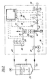
- FIG. 2 shows the functional diagram of a gas loading unit with a Polyurethane component K filled storage tank 20 in the slowly rotating Stirrer 21 ensure that contained in the polyurethane component Do not settle fillers.
- a Component inlet line 22 via a pump 23 with frequency-controlled motor to the mixer 24 according to the invention, which is shown in more detail in Fig. 3 and to this Figure will be explained in more detail below.
- the mixer 24 performs a return line 25 via a measuring unit 26 for measurement the gas loading level in the storage tank 20.
- the measured values of the measuring unit 26 are fed to a computer 27.
- a pressure measuring point 28 is arranged, of which the pressure readings of the mixer 24 converging component in the computer 27th be transmitted.
- the computer 27 the pressure readings from the Gas supply 29 fed.
- the mixer 24 consists of a cylindrical mixing container 38, in the direction of the axis of the Mixing container 38 reciprocable mixing elements 39 are arranged. Of the Drive motor for the reciprocating motion (not shown) is outside the Mixing tank 38. From the mixing tank 38 branches the component return line 25 off. At the bottom of the mixing tank 38, a closes in the Mixing container 38 opening pipe 40, in the opening 41, the mixing elements 39 are retractable and retractable. In the position of the movable Mixing elements 39 are arranged at a distance from the opening 41 and form a free passage for the polyurethane component from the pipe 40 in the Mixing container 38.
- the Mixing elements 39 are immersed in the tube 40, so that the polyurethane component must flow through the mixing elements.
- the flow resistance can be varied by the immersion depth of the mixing element 39.
- static mixing elements 42 are arranged.
- the axial movable mixing elements 39 and the static mixing elements 42 are only shown schematically. They can have identical structure and one correspond to commercial design, such as one in Fig. 4 in a perspective view is shown with different hired Leit- and Verwirbelungs vom.
- the Tube 40 is in the embodiment shown in Fig. 3 of a housing surround. In principle, however, the tube 40 can also be formed by the housing alone become.
- the component feed line 22 opens for the component K, as well as the gas nozzle 43 of the gas supply line 29. Im another is located in the region of the junction of the component K and the gas G is the ultrasonic sonotrode 36.
- an operating phase in which the polyurethane injection molding is started, can in a static mixer with fixed mixing elements from the storage tank 20 and the component feed line 22 supplied polyurethane component still do not have the required operating temperature.
- the start of the polyurethane injection molding plant in the cold state with such mixers is not possible because the pseudoplastic polyurethane component (isocyanate or polyol) is too viscous and the system would exceed the maximum allowable operating pressure.
- the movable Mixing elements 39 are set (representation in FIG. 3 in solid lines) that between the opening 41 and the mixing elements 39 a free passage for the Passage of the gas acted upon polyurethane component K + G consists.
- the System can therefore already in the start-up phase with that of the pump 23 generated maximum operating pressure (eg 25 bar) are operated.
- the movable mixing element 39 With increasing Heating of the polyurethane component, the movable mixing element 39 at brought the opening 41 and retracted further into the tube 40. This process is over that shown in Fig.
Landscapes
- Engineering & Computer Science (AREA)
- Mechanical Engineering (AREA)
- Processing And Handling Of Plastics And Other Materials For Molding In General (AREA)
- Polyurethanes Or Polyureas (AREA)
- Elimination Of Static Electricity (AREA)
- Casting Or Compression Moulding Of Plastics Or The Like (AREA)
- Accessories For Mixers (AREA)
- Fertilizers (AREA)
- Injection Moulding Of Plastics Or The Like (AREA)
Description
- Fig. 1 a:
- eine Ausführungsform eines Mischbehälters nach dem Stand der Technik,
- Fig. 1b:
- eine andere Ausführungsform eines Mischbehälters nach dem Stand der Technik,
- Fig. 2:
- ein Funktionsschema der erfindungsgemäßen Gasbeladungseinheit,
- Fig. 3:
- die Detaildarstellung des Mischbehälters nach Fig. 2 im vergrößerten Maßstab, mit statischen Mischelementen und Ultraschallsonotrode und
- Fig. 4:
- die Detailansicht eines in den Figuren 2 und 3 lediglich schematisch dargestellten Mischelements.
- 1
- Mischer
- 2
- Rührer
- 3
- Rührflügel
- 4
- Komponentenzuführleitung
- 5
- Gaszuführleitung
- 11
- Mischer
- 12
- Rührer
- 13
- Hohlwelle
- 14
- Gaskanal
- 15
- Rührflügel
- 16
- Komponentenzuführleitung
- 17
- Abführleitung
- 18
- Gasraum
- 20
- Bevorratungstank
- 21
- Rührer
- 22
- Komponentenzulaufleitung
- 23
- Pumpe
- 24
- Mischer
- 25
- Rückführleitung
- 26
- Messeinheit
- 27
- Rechner
- 28
- Druckmesspunkt
- 29
- Gaszuführleitung
- 30
- Steuerleitung (für Stellmotor der bewegl. Mischelemente)
- 31
- Mischelemente, beweglich
- 32
- Steuerleitung (für Gas- Auf/Zu-Stellelement)
- 33
- Auf/Zu-Stellelement
- 34
- Steuerleitung (für Pumpe 23)
- 35
- Steuerleitung (für Ultraschallsonotrode 36)
- 36
- Ultraschallsonotrode
- 37
- Einheit zur Messung vom Gasdruck und Gasdruckflussmenge
- 38
- Mischbehälter, zylindrisch
- 39
- Mischelemente
- 40
- Rohr
- 41
- Öffnung
- 42
- Mischelement, statisch
- 43
- Gasdüse
Claims (3)
- Gasbeladungseinheit für eine flüssige Polyurethan-Komponente, insbesondere eine mit Füllstoff beladene Polyurethan-Komponente einer Polyurethan-Spritzgießanlage, mit einem Mischbehälter, in dem bewegliche Mischelemente angeordnet sind und in dem die flüssige Polyurethan-Komponente mit über einer Düse zugeführtem Gas eingeleitet wird, dadurch gekennzeichnet, dass die beweglichen Mischelemente (39) im Mischbehälter (38) fluchtend und axial zu einer Öffnung (41) im Mischbehälter (38) verstellbar angeordnet sind, über die die Polyurethan-Komponente mit dem über eine Düse zugeführten Gas einleitbar ist.
- Gasbeladungseinheit nach Anspruch 1, dadurch gekennzeichnet, dass der Mischbehälter (38) zylindrisch und die Öffnung (41) das Ende eines in den Mischbehälters (38) mündenden Rohres (40) ist, in das die beweglichen Mischelemente (39) einführbar sind und an dessen anderem Ende die flüssige Polyurethan-Komponente (K) eingeleitet und das Gas (G) über eine Düse (43) injiziert wird, wobei die flüssige Polyurethan-Komponente (K) nach der Injektion das Gases durch ein oder mehrere feste Mischelemente 42 geleitet wird.
- Gasbeladungseinheit nach einem der Ansprüche 1 und 2, dadurch gekennzeichnet, dass in Bereich der Eindüsung des Gases (G) in die flüssige Polyurethan-Komponente (K) eine Ultraschallsonotrode (36) angeordnet ist.
Applications Claiming Priority (3)
| Application Number | Priority Date | Filing Date | Title |
|---|---|---|---|
| DE10157726A DE10157726A1 (de) | 2001-11-24 | 2001-11-24 | Gasbeladungseinheit einer Polyurethanspritzgießanlage |
| DE10157726 | 2001-11-24 | ||
| PCT/EP2002/012654 WO2003045653A1 (de) | 2001-11-24 | 2002-11-13 | Gasbeladungseinheit einer polyurethanspritzgiessanlage |
Publications (2)
| Publication Number | Publication Date |
|---|---|
| EP1461191A1 EP1461191A1 (de) | 2004-09-29 |
| EP1461191B1 true EP1461191B1 (de) | 2005-06-29 |
Family
ID=7706873
Family Applications (1)
| Application Number | Title | Priority Date | Filing Date |
|---|---|---|---|
| EP02779552A Expired - Lifetime EP1461191B1 (de) | 2001-11-24 | 2002-11-13 | Gasbeladungseinheit einer polyurethanspritzgiessanlage |
Country Status (8)
| Country | Link |
|---|---|
| US (1) | US6957805B2 (de) |
| EP (1) | EP1461191B1 (de) |
| CN (1) | CN1568247A (de) |
| AT (1) | ATE298653T1 (de) |
| AU (1) | AU2002342905A1 (de) |
| DE (2) | DE10157726A1 (de) |
| ES (1) | ES2242886T3 (de) |
| WO (1) | WO2003045653A1 (de) |
Families Citing this family (4)
| Publication number | Priority date | Publication date | Assignee | Title |
|---|---|---|---|---|
| US10232326B2 (en) | 2014-11-19 | 2019-03-19 | Simchem Inc. | Adhesive-air infuser device and method of using the same |
| DE102015120526B4 (de) | 2015-11-26 | 2017-07-13 | Webasto SE | Vorrichtung und Verfahren zur Aufbereitung eines flüssigen Polymergemisches |
| US10786801B2 (en) * | 2016-11-22 | 2020-09-29 | Khalifa University of Science and Technology | Continuous sono-chemical reactors and methods of using the same |
| CN112659449B (zh) * | 2020-12-03 | 2022-06-07 | 长虹美菱股份有限公司 | 一种转换型聚氨酯注料枪头 |
Family Cites Families (18)
| Publication number | Priority date | Publication date | Assignee | Title |
|---|---|---|---|---|
| DE1067207B (de) * | 1955-12-16 | 1959-10-15 | Farbenfabriken Bayer Aktiengesellschaft, Leverkusen-Bayerwerk | Vorrichtung zur Regulierung der Porenstruktur von Schaumstoffen auf Polyisocyanat-Basis |
| US3111389A (en) * | 1959-10-22 | 1963-11-19 | Chrysler Corp | Apparatus for preparing polyurethane foam compositions and the like |
| US3232709A (en) * | 1961-11-13 | 1966-02-01 | United Process Machinery Compa | Foam generating apparatus |
| FR1487774A (fr) * | 1963-07-03 | 1967-07-07 | Schaum Chemie W Bauer Kg Fa | Chambre de mélange pour la production en continu de mousse de résine synthétique |
| CH504942A (de) * | 1969-01-18 | 1971-03-31 | Pfeiffer Vakuumtechnik | Anlage zur Giessharzverarbeitung |
| US3604509A (en) * | 1969-05-15 | 1971-09-14 | Norman H Sachnik | Airplane foam generator |
| DE2746188A1 (de) * | 1977-10-14 | 1979-04-19 | Bayer Ag | Verfahren und vorrichtung zum mischen und auftragen reaktionsfaehiger stoffe |
| DE3226412A1 (de) * | 1982-07-15 | 1984-01-19 | Maschinenfabrik Hennecke Gmbh, 5090 Leverkusen | Verfahren und mischkopf zum herstellen eines reaktionsgemisches aus mindestens zwei fliessfaehigen reaktionskomponenten |
| JPS6097805A (ja) * | 1983-11-02 | 1985-05-31 | Kobe Steel Ltd | 単軸混練押出機 |
| EP0191453A3 (de) * | 1985-02-14 | 1989-01-04 | Siemens Aktiengesellschaft | Einrichtung zur Verhinderung von Anlagerungen in Strömungsräumen für Reaktionsharze |
| CA1255866A (en) * | 1985-07-24 | 1989-06-20 | Hiromu Fujisaki | Method and apparatus for production of foamed thermoplastic material |
| US5255747A (en) * | 1992-10-01 | 1993-10-26 | Hale Fire Pump Company | Compressed air foam system |
| DE4420168C1 (de) * | 1994-06-09 | 1996-02-08 | Hennecke Gmbh Maschf | Verfahren zur Steuerung der Zellenzahl in Polyurethan-Schaumstoffen |
| RU2077421C1 (ru) * | 1994-10-06 | 1997-04-20 | Коммерческая внедренческо-научная фирма "Приват-Деал" | Устройство для аэрации строительного раствора |
| DE4446876A1 (de) * | 1994-12-27 | 1996-07-04 | Bayer Ag | Verfahren und Vorrichtung zur Schaumherstellung mittels unter Druck gelöstem Kohlendioxid |
| US5874031A (en) * | 1995-12-01 | 1999-02-23 | Sunstar Engineering Inc. | Method of and apparatus for foaming a viscous material |
| US6538040B1 (en) * | 1995-12-01 | 2003-03-25 | Sunstar Giken Kabushiki Kaisha | Method and apparatus for mixing a high-viscosity material into a gas |
| US6602916B2 (en) * | 2001-08-17 | 2003-08-05 | Halliburton Energy Services, Inc | Foaming apparatus and method |
-
2001
- 2001-11-24 DE DE10157726A patent/DE10157726A1/de not_active Withdrawn
-
2002
- 2002-11-13 AT AT02779552T patent/ATE298653T1/de not_active IP Right Cessation
- 2002-11-13 AU AU2002342905A patent/AU2002342905A1/en not_active Abandoned
- 2002-11-13 ES ES02779552T patent/ES2242886T3/es not_active Expired - Lifetime
- 2002-11-13 WO PCT/EP2002/012654 patent/WO2003045653A1/de not_active Ceased
- 2002-11-13 CN CNA028203534A patent/CN1568247A/zh active Pending
- 2002-11-13 DE DE50203535T patent/DE50203535D1/de not_active Expired - Fee Related
- 2002-11-13 EP EP02779552A patent/EP1461191B1/de not_active Expired - Lifetime
-
2004
- 2004-05-14 US US10/846,328 patent/US6957805B2/en not_active Expired - Fee Related
Also Published As
| Publication number | Publication date |
|---|---|
| ATE298653T1 (de) | 2005-07-15 |
| DE10157726A1 (de) | 2003-06-05 |
| CN1568247A (zh) | 2005-01-19 |
| WO2003045653A1 (de) | 2003-06-05 |
| AU2002342905A1 (en) | 2003-06-10 |
| US6957805B2 (en) | 2005-10-25 |
| EP1461191A1 (de) | 2004-09-29 |
| ES2242886T3 (es) | 2005-11-16 |
| DE50203535D1 (de) | 2005-08-04 |
| US20040207101A1 (en) | 2004-10-21 |
Similar Documents
| Publication | Publication Date | Title |
|---|---|---|
| EP0229328B1 (de) | Doppelwellen-Zwangsmischer für kontinuierliche und diskontinuierliche Arbeitsweise | |
| EP2720783B1 (de) | Anlage zur dispersion von feindispersen feststoffen in hochviskosen produkten | |
| EP0729780B1 (de) | Anlage zum Mischen von Flüssigkeit und Feststoff | |
| DE4024994C2 (de) | Vorrichtung zum Beschicken von Spritzgieß- und Extrudereinheiten | |
| DE2649996A1 (de) | Verfahren und vorrichtung zum herstellen eines fuellstoffhaltigen reaktionsgemisches aus mindestens zwei fliessfaehigen komponenten, insbesondere zum erzeugen von polyurethan | |
| DE102010028774A1 (de) | Emulgiereinrichtung zur kontinuierlichen Herstellung von Emulsionen und/oder Dispersionen | |
| CH628458A5 (de) | Verfahren zum einbinden fluessigkeitshaltiger radioaktiver abfallstoffe und knetvorrichtung dafuer. | |
| DE3537729C2 (de) | Vorrichtung zum Mischen und Pumpen einer spritzfähigen, feuerfesten Aufschlämmung | |
| DE102014117734A1 (de) | Vorrichtung und Verfahren zum Beladen einer Flüssigkeit mit einem Gas | |
| DE1244723B (de) | Vorrichtung zum kontinuierlichen Mischen von trockenem Gut mit einer Fluessigkeit | |
| EP1273341B1 (de) | Vorrichtung zum vertikalen Mischen | |
| DE10018856C1 (de) | Vorrichtung zum Befüllen und Entgasen eines Vorratsbehälters für viskose Produkte, Container zum Nachfüllen dieser Vorrichtung und Verfahren zum Betrieb | |
| DE4028064A1 (de) | Verfahren und vorrichtung zum mischen von mischgut mit thermoplastischem kunststoff | |
| DE2805942C2 (de) | Vorrichtung zum Homogenisieren fließfähiger Stoffe | |
| EP1461191A1 (de) | Gasbeladungseinheit einer polyurethanspritzgiessanlage | |
| DE212013000285U1 (de) | Durchlaufmischer | |
| EP0684115B1 (de) | Verfahren zur Herstellung eines füllstoffhaltigen Reaktionsgemisches | |
| CH429666A (de) | Kontinuierliches Mischverfahren, insbesondere zur Herstellung von Mischungen aus pulvrigen bis körnigen Feststoffen mit flüssigen oder thermoplastischen Bindemitteln | |
| EP0236883B1 (de) | Vorrichtung zum Erzeugen einer Entgiftungsemulsion für Kampfstoffe | |
| EP0332032B1 (de) | Verfahren und Vorrichtung zum Beladen mindestens einer fliessfähigen Reaktionskomponente mit Gas, insbesondere in geringen Mengen, für die Herstellung von Schaumstoffen, insbesondere Polyurethanschaumstoffen | |
| DE19848060C2 (de) | Dosier- und Fördereinrichtung für Kunststoffkomponenten | |
| EP0714596A1 (de) | Fütterungseinrichtung für Viehfuttermischungen | |
| DE2701508A1 (de) | Verfahren zur kontinuierlichen herstellung und foerderung einer mischung aus fein- bis grobkoernigem material mit einer fluessigkeit und vorrichtung zur durchfuehrung des verfahrens | |
| DE2323196A1 (de) | Vorrichtung zum lagern, transportieren und kontinuierlichen anmischen und verspritzen von trockenmoertel | |
| DE19643038B4 (de) | Vorrichtung und Verfahren zum Pumpen von Dickstoffgemischen |
Legal Events
| Date | Code | Title | Description |
|---|---|---|---|
| PUAI | Public reference made under article 153(3) epc to a published international application that has entered the european phase |
Free format text: ORIGINAL CODE: 0009012 |
|
| 17P | Request for examination filed |
Effective date: 20040624 |
|
| AK | Designated contracting states |
Kind code of ref document: A1 Designated state(s): AT BE BG CH CY CZ DE DK EE ES FI FR GB GR IE IT LI LU MC NL PT SE SK TR |
|
| AX | Request for extension of the european patent |
Extension state: AL LT LV MK RO SI |
|
| GRAP | Despatch of communication of intention to grant a patent |
Free format text: ORIGINAL CODE: EPIDOSNIGR1 |
|
| GRAS | Grant fee paid |
Free format text: ORIGINAL CODE: EPIDOSNIGR3 |
|
| GRAA | (expected) grant |
Free format text: ORIGINAL CODE: 0009210 |
|
| AK | Designated contracting states |
Kind code of ref document: B1 Designated state(s): AT BE BG CH CY CZ DE DK EE ES FI FR GB GR IE IT LI LU MC NL PT SE SK TR |
|
| PG25 | Lapsed in a contracting state [announced via postgrant information from national office to epo] |
Ref country code: FI Free format text: LAPSE BECAUSE OF FAILURE TO SUBMIT A TRANSLATION OF THE DESCRIPTION OR TO PAY THE FEE WITHIN THE PRESCRIBED TIME-LIMIT Effective date: 20050629 Ref country code: NL Free format text: LAPSE BECAUSE OF FAILURE TO SUBMIT A TRANSLATION OF THE DESCRIPTION OR TO PAY THE FEE WITHIN THE PRESCRIBED TIME-LIMIT Effective date: 20050629 Ref country code: IE Free format text: LAPSE BECAUSE OF FAILURE TO SUBMIT A TRANSLATION OF THE DESCRIPTION OR TO PAY THE FEE WITHIN THE PRESCRIBED TIME-LIMIT Effective date: 20050629 Ref country code: EE Free format text: LAPSE BECAUSE OF FAILURE TO SUBMIT A TRANSLATION OF THE DESCRIPTION OR TO PAY THE FEE WITHIN THE PRESCRIBED TIME-LIMIT Effective date: 20050629 Ref country code: TR Free format text: LAPSE BECAUSE OF FAILURE TO SUBMIT A TRANSLATION OF THE DESCRIPTION OR TO PAY THE FEE WITHIN THE PRESCRIBED TIME-LIMIT Effective date: 20050629 Ref country code: SK Free format text: LAPSE BECAUSE OF FAILURE TO SUBMIT A TRANSLATION OF THE DESCRIPTION OR TO PAY THE FEE WITHIN THE PRESCRIBED TIME-LIMIT Effective date: 20050629 |
|
| REG | Reference to a national code |
Ref country code: GB Ref legal event code: FG4D Free format text: NOT ENGLISH |
|
| REG | Reference to a national code |
Ref country code: CH Ref legal event code: EP |
|
| GBT | Gb: translation of ep patent filed (gb section 77(6)(a)/1977) |
Effective date: 20050629 |
|
| REF | Corresponds to: |
Ref document number: 50203535 Country of ref document: DE Date of ref document: 20050804 Kind code of ref document: P |
|
| REG | Reference to a national code |
Ref country code: IE Ref legal event code: FG4D Free format text: LANGUAGE OF EP DOCUMENT: GERMAN |
|
| PG25 | Lapsed in a contracting state [announced via postgrant information from national office to epo] |
Ref country code: DK Free format text: LAPSE BECAUSE OF FAILURE TO SUBMIT A TRANSLATION OF THE DESCRIPTION OR TO PAY THE FEE WITHIN THE PRESCRIBED TIME-LIMIT Effective date: 20050929 Ref country code: GR Free format text: LAPSE BECAUSE OF FAILURE TO SUBMIT A TRANSLATION OF THE DESCRIPTION OR TO PAY THE FEE WITHIN THE PRESCRIBED TIME-LIMIT Effective date: 20050929 Ref country code: SE Free format text: LAPSE BECAUSE OF FAILURE TO SUBMIT A TRANSLATION OF THE DESCRIPTION OR TO PAY THE FEE WITHIN THE PRESCRIBED TIME-LIMIT Effective date: 20050929 Ref country code: BG Free format text: LAPSE BECAUSE OF FAILURE TO SUBMIT A TRANSLATION OF THE DESCRIPTION OR TO PAY THE FEE WITHIN THE PRESCRIBED TIME-LIMIT Effective date: 20050929 |
|
| PG25 | Lapsed in a contracting state [announced via postgrant information from national office to epo] |
Ref country code: CY Free format text: LAPSE BECAUSE OF FAILURE TO SUBMIT A TRANSLATION OF THE DESCRIPTION OR TO PAY THE FEE WITHIN THE PRESCRIBED TIME-LIMIT Effective date: 20051113 Ref country code: AT Free format text: LAPSE BECAUSE OF NON-PAYMENT OF DUE FEES Effective date: 20051113 |
|
| REG | Reference to a national code |
Ref country code: ES Ref legal event code: FG2A Ref document number: 2242886 Country of ref document: ES Kind code of ref document: T3 |
|
| PG25 | Lapsed in a contracting state [announced via postgrant information from national office to epo] |
Ref country code: MC Free format text: LAPSE BECAUSE OF NON-PAYMENT OF DUE FEES Effective date: 20051130 Ref country code: BE Free format text: LAPSE BECAUSE OF NON-PAYMENT OF DUE FEES Effective date: 20051130 Ref country code: LU Free format text: LAPSE BECAUSE OF NON-PAYMENT OF DUE FEES Effective date: 20051130 |
|
| NLV1 | Nl: lapsed or annulled due to failure to fulfill the requirements of art. 29p and 29m of the patents act | ||
| PG25 | Lapsed in a contracting state [announced via postgrant information from national office to epo] |
Ref country code: PT Free format text: LAPSE BECAUSE OF FAILURE TO SUBMIT A TRANSLATION OF THE DESCRIPTION OR TO PAY THE FEE WITHIN THE PRESCRIBED TIME-LIMIT Effective date: 20051207 |
|
| REG | Reference to a national code |
Ref country code: IE Ref legal event code: FD4D |
|
| ET | Fr: translation filed | ||
| PLBE | No opposition filed within time limit |
Free format text: ORIGINAL CODE: 0009261 |
|
| STAA | Information on the status of an ep patent application or granted ep patent |
Free format text: STATUS: NO OPPOSITION FILED WITHIN TIME LIMIT |
|
| 26N | No opposition filed |
Effective date: 20060330 |
|
| PGFP | Annual fee paid to national office [announced via postgrant information from national office to epo] |
Ref country code: CZ Payment date: 20061106 Year of fee payment: 5 |
|
| PGFP | Annual fee paid to national office [announced via postgrant information from national office to epo] |
Ref country code: FR Payment date: 20061124 Year of fee payment: 5 |
|
| PGFP | Annual fee paid to national office [announced via postgrant information from national office to epo] |
Ref country code: GB Payment date: 20061127 Year of fee payment: 5 |
|
| PGFP | Annual fee paid to national office [announced via postgrant information from national office to epo] |
Ref country code: ES Payment date: 20061129 Year of fee payment: 5 |
|
| PG25 | Lapsed in a contracting state [announced via postgrant information from national office to epo] |
Ref country code: LI Free format text: LAPSE BECAUSE OF NON-PAYMENT OF DUE FEES Effective date: 20061130 Ref country code: CH Free format text: LAPSE BECAUSE OF NON-PAYMENT OF DUE FEES Effective date: 20061130 |
|
| PGFP | Annual fee paid to national office [announced via postgrant information from national office to epo] |
Ref country code: IT Payment date: 20061130 Year of fee payment: 5 |
|
| REG | Reference to a national code |
Ref country code: CH Ref legal event code: PL |
|
| BERE | Be: lapsed |
Owner name: KRAUSS-MAFFEI KUNSTSTOFFTECHNIK G.M.B.H. Effective date: 20051130 |
|
| GBPC | Gb: european patent ceased through non-payment of renewal fee |
Effective date: 20071113 |
|
| PG25 | Lapsed in a contracting state [announced via postgrant information from national office to epo] |
Ref country code: CZ Free format text: LAPSE BECAUSE OF NON-PAYMENT OF DUE FEES Effective date: 20071113 |
|
| REG | Reference to a national code |
Ref country code: FR Ref legal event code: ST Effective date: 20080930 |
|
| PG25 | Lapsed in a contracting state [announced via postgrant information from national office to epo] |
Ref country code: GB Free format text: LAPSE BECAUSE OF NON-PAYMENT OF DUE FEES Effective date: 20071113 |
|
| PGFP | Annual fee paid to national office [announced via postgrant information from national office to epo] |
Ref country code: DE Payment date: 20081121 Year of fee payment: 7 |
|
| REG | Reference to a national code |
Ref country code: ES Ref legal event code: FD2A Effective date: 20071114 |
|
| PG25 | Lapsed in a contracting state [announced via postgrant information from national office to epo] |
Ref country code: FR Free format text: LAPSE BECAUSE OF NON-PAYMENT OF DUE FEES Effective date: 20071130 Ref country code: ES Free format text: LAPSE BECAUSE OF NON-PAYMENT OF DUE FEES Effective date: 20071114 |
|
| PG25 | Lapsed in a contracting state [announced via postgrant information from national office to epo] |
Ref country code: IT Free format text: LAPSE BECAUSE OF NON-PAYMENT OF DUE FEES Effective date: 20071113 |
|
| PG25 | Lapsed in a contracting state [announced via postgrant information from national office to epo] |
Ref country code: DE Free format text: LAPSE BECAUSE OF NON-PAYMENT OF DUE FEES Effective date: 20100601 |