EP1460686A2 - Method for Thin Film Resistor Integration in Dual Damascene Structure - Google Patents
Method for Thin Film Resistor Integration in Dual Damascene Structure Download PDFInfo
- Publication number
- EP1460686A2 EP1460686A2 EP04101105A EP04101105A EP1460686A2 EP 1460686 A2 EP1460686 A2 EP 1460686A2 EP 04101105 A EP04101105 A EP 04101105A EP 04101105 A EP04101105 A EP 04101105A EP 1460686 A2 EP1460686 A2 EP 1460686A2
- Authority
- EP
- European Patent Office
- Prior art keywords
- thin film
- film resistor
- dielectric layer
- trench
- forming
- Prior art date
- Legal status (The legal status is an assumption and is not a legal conclusion. Google has not performed a legal analysis and makes no representation as to the accuracy of the status listed.)
- Ceased
Links
Images


Classifications
-
- H—ELECTRICITY
- H10—SEMICONDUCTOR DEVICES; ELECTRIC SOLID-STATE DEVICES NOT OTHERWISE PROVIDED FOR
- H10D—INORGANIC ELECTRIC SEMICONDUCTOR DEVICES
- H10D1/00—Resistors, capacitors or inductors
- H10D1/40—Resistors
- H10D1/47—Resistors having no potential barriers
-
- H—ELECTRICITY
- H10—SEMICONDUCTOR DEVICES; ELECTRIC SOLID-STATE DEVICES NOT OTHERWISE PROVIDED FOR
- H10W—GENERIC PACKAGES, INTERCONNECTIONS, CONNECTORS OR OTHER CONSTRUCTIONAL DETAILS OF DEVICES COVERED BY CLASS H10
- H10W20/00—Interconnections in chips, wafers or substrates
- H10W20/01—Manufacture or treatment
-
- H—ELECTRICITY
- H10—SEMICONDUCTOR DEVICES; ELECTRIC SOLID-STATE DEVICES NOT OTHERWISE PROVIDED FOR
- H10W—GENERIC PACKAGES, INTERCONNECTIONS, CONNECTORS OR OTHER CONSTRUCTIONAL DETAILS OF DEVICES COVERED BY CLASS H10
- H10W20/00—Interconnections in chips, wafers or substrates
- H10W20/40—Interconnections external to wafers or substrates, e.g. back-end-of-line [BEOL] metallisations or vias connecting to gate electrodes
- H10W20/498—Resistive arrangements or effects of, or between, wiring layers
Definitions
- the invention is generally related to the field of thin film resistors and more specifically to a method of forming a thin film resistor in a dual damascene structure with copper interconnects.
- Thin film resistors are very attractive components for high precision analog and mixed signal applications. In addition to a low thermal coefficient of resistance, low voltage coefficient of resistance, and good resistor matching they should provide good stability under stress.
- Integrated circuit copper interconnects are formed using damascene processes.
- a damascene process a trench is first formed in a dielectric layer.
- the trench is then filled with copper and the excess copper is removed by a number of methods including chemical mechanical polishing.
- the formation of thin film resistors in an integrated cir cuit containing copper interconnects presents many challenges.
- the thin film resistor is not formed using copper and so is incompatible with existing damascene processes.
- the incompatibility is exacerbated by the requirement that the thin film resistors be formed in the same levels as the copper interconnects. There is therefore a need for a method to form thin film resistors in integrated circuits with copper interconnects formed using damascene processes.
- the instant invention describes a method for integrating a thin film resistor into an integrated circuit comprising copper interconnects formed using dual damascene structures.
- an etch stop layer is formed on a dielectric layer.
- a thin film resistor is formed over the etch stop layer and contact pads are formed on the thin film resistor.
- a second dielectric layer is formed over the thin film resistor and at least one trench is formed in the second dielectric layer.
- thin film resistor vias are formed above the contact pads on the thin film resistor.
- a via trench is formed in the trench structure and metal is formed in the trench, via trench, and thin film resistor vias.
- FIG. 1 (a) An embodiment of the instant invention is shown in Figure 1 (a) - Figure 1 (f) .
- a metal interconnect 20 is formed over a dielectric layer 10.
- the dielectric layer 10 is formed over a semiconductor substrate and any number of intervening layers.
- the semiconductor and any intervening layers have been omitted from the Figures for clarity.
- the layers beneath the dielectric layer 10 will comprise any number of active devices including MOS and/or bipolar transistors as well as any number of metal interconnect levels.
- an inter-level dielectric layer 30 is formed over the metal interconnect layer 20.
- the inter -level dielectric layer 30 can comprise silicon oxide formed using any suitable method including chemical vapor deposition.
- the inter-level dielectric layer 30 is formed using material selected from the group comprising TEOS silicon oxides, PECVD silicon oxides, silicon nitrides, silicon oxynitrides, silicon carbides, spin-on glass (SOG) such as silsesquioxanes and siloxane, xerogels or any other suitable material.
- SOG spin-on glass
- an etch stop layer 40 is formed over the inter-level dielectric layer 30.
- the etch stop layer 40 can comprise silicon nitride, silicon carbide, silicon oxynitride, combinations of one or all of these and other suitable layers, and any other suitable dielectric material.
- a thin film resistor layer 50 is then formed over the etch stop layer 40. In subsequent processing the resistor layer 50 will be etched to form the thin film resistor (TFR).
- the resistor layer 50 is formed using a silicon chromium (SiCr) alloy, nickel chromium (NiCr) alloy, tantalum nitride, titanium nitride, tungsten, or any other suitable material.
- a photoresist layer 58 is formed and patterned over the thin film resistor layer 50 and will be used to define the TFR during the etching process.
- FIG. 1 (b) Shown in Figure 1 (b) is the TFR 55 formed by etching the resistor layer 50 using the photoresist layer 58 shown in Figure 1(a) as a masking layer.
- the resistor layer 50 can be etched using any suitable dry or wet etching process.
- a conductive contact layer 60 is formed over the TFR structure 55.
- the conductive contact layer 60 is formed using titanium nitride, titanium tungsten, or any other suitable conductive material.
- the conductive contact layer 60 can comprise multiple layers formed using layers comprised of the same or differing conductive material.
- patterned photoresist 70 is formed over the capping layer as shown in Figure 1 (b) and will be used to pattern the contact layer 60.
- inter-level dielectric layer 80 is formed over the TFR 55.
- the inter-level dielectric layer 80 can comprise silicon oxide formed using any suitable method including chemical vapor deposition.
- the inter-level dielectric layer 80 is formed using material selected from the group comprising TEOS silicon oxides, PECVD silicon oxides, silicon nitrides, silicon oxynitrides, silicon carbides, spin-on glass (SOG) such as silsesquioxanes and siloxane, xerogels or any other suitable material.
- patterned photoresist layers 90 are formed on the inter-level dielectric layer 80.
- the patterned photoresist layers 90 will function as etch masks during the subsequent etching of vias and trenches in the dielectric layer 80.
- FIG. 1(d) Shown in Figure 1(d) is the structure of Figure 1(c) following the simultaneous etching of TFR vias 92 and a trench 94 in the inter-level dielectric layer 80.
- TFR and trench are shown in the Figure, it should be noted that the method of the instant invention could be used to form any number of trench and via structures in the dielectric layer in addition to the TFR vias.
- a via will be used in the instant invention to describe a structure that contacts an underlying conductive layer such as a TFR, a metal interconnect, or an electronic device.
- a trench will be used to describe the structure formed in the dielectric lay er in which a metal interconnect line will be formed.
- the etching of the inter -level dielectric layer 80 in Figure 1 (d) is performed using a dry etch process that is designed to stop on the etch stop layer 40.
- a dry etch process that is designed to stop on the etch stop layer 40.
- any dry etch process with high silicon oxide to silicon nitride selectivity can be used.
- the contact pads 65 will protect the regions of the TFR 55 that would have been exposed to the etch process.
- the etch process used should therefore also have high selectivity between the dielectric layer 80 and the contact pads 65.
- the etched TFR vias 92 will be used to provide electrical contact to the TFR 55 and a copper interconnect metal line will be formed in the trench structure 94.
- a patterned photoresist layer 100 is formed and used as a mask during the formation of t he trench via 96.
- the trench via 96 is formed by etching through the etch stop layer 40 and the underlying dielectric layer 30.
- the photoresist layer 100 is removed and metal 120 and 11 0 is formed in the TFR vias and the trench and trench via respectively.
- the metal formed can comprise copper or any other suitable metal.
- 120 and 110 can be formed using any known integrated circuit processing method including copper metal deposition and chemical mechanical polishing.
- the integrated circuit can be completed using known manufacturing methods.
- FIG. 2(a)- Figure 2(d) A further embodiment of the instant invention is shown in Figure 2(a)- Figure 2(d). Shown in Figure 2(a) is a metal interconnect 20 is formed over a dielectric layer 10. An inter-level dielectric layer 30 is formed on the metal interconnect layer 10.
- the inter-level dielectric layer 30 can comprise silicon oxide formed using any suitable method including chemical vapor deposition.
- the inter-level dielectric layer 30 is formed using material selected from the group comprising TEOS silicon oxides, PECVD silicon oxides, silicon nitrides, silicon oxynitrides, silicon carbides, spin -on glass (SOG) such as silsesquioxanes and siloxane, xerogels or any other suitable material.
- SOG spin -on glass
- the resistor layer is formed using a silicon chromium (SiCr) alloy, nickel chromium (NiCr) alloy, tantalum nitride, titanium nitride, tungsten, or any other suitable material.
- an inter-level dielectric layer 80 is formed over the TFR 55.
- the inter-level dielectric layer 80 can comprise silicon oxide formed using any suitable method including chemical vapor deposition.
- the inter-level dielectric layer 80 is formed using material selected from the group comprising TEOS silicon oxides, PECVD silicon oxides, silicon nitrides, silicon oxynitrides, silicon carbides, spin-on glass (SOG) such as silsesquioxanes and siloxane, xerogels or any other suitable material.
- patterned photoresist layers 90 are formed on the dielectric layer 80. The patterned photoresist layers 90 will function as etch masks during the subsequent etching of trenches in the dielectric layer 80.
- FIG. 2(b) Shown in Figure 2(b) is the structure of Figure 2(a) following the simultaneous etching of TFR vias 92 and the trench 94 in the dielectric layer 80.
- the etching of the inte r-level dielectric layer 80 in Figure 2(b) is performed using a timed dry etch process that is designed to stop upon etching through the dielectric layer 80. It is not critical that the etch process stop immediately at the interface between the dielectric layers 80 and 30. It is however important that the contact pads 65 be exposed following the etch process. During the etching of the inter -level dielectric layer 80, the contact pads 65 will protect the regions of the TFR 55 that would have been exposed to the etch process. This implies that the etch process used should also have high selectivity between the dielectric layer 80 and the contact pads 65.
- the etched TFR vias 92 will be used to provide electrical contact to the TFR 55 and a copper interconnect will be formed in the trench structure 94.
- a patterned photoresist layer 100 is formed and used as a mask during the formation of the trench via 96.
- the trench via 96 is formed by etching through the etch stop layer 40 and the underlying inter-level dielectric layer 30.
- the photoresist layer 100 is removed and copper metal 120 and 110 is formed in the TFR vias, the trench, and the trench via.
- the copper metal 120 and 110 can be formed using any known integrated circuit processing method including copper metal deposition and chemical mechanical polishing. Following the formation of the structure shown in Figure 2(d), the integrated circuit can be completed using known manufacturing methods.
Landscapes
- Internal Circuitry In Semiconductor Integrated Circuit Devices (AREA)
- Semiconductor Integrated Circuits (AREA)
Abstract
Description
- The invention is generally related to the field of thin film resistors and more specifically to a method of forming a thin film resistor in a dual damascene structure with copper interconnects.
- Thin film resistors are very attractive components for high precision analog and mixed signal applications. In addition to a low thermal coefficient of resistance, low voltage coefficient of resistance, and good resistor matching they should provide good stability under stress.
- High frequency mixed signal applications require the use of copper interconnects. Integrated circuit copper interconnects are formed using damascene processes. In a damascene process a trench is first formed in a dielectric layer. The trench is then filled with copper and the excess copper is removed by a number of methods including chemical mechanical polishing.
The formation of thin film resistors in an integrated cir cuit containing copper interconnects presents many challenges. The thin film resistor is not formed using copper and so is incompatible with existing damascene processes. The incompatibility is exacerbated by the requirement that the thin film resistors be formed in the same levels as the copper interconnects. There is therefore a need for a method to form thin film resistors in integrated circuits with copper interconnects formed using damascene processes. - The instant invention describes a method for integrating a thin film resistor into an integrated circuit comprising copper interconnects formed using dual damascene structures. In an embodiment of the instant invention an etch stop layer is formed on a dielectric layer. A thin film resistor is formed over the etch stop layer and contact pads are formed on the thin film resistor. A second dielectric layer is formed over the thin film resistor and at least one trench is formed in the second dielectric layer. At the same time thin film resistor vias are formed above the contact pads on the thin film resistor. A via trench is formed in the trench structure and metal is formed in the trench, via trench, and thin film resistor vias.
- In the drawings:
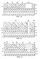
- Figure 1(a) to Figure 1(f) are cross-section drawings illustrating an embodiment of the instant invention.
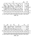
- Figure 2(a) to Figure 2(d) are cross -sectional drawings illustrating a further embodiment of the instant invention.
- Common reference numerals are used throughout the figures to represent like or similar features. The figures are not drawn to scale and are merely provided for illustrative purposes.
- While the following description of the instant invention revolves around Figures 1-2, the instant invention can be utilized in many semiconductor device structures. The methodology of the instant invention provides a solution to forming thin film resistors in integrated circuits comprising copper interconnects.
- An embodiment of the instant invention is shown in Figure 1 (a) -Figure 1 (f) . As shown in Figure 1 (a) a
metal interconnect 20 is formed over adielectric layer 10. Thedielectric layer 10 is formed over a semiconductor substrate and any number of intervening layers. The semiconductor and any intervening layers have been omitted from the Figures for clarity. Although omitted from the Figures, the layers beneath thedielectric layer 10 will comprise any number of active devices including MOS and/or bipolar transistors as well as any number of metal interconnect levels. As shown in Figure 1 (a) an inter-leveldielectric layer 30 is formed over themetal interconnect layer 20. The inter -leveldielectric layer 30 can comprise silicon oxide formed using any suitable method including chemical vapor deposition. In a first embodiment the inter-leveldielectric layer 30 is formed using material selected from the group comprising TEOS silicon oxides, PECVD silicon oxides, silicon nitrides, silicon oxynitrides, silicon carbides, spin-on glass (SOG) such as silsesquioxanes and siloxane, xerogels or any other suitable material. Following the formation of the inter-leveldielectric layer 30, anetch stop layer 40 is formed over the inter-leveldielectric layer 30. In an embodime nt theetch stop layer 40 can comprise silicon nitride, silicon carbide, silicon oxynitride, combinations of one or all of these and other suitable layers, and any other suitable dielectric material. A thinfilm resistor layer 50 is then formed over theetch stop layer 40. In subsequent processing theresistor layer 50 will be etched to form the thin film resistor (TFR). In an embodiment of the instant invention theresistor layer 50 is formed using a silicon chromium (SiCr) alloy, nickel chromium (NiCr) alloy, tantalum nitride, titanium nitride, tungsten, or any other suitable material. Aphotoresist layer 58 is formed and patterned over the thinfilm resistor layer 50 and will be used to define the TFR during the etching process. - Shown in Figure 1 (b) is the
TFR 55 formed by etching theresistor layer 50 using thephotoresist layer 58 shown in Figure 1(a) as a masking layer. Theresistor layer 50 can be etched using any suitable dry or wet etching process. Following the formation of the TFR structure 55 aconductive contact layer 60 is formed over theTFR structure 55. In an embodiment theconductive contact layer 60 is formed using titanium nitride, titanium tungsten, or any other suitable conductive material. In further embodiments of the instant invention theconductive contact layer 60 can comprise multiple layers formed using layers comprised of the same or differing conductive material. Following the formation of thecontact layer 60, patternedphotoresist 70 is formed over the capping layer as shown in Figure 1 (b) and will be used to pattern thecontact layer 60. - Following the etching of the
contact layer 60 shown in Figure 1(b),contact pads 65 are formed as shown in Figure 1(c). Thecontact pads 65 will protect the TFR 55 during the subsequent trench etch etch. Following the formation of thecontact pads 65, an inter-leveldielectric layer 80 is formed over theTFR 55. The inter-leveldielectric layer 80 can comprise silicon oxide formed using any suitable method including chemical vapor deposition. In an embodiment the inter-leveldielectric layer 80 is formed using material selected from the group comprising TEOS silicon oxides, PECVD silicon oxides, silicon nitrides, silicon oxynitrides, silicon carbides, spin-on glass (SOG) such as silsesquioxanes and siloxane, xerogels or any other suitable material. Following the formation of the inter-leveldielectric layer 80, patternedphotoresist layers 90 are formed on the inter-leveldielectric layer 80. The patternedphotoresist layers 90 will function as etch masks during the subsequent etching of vias and trenches in thedielectric layer 80. - Shown in Figure 1(d) is the structure of Figure 1(c) following the simultaneous etching of
TFR vias 92 and atrench 94 in the inter-leveldielectric layer 80. Although only a single TFR and trench is shown in the Figure, it should be noted that the method of the instant invention could be used to form any number of trench and via structures in the dielectric layer in addition to the TFR vias. It should also be noted that a via will be used in the instant invention to describe a structure that contacts an underlying conductive layer such as a TFR, a metal interconnect, or an electronic device. A trench will be used to describe the structure formed in the dielectric lay er in which a metal interconnect line will be formed. The etching of the inter -leveldielectric layer 80 in Figure 1 (d) is performed using a dry etch process that is designed to stop on theetch stop layer 40. In the case of a silicon oxidedielectric laye r 80 and a silicon nitrideetch stop layer 40, any dry etch process with high silicon oxide to silicon nitride selectivity can be used. It should be noted that during the etching of thedielectric layer 80, thecontact pads 65 will protect the regions of theTFR 55 that would have been exposed to the etch process. The etch process used should therefore also have high selectivity between thedielectric layer 80 and thecontact pads 65. Theetched TFR vias 92 will be used to provide electrical contact to the TFR 55 and a copper interconnect metal line will be formed in thetrench structure 94. - Following the formation of the
trench 94 and TFR vias 92 shown in Figure 1(d), a patternedphotoresist layer 100 is formed and used as a mask during the formation of t he trench via 96. The trench via 96 is formed by etching through theetch stop layer 40 and theunderlying dielectric layer 30. As shown in Figure 1 (f) , following the formation of the trench via 96, thephotoresist layer 100 is removed andmetal 120 and 11 0 is formed in the TFR vias and the trench and trench via respectively. In an embodiment of the instant invention the metal formed can comprise copper or any other suitable metal. For copper metal, 120 and 110 can be formed using any known integrated circuit processing method including copper metal deposition and chemical mechanical polishing. Following the formation of the structure shown in Figure 1 (f), the integrated circuit can be completed using known manufacturing methods. - A further embodiment of the instant invention is shown in Figure 2(a)-Figure 2(d). Shown in Figure 2(a) is a
metal interconnect 20 is formed over adielectric layer 10. An inter-leveldielectric layer 30 is formed on themetal interconnect layer 10. The inter-leveldielectric layer 30 can comprise silicon oxide formed using any suitable method including chemical vapor deposition. In a first embodiment the inter-leveldielectric layer 30 is formed using material selected from the group comprising TEOS silicon oxides, PECVD silicon oxides, silicon nitrides, silicon oxynitrides, silicon carbides, spin -on glass (SOG) such as silsesquioxanes and siloxane, xerogels or any other suitable material. Following the formation of the inter -level dielectric layer 30, athin film resistor 55 andcontact pads 65 are formed as described above. In an embodiment of the instant invention the resistor layer is formed using a silicon chromium (SiCr) alloy, nickel chromium (NiCr) alloy, tantalum nitride, titanium nitride, tungsten, or any other suitable material. - Following the formation of the
TFR 55 and thecontact pads 65, an inter-leveldielectric layer 80 is formed over theTFR 55. The inter-leveldielectric layer 80 can comprise silicon oxide formed using any suitable method including chemical vapor deposition. In an embodiment the inter-leveldielectric layer 80 is formed using material selected from the group comprising TEOS silicon oxides, PECVD silicon oxides, silicon nitrides, silicon oxynitrides, silicon carbides, spin-on glass (SOG) such as silsesquioxanes and siloxane, xerogels or any other suitable material. Following the formation of the inter-leveldielectric layer 80, patterned photoresist layers 90 are formed on thedielectric layer 80. The patterned photoresist layers 90 will function as etch masks during the subsequent etching of trenches in thedielectric layer 80. - Shown in Figure 2(b) is the structure of Figure 2(a) following the simultaneous etching of TFR vias 92 and the
trench 94 in thedielectric layer 80. The etching of the inte r-level dielectric layer 80 in Figure 2(b) is performed using a timed dry etch process that is designed to stop upon etching through thedielectric layer 80. It is not critical that the etch process stop immediately at the interface between thedielectric layers contact pads 65 be exposed following the etch process. During the etching of the inter -level dielectric layer 80, thecontact pads 65 will protect the regions of theTFR 55 that would have been exposed to the etch process. This implies that the etch process used should also have high selectivity between thedielectric layer 80 and thecontact pads 65. Theetched TFR vias 92 will be used to provide electrical contact to theTFR 55 and a copper interconnect will be formed in thetrench structure 94. - Following the formation of the
trench 94 and TFR vias 92 shown in Figure 2(b), a patternedphotoresist layer 100 is formed and used as a mask during the formation of the trench via 96. The trench via 96 is formed by etching through theetch stop layer 40 and the underlying inter-leveldielectric layer 30. As shown in Figure 2(d), following the formation of the trench via 96, thephotoresist layer 100 is removed andcopper metal copper metal - While this invention has been described with reference to illustrative embodiments, this description is not intended to be construed in a limiting sense. Various modificat ions and combinations of the illustrative embodiments, as well as other embodiments of the invention will be apparent to persons skilled in the art upon reference to the description. It is therefore intended that the appended claims encompass any such mod ifications or embodiments.
Claims (10)
- A method for forming a integrated circuit thin film resistor, comprising:forming a first dielectric layer over a semiconductor;forming an etch stop layer over said dielectric layer;forming a thin film resistor on said etch stop layer;forming a second dielectric layer over said thin film resistor;simultaneously forming at least one trench and thin film resistor vias in said second dielectric layer;forming a trench via in said at least one trench; andfilling said thin film resistor vias, said trench and said trench via with a metal.
- The method of claim 1 wherein said second dielectric layer comprises a material selected from the group consisting of TEOS silicon oxides, PECVD silicon oxides, silsesquioxanes, s iloxane, and xerogels.
- The method of claim 2 wherein said etch stop layer comprises silicon nitride.
- The method of any preceding claim further comprising forming contact pads on said thin film resistor wherein said thin film resistor vias are positioned above said contact pads.
- The method of any preceding claim wherein said thin film resistor is formed using a material selected from the group consisting of silicon chromium (SiCr) alloy, nickel chromium (NiCr) alloy, tantalum nitride, titanium nitride, and tungsten.
- A method for forming a thin film resistor, comprising:forming a first dielectric layer over a semiconductor;forming a thin film resistor over said first dielectric layer;forming a second dielectric layer over said thin film resistor;simultaneously forming at least one trench and thin film resistor vias in said second dielectric layer;forming a trench via in said at least one trench; andfilling said thin film resistor vias, said trench and said trench via with a metal.
- The method of claim 6 wherein said second dielectric layer comprises a material selected from the group consisting of TEOS silicon oxides, PECVD silicon oxides, silsesquioxanes, siloxane, and xerogels.
- The method of claim 6 or claim 7 further comprising forming contact pads on said thin film resistor wherein said thin film resistor vias are positioned above said contact pads.
- The method of claim 6, claim 7, or claim 8, wherein said thin film resistor is formed using a material selected from the group consisting of silicon chromium (SiCr) alloy, nickel chromium (NiCr) alloy, tantalum nitride, titanium nitride, and tungsten.
- An integrated circuit including a thin film resistor formed by the method of any preceding claim.
Applications Claiming Priority (2)
| Application Number | Priority Date | Filing Date | Title |
|---|---|---|---|
| US10/390,054 US6734076B1 (en) | 2003-03-17 | 2003-03-17 | Method for thin film resistor integration in dual damascene structure |
| US390054 | 2003-03-17 |
Publications (2)
| Publication Number | Publication Date |
|---|---|
| EP1460686A2 true EP1460686A2 (en) | 2004-09-22 |
| EP1460686A3 EP1460686A3 (en) | 2008-09-17 |
Family
ID=32230105
Family Applications (1)
| Application Number | Title | Priority Date | Filing Date |
|---|---|---|---|
| EP04101105A Ceased EP1460686A3 (en) | 2003-03-17 | 2004-03-17 | Method for Thin Film Resistor Integration in Dual Damascene Structure |
Country Status (3)
| Country | Link |
|---|---|
| US (1) | US6734076B1 (en) |
| EP (1) | EP1460686A3 (en) |
| JP (1) | JP2004282081A (en) |
Families Citing this family (17)
| Publication number | Priority date | Publication date | Assignee | Title |
|---|---|---|---|---|
| US7323751B2 (en) * | 2003-06-03 | 2008-01-29 | Texas Instruments Incorporated | Thin film resistor integration in a dual damascene structure |
| US7291525B1 (en) * | 2004-08-05 | 2007-11-06 | National Semiconductor Corporation | System and method for manufacturing thin film resistors using a trench and chemical mechanical polishing |
| US7064414B2 (en) * | 2004-11-12 | 2006-06-20 | International Business Machines Corporation | Heater for annealing trapped charge in a semiconductor device |
| US7211494B2 (en) * | 2004-12-28 | 2007-05-01 | Medtronic, Inc. | Semiconductor structures utilizing thin film resistors and tungsten plug connectors and methods for making the same |
| KR100667915B1 (en) | 2004-12-30 | 2007-01-11 | 매그나칩 반도체 유한회사 | Method of forming thin film resistor of semiconductor device |
| KR100599949B1 (en) | 2004-12-30 | 2006-07-12 | 매그나칩 반도체 유한회사 | Method of manufacturing thin film resistor of semiconductor device |
| KR101159113B1 (en) * | 2005-04-29 | 2012-06-25 | 매그나칩 반도체 유한회사 | Method for manufacturing a semiconductor device |
| US7485540B2 (en) * | 2005-08-18 | 2009-02-03 | International Business Machines Corporation | Integrated BEOL thin film resistor |
| US7829428B1 (en) | 2008-08-26 | 2010-11-09 | National Semiconductor Corporation | Method for eliminating a mask layer during thin film resistor manufacturing |
| DE102010008942B4 (en) * | 2010-02-23 | 2019-07-11 | Texas Instruments Deutschland Gmbh | Method for a simplified integration of high-precision thin-film resistors |
| US8400257B2 (en) * | 2010-08-24 | 2013-03-19 | Stmicroelectronics Pte Ltd | Via-less thin film resistor with a dielectric cap |
| CN102324427B (en) * | 2011-10-20 | 2016-03-16 | 上海集成电路研发中心有限公司 | A kind of metal film resistor structure and manufacture method thereof |
| US9502284B2 (en) | 2013-12-31 | 2016-11-22 | Texas Instruments Incorporated | Metal thin film resistor and process |
| US10211278B2 (en) * | 2017-07-11 | 2019-02-19 | Texas Instruments Incorporated | Device and method for a thin film resistor using a via retardation layer |
| CN111009512A (en) * | 2018-10-08 | 2020-04-14 | 无锡华润上华科技有限公司 | Method for manufacturing thin film resistor and thin film resistor |
| US11315876B2 (en) | 2020-02-17 | 2022-04-26 | Globalfoundries Singapore Pte. Ltd. | Thin film conductive material with conductive etch stop layer |
| EP4639589A1 (en) * | 2022-12-22 | 2025-10-29 | Greensource Fabrication LLC | Selective thin film resistor and methods for making same |
Citations (1)
| Publication number | Priority date | Publication date | Assignee | Title |
|---|---|---|---|---|
| US6500724B1 (en) * | 2000-08-21 | 2002-12-31 | Motorola, Inc. | Method of making semiconductor device having passive elements including forming capacitor electrode and resistor from same layer of material |
Family Cites Families (11)
| Publication number | Priority date | Publication date | Assignee | Title |
|---|---|---|---|---|
| US3988824A (en) * | 1972-05-22 | 1976-11-02 | Hewlett-Packard Company | Method for manufacturing thin film circuits |
| JP3404064B2 (en) * | 1993-03-09 | 2003-05-06 | 株式会社日立製作所 | Semiconductor device and manufacturing method thereof |
| US5874770A (en) * | 1996-10-10 | 1999-02-23 | General Electric Company | Flexible interconnect film including resistor and capacitor layers |
| US5976943A (en) * | 1996-12-27 | 1999-11-02 | Vlsi Technology, Inc. | Method for bi-layer programmable resistor |
| JPH10303372A (en) * | 1997-01-31 | 1998-11-13 | Sanyo Electric Co Ltd | Semiconductor integrated circuit and method of manufacturing the same |
| US6921962B1 (en) * | 1998-12-18 | 2005-07-26 | Texas Instruments Incorporated | Integrated circuit having a thin film resistor located within a multilevel dielectric between an upper and lower metal interconnect layer |
| US6235628B1 (en) * | 1999-01-05 | 2001-05-22 | Advanced Micro Devices, Inc. | Method of forming dual damascene arrangement for metal interconnection with low k dielectric constant materials and oxide middle etch stop layer |
| US6313003B1 (en) * | 2000-08-17 | 2001-11-06 | Taiwan Semiconductor Manufacturing Company | Fabrication process for metal-insulator-metal capacitor with low gate resistance |
| US6426268B1 (en) * | 2000-11-28 | 2002-07-30 | Analog Devices, Inc. | Thin film resistor fabrication method |
| US6943414B2 (en) * | 2001-03-15 | 2005-09-13 | Newport Fab, Llc | Method for fabricating a metal resistor in an IC chip and related structure |
| US6534374B2 (en) * | 2001-06-07 | 2003-03-18 | Institute Of Microelectronics | Single damascene method for RF IC passive component integration in copper interconnect process |
-
2003
- 2003-03-17 US US10/390,054 patent/US6734076B1/en not_active Expired - Lifetime
-
2004
- 2004-03-16 JP JP2004073661A patent/JP2004282081A/en active Pending
- 2004-03-17 EP EP04101105A patent/EP1460686A3/en not_active Ceased
Patent Citations (1)
| Publication number | Priority date | Publication date | Assignee | Title |
|---|---|---|---|---|
| US6500724B1 (en) * | 2000-08-21 | 2002-12-31 | Motorola, Inc. | Method of making semiconductor device having passive elements including forming capacitor electrode and resistor from same layer of material |
Also Published As
| Publication number | Publication date |
|---|---|
| JP2004282081A (en) | 2004-10-07 |
| EP1460686A3 (en) | 2008-09-17 |
| US6734076B1 (en) | 2004-05-11 |
Similar Documents
| Publication | Publication Date | Title |
|---|---|---|
| US7323751B2 (en) | Thin film resistor integration in a dual damascene structure | |
| US6734076B1 (en) | Method for thin film resistor integration in dual damascene structure | |
| US6825092B2 (en) | Semiconductor device having passive elements and method of making same | |
| US10177214B2 (en) | Metal thin film resistor and process | |
| US8013394B2 (en) | Integrated circuit having resistor between BEOL interconnect and FEOL structure and related method | |
| US6872655B2 (en) | Method of forming an integrated circuit thin film resistor | |
| US6426268B1 (en) | Thin film resistor fabrication method | |
| CN107750390B (en) | Damascene thin film resistor with increased mask layer | |
| US10818748B2 (en) | Thin-film resistor (TFR) formed under a metal layer and method of fabrication | |
| US20080132056A1 (en) | INTEGRATION OF THIN FILM RESISTORS HAVING DIFFERENT TCRs INTO SINGLE DIE | |
| US7808048B1 (en) | System and method for providing a buried thin film resistor having end caps defined by a dielectric mask | |
| EP1168432A2 (en) | Method of integrating a thin film resistor in a multi-level metal tungsten-plug interconnect | |
| US6607962B2 (en) | Globally planarized backend compatible thin film resistor contact/interconnect process | |
| US6943414B2 (en) | Method for fabricating a metal resistor in an IC chip and related structure | |
| US6855585B1 (en) | Integrating multiple thin film resistors | |
| CN111033718A (en) | Apparatus and method for thin film resistor using via blocking layer | |
| US20090200674A1 (en) | Structure and method of forming transitional contacts between wide and thin beol wirings | |
| EP4682915A1 (en) | Thin film resistor with viabar structure | |
| KR101087183B1 (en) | Method of forming thin film resistor of semiconductor device | |
| KR20110078953A (en) | Method of manufacturing thin film resistor of semiconductor device | |
| KR20060068289A (en) | Resistor Formation Method of Semiconductor Device |
Legal Events
| Date | Code | Title | Description |
|---|---|---|---|
| PUAI | Public reference made under article 153(3) epc to a published international application that has entered the european phase |
Free format text: ORIGINAL CODE: 0009012 |
|
| AK | Designated contracting states |
Kind code of ref document: A2 Designated state(s): AT BE BG CH CY CZ DE DK EE ES FI FR GB GR HU IE IT LI LU MC NL PL PT RO SE SI SK TR |
|
| AX | Request for extension of the european patent |
Extension state: AL LT LV MK |
|
| PUAL | Search report despatched |
Free format text: ORIGINAL CODE: 0009013 |
|
| AK | Designated contracting states |
Kind code of ref document: A3 Designated state(s): AT BE BG CH CY CZ DE DK EE ES FI FR GB GR HU IE IT LI LU MC NL PL PT RO SE SI SK TR |
|
| AX | Request for extension of the european patent |
Extension state: AL LT LV MK |
|
| 17P | Request for examination filed |
Effective date: 20090317 |
|
| AKX | Designation fees paid |
Designated state(s): DE FR GB |
|
| 17Q | First examination report despatched |
Effective date: 20090609 |
|
| RBV | Designated contracting states (corrected) |
Designated state(s): DE FR GB NL |
|
| APBK | Appeal reference recorded |
Free format text: ORIGINAL CODE: EPIDOSNREFNE |
|
| APBN | Date of receipt of notice of appeal recorded |
Free format text: ORIGINAL CODE: EPIDOSNNOA2E |
|
| APAF | Appeal reference modified |
Free format text: ORIGINAL CODE: EPIDOSCREFNE |
|
| APBT | Appeal procedure closed |
Free format text: ORIGINAL CODE: EPIDOSNNOA9E |
|
| STAA | Information on the status of an ep patent application or granted ep patent |
Free format text: STATUS: THE APPLICATION HAS BEEN REFUSED |
|
| 18R | Application refused |
Effective date: 20190815 |