EP1460663A1 - Interrupteur modulaire avec interrupteurs commandés independamment - Google Patents
Interrupteur modulaire avec interrupteurs commandés independamment Download PDFInfo
- Publication number
- EP1460663A1 EP1460663A1 EP20040006236 EP04006236A EP1460663A1 EP 1460663 A1 EP1460663 A1 EP 1460663A1 EP 20040006236 EP20040006236 EP 20040006236 EP 04006236 A EP04006236 A EP 04006236A EP 1460663 A1 EP1460663 A1 EP 1460663A1
- Authority
- EP
- European Patent Office
- Prior art keywords
- contactor
- pole
- contacts
- phase
- contactors
- Prior art date
- Legal status (The legal status is an assumption and is not a legal conclusion. Google has not performed a legal analysis and makes no representation as to the accuracy of the status listed.)
- Withdrawn
Links
Images


Classifications
-
- H—ELECTRICITY
- H01—ELECTRIC ELEMENTS
- H01H—ELECTRIC SWITCHES; RELAYS; SELECTORS; EMERGENCY PROTECTIVE DEVICES
- H01H50/00—Details of electromagnetic relays
- H01H50/54—Contact arrangements
- H01H50/546—Contact arrangements for contactors having bridging contacts
-
- H—ELECTRICITY
- H01—ELECTRIC ELEMENTS
- H01H—ELECTRIC SWITCHES; RELAYS; SELECTORS; EMERGENCY PROTECTIVE DEVICES
- H01H9/00—Details of switching devices, not covered by groups H01H1/00 - H01H7/00
- H01H9/54—Circuit arrangements not adapted to a particular application of the switching device and for which no provision exists elsewhere
- H01H9/56—Circuit arrangements not adapted to a particular application of the switching device and for which no provision exists elsewhere for ensuring operation of the switch at a predetermined point in the ac cycle
- H01H9/563—Circuit arrangements not adapted to a particular application of the switching device and for which no provision exists elsewhere for ensuring operation of the switch at a predetermined point in the ac cycle for multipolar switches, e.g. different timing for different phases, selecting phase with first zero-crossing
-
- H—ELECTRICITY
- H01—ELECTRIC ELEMENTS
- H01H—ELECTRIC SWITCHES; RELAYS; SELECTORS; EMERGENCY PROTECTIVE DEVICES
- H01H9/00—Details of switching devices, not covered by groups H01H1/00 - H01H7/00
- H01H9/30—Means for extinguishing or preventing arc between current-carrying parts
- H01H9/40—Multiple main contacts for the purpose of dividing the current through, or potential drop along, the arc
Definitions
- the present invention relates generally to an electrical switching device, and more particularly, to a modular contactor assembly having independently controllable contactors to protect a poly-phase electrical device, such as a three-phase motor, from current overload.
- the modular contactor assembly is particularly applicable with high ampacity environments typically associated with large frame contactors and heating load contactors.
- contactors are used in starter applications to switch on/off a load as well as to protect a load, such as a motor, or other electrical devices from current overloading.
- a typical contactor will have three contact assemblies; a contact assembly for each phase or pole of a three-phase electrical device.
- Each contact assembly typically includes a pair of stationary contacts and a moveable contact.
- One stationary contact will be a line side contact and the other stationary contact will be a load side contact.
- the moveable contact is controlled by an actuating assembly comprising an armature and magnet assembly which is energized by a coil to move the moveable contact to form a bridge between the stationary contacts.
- a single coil is used to operate a common carrier for all three contact assemblies.
- the contactor is constructed such that whenever a fault condition or switch open command is received in any one pole or phase of the three-phase input, all the contact assemblies of the contactor are opened in unison. Simply, the contact assemblies are controlled as a group as opposed to being independently controlled.
- This contactor construction has some drawbacks, particularly in high power applications. Since there is a contact assembly for each phase of the three-phase input, the contact elements of the contact assembly must be able to withstand high current conditions or risk being weld together under fault (high current) or abnormal switching conditions. The contacts must therefore be fabricated from composite materials that resist welding. These composite materials can be expensive and contribute to increased manufacturing costs of the contactor. Other contactors have been designed with complex biasing mechanisms to regulate "blow open" of the contacts under variable fault conditions, but the biasing mechanisms also add to the complexity and cost of the contactor. Alternately, to improve contact element resistance to welding without implementation of more costly composites can require larger contact elements. Larger contacts provide greater heat sinking and current carrying capacity. Increasing the size of the contact elements, however, requires larger actuating mechanisms, coils, biasing springs, and the like, which all lead to increased product size and increased manufacturing costs.
- a contactor wherein all the contact assemblies open in unison can result in contact erosion as a result of arcs forming between the contacts during breaking.
- a detected abnormal condition such as a fault condition
- breaking open of the contacts of one contact assembly causes the contacts of the other contact assemblies to also open.
- the contacts may open at non-ideal current conditions.
- the contactor may be controlled such that a fault condition is detected in the first phase of the three phase input and the contacts of the corresponding assembly are controlled to open when the current in the first phase is at a zero crossing.
- each contactor is constructed in such a manner as to withstand higher currents under fault conditions without increased contactor complexity and size.
- the present invention provides a method and apparatus of independently controlling contactors of a modular contactor assembly overcoming the aforementioned drawbacks.
- the contactor assembly includes a contactor for each phase or pole of an electrical device.
- the contactor assembly is applicable as both a switching device and an isolation or load protection device.
- each contactor is constructed so that each includes multiple contact assemblies.
- the contactors within a single contactor assembly or housing can be independently controlled so that the contacts of one contactor can be opened without opening the contacts of the other contactors in the contactor assembly.
- the modular contactor assembly is arranged such that a pair of contactors are serially arranged as a "designated" first pole contactor structure that are arranged in parallel with other pole contactors. With this construction, the contactors of the designated first pole structure are designed to withstand the greatest transient recovery voltage present in the system when the contactors are opened. This reduces the switching stress on the remaining contactors of the assembly.
- the present invention includes an apparatus for switching a poly-phase electrical device or protecting a poly-phase electrical device from overload currents.
- the apparatus includes at least one first pole contactor, at least one second pole contactor, and at least one third pole contactor.
- Each contactor has multiple contact assemblies that are associated with a single phase of a poly-phase input such that each contact assembly of a contactor is directly connected to a common phase of the poly-phase input.
- a controller is provided to independently control the at least one first pole contactor, the at least one second pole contactor, and the at least one third pole contactor.
- the present invention includes a contactor assembly having at least four sets of contacts connectable to a three-phase power source. Two of the contacts are in series with one another and in parallel with two other sets of contacts. A controller is connected to open the two sets of contacts connected in series before the other sets of contacts connected in parallel.
- an electrical switching apparatus includes a number of contactors housed within a single contactor assembly housing.
- One of the contactors is a designated first pole contactor and is configured to regulate a single phase of current supplied to a poly-phase load from a poly-phase source.
- the apparatus further includes a controller configured to control the number of contactors such that the first pole contactor is caused to open first independently of the other contactors.
- the present invention will be described with respect to an electromagnetic contactor assembly for use in starter applications such as, the switching on/off of a load as well as to protect a load, such as a motor, from current overload.
- the electromagnetic contactor assembly and controls of the present invention are equivalently applicable to heating load contactor assemblies, on-demand modular contactor assemblies, modular large frame contactor assemblies, and the like.
- the present invention is also applicable with other types of contactor assemblies where it is desirable to reduce contact erosion resulting from arcs during breaking and bounce arcs during making of the contacts.
- the present invention will be described with respect to implementation with a three-phase electrical device; however, the present invention is equivalently applicable with other electrical devices.
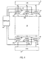
- the modular contactor assembly 10 includes electromagnetic contactors 12A-C for a three phase electrical system.
- Each contactor 12A-C is designed to switch current to a motor or other electrical device.
- contactors 12A-C are mounted to plate 11 configured to support each of the contactors as well as an optional cover (not shown).
- each of the contactors 12A-C of contactor assembly 10 is connected to facilitate connection to an overload relay 13A-C for use in a starter that operates in industrial control applications, such as motor control. Assembly 10 could equivalently be implemented without relays 13A-C for other applications.
- Apertures 14A-C located in each relay 13A-C, respectively, facilitate electrical connection of lead wires to the contactor assembly. Since each contactor/overload relay includes three apertures; a common bus plate (not shown) jumping all three apertures could be inserted for the end user to attach single point wiring.
- the bus plate may include lugs or ring terminals for the end user to connect wires to the assembly.
- this three-way connection for each phase is beneficial under fault conditions as the current for each phase A-C can be distributed evenly within each contactor to assist with minimizing contact arcing and contact erosion, especially on make.
- Each contactor 12A-C includes a top cover 16A-C that is secured to the contactor frame via screws 18A-C.
- Each relay 13A-C also includes a cover 20A-C that is snapped to the relay frame and is hinged to allow access to an FLA adjustment potentiometer (not shown).
- Each relay 13A-C includes a reset button 22A-C.
- FIG. 2 a longitudinal cross-sectional view of one of the contactors 12A-C of the modular contactor assembly 10 taken along line 2-2 of Fig. 1 is shown (without overload relay 13A-C from Figure 1).
- contactor 12A is cross-sectionally shown but a cross-sectional view of contactors 12B or 12C would be similar.
- Contactor 12A is shown in a normally open operating position prior to energization of an electromagnetic coil 24 with contacts 26, 28 separated and open.
- Coil 24 is secured by the contactor housing 30 and is designed to receive an energy source or an in-rush pulse at or above an activation power threshold that draws armature 32 into the magnet assembly 35.
- a movable contact carrier, secured to the armature 32, is also drawn towards magnet assembly 35.
- Magnet assembly 35 consists of a magnet post 36 firmly secured to magnet frame 86. Magnet post 36, magnet frame 86, and armature 32 are typically solid iron members.
- Coil 24 includes a molded plastic bobbin wound with copper magnet wire and is positioned centrally over magnet post 36 and inside magnet frame 86. Preferably, coil 24 is driven by direct current and is controlled by pulse width modulation to limit current and reduce heat generation in the coil.
- magnet assembly 35 attracts armature 32 that is connected to a movable contact carrier 39. Moveable contact carrier 39 along with armature 32 is guided towards magnet assembly 35 with guide pin 40 and molded housing 30 walls 46, 48.
- Guide pin 40 is press-fit or attached securely into armature 32 which is attached to movable contact carrier 39.
- Guide pin 40 is slidable along guide surface 42 within magnet assembly 35.
- the single guide pin 40 is centrally disposed and is utilized in providing a smooth and even path for the armature 32 and movable contact carrier 39 as it travels to and from the magnet assembly 35.
- Movable contact carrier 39 is guided at its upper end 44 by the inner walls 46, 48 on the contactor housing 30.
- Guide pin 40 is partially enclosed by an armature biasing mechanism or a resilient armature return spring 50, which is compressed as the movable contact carrier 39 moves toward the magnet assembly 35.
- Armature return spring 50 is positioned between the magnet post 36 and the armature 32 to bias the movable contact carrier 39 and armature 32 away from magnet assembly 35.
- a pair of contact bridge stops 52 limits the movement of the contact bridge 54 towards the arc shields 56 during a high fault current event.
- the combination of the guide pin 40 and the armature return spring 50 promotes even downward motion of the movable contact carrier 39 and assists in preventing tilting or window-locking that may occur during contact closure.
- the moveable contact carrier 39 and the armature 32 travel along guide surface 42 in order to provide a substantially even travel path for the moveable contact carrier 39.
- Three pairs of crimping lugs 58 are provided per contactor and used to secure lead wires to the contactor.
- a common busbar containing stationary contacts may be used as a base for end user wire connection either through ring terminals or appropriately sized lug.
- a lateral cross-sectional view of the contactor 12A is depicted in the normal open operating position prior to energization of the electromagnetic coil 24.
- the armature 32 is. biased by the resilient armature return spring 50 away from the magnet assembly 35 toward the housing stops 60 resulting in a separation between the armature and core.
- the contact carrier assembly also travels away from the magnet assembly 35 due to the armature biasing mechanism 50 which creates a separation between the movable contacts 28 and the stationary contacts 26 preventing the flow of electric current through the contacts 26, 28.
- Biasing springs 34 are connected to a top surface 62 of movable contact 64 and are extended such that a maximum space 63 results between the top of the spring and the movable contact 64.
- a pair of modular contactor assemblies 66 and 68 is shown as isolation devices connected to a softstarter 70.
- Contactor assembly 66 includes, in a three-phase application, three contactors 72A, 72B, 72C that carry power from a line power source 74 via lines A, B, and C, respectively.
- contactor assembly 68 also includes three contactors 76A, 76B, 76C for a three-phase load 78. As illustrated, there are three contactors within a single contactor assembly before and after the soft starter.
- Contactor assemblies 66 and 68 are designed to provide galvanic isolation to the soft starter by independently "breaking open” their contactors after the soft starter interrupts the circuit, or in the case of a shorted SCR in the softstarter, interrupts the load themselves (fault condition).
- Each contactor of contactor assembly 66, 68 includes multiple contacts.
- each contactor includes three contact assemblies and each contact assembly includes one line side contact, one load side contact, and one connecting or bridge contact for connecting the line and load side contacts to one another.
- the bridge contacts may be moveable contacts such as those previously described.
- Controller 80 is connected to an actuating assembly (not shown) in each contactor that is arranged to move the contact assemblies of each contactor in unison between an open and closed position.
- Each actuating assembly comprises a coil, armature, and magnetic components to effectuate "breaking" and “making” of the contacts, as was described above.
- Controller 80 is designed to transmit control signals to the actuating assemblies to independently regulate the operation of the contactors.
- the controller triggers the actuating assemblies based on current data received from a current sensing unit 82, that in the embodiment shown in Fig. 4, is constructed to acquire current data from first phase or pole A of the three-phase line input. While current sensing unit 82 is shown to acquire current data from first phase or pole A, current sensing unit 82 could be associated with the second or third phases or poles B and C of the three-phase line input.
- each contactor 72A-C and 76A-C has its own actuating assembly, each contactor may be independently opened and closed. This independence allows for one contactor to be opened without opening the remaining contactors of the modular contactor assembly. For example, a first contactor 72A, 76A can be opened and the remaining contactors 72B-C, 76B-C can be controlled to not open until the contacts of the first contactor 72A, 76A have cleared. This delay and subsequent contactor opening reduces arc erosion of the contacts of the subsequently opened contactors since each contactor can be controlled to open when the phase for that contactor is at or near a zero current point. Thus, arcing time is at a minimum.
- each contactor 72A-C, 76A-C includes three contact assemblies 84A-C, 86A-C.
- Each contact assembly is made up of movable contacts and stationary contacts.
- the contact assemblies within each contactor are constructed to open in unison and are therefore controlled by a common crossbar or bridge. As such, the contact assemblies within a single contactor operate in unison, but the contactors are asynchronously or independently operated with respect to another.
- controller 80 is connected to contactors 72A and 76A directly but is connected to contactors 76B-C and 76B-C in parallel. As such, contactors 72B-C and 76B-C can be controlled simultaneously.
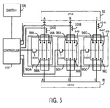
- contactor assembly 88 may be implemented as a switching device to control and protect a load 89 connected thereto.
- Contactor assembly 88 includes three contactors 90A-C. The number of contactors coincides with the number of phases of the line input 92 as well as load 89. Therefore, in the example of Fig. 5, a contactor is provided for each phase of the three-phase line 92 and load 89.
- Each contactor 90A-C includes three contact assemblies 94A-C.
- Each assembly 94A-C includes multiple line side contacts 96A-C and multiple load side contacts 98A-C.
- Each contactor includes an actuating assembly 100A-C that is connected to and controlled by a controller 102.
- Controller 102 controls breaking and making of the contacts of each contactor by triggering the actuating assembly in the contactor based on fault data received from transducers 104A-C. Alternately, breaking and making of the contacts could be controlled by an override control or switch 106.
- each contactor The timing of the breaking of each contactor is determined based on current data received from transducers 104A-C.
- transducers 104A-C In a three-phase input environment, three transducers 104A, 104B, and 104C are used.
- each contactor may be identified as the "first" pole contactor, as will be described in greater detail below.
- only one transducer may be implemented to collect current data from one phase and the contactor corresponding to that phase would be considered the "first" pole contactor.
- any contactor can be the "first" pole contactor.
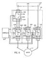
- a contactor assembly 108 is shown in a typical motor control application configuration between a power line source 110 and a three-phase motor 112.
- Contactor assembly 108 is a modular contactor assembly and includes four contactors 114A, A', B, C similar to the contactors heretofore described.
- Each contactor 114A-C includes a set of contact assemblies 116A-C.
- each contact assembly includes a set of line side contacts 118A-C and load side contacts 120A-C.
- Each contactor also includes an actuating assembly 122A-C that breaks and makes the contact assemblies of each respective contactor in unison. However, since each contactor has its own actuating assembly, the contactors can be independently controlled.
- Controller 124 opens and closes each contactor based on the corresponding phase A-C of the contactor crossing a particular current value or voltage value. In one embodiment, each contactor is controlled to open when the current in the corresponding phase is approximately zero. Opening of the contacts of the contactor at or near a zero current reduces the likelihood of arc erosion between the contacts of the contactor. However, controller 124 can be configured to independently open the contactors based on the current in the corresponding phase reaching/crossing a particular non-zero value. Current data is acquired by at least one current sensor (not shown) connected between the line 110 and the contactors 114A-C.
- contactors 114A and 114A' are shown as being serially connected to another.
- This configuration has a number of advantages, particularly for high voltage applications (i.e. greater than 600 V). Connecting two contactors in series and designating the two contactors as the first contactors to open when a fault is detected or open command is issued allows the two serially connected contactors 114A,A' to share high switching energy stress. As a result, more energy is dissipated in the contactors 114A,A' thereby reducing the energy absorption burden of contactors 114B,C.
- contactors 114A,A' are also connected to the controller in parallel with another, the controller can cause contactors 114A,A' to open simultaneously. This results in a greater arc voltage being generated by the four arcs as opposed to a conventional double break system and reduces the current and contact erosion. The multiple contact gaps also reduce the likelihood of reignitions after current zero.
- Fig. 6 shows an embodiment of the present invention; however, additional configurations not shown are contemplated and within the scope of this invention.
- three sets of two serially connected contactors may be arranged in parallel and independently controlled.
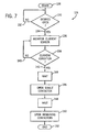
- the modular contactor assembly includes multiple contactors that are independently opened by an actuating mechanism controlled by a controller based on current data acquired from one or more current sensors. Since the contactors have a unique actuating assembly, the contactors can be controlled in accordance with a number of control techniques or algorithms. Some of these control schemes will be described with respect to Figs. 7-9.
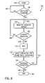
- Fig. 7 the steps of a control technique or algorithm for a modular contactor assembly in accordance with the present invention is shown.
- the steps carried out in accordance with technique 126 are equivalently applicable with a modular isolation contactor, a modular heating load contactor, a modular on-demand switching contactor, and the like.
- the steps begin at 128 with identification that an open condition is desired 130. Identification of a desired open condition may be the result of either a dedicated switch open command or a fault indicator signal indicating that a fault condition is present and at least one contactor should be opened. If an open condition is not desired 130, 132, the technique recycles until an open condition is desired 134.
- the current condition in one embodiment, is a current zero in the monitored phase of the three-phase input.
- Wait step 144 is a time delay and is based on the time required from the actuating assembly receiving the switch open signal to the actual contact separation of the corresponding contactor. After the time delay has expired 144, a switch or break open signal is sent to the actuating assembly for a single contactor at step 146. The multiple contact assemblies for the contactor are then caused to open and, as such, an open circuit is created between the line and load for the corresponding phase of the three-phase input.
- a wait step 148 is once again undertaken.
- the waiting period at step 148 is of sufficient length to insure that the single contactor has opened before the remaining contactors of the contactor assembly are opened at 150.
- the contacts of the single contactor are opened one to two milliseconds before current zero.
- all of the contactors are opened and an open circuit between the line and load is created 152.
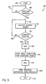
- technique 154 for controlling modular contactors in a single contactor assembly begins at step 156, and awaits a desired open switching or fault command at step 158. If an open condition is not desired 158,160, technique 154 recycles until an open condition is desired 158,162. When an open condition is desired, current in each phase of the three-phase input signal is monitored at 164. As such, technique 154 is particularly applicable with a modular contactor assembly dedicated for controlled switching wherein each phase has a dedicated current sensor or transducer, similar to that described with respect to Fig. 5.
- the current condition is preferably defined as the next current zero in the phase following receipt of the switching or fault indicator signal. However, the current condition could also be any non-zero point on the current wave.
- technique 154 undergoes a wait or hold step at 172.
- the time period of the wait step 172 is a delay time based on the time required from an actuating assembly receiving an open contactor signal for that contactor to the actual breaking of the contacts in the contactor.
- the contactor for the phase in which the current zero condition was identified is opened at step 174.
- the contact assemblies of the contactor are opened in unison one to two milliseconds before the next current zero in the phase corresponding thereto.
- step 174 a determination is made as to whether there are additional contactors that are unopened 176. If so 176, 178, technique 154 returns to step 162 wherein current is monitored in the phases of the closed contactors. As such, each contactor is independently opened with respect to one another. Because the second and third phase current will have the same phase angle after the first phase is cleared, the contactors in the last two phases will open simultaneously. Once all the contactors are opened 176, 180, the process concludes at step 100 with all of the contactors being in an opened or broken state.
- a technique or process 184 particularly applicable to independently controlling contactors of a modular isolation contactor assembly begins at 186, and at step 188 a switching or fault command indicative of a desired open condition is identified. If an open condition is not desired 188, 190, the process recycles until such a command is received. Failure to receive such command is indicative of a desire for continued electrical connection between a line and a load.
- a switching or fault indicator signal or command is received 188, 192, current is monitored using a current sensor in one phase of a three-phase input signal. Any phase of a three-phase input may be monitored but, preferably, only one phase is, in fact, monitored. Current in the phase is monitored to determine when a specified current condition occurs 114.
- the current condition is defined as a current zero signal being received from the current sensor based on the monitored phase crossing a current zero point.
- a non-zero point on the current signal could also be considered the specified current condition.
- the process continues monitoring current in the selected phase. Once the current condition occurs and is identified by the controller 196, 200, the process implements a wait step 202 before the controller transmits a break open signal to an actuating assembly for the single contactor corresponding to the monitored phase. The wait or delay period is based on a time interval required from the actuating assembly receiving the signal to the breaking open of the corresponding contactor.
- the contactor corresponding to the monitored phase is opened at 204.
- the contactor is broken at a point one to two milliseconds before the next current zero in the corresponding phase.
- the process waits until the multiple contacts have opened before opening the remaining contactor at step 208.
- the remaining contactors are opened simultaneously. For example, in a three-phase environment, a first pole contactor would be opened and subsequent thereto the contactors for the second and third poles, respectively, would be simultaneously opened by their respective actuating assemblies. Once all the contactors are opened, the line and load are isolated from each other and the process ends 210.
- POW switching allows the contacts of a contactor to be closed based on voltage data acquired from a voltage sensor and be opened based on current data acquired from a current sensor. POW switching reduces contact erosion and therefore improves contact switching by breaking open the contacts of the contactor in such a manner as to minimize or prevent an arc being formed between the contacts. For closing of the contacts, POW switching is also beneficial in reducing negative torque oscillations in the motor (load) by closing the contacts at precise voltage points.
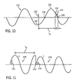
- a typical sinusoidal current waveform 212 for a single phase of a three-phase power signal is shown.
- the value of the current varies along each point of the waveform from a maximum negative current value 214 to a maximum positive current value 216. Between successive minimum values (or maximum values), the waveform crosses a zero point 218. At point 218, the current for the corresponding phase being applied to the load is at or near a minimum. As discussed above, it is desirable to open a contactor when the current waveform is at or near point 218 to reduce an arc being formed between the contacts of the contactor.
- Waveform 212 is generally constant as power is supplied to the load. Variations in magnitude, frequency, and phase will occur over time, but waveform 212 is generally constant.
- a switching command or fault indicator signal 220 is received.
- the switching signal is shown relative to the current waveform and corresponds to when the waveform is at point 214. However, this is for illustrative purposes only and the switching or open signal can be received at any point in the current continuum. If the contacts were opened the moment the open condition was desired (switching signal received), the magnitude of the current at that point would be at or near a maximum. This would increase the break arcing time and subsequent contact erosion.
- the controller delays the opening of the contactor by an interval t d .
- the contacts of the contactor are opened.
- An open circuit condition between the line and the load for that phase does not immediately occur.
- the short duration of break arc occurs and helps to minimize contact erosion and to prevent reignition after current zero, as was discussed above.
- the contactor is opened and an open condition between the line and load is achieved.
- Point-on-wave switching is an advantage of the present invention.
- the purpose of point-on-wave closing is to minimize the asymmetric component in the make currents so to reduce negative torque oscillations in a motor (load) as well as to minimize the bounce arc erosion and contact welding.
- Fig. 11 a set of voltage and current waveforms 228, 229, respectively, for a single phase of a three phase power signal is shown to illustrate "making" or closing of a contactor in accordance with the present invention.
- the designated 1 st pole to close does not need to "make” at any specific phase angle of the system voltage since there will be no current flow through the contactor.
- the 2nd and 3 rd poles close at a specific point on the voltage wave form to reduce negative torque oscillations.
- Making of the contacts in each of the 2 nd and 3 rd contactors is based on at least one voltage data value from a voltage sensor, and in the illustrated example, a close contactor signal is received at point 230 on the waveform.
- a delay period t d is observed whereupon only after the designated first pole contactor is closed.
- the contacts of a second contactor are closed at point 232 which is preferably within a 65 to 90 degree phase angle of the system voltage depending on the power factor of the load.
- Arcing due to contact bounce can also be minimized or eliminated by using multiple sets of contacts in each contactor. Reducing bounce arc 234 is advantageous as it also leads to contact erosion and contact welding. Controlling when the contacts are closed also reduces negative torque oscillations in the motor.
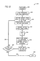
- the steps of a technique or process of "making" or closing contactors independently of a modular or multi-contactor assembly are set forth in Fig. 12.
- the technique 236 begins at 238 with a switching command being sent from the controller to the actuating assembly or assemblies for the designated first pole contactor 238.
- the designated first pole contactor may be closed independent of the specific phase angle of the system voltage because there is no current flowing through the contactor prior to its closing.
- the actuating assembly for the designated first pole contactor causes the contacts within the contactor to close at 240.
- the present technique 236 may be implemented with a contactor having a single actuating assembly or more than one actuating assembly. Additionally, while it is preferred that each contactor includes multiple sets of contacts, the present technique 236 may be implemented with a contactor having a single set of contacts.
- a defined phase angle of the system voltage in the phase corresponding to a non-first pole contactor is monitored at 242.
- the non-first pole contactor may be closed at a specified point on the waveform.
- a signal indicative of the defined phase angle in the system voltage corresponding to the non-first pole contactor is transmitted to the controller at 244.
- the defined phase angle signal may be transmitted from a voltage sensor or other detection or sensory device.
- the controller waits until expiration of a delay time at 246.
- the delay time is based on the amount of time required from the actuating assemblies of a contactor receiving a switching signal to the closing of the contacts in a contactor.
- the controller Upon expiration of the time delay, the controller sends a close contact signal to the actuating assemblies of the non-first pole contactor 248 thereby causing the contacts of the non-first pole contactor to close at 250.
- the non-first pole contactor is preferably closed between approximately 65 degrees to approximately 90 degrees of the phase angle of the system voltage depending upon the power factor of the load.
- technique 236 ends at 258 with current flowing through each of the contactors.
- the controller implements one of the techniques or processes previously described with respect to Figs. 7, 8, or 9 to independently control the opening of the contactors of the contactor assembly when an open condition is desired.
- the present invention has been described with respect to designated first pole switching wherein the contactor for one pole or phase of a three-phase input or load is broken or opened before the remaining contactors are opened.
- An advantage of this construction is that any contactor may be designated the "first" pole contactor. Further, this designation can be selectively changed such that the "first" pole designation is rotated among all the contactors. Rotating the "first" pole designation between the contactor evens out contact erosion between the contactors thereby achieving constant and consistent operation of the contactors.
- the rotation designation can be automatically done by programming the controller to change designation after a specified number of makes and break events or manually by changing the order the lead wires are connected to the contactor assembly.
- the present invention includes an apparatus for protecting a poly-phase electrical device from current overloading.
- the apparatus includes at least one first pole contactor, at least one second pole contactor, and at least one third pole contactor.
- Each contactor has multiple contact assemblies that are associated with a single phase of a poly-phase input such that each contact assembly of a contactor is directly connected to a common phase of the poly-phase input.
- a controller is provided to independently control the at least one first pole contactor, the at least one second pole contactor, and the at least one third pole contactor.
- the present invention includes a contactor assembly having at least four sets of contacts connectable to a three-phase power source. Two of the contacts are in series with one another in one phase and in parallel with two other sets of contacts in the other two phases. A controller is connected to open the two sets of contacts connected in series before the other sets of contacts connected in parallel.
- an electrical switching apparatus includes a number of contactors housed within a single contactor housing.
- One of the contactors is a designated first pole contactor and is configured to regulate a single phase of current supplied to a poly-phase load from a poly-phase source.
- the apparatus further includes a controller configured to control the number of contactors such that the first pole contactor is caused to open independently of the other contactors.
Landscapes
- Engineering & Computer Science (AREA)
- Power Engineering (AREA)
- Physics & Mathematics (AREA)
- Electromagnetism (AREA)
- Relay Circuits (AREA)
- Switch Cases, Indication, And Locking (AREA)
- Breakers (AREA)
- Keying Circuit Devices (AREA)
Applications Claiming Priority (2)
| Application Number | Priority Date | Filing Date | Title |
|---|---|---|---|
| US249206 | 2003-03-21 | ||
| US10/249,206 US7196434B2 (en) | 2003-03-21 | 2003-03-21 | Modular contactor assembly having independently controllable contractors |
Publications (1)
| Publication Number | Publication Date |
|---|---|
| EP1460663A1 true EP1460663A1 (fr) | 2004-09-22 |
Family
ID=32823597
Family Applications (1)
| Application Number | Title | Priority Date | Filing Date |
|---|---|---|---|
| EP20040006236 Withdrawn EP1460663A1 (fr) | 2003-03-21 | 2004-03-16 | Interrupteur modulaire avec interrupteurs commandés independamment |
Country Status (5)
| Country | Link |
|---|---|
| US (1) | US7196434B2 (fr) |
| EP (1) | EP1460663A1 (fr) |
| BR (1) | BRPI0400955A (fr) |
| CA (1) | CA2461314C (fr) |
| MX (1) | MXPA04002620A (fr) |
Cited By (1)
| Publication number | Priority date | Publication date | Assignee | Title |
|---|---|---|---|---|
| US11538640B2 (en) * | 2019-09-30 | 2022-12-27 | Rockwell Automation Technologies, Inc. | Systems and methods for relay contact assembly reduction |
Families Citing this family (21)
| Publication number | Priority date | Publication date | Assignee | Title |
|---|---|---|---|---|
| FR2977066B1 (fr) * | 2011-06-27 | 2016-12-30 | Schneider Electric Ind Sas | Appareil de protection electrique comportant au moins un module de coupure commande par un dispositif de commande a bobine electromagnetique |
| US9590536B2 (en) | 2013-03-15 | 2017-03-07 | Rockwell Automation Technolgies, Inc. | Two-step connection of electric motors by means of electromagnetic switches |
| US9396898B2 (en) * | 2013-03-15 | 2016-07-19 | Rockwell Automation Technologies, Inc. | Multipole electromechanical switching device |
| US9425011B2 (en) * | 2013-08-26 | 2016-08-23 | General Electric Company | Method and system for soft switching of a relay |
| KR101741586B1 (ko) * | 2014-10-31 | 2017-05-30 | 엘에스산전 주식회사 | 전자접촉기 크로스바 구조 |
| US9806642B2 (en) | 2014-11-06 | 2017-10-31 | Rockwell Automation Technologies, Inc. | Modular multiple single-pole electromagnetic switching system and method |
| US10018676B2 (en) | 2014-11-06 | 2018-07-10 | Rockwell Automation Technologies, Inc. | Electromagnetic switch interlock system and method |
| US9806641B2 (en) | 2014-11-06 | 2017-10-31 | Rockwell Automation Technologies, Inc. | Detection of electric motor short circuits |
| US10361051B2 (en) | 2014-11-06 | 2019-07-23 | Rockwell Automation Technologies, Inc. | Single pole, single current path switching system and method |
| US9748873B2 (en) | 2014-11-06 | 2017-08-29 | Rockwell Automation Technologies, Inc. | 5-pole based wye-delta motor starting system and method |
| US10074497B2 (en) | 2014-11-06 | 2018-09-11 | Rockwell Automation Technologies, Inc. | Operator coil parameter based electromagnetic switching |
| US9722513B2 (en) | 2014-11-06 | 2017-08-01 | Rockwell Automation Technologies, Inc. | Torque-based stepwise motor starting |
| US10141143B2 (en) | 2014-11-06 | 2018-11-27 | Rockwell Automation Technologies, Inc. | Wear-balanced electromagnetic motor control switching |
| US10320313B2 (en) * | 2015-03-10 | 2019-06-11 | Young Jun Kim | Arc free phase control alternatives for AC motor starters |
| US10083809B2 (en) | 2016-04-21 | 2018-09-25 | Hartland Controls, Llc | Electrical power transfer switch |
| US9865416B2 (en) | 2016-04-21 | 2018-01-09 | Hartland Controls, Llc | Electrical power transfer switch |
| JP6176364B1 (ja) * | 2016-06-14 | 2017-08-09 | 富士電機機器制御株式会社 | 接点装置及びこれを使用した電磁接触器 |
| JP6332480B1 (ja) * | 2017-01-11 | 2018-05-30 | 富士電機機器制御株式会社 | 電磁接触器 |
| EP3410458B1 (fr) * | 2017-06-02 | 2019-05-22 | Sick AG | Circuit à relais de sécurité modulaire destiné à sécuriser et/ou désactiver au moins une machine |
| DE102017220503B3 (de) * | 2017-11-16 | 2019-01-17 | Te Connectivity Germany Gmbh | Doppelt unterbrechender Schalter |
| ES2937173T3 (es) | 2019-03-29 | 2023-03-24 | Abb Schweiz Ag | Método para realizar una operación de cierre e interrupción de circuito |
Citations (8)
| Publication number | Priority date | Publication date | Assignee | Title |
|---|---|---|---|---|
| US3292047A (en) * | 1963-07-12 | 1966-12-13 | Westinghouse Electric Corp | Circuit breaker control circuit |
| US3310640A (en) * | 1964-11-11 | 1967-03-21 | Reinhausen Maschf Scheubeck | High current-carrying capacity switching devices requiring small contact pressures |
| US3566152A (en) * | 1969-07-23 | 1971-02-23 | Gen Electric | High voltage electric circuit breaker including a synchronously closed resistor switch |
| US5172291A (en) * | 1990-03-27 | 1992-12-15 | Struthers-Dunn, Inc. | Intelligent power controller |
| US5440180A (en) * | 1992-09-28 | 1995-08-08 | Eaton Corporation | Microprocessor based electrical contactor with distributed contactor opening |
| FR2737040A1 (fr) * | 1995-07-21 | 1997-01-24 | Sait Mining | Coupe-circuit multipolaire haute intensite presentant une coupure au voisinage de zero du courant sur tous les contacts |
| US5644463A (en) * | 1992-10-20 | 1997-07-01 | University Of Washington | Adaptive sequential controller with minimum switching energy |
| US5771145A (en) * | 1996-12-17 | 1998-06-23 | General Electric Company | Zero current circuit interruption |
Family Cites Families (25)
| Publication number | Priority date | Publication date | Assignee | Title |
|---|---|---|---|---|
| US3934110A (en) | 1974-03-11 | 1976-01-20 | Denis Albert P | Welding system and method for arc starting and control |
| US3982137A (en) | 1975-03-27 | 1976-09-21 | Power Management Corporation | Arc suppressor circuit |
| US4019017A (en) | 1975-04-14 | 1977-04-19 | Leco Corporation | Arc control circuit |
| US4056836A (en) | 1976-03-23 | 1977-11-01 | Hughes Aircraft Company | Method and apparatus for interrupting large current |
| US4128749A (en) | 1976-09-07 | 1978-12-05 | Spaderna Conan H | Latching switch |
| US4234901A (en) * | 1979-03-08 | 1980-11-18 | Westinghouse Electric Corp. | Protective relay apparatus |
| NL176724C (nl) | 1979-06-11 | 1985-05-17 | Hazemeijer Bv | Beveiligingsinrichting voor het selektief afschakelen van netgedeelten van een elektrisch energieverdeelnet, alsmede een energieverdeelnet voorzien van meerdere selectieve beveiligingsinrichtingen. |
| US4398097A (en) | 1979-12-10 | 1983-08-09 | Indian Head, Inc. | Automatic transfer switch |
| US4445018A (en) | 1982-01-07 | 1984-04-24 | Mcgraw-Edison Company | Energy efficient floating head puffer interrupter |
| US4491708A (en) | 1982-09-07 | 1985-01-01 | S&C Electric Company | Electrical contact for use in a current interrupting unit |
| US4525762A (en) | 1983-10-07 | 1985-06-25 | Norris Claude R | Arc suppression device and method |
| US4642481A (en) | 1985-08-08 | 1987-02-10 | Eaton Corporation | Solid state hybrid switch |
| US4959746A (en) | 1987-01-30 | 1990-09-25 | Electronic Specialty Corporation | Relay contact protective circuit |
| US4864157A (en) | 1988-05-12 | 1989-09-05 | Spatron Corporation | Reduced arcing contact switching circuit |
| JPH0652761A (ja) | 1992-08-01 | 1994-02-25 | Mitsubishi Electric Corp | 開閉器 |
| FR2706072B1 (fr) | 1993-06-02 | 1995-07-13 | Telemecanique | Appareil électromécanique interrupteur à commutation d'arc. |
| JP3506590B2 (ja) * | 1997-10-03 | 2004-03-15 | 三菱電機株式会社 | モータの非常停止装置 |
| US5959517A (en) | 1998-07-21 | 1999-09-28 | Eaton Corporation | Fault current tolerable contactor |
| US6087800A (en) | 1999-03-12 | 2000-07-11 | Eaton Corporation | Integrated soft starter for electric motor |
| DE10037383A1 (de) * | 2000-08-01 | 2002-02-21 | Pilz Gmbh & Co | Sicherheitsschaltgerät zum sicheren Abschalten eines elektrischen Verbrauchers, insbesondere einer elektrisch angetriebenen Maschine |
| US6600238B1 (en) * | 2000-11-20 | 2003-07-29 | International Business Machines Corporation | Redundancy and component failure detection within a switching power system |
| US6377143B1 (en) | 2001-03-16 | 2002-04-23 | Eaton Corporation | Weld-free contact system for electromagnetic contactors |
| US6837729B2 (en) * | 2002-09-10 | 2005-01-04 | Tyco Electronics Corporation | High power electrical contactor with improved bridge contact mechanism |
| US6797900B2 (en) * | 2002-09-19 | 2004-09-28 | Drew Hoffman | Modular contact switch |
| US6956728B2 (en) * | 2003-02-28 | 2005-10-18 | Eaton Corporation | Method and apparatus to control modular asynchronous contactors |
-
2003
- 2003-03-21 US US10/249,206 patent/US7196434B2/en not_active Expired - Lifetime
-
2004
- 2004-03-16 EP EP20040006236 patent/EP1460663A1/fr not_active Withdrawn
- 2004-03-17 CA CA 2461314 patent/CA2461314C/fr not_active Expired - Fee Related
- 2004-03-19 MX MXPA04002620A patent/MXPA04002620A/es active IP Right Grant
- 2004-03-22 BR BRPI0400955 patent/BRPI0400955A/pt not_active Application Discontinuation
Patent Citations (8)
| Publication number | Priority date | Publication date | Assignee | Title |
|---|---|---|---|---|
| US3292047A (en) * | 1963-07-12 | 1966-12-13 | Westinghouse Electric Corp | Circuit breaker control circuit |
| US3310640A (en) * | 1964-11-11 | 1967-03-21 | Reinhausen Maschf Scheubeck | High current-carrying capacity switching devices requiring small contact pressures |
| US3566152A (en) * | 1969-07-23 | 1971-02-23 | Gen Electric | High voltage electric circuit breaker including a synchronously closed resistor switch |
| US5172291A (en) * | 1990-03-27 | 1992-12-15 | Struthers-Dunn, Inc. | Intelligent power controller |
| US5440180A (en) * | 1992-09-28 | 1995-08-08 | Eaton Corporation | Microprocessor based electrical contactor with distributed contactor opening |
| US5644463A (en) * | 1992-10-20 | 1997-07-01 | University Of Washington | Adaptive sequential controller with minimum switching energy |
| FR2737040A1 (fr) * | 1995-07-21 | 1997-01-24 | Sait Mining | Coupe-circuit multipolaire haute intensite presentant une coupure au voisinage de zero du courant sur tous les contacts |
| US5771145A (en) * | 1996-12-17 | 1998-06-23 | General Electric Company | Zero current circuit interruption |
Cited By (2)
| Publication number | Priority date | Publication date | Assignee | Title |
|---|---|---|---|---|
| US11538640B2 (en) * | 2019-09-30 | 2022-12-27 | Rockwell Automation Technologies, Inc. | Systems and methods for relay contact assembly reduction |
| US11756748B2 (en) | 2019-09-30 | 2023-09-12 | Rockwell Automation Technologies, Inc. | Systems and methods for relay contact assembly reduction |
Also Published As
| Publication number | Publication date |
|---|---|
| US7196434B2 (en) | 2007-03-27 |
| CA2461314A1 (fr) | 2004-09-21 |
| CA2461314C (fr) | 2012-03-13 |
| MXPA04002620A (es) | 2004-09-23 |
| BRPI0400955A (pt) | 2004-12-07 |
| US20060274459A1 (en) | 2006-12-07 |
Similar Documents
| Publication | Publication Date | Title |
|---|---|---|
| CA2459108C (fr) | Methode et dispositif de commande de contacteurs asynchrones modulaires | |
| CA2488446C (fr) | Methode et appareil permettant de commander separement des contacteurs dans une configuration a plusieurs contacteurs | |
| EP1662524A2 (fr) | Procédé et appareil pour contrôler des contacteurs modulaires asynchrones | |
| CA2461314C (fr) | Ensemble de contacteurs modulaires a commande independante | |
| US7057311B1 (en) | Isolation contactor assembly having independently controllable contactors | |
| EP1492142A2 (fr) | Procédé et système de control de contacteurs asynchrones pour une charge poly-phasée | |
| EP1944779B1 (fr) | Démarreur de moteur électrique basé sur un système micro-électromécanique | |
| JP5346551B2 (ja) | 超小型電気機械システムをベースにしたスイッチング | |
| US4152634A (en) | Power contactor and control circuit | |
| US4025883A (en) | Modular integral motor controller | |
| EP0418919B1 (fr) | Appareil et méthode de commande pour plusieurs circuits | |
| JPS62249312A (ja) | 高速限流回路遮断器 | |
| CA2475556C (fr) | Ensemble de contacteurs d'isolement comprenant des contacteurs commandes separement | |
| CA1086850A (fr) | Relais de puissance et circuit de commande | |
| WO2024085977A1 (fr) | Contacteur haute tension à point unique fusionné à déconnexion rapide | |
| SU1524149A1 (ru) | Устройство дл управлени асинхронным электродвигателем | |
| PL126077B1 (en) | Method of and system for arcless switching off alternating currents using hybrid diode contactors driven with electromagnets |
Legal Events
| Date | Code | Title | Description |
|---|---|---|---|
| PUAI | Public reference made under article 153(3) epc to a published international application that has entered the european phase |
Free format text: ORIGINAL CODE: 0009012 |
|
| AK | Designated contracting states |
Kind code of ref document: A1 Designated state(s): AT BE BG CH CY CZ DE DK EE ES FI FR GB GR HU IE IT LI LU MC NL PL PT RO SE SI SK TR |
|
| AX | Request for extension of the european patent |
Extension state: AL LT LV MK |
|
| 17P | Request for examination filed |
Effective date: 20050302 |
|
| AKX | Designation fees paid |
Designated state(s): DE FR GB IT |
|
| 17Q | First examination report despatched |
Effective date: 20050606 |
|
| STAA | Information on the status of an ep patent application or granted ep patent |
Free format text: STATUS: THE APPLICATION IS DEEMED TO BE WITHDRAWN |
|
| 18D | Application deemed to be withdrawn |
Effective date: 20060817 |