EP1460453A1 - Three-dimension vision system - Google Patents
Three-dimension vision system Download PDFInfo
- Publication number
- EP1460453A1 EP1460453A1 EP03006049A EP03006049A EP1460453A1 EP 1460453 A1 EP1460453 A1 EP 1460453A1 EP 03006049 A EP03006049 A EP 03006049A EP 03006049 A EP03006049 A EP 03006049A EP 1460453 A1 EP1460453 A1 EP 1460453A1
- Authority
- EP
- European Patent Office
- Prior art keywords
- vision system
- dimensional vision
- pulse
- equal
- sequence
- Prior art date
- Legal status (The legal status is an assumption and is not a legal conclusion. Google has not performed a legal analysis and makes no representation as to the accuracy of the status listed.)
- Granted
Links
Images
Classifications
-
- G—PHYSICS
- G01—MEASURING; TESTING
- G01S—RADIO DIRECTION-FINDING; RADIO NAVIGATION; DETERMINING DISTANCE OR VELOCITY BY USE OF RADIO WAVES; LOCATING OR PRESENCE-DETECTING BY USE OF THE REFLECTION OR RERADIATION OF RADIO WAVES; ANALOGOUS ARRANGEMENTS USING OTHER WAVES
- G01S17/00—Systems using the reflection or reradiation of electromagnetic waves other than radio waves, e.g. lidar systems
- G01S17/02—Systems using the reflection of electromagnetic waves other than radio waves
- G01S17/06—Systems determining position data of a target
- G01S17/08—Systems determining position data of a target for measuring distance only
- G01S17/10—Systems determining position data of a target for measuring distance only using transmission of interrupted, pulse-modulated waves
-
- G—PHYSICS
- G01—MEASURING; TESTING
- G01S—RADIO DIRECTION-FINDING; RADIO NAVIGATION; DETERMINING DISTANCE OR VELOCITY BY USE OF RADIO WAVES; LOCATING OR PRESENCE-DETECTING BY USE OF THE REFLECTION OR RERADIATION OF RADIO WAVES; ANALOGOUS ARRANGEMENTS USING OTHER WAVES
- G01S17/00—Systems using the reflection or reradiation of electromagnetic waves other than radio waves, e.g. lidar systems
- G01S17/88—Lidar systems specially adapted for specific applications
- G01S17/89—Lidar systems specially adapted for specific applications for mapping or imaging
Definitions
- the purpose of the present invention is to provide a three-dimensional vision system of the type specified above which will be capable of reconstructing a scene comprised within a field of view FOV and with a field depth limited between a value d min and a value d max .
- the duration ⁇ t f of each window is equal to the duration of the pulse ⁇ t of the source.
- the aforesaid transmission module can be based upon a single laser or a laser array, upon a single LED or a LED array, or upon any other light source, preferably with emission in the near IR (0.78 ⁇ m to 1.1 ⁇ m) or else in the infrared.
- the receiver module is preferably a CCD sensor array or a CMOS sensor array.
- the transmission module can be scanned either mechanically or electronically.
- the receiver module is made up of a single sensor scanned either mechanically or electro-optically.
- the reference number 1 designates, as a whole, the transmission module of the system according to the invention
- the reference number 2 designates the receiver module, which receives the signal reflected by an obstacle forming part of the scene that is impinged upon by the radiation emitted by the transmission module 1.
- the transmission module 1 and the receiver module 2 are electronic processing-synchronization means 3.
- T 0 2D/c where c is the speed of light.
- the time T 0 is also the maximum time taken by the light pulse to be detected if it has been reflected by objects at a distance not greater than D.
- the transmission module 1 emits a first light pulse of duration ⁇ t.
- k is a real number.
- the transmitted pulse impinges upon an obstacle, is reflected, and a percentage of the pulse (which depends upon the distance, the reflectivity, etc.) bounces back and is detected by the receiver 2.
- the number of electrons integrated in each individual window depends upon the background signal and upon the intensity of the echo signal received, which, in turn, depends upon the reflectivity and upon the distance of the object (see Figure 4).
- the integration window for the acquisition of the background can also be temporally out of phase with respect to the preceding one in such a way as not to collect the echo radiation coming from obstacles set in the range of distance of interest and as to collect only the radiation corresponding to the background.
- each sequence corresponding to the window for collecting the echo signal must necessarily be temporally out of phase with respect to the preceding one by a time interval equal to the duration of the window itself, the sequence corresponding to the window for collecting the background signal can be out of phase by a greater amount.
- the formula for the measurement of the distance contains the ratio between the number of electrons integrated in the windows of interest: the result is therefore already independent of the reflectivity of the object, and only depends upon the distance thereof from the receiver.
- the error on the individual quantities n j depends upon various factors: shot noise, dark noise, reset noise, etc. In the case of the invention, just the shot noise of the signal is taken into account, which, in conditions of normal light intensity, is the dominant contribution.
- ⁇ d D/k/ (n i+1 + n i - 2N) ⁇ (2n i + n i+1 + 5N)
- n k takes place by serial integration of the signal in the individual windows for a large number of times.
- the symbol of approximation depends upon the fact that some factors of delay, such as for example the read times, have been neglected.
Abstract
Description
- The present invention relates to the field of three-dimensional vision systems of the type comprising:
- a transmission module, which includes a light source;
- a receiver module, which comprises at least one photosensitive element operating in the same spectral window as the transmission module for detecting the radiation reflected by an obstacle which receives the radiation emitted by the transmission module; and
- control and processing electronic means associated to the receiver module.
- The purpose of the present invention is to provide a three-dimensional vision system of the type specified above which will be capable of reconstructing a scene comprised within a field of view FOV and with a field depth limited between a value dmin and a value dmax.
- In order to achieve the above purpose, the system according to the invention is characterized in that the transmission module is made up of a pulsed source, which, for each three-dimensional recording, emits N = m x n pulses of duration Δt, with repetition frequency f = dc/Δt (dc being the duty cycle of the source signal), and in that the aforesaid control and processing electronic means comprise processing-synchronization means capable of carrying out:
- a) integration of the echo pulse train in n sequences of integration windows of duration Δtf, each sequence, which is made up of m windows with repetition frequency f, being temporally out of phase with respect to the preceding one by a time duration equal to Δt, and the phase difference between the first window of the first sequence and the rising edge of the first transmitted pulse being equal to σ; and
- b) calculation of the distance covered, obtained by weighing the levels of the integrated signals for the various sequences, and on the basis of the extrapolation of the time of flight of the pulse (equal to the distance in time between the instant of emission and the rising edge of the echo pulse), the integrated-signal level in each sequence depending upon the percentage of pulse that is integrated in the sequence, the said value depending upon the instant of arrival of the pulse.
- In the preferred embodiment of the invention, the three-dimensional vision system is designed so as to have a duration Δt of the pulse equal to:

- Once again according to the preferred embodiment, the duration Δtf of each window is equal to the duration of the pulse Δt of the source.
- The aforesaid transmission module can be based upon a single laser or a laser array, upon a single LED or a LED array, or upon any other light source, preferably with emission in the near IR (0.78 µm to 1.1 µm) or else in the infrared.
- The receiver module is preferably a CCD sensor array or a CMOS sensor array.
- The transmission module can be scanned either mechanically or electronically.
- Alternatively, the receiver module is made up of a single sensor scanned either mechanically or electro-optically.
- Further characteristics and advantages of the invention will emerge clearly from the ensuing description with reference to the annexed drawings, which are provided purely by way of non-limiting example and in which:
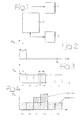
- Figure 1 is a block diagram of the three-dimensional vision system according to the invention; and
- Figures 2, 3, and 4 are diagrams illustrating the basic principles of the vision system according to the invention.
- With reference to Figure 1, the
reference number 1 designates, as a whole, the transmission module of the system according to the invention, whilst thereference number 2 designates the receiver module, which receives the signal reflected by an obstacle forming part of the scene that is impinged upon by the radiation emitted by thetransmission module 1. Associated to thetransmission module 1 and thereceiver module 2 are electronic processing-synchronization means 3. - Briefly described in what follows is the theoretical principle underlying the system according to the invention.
- Assuming the need to measure the distance of objects in a range D, the time taken for a light signal to cover a range 2D is:

- The time T0 is also the maximum time taken by the light pulse to be detected if it has been reflected by objects at a distance not greater than D.
- In the system according to the invention, at the instant T0 = 0 the
transmission module 1 emits a first light pulse of duration Δt. There is imposed the need for Δt to be an integer submultiple of T0, i.e., such as to satisfy the relation (k-1)Δt = T0, where k is a real number. The said situation is illustrated in the diagram of Figure 2. - The transmitted pulse impinges upon an obstacle, is reflected, and a percentage of the pulse (which depends upon the distance, the reflectivity, etc.) bounces back and is detected by the
receiver 2. At the same instant t0 = 0, the receiver begins to integrate the signals received in k consecutive time windows of length Δt, in which there are accumulated a number nj (j = 1, ..., k) of electrons (see Figure 3). - In this way, in the k windows (of total amplitude T0 + Δt) all the pulses and only the pulses reflected by objects at a distance comprised between 0 and D, which fall in the first and in the last window, respectively, are integrated. Pulses reflected by obstacles at a distance greater than D are not detected. The echo pulse reflected by the object falls within one or two integration windows. In general, one first fraction of length Δt1 of the echo pulse will fall in the i-th window, and the remaining portion, having a length Δt2, will fall in the i+1-th window (Δt2 +Δt1 = Δt). If the echo pulse falls entirely within a single window, then Δt2 = 0.
- The time interval between the instant t0 = 0 and the rising edge of the echo pulse is equal to the time of flight of the pulse, and enables the distance of the object to be deduced. The number of electrons integrated in each individual window depends upon the background signal and upon the intensity of the echo signal received, which, in turn, depends upon the reflectivity and upon the distance of the object (see Figure 4).
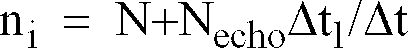
- If, for each individual integration window, N is the number of background electrons and Necho is the total number of electrons of the received signal, then the number ni of the electrons integrated in the i-th window is equal to:


- By solving the above equations, the following is obtained:

- It is evident that, for calculation of Δt1 according to the present technique, it is sufficient to use just two integration windows ni and ni+1 only in the case where the number of background electrons N is zero or, in any case, very small as compared to the number of signal electrons. In general, for N other than zero (as occurs when the technique is applied in illuminated internal or external environments), the use is required of at least one third integration window (nk), which enables the error of calculation of the distance to be reduced significantly.
- The integration window for the acquisition of the background can also be temporally out of phase with respect to the preceding one in such a way as not to collect the echo radiation coming from obstacles set in the range of distance of interest and as to collect only the radiation corresponding to the background. In this sense, whereas each sequence corresponding to the window for collecting the echo signal must necessarily be temporally out of phase with respect to the preceding one by a time interval equal to the duration of the window itself, the sequence corresponding to the window for collecting the background signal can be out of phase by a greater amount.
- The distance d of the object is:

- The formula for the measurement of the distance contains the ratio between the number of electrons integrated in the windows of interest: the result is therefore already independent of the reflectivity of the object, and only depends upon the distance thereof from the receiver. The error on the individual quantities nj depends upon various factors: shot noise, dark noise, reset noise, etc. In the case of the invention, just the shot noise of the signal is taken into account, which, in conditions of normal light intensity, is the dominant contribution. The error on each quantity nj will be:

- If the error on the formula for obtaining Δt1 is propagated under Gaussian hypotheses, the error σd on the measurement of the distance is obtained:

- If the fact that ni+1+ni - 2N is the number of integrated electrons generated just by the transmitted signal is taken into account, it is found that:

- Acquisition of the various quantities nk takes place by serial integration of the signal in the individual windows for a large number of times. The symbol of approximation depends upon the fact that some factors of delay, such as for example the read times, have been neglected.
- Of course, without prejudice to the principle of the invention, the details of implementation and the embodiments may vary widely with respect to what is described and illustrated herein purely by way of example, without thereby departing from the scope of the present invention.
Claims (18)
- A three-dimensional vision system, comprising:- a transmission module, which includes a radiation source;- a receiver module, which comprises at least one photosensitive element, operating in the same spectral window as the transmission module, for detecting the radiation reflected by an obstacle which receives the radiation emitted by the transmission module; and- control and processing electronic means associated to the receiver module;said system being characterized in that the transmission module is constituted by a pulsed source, which, for each three-dimensional recording, emits N = m x n pulses of duration Δt, with repetition frequency equal to f = dc/Δt (dc being the duty cycle of the source signal);
and in that the aforesaid control and processing electronic means comprise processing-synchronization means capable of carrying out:a) integration of the echo pulse train in n sequences of integration windows of duration Δtf, each sequence, which is constituted by m windows with a repetition frequency f, being temporally out of phase with respect to the preceding one by a time duration equal to Δtf, and the phase difference between the first window of the first sequence and the rising edge of the first transmitted pulse being equal to σ; andb) calculation of the distance covered carried out by weighing the levels of the integrated signals for the various sequences and on the basis of the extrapolation of the time of flight of the pulse (equal to the distance in time between the instant of emission and the rising edge of the echo pulse), the integrated-signal level in each sequence depending upon the percentage of pulse that is integrated in the sequence, said value depending upon the instant of arrival of the pulse. - The three-dimensional vision system according to Claim 1, in which the phase difference σ between the first window of the first sequence and the rising edge of the first transmitted pulse is equal to the time of flight of a pulse reflected by an object at the minimum distance.
- The three-dimensional vision system according to Claim 1, in which the duration of the pulse Δt is equal to:

- The three-dimensional vision system according to Claim 1, in which the transmitter is based upon a single laser or a laser array.
- The three-dimensional vision system according to Claim 1, in which the transmitter emits radiation in the near infrared (0.7 to 1.1 µm) .
- The three-dimensional vision system according to Claim 1, in which the receiver is a CCD sensor array.
- The three-dimensional vision system according to Claim 1, in which the receiver is a CMOS sensor array.
- The three-dimensional vision system according to Claim 1, in which the transmitter is scanned either mechanically or electronically.
- The three-dimensional vision system according to Claim 1, in which the receiver is a single sensor and is scanned either mechanically or electro-optically.
- The three-dimensional vision system according to Claim 1, in which zmax = 15 m and zmin = 0, n = 3, m = 1500, dc = 0.1%, and Δt = 50 ns.
- The three-dimensional vision system according to Claim 1, in which zmax = 30 m and zmin = 0, n = 3, m = 1500, dc = 0.1%, and Δt = 100 ns.
- The three-dimensional vision system according to Claim 1, in which zmax = 30 m and zmin = 0, n = 5, m = 900, dc = 0.1%, and Δt = 50 ns.
- The three-dimensional vision system according to Claim 1, in which the integration windows are obtained with an electro-optical modulator.
- The three-dimensional vision system according to Claim 1, in which the integration windows are obtained with an electro-mechanical modulator.
- The three-dimensional vision system according to Claim 1, characterized in that the time interval Δtf is equal to Δt.
- The three-dimensional vision system according to Claim 1, characterized in that n is greater than or equal to 3 in order to enable evaluation of the number of background electrons N.
- The three-dimensional vision system according to Claim 1, characterized in that n is equal to 2, and the system for measurements of distance is used in applications characterized by a very low number of background electrons N, for example at night.
- The three-dimensional vision system according to Claim 1, characterized in that n is equal to 2, and the measurement of the number of background electrons N is carried out by using a third sequence of integration windows, which is temporally out of phase with respect to the preceding one by a time interval greater than Δtf.
Priority Applications (4)
| Application Number | Priority Date | Filing Date | Title |
|---|---|---|---|
| EP03006049A EP1460453B1 (en) | 2003-03-19 | 2003-03-19 | Three-dimension vision system |
| DE60313429T DE60313429T2 (en) | 2003-03-19 | 2003-03-19 | Three-dimensional imaging system |
| AT03006049T ATE360827T1 (en) | 2003-03-19 | 2003-03-19 | THREE-DIMENSIONAL IMAGE PRODUCTION SYSTEM |
| ES03006049T ES2285000T3 (en) | 2003-03-19 | 2003-03-19 | THREE-DIMENSIONAL VISION SYSTEM. |
Applications Claiming Priority (1)
| Application Number | Priority Date | Filing Date | Title |
|---|---|---|---|
| EP03006049A EP1460453B1 (en) | 2003-03-19 | 2003-03-19 | Three-dimension vision system |
Publications (2)
| Publication Number | Publication Date |
|---|---|
| EP1460453A1 true EP1460453A1 (en) | 2004-09-22 |
| EP1460453B1 EP1460453B1 (en) | 2007-04-25 |
Family
ID=32798823
Family Applications (1)
| Application Number | Title | Priority Date | Filing Date |
|---|---|---|---|
| EP03006049A Expired - Lifetime EP1460453B1 (en) | 2003-03-19 | 2003-03-19 | Three-dimension vision system |
Country Status (4)
| Country | Link |
|---|---|
| EP (1) | EP1460453B1 (en) |
| AT (1) | ATE360827T1 (en) |
| DE (1) | DE60313429T2 (en) |
| ES (1) | ES2285000T3 (en) |
Cited By (25)
| Publication number | Priority date | Publication date | Assignee | Title |
|---|---|---|---|---|
| WO2007104124A1 (en) * | 2006-03-15 | 2007-09-20 | Lmi Technologies Limited | Time of flight teat location system |
| WO2009093965A1 (en) * | 2008-01-22 | 2009-07-30 | Delaval Holding Ab | Arrangement and method for determining positions of the teats of a milking animal |
| US8393296B2 (en) | 2011-04-28 | 2013-03-12 | Technologies Holdings Corp. | Milking box with robotic attacher including rotatable gripping portion and nozzle |
| US8590488B2 (en) | 2010-08-31 | 2013-11-26 | Technologies Holdings Corp. | Vision system for facilitating the automated application of disinfectant to the teats of dairy livestock |
| US8671885B2 (en) | 2011-04-28 | 2014-03-18 | Technologies Holdings Corp. | Vision system for robotic attacher |
| US8683946B2 (en) | 2011-04-28 | 2014-04-01 | Technologies Holdings Corp. | System and method of attaching cups to a dairy animal |
| US8746176B2 (en) | 2011-04-28 | 2014-06-10 | Technologies Holdings Corp. | System and method of attaching a cup to a dairy animal according to a sequence |
| US8800487B2 (en) | 2010-08-31 | 2014-08-12 | Technologies Holdings Corp. | System and method for controlling the position of a robot carriage based on the position of a milking stall of an adjacent rotary milking platform |
| US8885891B2 (en) | 2011-04-28 | 2014-11-11 | Technologies Holdings Corp. | System and method for analyzing data captured by a three-dimensional camera |
| US8903129B2 (en) | 2011-04-28 | 2014-12-02 | Technologies Holdings Corp. | System and method for filtering data captured by a 2D camera |
| US9043988B2 (en) | 2011-04-28 | 2015-06-02 | Technologies Holdings Corp. | Milking box with storage area for teat cups |
| US9049843B2 (en) | 2011-04-28 | 2015-06-09 | Technologies Holdings Corp. | Milking box with a robotic attacher having a three-dimensional range of motion |
| US9058657B2 (en) | 2011-04-28 | 2015-06-16 | Technologies Holdings Corp. | System and method for filtering data captured by a 3D camera |
| US9107379B2 (en) | 2011-04-28 | 2015-08-18 | Technologies Holdings Corp. | Arrangement of milking box stalls |
| US9149018B2 (en) | 2010-08-31 | 2015-10-06 | Technologies Holdings Corp. | System and method for determining whether to operate a robot in conjunction with a rotary milking platform based on detection of a milking claw |
| US9161512B2 (en) | 2011-04-28 | 2015-10-20 | Technologies Holdings Corp. | Milking box with robotic attacher comprising an arm that pivots, rotates, and grips |
| US9161511B2 (en) | 2010-07-06 | 2015-10-20 | Technologies Holdings Corp. | Automated rotary milking system |
| US9215861B2 (en) | 2011-04-28 | 2015-12-22 | Technologies Holdings Corp. | Milking box with robotic attacher and backplane for tracking movements of a dairy animal |
| US9258975B2 (en) | 2011-04-28 | 2016-02-16 | Technologies Holdings Corp. | Milking box with robotic attacher and vision system |
| US9265227B2 (en) | 2011-04-28 | 2016-02-23 | Technologies Holdings Corp. | System and method for improved attachment of a cup to a dairy animal |
| US9357744B2 (en) | 2011-04-28 | 2016-06-07 | Technologies Holdings Corp. | Cleaning system for a milking box stall |
| US9681634B2 (en) | 2011-04-28 | 2017-06-20 | Technologies Holdings Corp. | System and method to determine a teat position using edge detection in rear images of a livestock from two cameras |
| US10111401B2 (en) | 2010-08-31 | 2018-10-30 | Technologies Holdings Corp. | System and method for determining whether to operate a robot in conjunction with a rotary parlor |
| US10127446B2 (en) | 2011-04-28 | 2018-11-13 | Technologies Holdings Corp. | System and method for filtering data captured by a 2D camera |
| US10357015B2 (en) | 2011-04-28 | 2019-07-23 | Technologies Holdings Corp. | Robotic arm with double grabber and method of operation |
Families Citing this family (1)
| Publication number | Priority date | Publication date | Assignee | Title |
|---|---|---|---|---|
| US20080273760A1 (en) * | 2007-05-04 | 2008-11-06 | Leonard Metcalfe | Method and apparatus for livestock assessment |
Citations (2)
| Publication number | Priority date | Publication date | Assignee | Title |
|---|---|---|---|---|
| US5835204A (en) * | 1995-12-18 | 1998-11-10 | State Of Israel/Ministry Of Defense | Laser ranging system |
| WO2003016944A2 (en) * | 2001-08-06 | 2003-02-27 | Siemens Aktiengesellschaft | Method and device for recording a three-dimensional distance-measuring image |
-
2003
- 2003-03-19 AT AT03006049T patent/ATE360827T1/en not_active IP Right Cessation
- 2003-03-19 ES ES03006049T patent/ES2285000T3/en not_active Expired - Lifetime
- 2003-03-19 EP EP03006049A patent/EP1460453B1/en not_active Expired - Lifetime
- 2003-03-19 DE DE60313429T patent/DE60313429T2/en not_active Expired - Lifetime
Patent Citations (2)
| Publication number | Priority date | Publication date | Assignee | Title |
|---|---|---|---|---|
| US5835204A (en) * | 1995-12-18 | 1998-11-10 | State Of Israel/Ministry Of Defense | Laser ranging system |
| WO2003016944A2 (en) * | 2001-08-06 | 2003-02-27 | Siemens Aktiengesellschaft | Method and device for recording a three-dimensional distance-measuring image |
Non-Patent Citations (1)
| Title |
|---|
| PELLEGRINI S ET AL: "LASER-BASED DISTANCE MEASUREMENT USING PICOSECOND RESOLUTION TIME-CORRELATED SINGLE-PHOTON COUNTING", MEASUREMENT SCIENCE AND TECHNOLOGY, IOP PUBLISHING, BRISTOL, GB, vol. 11, no. 6, June 2000 (2000-06-01), pages 712 - 716, XP001073125, ISSN: 0957-0233 * |
Cited By (111)
| Publication number | Priority date | Publication date | Assignee | Title |
|---|---|---|---|---|
| EP1996010A4 (en) * | 2006-03-15 | 2014-10-08 | Gea Farm Technologies Gmbh | Time of flight teat location system |
| WO2007104124A1 (en) * | 2006-03-15 | 2007-09-20 | Lmi Technologies Limited | Time of flight teat location system |
| WO2009093965A1 (en) * | 2008-01-22 | 2009-07-30 | Delaval Holding Ab | Arrangement and method for determining positions of the teats of a milking animal |
| US8624744B2 (en) | 2008-01-22 | 2014-01-07 | Delaval Holding Ab | Arrangement and method for determining positions of the teats of a milking animal |
| US9161511B2 (en) | 2010-07-06 | 2015-10-20 | Technologies Holdings Corp. | Automated rotary milking system |
| US9480238B2 (en) | 2010-08-31 | 2016-11-01 | Technologies Holdings Corp. | Vision system for facilitating the automated application of disinfectant to the teats of dairy livestock |
| US9433184B2 (en) | 2010-08-31 | 2016-09-06 | Technologies Holdings Corp. | Automated system for applying disinfectant to the teats of dairy livestock |
| US10595501B2 (en) | 2010-08-31 | 2020-03-24 | Technologies Holdings Corp. | Automated system for applying disinfectant to the teats of dairy livestock |
| US8707905B2 (en) | 2010-08-31 | 2014-04-29 | Technologies Holdings Corp. | Automated system for applying disinfectant to the teats of dairy livestock |
| US8720382B2 (en) | 2010-08-31 | 2014-05-13 | Technologies Holdings Corp. | Vision system for facilitating the automated application of disinfectant to the teats of dairy livestock |
| US8720383B2 (en) | 2010-08-31 | 2014-05-13 | Technologies Holdings Corp. | Vision system for facilitating the automated application of disinfectant to the teats of dairy livestock |
| US8726843B2 (en) | 2010-08-31 | 2014-05-20 | Technologies Holdings Corp. | Automated system for applying disinfectant to the teats of dairy livestock |
| US10595500B2 (en) | 2010-08-31 | 2020-03-24 | Technologies Holdings Corp. | Automated system for applying disinfectant to the teats of dairy livestock |
| US8800487B2 (en) | 2010-08-31 | 2014-08-12 | Technologies Holdings Corp. | System and method for controlling the position of a robot carriage based on the position of a milking stall of an adjacent rotary milking platform |
| US8807086B2 (en) | 2010-08-31 | 2014-08-19 | Technologies Holdings Corp | Automated system for applying disinfectant to the teats of dairy livestock |
| US8807085B2 (en) | 2010-08-31 | 2014-08-19 | Technologies Holdings Corp. | Automated system for applying disinfectant to the teats of dairy livestock |
| US10327414B2 (en) | 2010-08-31 | 2019-06-25 | Technologies Holdings Corp. | System and method for controlling the position of a robot carriage based on the position of a milking stall of an adjacent rotary milking platform |
| US10111401B2 (en) | 2010-08-31 | 2018-10-30 | Technologies Holdings Corp. | System and method for determining whether to operate a robot in conjunction with a rotary parlor |
| US9980458B2 (en) | 2010-08-31 | 2018-05-29 | Technologies Holdings Corp. | System and method for controlling the position of a robot carriage based on the position of a milking stall of an adjacent rotary milking platform |
| US9894876B2 (en) | 2010-08-31 | 2018-02-20 | Technologies Holdings Corp. | Automated system for applying disinfectant to the teats of dairy livestock |
| US9888664B2 (en) | 2010-08-31 | 2018-02-13 | Technologies Holdings Corp. | Automated system for applying disinfectant to the teats of dairy livestock |
| US9775325B2 (en) | 2010-08-31 | 2017-10-03 | Technologies Holdings Corp. | Automated system for applying disinfectant to the teats of dairy livestock |
| US9763424B1 (en) | 2010-08-31 | 2017-09-19 | Technologies Holdings Corp. | Vision system for facilitating the automated application of disinfectant to the teats of dairy livestock |
| US9737043B2 (en) | 2010-08-31 | 2017-08-22 | Technologies Holdings Corp. | Automated system for applying disinfectant to the teats of dairy livestock |
| US9706747B2 (en) | 2010-08-31 | 2017-07-18 | Technologies Holdings Corp. | Automated system for applying disinfectant to the teats of dairy livestock |
| US9686962B2 (en) | 2010-08-31 | 2017-06-27 | Technologies Holdings Corp. | Vision system for facilitating the automated application of disinfectant to the teats of dairy livestock |
| US9126335B2 (en) | 2010-08-31 | 2015-09-08 | Technologies Holdings Corp. | Automated system for applying disinfectant to the teats of dairy livestock |
| US9149018B2 (en) | 2010-08-31 | 2015-10-06 | Technologies Holdings Corp. | System and method for determining whether to operate a robot in conjunction with a rotary milking platform based on detection of a milking claw |
| US9686961B2 (en) | 2010-08-31 | 2017-06-27 | Technologies Holdings Corp. | Automated system for moving a robotic arm along a rotary milking platform |
| US8590488B2 (en) | 2010-08-31 | 2013-11-26 | Technologies Holdings Corp. | Vision system for facilitating the automated application of disinfectant to the teats of dairy livestock |
| US9648839B2 (en) | 2010-08-31 | 2017-05-16 | Technologies Holdings Corp. | System and method for determining whether to operate a robot in conjunction with a rotary milking platform based on detection of a milking claw |
| US9648843B2 (en) | 2010-08-31 | 2017-05-16 | Technologies Holdings Corp. | Automated system for applying disinfectant to the teats of dairy livestock |
| US9560832B2 (en) | 2010-08-31 | 2017-02-07 | Technologies Holdings Corp. | Automated system for applying disinfectant to the teats of dairy livestock |
| US9247709B2 (en) | 2010-08-31 | 2016-02-02 | Technologies Holdings Corp. | System and method for controlling the position of a robot carriage based on the position of a milking stall of an adjacent rotary milking platform |
| US9549531B2 (en) | 2010-08-31 | 2017-01-24 | Technologies Holdings Corp. | Automated system for applying disinfectant to the teats of dairy livestock |
| US9516854B2 (en) | 2010-08-31 | 2016-12-13 | Technologies Holdings Corp. | Vision system for facilitating the automated application of disinfectant to the teats of dairy livestock |
| US10477828B2 (en) | 2010-08-31 | 2019-11-19 | Technologies Holdings Corp. | Automated system for applying disinfectant to the teats of dairy livestock |
| US9474248B2 (en) | 2010-08-31 | 2016-10-25 | Technologies Holdings Corp. | Automated system for applying disinfectant to the teats of dairy livestock |
| US9462781B2 (en) | 2010-08-31 | 2016-10-11 | Technologies Holdings Corp. | Automated system for moving a robotic arm along a rotary milking platform |
| US9462782B2 (en) | 2010-08-31 | 2016-10-11 | Technologies Holdings Corp. | System and method for controlling the position of a robot carriage based on the position of a milking stall of an adjacent rotary milking platform |
| US9439392B2 (en) | 2010-08-31 | 2016-09-13 | Technologies Holdings Corp. | Automated system for applying disinfectant to the teats of dairy livestock |
| US9043988B2 (en) | 2011-04-28 | 2015-06-02 | Technologies Holdings Corp. | Milking box with storage area for teat cups |
| US9706745B2 (en) | 2011-04-28 | 2017-07-18 | Technologies Holdings Corp. | Vision system for robotic attacher |
| US9374979B2 (en) | 2011-04-28 | 2016-06-28 | Technologies Holdings Corp. | Milking box with backplane and robotic attacher |
| US9374975B2 (en) | 2011-04-28 | 2016-06-28 | Technologies Holdings Corp. | System and method of attaching cups to a dairy animal |
| US9402365B2 (en) | 2011-04-28 | 2016-08-02 | Technologies Holdings Corp. | Milking box with robotic attacher |
| US9357744B2 (en) | 2011-04-28 | 2016-06-07 | Technologies Holdings Corp. | Cleaning system for a milking box stall |
| US9326480B2 (en) | 2011-04-28 | 2016-05-03 | Technologies Holdings Corp. | Milking box with robotic attacher |
| US9439390B2 (en) | 2011-04-28 | 2016-09-13 | Technologies Holdings Corp. | System and method of attaching cups to a dairy animal |
| US9282720B2 (en) | 2011-04-28 | 2016-03-15 | Technologies Holdings Corp. | Arrangement of milking box stalls |
| US9282718B2 (en) | 2011-04-28 | 2016-03-15 | Technologies Holdings Corp. | Milking box with robotic attacher |
| US9462780B2 (en) | 2011-04-28 | 2016-10-11 | Technologies Holdings Corp. | Vision system for robotic attacher |
| US9468188B2 (en) | 2011-04-28 | 2016-10-18 | Technologies Holdings Corp. | System and method of attaching cups to a dairy animal |
| US9271471B2 (en) | 2011-04-28 | 2016-03-01 | Technologies Holdings Corp. | System and method for analyzing data captured by a three-dimensional camera |
| US8393296B2 (en) | 2011-04-28 | 2013-03-12 | Technologies Holdings Corp. | Milking box with robotic attacher including rotatable gripping portion and nozzle |
| US9480236B2 (en) | 2011-04-28 | 2016-11-01 | Technologies Holdings Corp. | System and method of attaching a cup to a dairy animal according to a sequence |
| US9485955B2 (en) | 2011-04-28 | 2016-11-08 | Technologies Holdings Corp. | System and method of attaching cups to a dairy animal |
| US8671885B2 (en) | 2011-04-28 | 2014-03-18 | Technologies Holdings Corp. | Vision system for robotic attacher |
| US9265227B2 (en) | 2011-04-28 | 2016-02-23 | Technologies Holdings Corp. | System and method for improved attachment of a cup to a dairy animal |
| US9183623B2 (en) | 2011-04-28 | 2015-11-10 | Technologies Holdings Corp. | System and method for filtering data captured by a 3D camera |
| US9258975B2 (en) | 2011-04-28 | 2016-02-16 | Technologies Holdings Corp. | Milking box with robotic attacher and vision system |
| US9253959B2 (en) | 2011-04-28 | 2016-02-09 | Technologies Holdings Corp. | System and method of attaching cups to a dairy animal |
| US9549529B2 (en) | 2011-04-28 | 2017-01-24 | Technologies Holdings Corp. | Robotic attacher and method of operation |
| US9215861B2 (en) | 2011-04-28 | 2015-12-22 | Technologies Holdings Corp. | Milking box with robotic attacher and backplane for tracking movements of a dairy animal |
| US9582871B2 (en) | 2011-04-28 | 2017-02-28 | Technologies Holdings Corp. | System and method for filtering data captured by a 3D camera |
| US9615537B2 (en) | 2011-04-28 | 2017-04-11 | Technologies Holdings Corp. | Milking box with backplane responsive robotic attacher |
| US9648841B2 (en) | 2011-04-28 | 2017-05-16 | Technologies Holdings Corp. | Cleaning system for a milking box stall |
| US9510554B2 (en) | 2011-04-28 | 2016-12-06 | Technologies Holdings Corp. | System and method for improved attachment of a cup to a dairy animal |
| US9171208B2 (en) | 2011-04-28 | 2015-10-27 | Technologies Holdings Corp. | System and method for filtering data captured by a 2D camera |
| US9681634B2 (en) | 2011-04-28 | 2017-06-20 | Technologies Holdings Corp. | System and method to determine a teat position using edge detection in rear images of a livestock from two cameras |
| US9681635B2 (en) | 2011-04-28 | 2017-06-20 | Technologies Holdings Corp. | Milking box with robotic attacher |
| US9161512B2 (en) | 2011-04-28 | 2015-10-20 | Technologies Holdings Corp. | Milking box with robotic attacher comprising an arm that pivots, rotates, and grips |
| US9107378B2 (en) | 2011-04-28 | 2015-08-18 | Technologies Holdings Corp. | Milking box with robotic attacher |
| US9686959B2 (en) | 2011-04-28 | 2017-06-27 | Technologies Holdings Corp. | Milking box with robotic attacher |
| US9686960B2 (en) | 2011-04-28 | 2017-06-27 | Technologies Holdings Corp. | Milking box with robotic attacher |
| US9107379B2 (en) | 2011-04-28 | 2015-08-18 | Technologies Holdings Corp. | Arrangement of milking box stalls |
| US9374974B2 (en) | 2011-04-28 | 2016-06-28 | Technologies Holdings Corp. | Milking box with robotic attacher |
| US9737039B2 (en) | 2011-04-28 | 2017-08-22 | Technologies Holdings Corp. | Robotic attacher and method of operation |
| US9737040B2 (en) | 2011-04-28 | 2017-08-22 | Technologies Holdings Corp. | System and method for analyzing data captured by a three-dimensional camera |
| US9737041B2 (en) | 2011-04-28 | 2017-08-22 | Technologies Holdings Corp. | System and method of attaching cups to a dairy animal |
| US9737042B2 (en) | 2011-04-28 | 2017-08-22 | Technologies Holdings Corp. | System and method of attaching cups to a dairy animal |
| US9058657B2 (en) | 2011-04-28 | 2015-06-16 | Technologies Holdings Corp. | System and method for filtering data captured by a 3D camera |
| US9737048B2 (en) | 2011-04-28 | 2017-08-22 | Technologies Holdings Corp. | Arrangement of milking box stalls |
| US9743635B2 (en) | 2011-04-28 | 2017-08-29 | Technologies Holdings Corp. | System and method of attaching cups to a dairy animal |
| US9756830B2 (en) | 2011-04-28 | 2017-09-12 | Technologies Holdings Corp. | Milking box with robotic attacher |
| US9049843B2 (en) | 2011-04-28 | 2015-06-09 | Technologies Holdings Corp. | Milking box with a robotic attacher having a three-dimensional range of motion |
| US9763422B2 (en) | 2011-04-28 | 2017-09-19 | Technologies Holdings Corp. | Milking box with robotic attacher |
| US9491924B2 (en) | 2011-04-28 | 2016-11-15 | Technologies Holdings Corp. | Milking box with robotic attacher comprising an arm that pivots, rotates, and grips |
| US9883654B2 (en) | 2011-04-28 | 2018-02-06 | Technologies Holdings Corp. | Arrangement of milking box stalls |
| US8903129B2 (en) | 2011-04-28 | 2014-12-02 | Technologies Holdings Corp. | System and method for filtering data captured by a 2D camera |
| US8885891B2 (en) | 2011-04-28 | 2014-11-11 | Technologies Holdings Corp. | System and method for analyzing data captured by a three-dimensional camera |
| US9901067B2 (en) | 2011-04-28 | 2018-02-27 | Technologies Holdings Corp. | Robotic attacher and method of operation |
| US9980460B2 (en) | 2011-04-28 | 2018-05-29 | Technologies Holdings Corp. | System and method for improved attachment of a cup to a dairy animal |
| US9980459B2 (en) | 2011-04-28 | 2018-05-29 | Technologies Holdings Corp. | Milking box with robotic attacher comprising an arm that pivots, rotates, and grips |
| US8651051B2 (en) | 2011-04-28 | 2014-02-18 | Technologies Holdings Corp. | Milking box with robotic attacher |
| US8826858B2 (en) | 2011-04-28 | 2014-09-09 | Technologies Holdings Corp. | Milking box with robotic attacher |
| US10127446B2 (en) | 2011-04-28 | 2018-11-13 | Technologies Holdings Corp. | System and method for filtering data captured by a 2D camera |
| US10143179B2 (en) | 2011-04-28 | 2018-12-04 | Technologies Holdings Corp. | Milking box with a robotic attacher having a three-dimensional range of motion |
| US10172320B2 (en) | 2011-04-28 | 2019-01-08 | Technologies Holdings Corp. | System and method of attaching a cup to a dairy animal according to a sequence |
| US10303939B2 (en) | 2011-04-28 | 2019-05-28 | Technologies Holdings Corp. | System and method for filtering data captured by a 2D camera |
| US10327415B2 (en) | 2011-04-28 | 2019-06-25 | Technologies Holdings Corp. | System and method for improved attachment of a cup to a dairy animal |
| US8813680B2 (en) | 2011-04-28 | 2014-08-26 | Technologies Holdings Corp. | Milking box with robotic attacher |
| US10349618B2 (en) | 2011-04-28 | 2019-07-16 | Technologies Holdings Corp. | System and method of attaching a cup to a dairy animal according to a sequence |
| US10357015B2 (en) | 2011-04-28 | 2019-07-23 | Technologies Holdings Corp. | Robotic arm with double grabber and method of operation |
| US10373306B2 (en) | 2011-04-28 | 2019-08-06 | Technologies Holdings Corp. | System and method for filtering data captured by a 3D camera |
| US9504224B2 (en) | 2011-04-28 | 2016-11-29 | Technologies Holdings Corp. | Milking box with robotic attacher |
| US10477826B2 (en) | 2011-04-28 | 2019-11-19 | Technologies Holdings Corp. | Milking box with robotic attacher |
| US8746176B2 (en) | 2011-04-28 | 2014-06-10 | Technologies Holdings Corp. | System and method of attaching a cup to a dairy animal according to a sequence |
| US8683946B2 (en) | 2011-04-28 | 2014-04-01 | Technologies Holdings Corp. | System and method of attaching cups to a dairy animal |
| US10602712B2 (en) | 2011-04-28 | 2020-03-31 | Technologies Holdings Corp. | Milking box with storage area for teat cups |
| US11096370B2 (en) | 2011-04-28 | 2021-08-24 | Technologies Holdings Corp. | Milking box with robotic attacher comprising an arm that pivots, rotates, and grips |
Also Published As
| Publication number | Publication date |
|---|---|
| ATE360827T1 (en) | 2007-05-15 |
| EP1460453B1 (en) | 2007-04-25 |
| DE60313429T2 (en) | 2008-01-03 |
| DE60313429D1 (en) | 2007-06-06 |
| ES2285000T3 (en) | 2007-11-16 |
Similar Documents
| Publication | Publication Date | Title |
|---|---|---|
| EP1460453A1 (en) | Three-dimension vision system | |
| US7212278B2 (en) | Method and device for recording a three-dimensional distance-measuring image | |
| US6753950B2 (en) | Optical distance measurement | |
| US7554652B1 (en) | Light-integrating rangefinding device and method | |
| JP3976868B2 (en) | Optical sensor using light transmission time | |
| KR100508277B1 (en) | Method and device for recording three-dimensional distance-measuring images | |
| US5118180A (en) | Method and apparatus for determining the range of vision of a motor vehicle driver upon encountering fog or other obstacle | |
| US10613223B2 (en) | Method of detecting objects, corresponding system and apparatus | |
| EP2017651B2 (en) | Reference pixel array with varying sensitivities for TOF sensor | |
| US7952690B2 (en) | Method and system for acquiring a 3-D image of a scene | |
| TWI432768B (en) | Procedure and device to determining a distance by means of an opto-electronic image sensor | |
| KR100462418B1 (en) | Sensor for detecting clocks and wet areas | |
| CN103064087B (en) | Three-dimensional imaging radar system and method based on multiple integral | |
| EP2260325B1 (en) | Light-integrating rangefinding device and method | |
| CN110456369B (en) | Flight time sensing system and distance measuring method thereof | |
| CN110673152A (en) | Time-of-flight sensor and distance measuring method thereof | |
| JP3621817B2 (en) | Optical pulse radar device and optical pulse light receiving device | |
| US8098712B2 (en) | Optical correlation apparatus and method | |
| US20180017678A1 (en) | Power efficient lidar | |
| US7301136B2 (en) | Method for operating a photoelectric sensor arrangement with inverting and shifting a received signal and corresponding sensor | |
| JP3044146B2 (en) | Distance measuring device | |
| RU2059973C1 (en) | Single-pulse radar method | |
| Bykov et al. | Signals modeling in laser distance measurements | |
| ITTO20010904A1 (en) | THREE-DIMENSIONAL VISION SYSTEM. |
Legal Events
| Date | Code | Title | Description |
|---|---|---|---|
| PUAI | Public reference made under article 153(3) epc to a published international application that has entered the european phase |
Free format text: ORIGINAL CODE: 0009012 |
|
| AK | Designated contracting states |
Kind code of ref document: A1 Designated state(s): AT BE BG CH CY CZ DE DK EE ES FI FR GB GR HU IE IT LI LU MC NL PT RO SE SI SK TR |
|
| AX | Request for extension of the european patent |
Extension state: AL LT LV MK |
|
| 17P | Request for examination filed |
Effective date: 20040916 |
|
| 17Q | First examination report despatched |
Effective date: 20050113 |
|
| AKX | Designation fees paid |
Designated state(s): AT BE BG CH CY CZ DE DK EE ES FI FR GB GR HU IE IT LI LU MC NL PT RO SE SI SK TR |
|
| GRAP | Despatch of communication of intention to grant a patent |
Free format text: ORIGINAL CODE: EPIDOSNIGR1 |
|
| GRAS | Grant fee paid |
Free format text: ORIGINAL CODE: EPIDOSNIGR3 |
|
| GRAA | (expected) grant |
Free format text: ORIGINAL CODE: 0009210 |
|
| AK | Designated contracting states |
Kind code of ref document: B1 Designated state(s): AT BE BG CH CY CZ DE DK EE ES FI FR GB GR HU IE IT LI LU MC NL PT RO SE SI SK TR |
|
| PG25 | Lapsed in a contracting state [announced via postgrant information from national office to epo] |
Ref country code: CH Free format text: LAPSE BECAUSE OF FAILURE TO SUBMIT A TRANSLATION OF THE DESCRIPTION OR TO PAY THE FEE WITHIN THE PRESCRIBED TIME-LIMIT Effective date: 20070425 Ref country code: FI Free format text: LAPSE BECAUSE OF FAILURE TO SUBMIT A TRANSLATION OF THE DESCRIPTION OR TO PAY THE FEE WITHIN THE PRESCRIBED TIME-LIMIT Effective date: 20070425 Ref country code: LI Free format text: LAPSE BECAUSE OF FAILURE TO SUBMIT A TRANSLATION OF THE DESCRIPTION OR TO PAY THE FEE WITHIN THE PRESCRIBED TIME-LIMIT Effective date: 20070425 |
|
| REG | Reference to a national code |
Ref country code: GB Ref legal event code: FG4D |
|
| REG | Reference to a national code |
Ref country code: IE Ref legal event code: FG4D |
|
| REG | Reference to a national code |
Ref country code: CH Ref legal event code: EP |
|
| REF | Corresponds to: |
Ref document number: 60313429 Country of ref document: DE Date of ref document: 20070606 Kind code of ref document: P |
|
| REG | Reference to a national code |
Ref country code: SE Ref legal event code: TRGR |
|
| ET | Fr: translation filed | ||
| PG25 | Lapsed in a contracting state [announced via postgrant information from national office to epo] |
Ref country code: PT Free format text: LAPSE BECAUSE OF FAILURE TO SUBMIT A TRANSLATION OF THE DESCRIPTION OR TO PAY THE FEE WITHIN THE PRESCRIBED TIME-LIMIT Effective date: 20070925 |
|
| REG | Reference to a national code |
Ref country code: CH Ref legal event code: PL |
|
| NLV1 | Nl: lapsed or annulled due to failure to fulfill the requirements of art. 29p and 29m of the patents act | ||
| REG | Reference to a national code |
Ref country code: ES Ref legal event code: FG2A Ref document number: 2285000 Country of ref document: ES Kind code of ref document: T3 |
|
| PG25 | Lapsed in a contracting state [announced via postgrant information from national office to epo] |
Ref country code: AT Free format text: LAPSE BECAUSE OF FAILURE TO SUBMIT A TRANSLATION OF THE DESCRIPTION OR TO PAY THE FEE WITHIN THE PRESCRIBED TIME-LIMIT Effective date: 20070425 |
|
| PG25 | Lapsed in a contracting state [announced via postgrant information from national office to epo] |
Ref country code: BE Free format text: LAPSE BECAUSE OF FAILURE TO SUBMIT A TRANSLATION OF THE DESCRIPTION OR TO PAY THE FEE WITHIN THE PRESCRIBED TIME-LIMIT Effective date: 20070425 |
|
| PG25 | Lapsed in a contracting state [announced via postgrant information from national office to epo] |
Ref country code: NL Free format text: LAPSE BECAUSE OF FAILURE TO SUBMIT A TRANSLATION OF THE DESCRIPTION OR TO PAY THE FEE WITHIN THE PRESCRIBED TIME-LIMIT Effective date: 20070425 Ref country code: DK Free format text: LAPSE BECAUSE OF FAILURE TO SUBMIT A TRANSLATION OF THE DESCRIPTION OR TO PAY THE FEE WITHIN THE PRESCRIBED TIME-LIMIT Effective date: 20070425 Ref country code: BG Free format text: LAPSE BECAUSE OF FAILURE TO SUBMIT A TRANSLATION OF THE DESCRIPTION OR TO PAY THE FEE WITHIN THE PRESCRIBED TIME-LIMIT Effective date: 20070725 Ref country code: CZ Free format text: LAPSE BECAUSE OF FAILURE TO SUBMIT A TRANSLATION OF THE DESCRIPTION OR TO PAY THE FEE WITHIN THE PRESCRIBED TIME-LIMIT Effective date: 20070425 Ref country code: SI Free format text: LAPSE BECAUSE OF FAILURE TO SUBMIT A TRANSLATION OF THE DESCRIPTION OR TO PAY THE FEE WITHIN THE PRESCRIBED TIME-LIMIT Effective date: 20070425 |
|
| PG25 | Lapsed in a contracting state [announced via postgrant information from national office to epo] |
Ref country code: SK Free format text: LAPSE BECAUSE OF FAILURE TO SUBMIT A TRANSLATION OF THE DESCRIPTION OR TO PAY THE FEE WITHIN THE PRESCRIBED TIME-LIMIT Effective date: 20070425 |
|
| PLBE | No opposition filed within time limit |
Free format text: ORIGINAL CODE: 0009261 |
|
| STAA | Information on the status of an ep patent application or granted ep patent |
Free format text: STATUS: NO OPPOSITION FILED WITHIN TIME LIMIT |
|
| 26N | No opposition filed |
Effective date: 20080128 |
|
| PG25 | Lapsed in a contracting state [announced via postgrant information from national office to epo] |
Ref country code: GR Free format text: LAPSE BECAUSE OF FAILURE TO SUBMIT A TRANSLATION OF THE DESCRIPTION OR TO PAY THE FEE WITHIN THE PRESCRIBED TIME-LIMIT Effective date: 20070726 |
|
| PG25 | Lapsed in a contracting state [announced via postgrant information from national office to epo] |
Ref country code: RO Free format text: LAPSE BECAUSE OF FAILURE TO SUBMIT A TRANSLATION OF THE DESCRIPTION OR TO PAY THE FEE WITHIN THE PRESCRIBED TIME-LIMIT Effective date: 20070425 |
|
| PGFP | Annual fee paid to national office [announced via postgrant information from national office to epo] |
Ref country code: SE Payment date: 20080306 Year of fee payment: 6 |
|
| PGFP | Annual fee paid to national office [announced via postgrant information from national office to epo] |
Ref country code: ES Payment date: 20080418 Year of fee payment: 6 |
|
| PG25 | Lapsed in a contracting state [announced via postgrant information from national office to epo] |
Ref country code: MC Free format text: LAPSE BECAUSE OF NON-PAYMENT OF DUE FEES Effective date: 20080331 |
|
| PG25 | Lapsed in a contracting state [announced via postgrant information from national office to epo] |
Ref country code: IE Free format text: LAPSE BECAUSE OF NON-PAYMENT OF DUE FEES Effective date: 20080319 Ref country code: EE Free format text: LAPSE BECAUSE OF FAILURE TO SUBMIT A TRANSLATION OF THE DESCRIPTION OR TO PAY THE FEE WITHIN THE PRESCRIBED TIME-LIMIT Effective date: 20070425 |
|
| PG25 | Lapsed in a contracting state [announced via postgrant information from national office to epo] |
Ref country code: CY Free format text: LAPSE BECAUSE OF FAILURE TO SUBMIT A TRANSLATION OF THE DESCRIPTION OR TO PAY THE FEE WITHIN THE PRESCRIBED TIME-LIMIT Effective date: 20070425 |
|
| EUG | Se: european patent has lapsed | ||
| REG | Reference to a national code |
Ref country code: ES Ref legal event code: FD2A Effective date: 20090320 |
|
| PG25 | Lapsed in a contracting state [announced via postgrant information from national office to epo] |
Ref country code: HU Free format text: LAPSE BECAUSE OF FAILURE TO SUBMIT A TRANSLATION OF THE DESCRIPTION OR TO PAY THE FEE WITHIN THE PRESCRIBED TIME-LIMIT Effective date: 20071026 Ref country code: ES Free format text: LAPSE BECAUSE OF NON-PAYMENT OF DUE FEES Effective date: 20090320 Ref country code: LU Free format text: LAPSE BECAUSE OF NON-PAYMENT OF DUE FEES Effective date: 20080319 |
|
| PG25 | Lapsed in a contracting state [announced via postgrant information from national office to epo] |
Ref country code: TR Free format text: LAPSE BECAUSE OF FAILURE TO SUBMIT A TRANSLATION OF THE DESCRIPTION OR TO PAY THE FEE WITHIN THE PRESCRIBED TIME-LIMIT Effective date: 20070425 |
|
| PG25 | Lapsed in a contracting state [announced via postgrant information from national office to epo] |
Ref country code: SE Free format text: LAPSE BECAUSE OF NON-PAYMENT OF DUE FEES Effective date: 20090320 |
|
| PGFP | Annual fee paid to national office [announced via postgrant information from national office to epo] |
Ref country code: GB Payment date: 20110316 Year of fee payment: 9 |
|
| PGFP | Annual fee paid to national office [announced via postgrant information from national office to epo] |
Ref country code: FR Payment date: 20120319 Year of fee payment: 10 |
|
| PGFP | Annual fee paid to national office [announced via postgrant information from national office to epo] |
Ref country code: IT Payment date: 20120305 Year of fee payment: 10 |
|
| PGFP | Annual fee paid to national office [announced via postgrant information from national office to epo] |
Ref country code: DE Payment date: 20120411 Year of fee payment: 10 |
|
| GBPC | Gb: european patent ceased through non-payment of renewal fee |
Effective date: 20120319 |
|
| PG25 | Lapsed in a contracting state [announced via postgrant information from national office to epo] |
Ref country code: GB Free format text: LAPSE BECAUSE OF NON-PAYMENT OF DUE FEES Effective date: 20120319 |
|
| REG | Reference to a national code |
Ref country code: FR Ref legal event code: ST Effective date: 20131129 |
|
| REG | Reference to a national code |
Ref country code: DE Ref legal event code: R119 Ref document number: 60313429 Country of ref document: DE Effective date: 20131001 |
|
| PG25 | Lapsed in a contracting state [announced via postgrant information from national office to epo] |
Ref country code: DE Free format text: LAPSE BECAUSE OF NON-PAYMENT OF DUE FEES Effective date: 20131001 Ref country code: FR Free format text: LAPSE BECAUSE OF NON-PAYMENT OF DUE FEES Effective date: 20130402 |
|
| PG25 | Lapsed in a contracting state [announced via postgrant information from national office to epo] |
Ref country code: IT Free format text: LAPSE BECAUSE OF NON-PAYMENT OF DUE FEES Effective date: 20130319 |