JP3976868B2 - Optical sensor using light transmission time - Google Patents
Optical sensor using light transmission time Download PDFInfo
- Publication number
- JP3976868B2 JP3976868B2 JP00848498A JP848498A JP3976868B2 JP 3976868 B2 JP3976868 B2 JP 3976868B2 JP 00848498 A JP00848498 A JP 00848498A JP 848498 A JP848498 A JP 848498A JP 3976868 B2 JP3976868 B2 JP 3976868B2
- Authority
- JP
- Japan
- Prior art keywords
- signal
- optical sensor
- optical
- correlation function
- kkf
- Prior art date
- Legal status (The legal status is an assumption and is not a legal conclusion. Google has not performed a legal analysis and makes no representation as to the accuracy of the status listed.)
- Expired - Fee Related
Links
- 230000003287 optical effect Effects 0.000 title claims description 101
- 230000005540 biological transmission Effects 0.000 title description 18
- 238000005314 correlation function Methods 0.000 claims description 62
- 238000005259 measurement Methods 0.000 claims description 27
- 238000011156 evaluation Methods 0.000 claims description 4
- 238000012544 monitoring process Methods 0.000 claims 1
- 230000002596 correlated effect Effects 0.000 description 6
- 230000000875 corresponding effect Effects 0.000 description 5
- 238000010586 diagram Methods 0.000 description 5
- 230000003111 delayed effect Effects 0.000 description 3
- 238000001514 detection method Methods 0.000 description 2
- 230000001174 ascending effect Effects 0.000 description 1
- 230000007423 decrease Effects 0.000 description 1
- 238000000034 method Methods 0.000 description 1
Images
Classifications
-
- G—PHYSICS
- G01—MEASURING; TESTING
- G01S—RADIO DIRECTION-FINDING; RADIO NAVIGATION; DETERMINING DISTANCE OR VELOCITY BY USE OF RADIO WAVES; LOCATING OR PRESENCE-DETECTING BY USE OF THE REFLECTION OR RERADIATION OF RADIO WAVES; ANALOGOUS ARRANGEMENTS USING OTHER WAVES
- G01S17/00—Systems using the reflection or reradiation of electromagnetic waves other than radio waves, e.g. lidar systems
- G01S17/02—Systems using the reflection of electromagnetic waves other than radio waves
- G01S17/06—Systems determining position data of a target
- G01S17/08—Systems determining position data of a target for measuring distance only
- G01S17/32—Systems determining position data of a target for measuring distance only using transmission of continuous waves, whether amplitude-, frequency-, or phase-modulated, or unmodulated
-
- G—PHYSICS
- G01—MEASURING; TESTING
- G01S—RADIO DIRECTION-FINDING; RADIO NAVIGATION; DETERMINING DISTANCE OR VELOCITY BY USE OF RADIO WAVES; LOCATING OR PRESENCE-DETECTING BY USE OF THE REFLECTION OR RERADIATION OF RADIO WAVES; ANALOGOUS ARRANGEMENTS USING OTHER WAVES
- G01S17/00—Systems using the reflection or reradiation of electromagnetic waves other than radio waves, e.g. lidar systems
- G01S17/02—Systems using the reflection of electromagnetic waves other than radio waves
- G01S17/06—Systems determining position data of a target
- G01S17/08—Systems determining position data of a target for measuring distance only
-
- G—PHYSICS
- G01—MEASURING; TESTING
- G01S—RADIO DIRECTION-FINDING; RADIO NAVIGATION; DETERMINING DISTANCE OR VELOCITY BY USE OF RADIO WAVES; LOCATING OR PRESENCE-DETECTING BY USE OF THE REFLECTION OR RERADIATION OF RADIO WAVES; ANALOGOUS ARRANGEMENTS USING OTHER WAVES
- G01S17/00—Systems using the reflection or reradiation of electromagnetic waves other than radio waves, e.g. lidar systems
- G01S17/87—Combinations of systems using electromagnetic waves other than radio waves
Landscapes
- Physics & Mathematics (AREA)
- Electromagnetism (AREA)
- Engineering & Computer Science (AREA)
- Computer Networks & Wireless Communication (AREA)
- General Physics & Mathematics (AREA)
- Radar, Positioning & Navigation (AREA)
- Remote Sensing (AREA)
- Optical Radar Systems And Details Thereof (AREA)
- Length Measuring Devices By Optical Means (AREA)
- Measurement Of Optical Distance (AREA)
- Radar Systems Or Details Thereof (AREA)
Description
【0001】
【発明の属する技術分野】
本発明は光センサに関し、特にモニター領域に光信号を送信する光送信器と、モニター領域にある対象物で反射された光信号を受信する光受信器からなり、光信号を送信してから受信するまでの経過時間を観測して光センサと対象物との間の距離を得る光伝達時間計測の原理に基づく光センサに関する。
【0002】
【従来の技術】
上記の光伝達時間計測の原理に基づく光センサに加えて、光送信器と光受信器を互いに並べ光送信ビームと光受信ビームの間の角度を決定し、この角度から光センサと対象物との間の距離を得る三角測量の原理に基づくセンサがある。この三角測量法では対象物の傾きによって角度の誤差が生じ、結果的に誤った距離が得られる欠点がある。さらに検出距離を長くしても低い精度しか得られない。この不都合を補うには、光送信光学系と光受信光学系との間隔を大きくとらなくてはならないため、光センサを非常に大きくしなければならない。しかし光送信光学系と光受信光学系との間隔を大きくとることは、光センサの非常に近くにある対象物を検知できない点で不利である。
【0003】
上記の理由から、光伝達時間計測の原理に基づく光センサは前述の不都合を有せず基本的に優れている。しかし、これらの光伝達時間計測の原理に基づく光センサでは光伝達時間を決定するために複雑な信号処理が必要なため、技術的に複雑でありコストも相対的に高い。さらに、送信信号または参照信号と受信信号との相関から光伝達時間を計算するこのような光伝達時間センサでは、測定が正確な領域が小さいというのも欠点である。
【0004】
【発明が解決しようとする課題】
本発明の目的は、安価で簡単に製作でき、正確に計測できる領域を可能な限り大きくした光伝達時間計測の原理に基づく光センサを提供することにある。
【0005】
【課題を解決するための手段】
本発明の目的は光センサであって、モニター領域に光信号Tx,Txdを送信する光送信器と、モニター領域にある対象物から反射された光信号Rxを受信する光受信器と、光送信器に送る第1信号Txおよび第1信号と明確な位相関係を有し第1信号と異なった信号形状を有する第2信号L0を生成する少なくとも1つの信号発生器と、受信光信号Rxと第2信号L0,L0dとの相関関数KKFを生成する相関手段と、相関手段の後に光センサと対象物との距離を決定する評価手段と、を有する光センサにより達成される。
【0006】
最初に述べた相関原理に基づく光伝達時間センサと異なり、本発明では、送信光信号と第2信号を同時に、あるいは既知の相対的時間シフトを有するように生成して受信信号と第2信号との相関関数をとっている。送信光信号と受信光信号は第2信号と異なる信号形状を有し、結果的に相関関数が非線形形状となるように信号形状を選ぶことができる。この非線形性は用いる信号形状を選ぶことにより選択でき、関心のある計測距離外の相関関数の値を上側または下側閾値よりそれぞれ大きくまたは小さくすることができ、関心のある計測距離内の相関関数の形状を上側および下側閾値内で比較的急峻にすることができる。この関心のある計測距離内での急峻な相関関数形状によって、本発明では非常に高精度な光センサが得られ、特に、たとえば6mの距離では1乃至2cmの精度で決定できる。
【0007】
関心のある計測距離外で、相関関数が上側または下側閾値よりそれぞれ大きくまたは小さくなっていても、本発明の光センサでは不正確さの点で何ら問題はない。この種の不正確さの問題は、関心のある計測距離外の相関関数の値が上側および下側閾値内にあるときにだけ生じるが、前述の2つの信号形状を適当に選べば問題とならない。
【0008】
本発明において光送信器に送られる第1信号、および相関関数を生成するために用いる第2信号は互いに同じ周期を有することが望ましい。
この第1信号および第2信号の信号形状を、相関関数が1周期に1つの、この1周期内に生じる他の強度変化よりも大きくまたは急峻な強度変化を有するように選ぶことが望ましい。この1つの強度変化は走査距離を評価・決定するために用いる相関関数の領域に正確に対応している。強度変化が急峻なことで計測距離を非常に正確に決定できる。
【0009】
本発明の光センサは、特に簡単には、この2つの信号がそれぞれ互いに異なる振幅の強度ステップを有するとき、すなわちこの2つの信号が矩形パルスからなり互いに異なる時間間隔で起こる場合に実現される。
この点から各信号は同じ長さの連続的な個々の信号から組立てられ、個々の信号が第1、または第2信号の振幅を有していることが望ましい。したがって個々の信号の長さは、たとえば光センサに組み込まれたクロック発生器の周期に対応している。
【0010】
この2つの信号の振幅がゼロに関して対称に配置されることが望ましい。この場合2つの信号は2極性であり、相関関数の対称線または相関関数を生成する相関器の出力電圧が値ゼロをとることができる利点がある。したがって対称線は所定の受信レベルに依存しない利点がある。
さらに、前述の相関関数の強度変化が急峻で、その一時的な範囲が相関をとる2つの信号を形成する個々の信号の長さ以下であれば有利である。この種の急峻さによって計測距離を高精度で測定できる。
【0011】
コンピュータ支援によって、相関をとる2つの信号に用いられるそれぞれの信号形状が見つけられ、信号はたとえば乱数発生器によって生成された後に相関がとられ、またこのようにして形成された相関関数が分析されることが望ましい。ランダムに見つけられた信号は相関関数が特定の基準を満たす場合、特に上記のような強度変化を有する場合に有用であると判断される。
【0012】
相関関数の値が強度変化の前では上側閾値より大きく、強度変化の後では下側閾値より小さいのが好都合である。同様に、相関関数の値が強度変化の前では下側閾値より小さく、強度変化の後では上側閾値より大きくてもよい。前述のように相関関数の対称線は上側および下側閾値のおよそ中央にあるのが望ましい。
本発明による相関関数の非線形性を得るには、相関をとる2つの信号はその形状が異なっている。特に2つの信号が1周期内で周期の50%以上において非常に異なっているのが適当である。
【0013】
特に本発明の好適な実施例は、所望の様々な計測距離に光センサが対応できるように相関関数の強度変化の位置を1周期内の任意の位置にシフトできることにある。この種の強度変化のシフト、または相関関数の変化は用いる信号形状の変更や、相関をとる2つの信号の時間シフトを与える遅延時間の設定によって得ることができる。
【0014】
この目的のためには、光送信器に送る遅延信号を生成するための可変遅延装置を、第1信号を生成する信号発生器と光送信器との間に備えるのが望ましい。これと同様に、またはこれに加えて、遅延第2信号を生成するための可変遅延装置を、第2信号を生成する信号発生器と相関器との間に備えてもよい。
遅延時間の設定または相関関数の強度変化のシフトは、たとえば光センサに備えた指示キー(teach key)や光センサに接続したパソコン(PC)によって生じさせることができる。このように本発明の光センサは簡便に、所望の様々な計測距離に対応が可能である。
【0015】
さらに望ましい実施態様について特許請求の範囲に記載してある。本発明について実施例および図面を参照して以下に説明する。
【0016】
【発明の実施の形態】
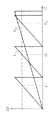
図1は本出願人内部の従来技術による光センサの相互相関関数K1,K2を示し、同じ信号形状を有する送信信号と受信信号の相互相関関数が形成されている。相互相関関数K1は短い周期で比較的急峻な特性を有し、相互相関関数K2は長い周期で緩い傾斜を有している。相互相関関数K1の周期が短いことは、3つの上昇領域のどの領域で実際の測定値があるのかを直接決定できないため、正確さの点において不利である。相互相関関数K1の測定値から2つの相関信号に3つのシフトdT1,dT2,dT3が存在する。
【0017】
相互相関関数K2の形状については、比較的緩やかな傾斜のため2つの相関関数の検出シフト、すなわち計測距離の精度が低く不利である。
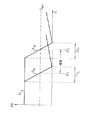
図2は本発明による、2つの選択的に調節可能な非線形相互相関関数K3の形状を示している。これらの形状で典型的なのは相互相関関数が初期の領域では実質的に一定形状であり、比較的急峻な下り傾斜が起きることである。この相互相関関数の下り傾斜の後で実質的に一定の小さな値となるか、または図2に示すように緩やかに上昇する。計測距離の決定値dTは相互相関関数K3がどの値で対称線Ssymと交差するかで決められる。
【0018】
K3aの形状の場合では相互相関関数の決定下り傾斜(determining decline)は領域B1で生じている。値dT1に対応する計測距離は光センサおよび相互相関関数により、計測対象物がdT1に対応する距離だけ前方あるいは後方に位置しているかを決定でき、B1の範囲に対応する距離のどこに計測対象物があるかを正確に決定することができる。
【0019】
本発明によれば、これと異なる光センサの決定計測距離を設定したければ、相関関数の特性を前述したように、たとえばK3bの形状になるようにシフトさせればよい。それによって範囲B2にある計測対象物の正確な位置を決定することができる。
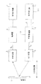
図3は本発明による光センサの回路のブロック図を示す。
【0020】
信号発生器1にはクロックCLKが送られ、互いに異なる2つの信号Tx,L0を発生する。これらの信号は遅延装置2に送られ、信号Txまたは信号L0、あるいはその両者が遅延される。遅延信号Txdは遅延装置2を通り、対象物4の方向に光信号を送信する光送信装置3に送られる。したがって光信号の強度変化または形状は信号Txdの信号形状に対応する。
【0021】
対象物4は光送信装置3から送信された光を光受信装置5に向けて反射し、光受信装置5は受信光を電気信号Rxに変換し、その信号形状は受信光の強度変化または形状に対応する。
信号Rxは相関器6に送られ、遅延信号L0dと作用する。
相関器6内では、2つの信号RxとL0dの相互相関関数がとられ、信号評価装置7に供給される。
【0022】
図3における光センサは、遅延装置2によって信号TxまたはL0の遅延を設定することで光センサと対象物4との間隔が異なっても適用できる。
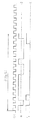
図4は、図3の信号発生器1に作用すし、周期的に繰り返す一連の矩形パルスからなるクロック信号CLKの形状を示す。
クロック信号CLKの下には図3の信号発生器1で生成された信号L0を示しており、ゼロに対して対称な振幅の強度ステップである。信号L0の周期T(L0)は信号CLKの15クロックサイクルに対応する。
【0023】
同様に、信号L0の下には図3の信号発生器1で生成された信号Txを示しており2つの強度、すなわち0と1を有している。信号Txの周期T(Tx)は信号CLKの15クロックサイクルに対応する。実際では信号CLKの15クロックサイクル以上、特に数100クロックサイクルの周期の信号L0,Txを用いることも十分に考えられる。
【0024】
標準化された強度値で示した1周期内の2つの信号L0,Txの強度形状は以下のように表すことができる。
L0 1 -1 1 1 1 1 1 -1 -1 1 -1 -1 -1 -1 1
Tx 1 0 1 0 0 0 0 0 0 0 0 0 0 1 1
上記の2つの信号の相互相関関数(KKF)は標準化した形で以下のように表すことができる。
KKF 2 2 2 2 4 2 2 2 -2 -2 -2 -2 -2 -2 -2
上記の相互相関関数の決定強度変化は値が2から−2に変化するステップの所で生じている。相互相関関数は15クロックサイクルの周期を有しているので、光センサの明確な計測範囲も15クロックサイクルに対応している。
【0025】
この場合での理想的な状況は、2つの信号L0,Txの形状を相互相関関数のステップが値4から−4に変化する所で生じるように選ぶことである。そのとき強度変化の標準化レベルは8である。しかし実際強度変化が最大値の半分、すなわちこの場合のように4であれば十分である。
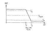
図5は、図4の信号処理によって得られた相互相関関数の形状を模式的に示している。相関をとった2つの信号は相互相関関数を形成する相関器で乗算され、その後の信号評価のためローパスフィルタにかけられる。
【0026】
図5に示す形状は、強度変化がクロックサイクルT2-T1で起きており、相互相関関数の強度がこのステップ以前において閾値SO以上であり、強度変化以後では閾値SU以下であることを示している。
したがって、ある特定の受信信号に対して相互相関関数の値が閾値SO以上にあると決定されれば対象物は前方、すなわち設定計測距離よりも前にあり、相互相関関数の値が閾値SU以下にあれば対象物は後方、すなわち設定計測距離の後ろにあることを意味している。
【0027】
もし相互相関関数の値が図5に示すSsymの値、望ましくはゼロに対応すると決定されれば、対象物は正確に設定計測距離にあるか、または対象物は全く存在しない。この不明確さは付加的なチェックにより取り除くことができ、たとえば並行して受信信号を調べることがこの目的に適う。つまり、もし受信信号強度が所定の閾値以下であれば対象物は存在せず、閾値以上であれば対象物は正確に設定計測距離にある。
【0028】
相互相関関数の値がSUとSOの間にあると決定されれば、対応する範囲において相互相関関数が急峻であることから、対象物と光センサの距離を非常に正確に測定できる。
【図面の簡単な説明】
【図1】従来の光センサの相関関数の形状を示す図である。
【図2】本発明による光センサの相関関数の形状を示す図である。
【図3】本発明による光センサの回路配置を説明するブロック図である。
【図4】本発明による光センサの相関関数を形成するために用いられる、光送信器に送られる第1信号Txおよび第2信号LOの形状を時間に関して示した図である。
【図5】本発明による光センサの相関関数の形状の他の例を示す図である。
【符号の説明】
1 信号発生器
2 可変遅延器
3 光送信器
4 対象物
5 光受信器
6 相関器
7 信号評価器[0001]
BACKGROUND OF THE INVENTION
The present invention relates to an optical sensor, and more particularly to an optical transmitter that transmits an optical signal to a monitor area and an optical receiver that receives an optical signal reflected by an object in the monitor area. The present invention relates to an optical sensor based on the principle of optical transmission time measurement for observing the elapsed time to obtain the distance between the optical sensor and an object.
[0002]
[Prior art]
In addition to the above-described optical sensor based on the principle of optical transmission time measurement, the optical transmitter and the optical receiver are aligned with each other to determine the angle between the optical transmission beam and the optical reception beam, and from this angle the optical sensor and the object There are sensors based on the principle of triangulation to get the distance between. This triangulation method has a drawback that an angle error occurs due to the inclination of the object, resulting in an incorrect distance. Furthermore, even if the detection distance is increased, only low accuracy can be obtained. In order to compensate for this inconvenience, the distance between the optical transmission optical system and the optical reception optical system must be large, and thus the optical sensor must be very large. However, increasing the distance between the optical transmission optical system and the optical reception optical system is disadvantageous in that an object located very close to the optical sensor cannot be detected.
[0003]
For the above reasons, the optical sensor based on the principle of measuring the light transmission time is basically excellent without the above-mentioned disadvantages. However, these optical sensors based on the principle of optical transmission time measurement require complicated signal processing in order to determine the optical transmission time, so that they are technically complex and relatively expensive. Furthermore, in such an optical transmission time sensor that calculates the optical transmission time from the correlation between the transmission signal or the reference signal and the reception signal, it is also a drawback that the area where the measurement is accurate is small.
[0004]
[Problems to be solved by the invention]
An object of the present invention is to provide an optical sensor based on the principle of optical transmission time measurement that can be manufactured inexpensively and easily and has an area that can be accurately measured as large as possible.
[0005]
[Means for Solving the Problems]
An object of the present invention is an optical sensor, an optical transmitter for transmitting optical signals T x and T xd to a monitor region, and an optical receiver for receiving an optical signal R x reflected from an object in the monitor region; at least one signal generator for generating a second signal L 0 having a first signal a different signal shape having a definite phase relationship with the first signal T x and the first signal to be sent to the optical transmitter, receiver achieved by a light sensor having a correlation means for generating a correlation function KKF the optical signal of R x and second signals L 0, L 0d, and a evaluation means for determining the distance between the optical sensor and the object after the correlation means Is done.
[0006]
Unlike the optical transmission time sensor based on the correlation principle described at the beginning, in the present invention, the transmission optical signal and the second signal are generated simultaneously or with a known relative time shift, and the received signal and the second signal are generated. The correlation function is taken. The transmitted optical signal and the received optical signal have signal shapes different from those of the second signal, and as a result, the signal shape can be selected so that the correlation function becomes a nonlinear shape. This non-linearity can be selected by choosing the signal shape to be used, the value of the correlation function outside the measurement distance of interest can be made larger or smaller than the upper or lower threshold, respectively, and the correlation function within the measurement distance of interest Can be relatively steep within the upper and lower thresholds. Due to the steep correlation function shape within the measurement distance of interest, the present invention provides a very high precision optical sensor, which can be determined with an accuracy of 1 to 2 cm, particularly at a distance of 6 m.
[0007]
Even if the correlation function is larger or smaller than the upper or lower threshold value outside the measurement distance of interest, the optical sensor of the present invention has no problem in terms of inaccuracy. This type of inaccuracy problem occurs only when the value of the correlation function outside the measurement distance of interest is within the upper and lower thresholds, but it does not matter if the above two signal shapes are chosen appropriately. .
[0008]
In the present invention, it is desirable that the first signal sent to the optical transmitter and the second signal used for generating the correlation function have the same period.
It is desirable to select the signal shapes of the first signal and the second signal so that the correlation function has one intensity change that is greater or steeper than other intensity changes that occur within this period. This one intensity change corresponds exactly to the region of the correlation function used to evaluate and determine the scanning distance. The measurement distance can be determined very accurately because the intensity change is steep.
[0009]
The optical sensor according to the invention is realized in a particularly simple manner when the two signals have intensity steps with different amplitudes, i.e. when the two signals consist of rectangular pulses and occur at different time intervals.
From this point, it is desirable that each signal be assembled from successive individual signals of the same length, with each signal having the amplitude of the first or second signal. Thus, the length of each signal corresponds to, for example, the period of a clock generator built into the photosensor.
[0010]
It is desirable that the amplitudes of the two signals are arranged symmetrically with respect to zero. In this case, the two signals are bipolar, and there is an advantage that the output voltage of the correlator generating the correlation function or the correlation function can take a value of zero. Therefore, the symmetry line has an advantage that it does not depend on a predetermined reception level.
Furthermore, it is advantageous if the intensity change of the correlation function described above is steep and its temporary range is less than or equal to the length of the individual signals forming two correlated signals. This kind of steepness makes it possible to measure the measurement distance with high accuracy.
[0011]
With the aid of a computer, the respective signal shapes used for the two signals to be correlated are found, the signals are correlated after being generated, for example by a random number generator, and the correlation function thus formed is analyzed. It is desirable. A signal found at random is judged to be useful when the correlation function satisfies a specific criterion, in particular, when it has an intensity change as described above.
[0012]
Conveniently, the value of the correlation function is greater than the upper threshold before the intensity change and less than the lower threshold after the intensity change. Similarly, the value of the correlation function may be smaller than the lower threshold before the intensity change and larger than the upper threshold after the intensity change. As mentioned above, the symmetry line of the correlation function is preferably at approximately the center of the upper and lower thresholds.
In order to obtain the nonlinearity of the correlation function according to the present invention, the two signals to be correlated have different shapes. In particular, it is appropriate that the two signals are very different within one period over 50% of the period.
[0013]
In particular, the preferred embodiment of the present invention is that the position of the intensity change of the correlation function can be shifted to an arbitrary position within one period so that the optical sensor can cope with various desired measurement distances. This type of intensity change shift or correlation function change can be obtained by changing the signal shape to be used or setting a delay time that gives a time shift between two correlated signals.
[0014]
For this purpose, it is desirable to provide a variable delay device for generating a delay signal to be sent to the optical transmitter between the signal generator for generating the first signal and the optical transmitter. Similarly or in addition, a variable delay device for generating the delayed second signal may be provided between the signal generator for generating the second signal and the correlator.
The setting of the delay time or the shift of the intensity change of the correlation function can be caused by, for example, an instruction key provided in the optical sensor or a personal computer (PC) connected to the optical sensor. Thus, the optical sensor of the present invention can easily cope with various desired measurement distances.
[0015]
Further preferred embodiments are described in the claims. The present invention will be described below with reference to examples and drawings.
[0016]
DETAILED DESCRIPTION OF THE INVENTION
FIG. 1 shows cross-correlation functions K 1 and K 2 of an optical sensor according to the prior art inside the applicant, and a cross-correlation function between a transmission signal and a reception signal having the same signal shape is formed. The cross-correlation function K 1 has a relatively steep characteristic with a short period, and the cross-correlation function K 2 has a gentle slope with a long period. The short period of the cross-correlation function K 1 is disadvantageous in terms of accuracy because it is not possible to directly determine in which of the three ascending regions the actual measurement value is present. There are three shifts dT 1 , dT 2 , dT 3 in the two correlation signals from the measured value of the cross-correlation function K 1 .
[0017]
The shape of the cross-correlation function K 2 is disadvantageous because the detection shift of the two correlation functions, that is, the accuracy of the measurement distance is low because of the relatively gentle slope.
FIG. 2 shows the shapes of two selectively adjustable nonlinear cross-correlation functions K 3 according to the present invention. Typical of these shapes is that the cross-correlation function is substantially constant in the initial region, and a relatively steep downward slope occurs. After the downward slope of the cross-correlation function, it becomes a substantially constant small value, or rises gently as shown in FIG. The determination value dT of the measurement distance is determined by what value the cross-correlation function K 3 intersects with the symmetry line S sym .
[0018]
In the case of the shape of K 3a, the determining decline of the cross-correlation function occurs in region B 1 . The measurement distance corresponding to the value dT 1 can be determined by the optical sensor and the cross-correlation function to determine whether the measurement object is located forward or backward by the distance corresponding to dT 1 , and where in the distance corresponding to the range of B 1 It is possible to accurately determine whether there is a measurement object.
[0019]
According to the present invention, if it is desired to set a different measurement distance for the optical sensor, the characteristic of the correlation function may be shifted to a shape of, for example, K 3b as described above. Thereby, an accurate position of the measurement object in the range B 2 can be determined.
FIG. 3 shows a block diagram of the circuit of the optical sensor according to the present invention.
[0020]
A clock CLK is sent to the signal generator 1, and two different signals T x and L 0 are generated. These signals are sent to a delay device 2, the signal T x or signals L 0, or both is delayed. The delay signal T xd passes through the delay device 2 and is sent to the optical transmission device 3 that transmits an optical signal in the direction of the object 4. Therefore, the intensity change or shape of the optical signal corresponds to the signal shape of the signal T xd .
[0021]
The object 4 reflects the light transmitted from the optical transmission device 3 toward the optical reception device 5, and the optical reception device 5 converts the received light into an electric signal R x , and the signal shape is a change in intensity of the received light or Corresponds to the shape.
The signal Rx is sent to the correlator 6 and acts on the delayed signal L0d .
In the correlator 6, a cross-correlation function between the two signals R x and L 0d is taken and supplied to the signal evaluation device 7.
[0022]
The optical sensor in FIG. 3 can be applied even if the distance between the optical sensor and the object 4 is different by setting the delay of the signal T x or L 0 by the delay device 2.
FIG. 4 shows the shape of the clock signal CLK consisting of a series of rectangular pulses that act on the signal generator 1 of FIG. 3 and repeat periodically.
Below the clock signal CLK, the signal L 0 generated by the signal generator 1 of FIG. 3 is shown, which is an intensity step with amplitude symmetrical to zero. Period T (L 0) of the signal L 0 is corresponding to 15 clock cycles of the signal CLK.
[0023]
Similarly, below the signal L 0 , the signal T x generated by the signal generator 1 of FIG. 3 is shown and has two intensities, namely 0 and 1. Signal period T (T x) of T x corresponds to the 15 clock cycle of signal CLK. In practice, it is sufficiently conceivable to use the signals L 0 and T x having a period of 15 clock cycles or more, in particular several hundred clock cycles of the signal CLK.
[0024]
The intensity shapes of the two signals L 0 and T x in one cycle indicated by the standardized intensity value can be expressed as follows.
L 0 1 -1 1 1 1 1 1 -1 -1 1 -1 -1 -1 -1 1
T x 1 0 1 0 0 0 0 0 0 0 0 0 0 1 1
The cross-correlation function (KKF) of the above two signals can be expressed in standardized form as follows:
KKF 2 2 2 2 4 2 2 2 -2 -2 -2 -2 -2 -2 -2
The above change in the strength of the cross correlation function occurs at the step where the value changes from 2 to -2. Since the cross-correlation function has a period of 15 clock cycles, the clear measurement range of the photosensor also corresponds to 15 clock cycles.
[0025]
The ideal situation in this case is to choose the shapes of the two signals L 0 and T x so that they occur where the cross-correlation function step changes from a value of 4 to -4. At that time, the standardization level of intensity change is 8. However, it is sufficient if the actual intensity change is half of the maximum value, ie 4 as in this case.
FIG. 5 schematically shows the shape of the cross-correlation function obtained by the signal processing of FIG. The two correlated signals are multiplied by a correlator forming a cross-correlation function and then subjected to a low pass filter for subsequent signal evaluation.
[0026]
Shape shown in Figure 5 occurs at an intensity variation clock cycle T 2 -T 1, the intensity of the cross-correlation function is the threshold value S O above in this step before it the intensity variation since it is below the threshold S U Is shown.
Therefore, if it is determined that the value of the cross-correlation function is greater than or equal to the threshold value S O for a specific received signal, the object is ahead, that is, before the set measurement distance, and the value of the cross-correlation function is the threshold value S If it is below U , it means that the object is behind, that is, behind the set measurement distance.
[0027]
If it is determined that the value of the cross-correlation function corresponds to the value of S sym shown in FIG. 5, preferably zero, the object is exactly at the set measurement distance or there is no object at all. This ambiguity can be removed by additional checks, for example, examining the received signal in parallel serves this purpose. That is, if the received signal strength is equal to or less than a predetermined threshold, the object does not exist.
[0028]
If it is determined that the value of the cross-correlation function is between S U and S O , the cross-correlation function is steep in the corresponding range, so that the distance between the object and the photosensor can be measured very accurately.
[Brief description of the drawings]
FIG. 1 is a diagram showing the shape of a correlation function of a conventional optical sensor.
FIG. 2 is a diagram showing the shape of a correlation function of the optical sensor according to the present invention.
FIG. 3 is a block diagram illustrating a circuit arrangement of the photosensor according to the present invention.
FIG. 4 shows the shape of the first signal T x and the second signal L O sent to the optical transmitter used for forming the correlation function of the optical sensor according to the invention with respect to time.
FIG. 5 is a diagram showing another example of the shape of the correlation function of the optical sensor according to the present invention.
[Explanation of symbols]
DESCRIPTION OF SYMBOLS 1 Signal generator 2 Variable delay device 3 Optical transmitter 4 Object 5 Optical receiver 6 Correlator 7 Signal evaluator
Claims (8)
前記第1信号 ( T x ) 及び前記第2信号 ( L 0 ) は、前記相関関数 ( KKF ) が1周期内に起きる他の全ての強度変化よりも大きな及び/又は急峻な1つの強度変化を前記1周期内に有するような信号形状を有し、
前記相関関数 ( KKF ) の値が、前記強度変化の前では上側閾値(S O ) より大きく(または下側閾値(S U )より小さく)、前記強度変化の後では下側閾値(S U ) より小さい(または上側閾値(S O )より大きい)ことを特徴とする光センサ。The optical sensor, an optical transmitter for transmitting optical signals to the monitor area and (3), the object in the monitoring area (4) an optical receiver for receiving optical signals reflected from the (5), wherein first signal sent to the optical transmitter (3) (T x) and the first signal (T x) and the first signal having a definite phase relationship (T x) and the second signal having a different signal shapes ( L 0 ) and at least one signal generator (1), and correlation means (6) for generating a correlation function (KKF) between the received optical signal (R x ) and the second signal (L 0 ) And an evaluation means (7) for determining a distance between the optical sensor and the object (4) after the correlation means (6) ,
Said first signal (T x) and the second signal (L 0), the correlation function (KKF) is large and / or abrupt one intensity variation than all other intensity variations that occur in one cycle Having a signal shape as in one cycle,
The value of the correlation function ( KKF ) is larger than the upper threshold value (S O ) before the intensity change (or smaller than the lower threshold value (S U )), and after the intensity change, the lower threshold value (S U ). An optical sensor characterized by being smaller (or larger than the upper threshold ( SO )) .
Applications Claiming Priority (2)
| Application Number | Priority Date | Filing Date | Title |
|---|---|---|---|
| DE19701803A DE19701803A1 (en) | 1997-01-20 | 1997-01-20 | Light sensor with light transit time evaluation |
| DE197018033 | 1997-01-20 |
Publications (2)
| Publication Number | Publication Date |
|---|---|
| JPH10246783A JPH10246783A (en) | 1998-09-14 |
| JP3976868B2 true JP3976868B2 (en) | 2007-09-19 |
Family
ID=7817822
Family Applications (1)
| Application Number | Title | Priority Date | Filing Date |
|---|---|---|---|
| JP00848498A Expired - Fee Related JP3976868B2 (en) | 1997-01-20 | 1998-01-20 | Optical sensor using light transmission time |
Country Status (4)
| Country | Link |
|---|---|
| US (1) | US6100539A (en) |
| EP (1) | EP0854368B1 (en) |
| JP (1) | JP3976868B2 (en) |
| DE (2) | DE19701803A1 (en) |
Families Citing this family (39)
| Publication number | Priority date | Publication date | Assignee | Title |
|---|---|---|---|---|
| US6516286B1 (en) | 1999-04-06 | 2003-02-04 | Leica Geosystems Ag | Method for measuring the distance to at least one target |
| EP1043603A1 (en) * | 1999-04-06 | 2000-10-11 | Leica Geosystems AG | Method for detecting the distance of at least one target |
| DE19926214A1 (en) * | 1999-06-09 | 2001-01-11 | Balluff Gebhard Gmbh & Co | Suppression of noise signals in signal from optical sensor or proximity switch by transmitting chirp sequence and autocorrelating |
| DE19947023A1 (en) * | 1999-09-30 | 2001-05-10 | Siemens Gebaeudesicherheit Gmb | Detecting light-scattering objects, e.g. for intruder alarm |
| DE10106770A1 (en) * | 2001-02-12 | 2002-09-05 | Omron Electronics Mfg Of Germa | Measuring device and method for evaluating the light transit time |
| DE10110420A1 (en) * | 2001-03-05 | 2002-09-12 | Sick Ag | Device for determining a distance profile |
| DE102004031024C5 (en) * | 2004-06-26 | 2011-04-28 | Leuze Lumiflex Gmbh + Co. Kg | Optical sensor |
| WO2008154736A1 (en) * | 2007-06-18 | 2008-12-24 | Leddartech Inc. | Lighting system with driver assistance capabilities |
| US8242476B2 (en) * | 2005-12-19 | 2012-08-14 | Leddartech Inc. | LED object detection system and method combining complete reflection traces from individual narrow field-of-view channels |
| USRE46672E1 (en) | 2006-07-13 | 2018-01-16 | Velodyne Lidar, Inc. | High definition LiDAR system |
| EP2158579B1 (en) * | 2007-06-18 | 2014-10-15 | Leddartech Inc. | Lighting system with traffic management capabilities |
| US7640122B2 (en) * | 2007-11-07 | 2009-12-29 | Institut National D'optique | Digital signal processing in optical systems used for ranging applications |
| EP2232462B1 (en) * | 2007-12-21 | 2015-12-16 | Leddartech Inc. | Parking management system and method using lighting system |
| WO2009079789A1 (en) | 2007-12-21 | 2009-07-02 | Leddartech Inc. | Detection and ranging methods and systems |
| USRE46930E1 (en) * | 2007-12-21 | 2018-07-03 | Leddartech Inc. | Distance detection method and system |
| WO2009121181A1 (en) * | 2008-04-04 | 2009-10-08 | Leddartech Inc. | Optical level measurement device and method |
| CN102959599B (en) | 2009-12-22 | 2015-07-15 | 莱达科技股份有限公司 | Active 3D monitoring system for traffic detection |
| JP5338829B2 (en) * | 2011-03-15 | 2013-11-13 | 株式会社デンソー | Driving assistance device |
| US8908159B2 (en) | 2011-05-11 | 2014-12-09 | Leddartech Inc. | Multiple-field-of-view scannerless optical rangefinder in high ambient background light |
| EP2721593B1 (en) | 2011-06-17 | 2017-04-05 | Leddartech Inc. | System and method for traffic side detection and characterization |
| US9235988B2 (en) | 2012-03-02 | 2016-01-12 | Leddartech Inc. | System and method for multipurpose traffic detection and characterization |
| US9606228B1 (en) | 2014-02-20 | 2017-03-28 | Banner Engineering Corporation | High-precision digital time-of-flight measurement with coarse delay elements |
| WO2016038536A1 (en) | 2014-09-09 | 2016-03-17 | Leddartech Inc. | Discretization of detection zone |
| US10627490B2 (en) | 2016-01-31 | 2020-04-21 | Velodyne Lidar, Inc. | Multiple pulse, LIDAR based 3-D imaging |
| CN109154661A (en) | 2016-03-19 | 2019-01-04 | 威力登激光雷达有限公司 | Integrated irradiation and detection for the 3-D imaging based on LIDAR |
| US10393877B2 (en) | 2016-06-01 | 2019-08-27 | Velodyne Lidar, Inc. | Multiple pixel scanning LIDAR |
| WO2018183843A1 (en) | 2017-03-31 | 2018-10-04 | Velodyne Lidar, Inc. | Integrated lidar illumination power control |
| CN110809704B (en) | 2017-05-08 | 2022-11-01 | 威力登激光雷达美国有限公司 | LIDAR data acquisition and control |
| US11294041B2 (en) | 2017-12-08 | 2022-04-05 | Velodyne Lidar Usa, Inc. | Systems and methods for improving detection of a return signal in a light ranging and detection system |
| US11971507B2 (en) | 2018-08-24 | 2024-04-30 | Velodyne Lidar Usa, Inc. | Systems and methods for mitigating optical crosstalk in a light ranging and detection system |
| US10712434B2 (en) | 2018-09-18 | 2020-07-14 | Velodyne Lidar, Inc. | Multi-channel LIDAR illumination driver |
| US11082010B2 (en) | 2018-11-06 | 2021-08-03 | Velodyne Lidar Usa, Inc. | Systems and methods for TIA base current detection and compensation |
| US12061263B2 (en) | 2019-01-07 | 2024-08-13 | Velodyne Lidar Usa, Inc. | Systems and methods for a configurable sensor system |
| US11885958B2 (en) | 2019-01-07 | 2024-01-30 | Velodyne Lidar Usa, Inc. | Systems and methods for a dual axis resonant scanning mirror |
| US10613203B1 (en) | 2019-07-01 | 2020-04-07 | Velodyne Lidar, Inc. | Interference mitigation for light detection and ranging |
| TWI729742B (en) * | 2020-03-23 | 2021-06-01 | 友達光電股份有限公司 | Display device |
| US11422266B2 (en) | 2020-07-21 | 2022-08-23 | Leddartech Inc. | Beam-steering devices and methods for LIDAR applications |
| WO2022016277A1 (en) | 2020-07-21 | 2022-01-27 | Leddartech Inc. | Systems and methods for wide-angle lidar using non-uniform magnification optics |
| WO2022016276A1 (en) | 2020-07-21 | 2022-01-27 | Leddartech Inc. | Beam-steering device particularly for lidar systems |
Family Cites Families (10)
| Publication number | Priority date | Publication date | Assignee | Title |
|---|---|---|---|---|
| FR2258639A1 (en) * | 1974-01-18 | 1975-08-18 | Thomson Csf | Short distance target detection system - uses pulsed semiconductor laser transmission with correlation in receiver |
| DD250588A1 (en) * | 1986-04-24 | 1987-10-14 | Akad Wissenschaften Ddr | OPTICAL IMPULSE DETECTOR |
| CA2038818A1 (en) * | 1990-03-30 | 1991-10-01 | Akio Nagamune | Distance measuring method and apparatus therefor |
| FR2666903B1 (en) * | 1990-09-18 | 1993-09-24 | Snecma | TELEMETRIC METHOD FOR MEASURING SHORT DISTANCES. |
| US5214268A (en) * | 1991-08-15 | 1993-05-25 | Ncr Corporation | Apparatus for programming a bar code reader |
| US5256865A (en) * | 1991-11-05 | 1993-10-26 | Ncr Corporation | Automatic sensing and programming circuit and programming method for optical scanners |
| DE4217423A1 (en) * | 1992-05-26 | 1994-02-24 | Ifm Electronic Gmbh | Distance measurement, e.g. for industrial mfg. - correlating signals, e.g. from laser diode, passed along measurement path and via digital delay element |
| DE4422886C2 (en) * | 1994-06-30 | 1997-02-20 | Daimler Benz Aerospace Ag | Method and device for the optical determination of spatial positions of individual reflecting objects |
| US5724041A (en) * | 1994-11-24 | 1998-03-03 | The Furukawa Electric Co., Ltd. | Spread spectrum radar device using pseudorandom noise signal for detection of an object |
| DE19517001A1 (en) * | 1995-05-09 | 1996-11-14 | Sick Optik Elektronik Erwin | Method and device for determining the light propagation time over a measuring section arranged between a measuring device and a reflecting object |
-
1997
- 1997-01-20 DE DE19701803A patent/DE19701803A1/en not_active Withdrawn
- 1997-12-04 DE DE59712486T patent/DE59712486D1/en not_active Expired - Lifetime
- 1997-12-04 EP EP97121367A patent/EP0854368B1/en not_active Expired - Lifetime
-
1998
- 1998-01-20 JP JP00848498A patent/JP3976868B2/en not_active Expired - Fee Related
- 1998-01-20 US US09/008,937 patent/US6100539A/en not_active Expired - Lifetime
Also Published As
| Publication number | Publication date |
|---|---|
| EP0854368A2 (en) | 1998-07-22 |
| DE59712486D1 (en) | 2005-12-22 |
| JPH10246783A (en) | 1998-09-14 |
| EP0854368A3 (en) | 1999-09-01 |
| EP0854368B1 (en) | 2005-11-16 |
| DE19701803A1 (en) | 1998-10-01 |
| US6100539A (en) | 2000-08-08 |
Similar Documents
| Publication | Publication Date | Title |
|---|---|---|
| JP3976868B2 (en) | Optical sensor using light transmission time | |
| US7212278B2 (en) | Method and device for recording a three-dimensional distance-measuring image | |
| CN101490579B (en) | Optical distance measuring method and corresponding optical distance measurement device | |
| US5262837A (en) | Laser range finder | |
| CN101349751B (en) | Handheld laser distance measuring device using an impulse back-mixing method | |
| CN103998949B (en) | Improvements to or relating to time-of-flight signal processing | |
| JP5627456B2 (en) | Determination of sine wave period | |
| JP2002533732A (en) | Time delay determination and signal shift determination | |
| RU2000126837A (en) | METHOD AND SYSTEM FOR MEASURING RADAR REFLECTIVE ABILITY AND DOPPLER SHIFT BY MEANS OF A PULSE RADAR | |
| JP2000509485A (en) | Object position detection method | |
| EP0097041B1 (en) | Correlation of noise signals | |
| US5892576A (en) | Process and device for the electro-optical measurement of distance | |
| CN105745556A (en) | Method and device for measuring a relative velocity by means of an acoustic sensor | |
| CN113970744B (en) | Distance measurement method, system and medium based on linear frequency modulation ultrasonic wave | |
| US6831875B2 (en) | Apparatus for ultrasonically detecting position of web edge and method of doing the same | |
| JP2573682B2 (en) | Optical radar device | |
| JP3572394B2 (en) | Radar equipment | |
| US7301136B2 (en) | Method for operating a photoelectric sensor arrangement with inverting and shifting a received signal and corresponding sensor | |
| IL293697A (en) | Apparatus and method for generating test data for testing distance determination in optical time-of-flight measurement | |
| RU2052831C1 (en) | Target angular coordinates meter for surveillance radar | |
| JP2856042B2 (en) | Radar equipment for vehicles | |
| JPH05312950A (en) | Ranging apparatus and method | |
| JP2003279443A (en) | Optical fiber evaluation method and evaluation device | |
| JP2000221259A (en) | Distance measuring device | |
| JPS63256881A (en) | Transmitter and receiver of acoustic position measuring instrument |
Legal Events
| Date | Code | Title | Description |
|---|---|---|---|
| A621 | Written request for application examination |
Free format text: JAPANESE INTERMEDIATE CODE: A621 Effective date: 20041112 |
|
| A131 | Notification of reasons for refusal |
Free format text: JAPANESE INTERMEDIATE CODE: A131 Effective date: 20061018 |
|
| A521 | Request for written amendment filed |
Free format text: JAPANESE INTERMEDIATE CODE: A523 Effective date: 20070116 |
|
| TRDD | Decision of grant or rejection written | ||
| A01 | Written decision to grant a patent or to grant a registration (utility model) |
Free format text: JAPANESE INTERMEDIATE CODE: A01 Effective date: 20070529 |
|
| A61 | First payment of annual fees (during grant procedure) |
Free format text: JAPANESE INTERMEDIATE CODE: A61 Effective date: 20070620 |
|
| FPAY | Renewal fee payment (event date is renewal date of database) |
Free format text: PAYMENT UNTIL: 20100629 Year of fee payment: 3 |
|
| R150 | Certificate of patent or registration of utility model |
Free format text: JAPANESE INTERMEDIATE CODE: R150 |
|
| FPAY | Renewal fee payment (event date is renewal date of database) |
Free format text: PAYMENT UNTIL: 20110629 Year of fee payment: 4 |
|
| FPAY | Renewal fee payment (event date is renewal date of database) |
Free format text: PAYMENT UNTIL: 20120629 Year of fee payment: 5 |
|
| FPAY | Renewal fee payment (event date is renewal date of database) |
Free format text: PAYMENT UNTIL: 20130629 Year of fee payment: 6 |
|
| R250 | Receipt of annual fees |
Free format text: JAPANESE INTERMEDIATE CODE: R250 |
|
| R250 | Receipt of annual fees |
Free format text: JAPANESE INTERMEDIATE CODE: R250 |
|
| R250 | Receipt of annual fees |
Free format text: JAPANESE INTERMEDIATE CODE: R250 |
|
| LAPS | Cancellation because of no payment of annual fees |