EP1459971A2 - Vehicle steering damper - Google Patents
Vehicle steering damper Download PDFInfo
- Publication number
- EP1459971A2 EP1459971A2 EP04006414A EP04006414A EP1459971A2 EP 1459971 A2 EP1459971 A2 EP 1459971A2 EP 04006414 A EP04006414 A EP 04006414A EP 04006414 A EP04006414 A EP 04006414A EP 1459971 A2 EP1459971 A2 EP 1459971A2
- Authority
- EP
- European Patent Office
- Prior art keywords
- damper
- housing
- steering
- attached
- control valve
- Prior art date
- Legal status (The legal status is an assumption and is not a legal conclusion. Google has not performed a legal analysis and makes no representation as to the accuracy of the status listed.)
- Granted
Links
Images




Classifications
-
- F—MECHANICAL ENGINEERING; LIGHTING; HEATING; WEAPONS; BLASTING
- F16—ENGINEERING ELEMENTS AND UNITS; GENERAL MEASURES FOR PRODUCING AND MAINTAINING EFFECTIVE FUNCTIONING OF MACHINES OR INSTALLATIONS; THERMAL INSULATION IN GENERAL
- F16F—SPRINGS; SHOCK-ABSORBERS; MEANS FOR DAMPING VIBRATION
- F16F9/00—Springs, vibration-dampers, shock-absorbers, or similarly-constructed movement-dampers using a fluid or the equivalent as damping medium
- F16F9/10—Springs, vibration-dampers, shock-absorbers, or similarly-constructed movement-dampers using a fluid or the equivalent as damping medium using liquid only; using a fluid of which the nature is immaterial
- F16F9/14—Devices with one or more members, e.g. pistons, vanes, moving to and fro in chambers and using throttling effect
- F16F9/145—Devices with one or more members, e.g. pistons, vanes, moving to and fro in chambers and using throttling effect involving only rotary movement of the effective parts
-
- B—PERFORMING OPERATIONS; TRANSPORTING
- B62—LAND VEHICLES FOR TRAVELLING OTHERWISE THAN ON RAILS
- B62K—CYCLES; CYCLE FRAMES; CYCLE STEERING DEVICES; RIDER-OPERATED TERMINAL CONTROLS SPECIALLY ADAPTED FOR CYCLES; CYCLE AXLE SUSPENSIONS; CYCLE SIDECARS, FORECARS, OR THE LIKE
- B62K21/00—Steering devices
- B62K21/08—Steering dampers
Definitions
- the steering damper according to the first aspect also includes a shaft (for example, a damper shaft 53 in the embodiment) having a base portion of the vane connected thereto in a fixed state, and supporting the vane for rocking motion with respect to the housing, and a hydraulic pressure control valve (for example, a hydraulic pressure control valve 68 in the embodiment) for varying the attenuating force of the steering damper.
- a shaft for example, a damper shaft 53 in the embodiment
- a hydraulic pressure control valve for example, a hydraulic pressure control valve 68 in the embodiment
- Figure 1 is a side elevational view of a motorcycle, incorporating a selected illustrative embodiment of the present invention.
- Figure 12 is a sectional view of the steering damper, taken along line E-E of FIG 10.
- the vehicle body frame 2 also includes a main frame 7, which extends obliquely rearwardly and downwardly from the head pipe 3.
- the main frame 7 is bifurcated and forks to the left and right as it extends behind the head pipe 3.
- the main frame 7 further extends rearwardly through a bent portion thereof, as shown.
- a pivot connection 8 is provided at a front end portion of a substantially central portion of the portion of the main frame 7 which extends downwardly, and a rear fork 10 is supported by the pivot connection 8 for rocking motion.
- the second bracket 55 has a base portion 55a formed in a substantially parallelepiped block shape, and left and right wing portions 55b, 55b extending upwardly from the opposite sides of the base portion.
- a recess 14a is formed at a front portion of the fuel tank 14, in order to prevent interference of the fuel tank 14 with the steering damper 51 and/or the first and second brackets 54 and 55. It is to be noted that, in FIG 2, reference numeral 70 denotes an ignition switch disposed forwardly of the head pipe 3.
- a bushing 78 is fitted at a portion of the damper shaft 53 on the upper side thereof, with respect to the location of the damper shaft 53 at which the sealing washer 77a is fitted. Further, a circlip 79 is fitted at another portion of the damper shaft 53, below the bushing 78 and above the vane 75. Meanwhile, a bushing 80 and an oil seal 81 are fitted at a portion of the damper shaft 53 below the lower side sealing washer 77b.
- the check valves 85 permit the working fluid to flow from the oil chambers 74a and 74b to the oil path 86 side through the oil paths 83 and 84, but block the working fluid to flow in the reverse direction.
- the check valves 89 permit the working fluid to flow to the oil chambers 74a and 74b side through the oil path 88, but block the working fluid to flow in the reverse direction.
- linear solenoid 69 is controlled by a control section (not shown), so that higher exciting force is exhibited as the vehicle speed or the acceleration of the vehicle body increases.
- the linear solenoid 69 is controlled in accordance with the vehicle speed or the acceleration of the vehicle body and is controlled by a control section (not shown) so that, for example, the exciting force increases as the vehicle speed increases or as the acceleration of the vehicle body increases. Accordingly, at this time, the opening timing of the hydraulic pressure control valve 68 is delayed, and besides, even after the hydraulic pressure control valve 68 is opened, the valvc opening is smaller by an amount corresponding to the increase of the exciting force and increased attenuating force is exhibited. In short, as the vehicle speed increases or as the acceleration increases, increased attenuating force is exhibited.
- damper shaft 53 when the damper shaft 53 is attached to the steering system 50, it is attached through the linkage 56. Therefore, when the damper housing 52 is to be attached to the top bridge 49, even if the damper shaft 53 is attached in a displaced relationship from the axial line of the head pipe 3 or the steering stem 6, the function of the steering damper 51 is not deteriorated.
- the linear solenoid 69 is used as the actuator for the hydraulic pressure control valve 68
- the actuator is not limited to this, but another alternative actuator may be used instead, which utilizes a hydraulic pressure or the like.
Landscapes
- Engineering & Computer Science (AREA)
- Mechanical Engineering (AREA)
- General Engineering & Computer Science (AREA)
- Fluid-Damping Devices (AREA)
Abstract
Description
- The present invention claims priority under 35 USC 119 based on Japanese patent applications 2003-079156 and 2003-079158, both filed March 20, 2003.
- The present invention relates to vehicular steering dampers and related hardware. More particularly, the present invention relates to steering dampers and related attaching structure for a motorcycle, and to a motorcycle incorporating the novel steering damper.
- As a conventional attaching structure for a steering damper in a motorcycle, a steering damper attaching structure is known which includes a rotary-type steering damper wherein, upon rocking motion of a vane which partitions an oil chamber in a housing into two oil chambers, working fluid flows between the two oil chambers to generate attenuating force. (see, for example, Japanese Patent Laid-Open No. 2002-302085 (left column of
page 3, FIGS. 2 and 3)). In this known structure, the steering damper includes a shaft having a base portion of the vane connected thereto in a fixed state, and supporting the vane for rocking motion with respect to the housing. The known steering damper described in the reference further includes a hydraulic pressure control valve, for varying the attenuating force of the steering damper. In this known attaching structure for a steering damper in a motorcycle, the housing is attached to a steering system side while the shaft is attached to a vehicle body frame side. - The conventional attaching structure for a steering damper in a motorcycle described above has the following characteristics.
- In particular, the steering damper of the known rotary type is attached above a top bridge of the motorcycle. However, it is necessary to provide an actuator or driving means, such as a solenoid, in order to drive and control the hydraulic pressure control valve provided in the connecting path between the two oil chambers in the damper housing, as a hydraulic pressure control valve for adjusting the attenuating force.
- The actuator requires a comparatively large mounting space, however, the position above the top bridge, where the steering damper of the rotary type described above is disposed, only has a very small space available, in which a fuel tank is disposed rearwardly in a crowded relationship and an ignition switch is disposed forwardly. Besides, the position above the top bridge is a place where various components of the steering system are disposed, such as the top bridge, front fork and so forth. Thus, it is difficult to find space for the actuator, which generally takes up a large mounting space, in such a place which is narrow and small and in which various movable parts are disposed.
- The present invention has been made in view of such circumstances as described above, and it is an object of the present invention to provide an attaching structure for a steering damper in a motorcycle wherein actuator can be beneficially situated, even where the actuator requires a comparatively large arrangement space for driving and controlling a hydraulic pressure control valve for adjusting attenuating force.
- Although the known devices have some utility for their intended purposes, there is still a need to provide improved attaching structure for a steering damper in a motorcycle. More particularly, there is a need for an improved steering damper and related attaching structure for a motorcycle, including components designed to solve the above-mentioned problems.
- In order to solve the deficiencies described above, according to a first aspect of the present invention, an attaching structure is provided for a steering damper in a motorcycle which includes a rotary steering damper (for example, a
steering solenoid 51 in an embodiment). In the steering damper according to the first aspect, upon rocking motion of a vane (for example, avane 75 in the embodiment) which partitions an oil chamber in a housing (for example, adamper housing 52 in the embodiment) into left and right oil chambers (for example,oil chambers - The steering damper according to the first aspect also includes a shaft (for example, a
damper shaft 53 in the embodiment) having a base portion of the vane connected thereto in a fixed state, and supporting the vane for rocking motion with respect to the housing, and a hydraulic pressure control valve (for example, a hydraulicpressure control valve 68 in the embodiment) for varying the attenuating force of the steering damper. - The damper housing according to the first aspect is adapted to be attached to one of a vehicle body frame (for example, a
vehicle body frame 2 in the embodiment) side and a steering system side (for example, asteering system 50 in the embodiment) while the shaft is adapted to be attached to the other of the vehicle body frame side and the steering system side. The housing is configured for installation on a motorcycle above a top bridge (for example, atop bridge 49 in the embodiment). - Also according to the first aspect hereof, the attaching structure is characterized in that the housing extends rearwardly behind the top bridge and actuator, (for example, a
linear solenoid 69 in the embodiment), for the hydraulic pressure control valve, is advantageously located below the extension (for example, anextension 52a in the embodiment) of the housing. - According to a second aspect hereof, the attaching structure for a steering damper in a motorcycle according to the first aspect is characterized in that the housing is attached to the vehicle body frame side, and the shaft is attached to the steering system side.
- Usually, in a motorcycle, a gap is formed between a top bridge and a fuel tank disposed rearwardly of the top bridge. In the present invention, however, in order to effectively utilize the gap, the housing is disposed such that it extends rearwardly beyond the top bridge, and besides, the actuator for the hydraulic pressure control valve is disposed below the extension of the housing which extends rearwardly farther than the top bridge. Consequently, effective utilization of the gap between the top bridge and the fuel tank can be anticipated. Further, the actuator does not project upwardly from the housing, and interference between the actuator and a movable member in the proximity of the top bridge can be prevented.
- Further, where the housing is attached to the vehicle body frame side while the shaft is attached to the steering system side, this is equivalent to the fact that the housing and the actuator are secured to the vehicle body frame side. In this instance, the relief of the vehicle body side can be reduced when compared with that in an alternative case wherein the housing is attached to the steering system side which is a movable side.
- An attaching structure for a steering damper in a motorcycle according to the present invention is described below with reference to the drawings. It is to be noted that, in the following description, such directions as forward and rearward directions and leftward and rightward directions are represented with reference to the vehicle body.
- For a more complete understanding of the present invention, the reader is referred to the following detailed description section, which should be read in conjunction with the accompanying drawings. Throughout the following detailed description and in the drawings, like numbers refer to like parts.
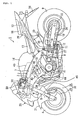
- Figure 1 is a side elevational view of a motorcycle, incorporating a selected illustrative embodiment of the present invention.
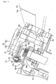
- Figure 2 is a side elevational view, partly in section, showing an attaching structure for a steering damper in the motorcycle of FIG 1.
- Figure 3 is a plan view showing the attaching structure for a steering damper in the motorcycle of FIG 1.
- Figure 4(a) is a top plan view of a first bracket for attaching the steering damper; Figure 4(b) is a side elevational view of the first bracket for attaching the steering damper, and Figure 4(c) is a sectional view of the first bracket for attaching the steering damper, taken along line A-A of Figure 4(a).
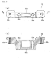
- Figure 5(a) is a plan view of a second bracket for attaching the steering damper; and Figure 5(b) is a sectional view of the second bracket for attaching the steering damper, taken along line B-B of Figure 5(a).
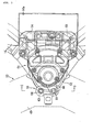
- Figure 6 is a sectional view of the motorcycle attaching structure of Figure 3, taken along line C-C of FIG. 3.
- Figure 7 is a top plan view of the steering damper.
- Figure 8 is a detail view of the steering damper of Figure 7, as viewed in the direction indicated by an arrow mark D of FIG 7.
- Figure 9 is a bottom plan view of the steering damper.
- Figure 10 is a sectional view of the steering damper.
- Figure 11 is a plan view, partly in section, of a housing body of the steering damper.
- Figure 12 is a sectional view of the steering damper, taken along line E-E of FIG 10.
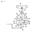
- Figure 13 is a schematic view showing a configuration of the steering damper.
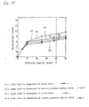
- Figure 14 is a maximum attenuation characteristic diagram of a steering damper system.
- Figure 15 is a maximum attenuation characteristic diagram of the steering damper system when the product dispersion of an electric pressure control valve is at an upper limit and the product dispersion of a relief valve is at a lower limit.
- Figure 16 is a maximum attenuation characteristic diagram of the steering damper system when the product dispersion of an electric pressure control valve is at a lower limit and the product dispersion of a relief valve is at an upper limit.
- Referring now to the drawings, a motorcycle 1 includes a
vehicle body frame 2 substantially at the center thereof, as shown in FIG 1. Ahead pipe 3 is provided at a front end of thevehicle body frame 2, and a front fork 5 is supported on thehead pipe 3 through a steering stem 6. The front fork 5 rotatably supports afront wheel 4 at the lower end thereof. - The
vehicle body frame 2 also includes amain frame 7, which extends obliquely rearwardly and downwardly from thehead pipe 3. Themain frame 7 is bifurcated and forks to the left and right as it extends behind thehead pipe 3. Themain frame 7 further extends rearwardly through a bent portion thereof, as shown. Apivot connection 8 is provided at a front end portion of a substantially central portion of the portion of themain frame 7 which extends downwardly, and arear fork 10 is supported by thepivot connection 8 for rocking motion. - A
rear wheel 9 is supported on the back of therear fork 10. Further, an intermediate portion of therear fork 10 is connected to themain frame 7 through a rear cushion 11 and alink portion 12. - A
seat frame 13 is connected rearwardly of themain frame 7. Afuel tank 14 is disposed above themain frame 7, and anengine body 15 of a water-cooled parallel four-cylinder engine is disposed below themain frame 7. Anengine hanger 16 extends downwardly from a front portion of themain frame 7. Theengine hanger 16 cooperates with the other engine body supporting attaching portions provided on themain frame 7 to support theengine body 15. - A
seat 17 for a driver and apillion 18 for a passenger are supported on theseat frame 13 rearwardly of thefuel tank 14. Astep 19 for a driver is attached to a rear portion of thepivot portion 8 of thevehicle body frame 2, and astep 20 for a passenger is attached to a lower portion of theseat frame 13. Further, a pair of left andright handlebars top bridge 49. - A front portion of the vehicle body of the motorcycle 1 is covered with a
front cowl 25, and the periphery of theseat frame 13 is covered with arear cowl 26. Further, a retractable side stand 27 is disposed at a lower portion of the left side of thevehicle body frame 2, such that the vehicle body of the motorcycle 1 is supported in a leftwardly inclined upright state by theside stand 27. - A
brake caliper 28 is attached to a lower end portion of the front fork 5 and abrake rotor 29 corresponding to thebrake caliper 28 is attached to thefront wheel 4, thereby forming afront brake apparatus 30. Further, afront fender 31 is attached to a lower end portion of the front fork 5 and covers an upper portion of thefront wheel 4. - A
rear sprocket wheel 32 is attached to the left wide of therear wheel 9 for integral rotation with therear wheel 9. Adrive chain 34 extends between and around therear sprocket wheel 32 and a drivingsprocket wheel 33 disposed on the left side of a rcar portion of theengine body 15 so that driving force of theengine body 15 is transmitted to therear wheel 9. - A front side
rear fender 35 is attached to an upper portion of therear fork 10 and covers the front side of an upper portion of therear wheel 9. Arear fender 36 is attached to a lower portion of therear cowl 26 and covers the rear side of an upper portion of therear wheel 9. It is to be noted that a rear brake apparatus having a configuration similar to that of thefront brake apparatus 30 for thefront wheel 4 is provided on therear fork 10. - A
cylinder body 40 of theengine body 15 is disposed in a rather forwardly inclined state on acrankcase 41.Throttle bodies 42, corresponding to the individual cylinders, are connected to a rear portion of thecylinder body 40, and arc further connected to an aircleaner case 43 disposcd between themain frame 7 and thefuel tank 14. Further,exhaust pipes 44 corresponding to the cylinders are connected to a front portion of thecylinder body 40. Theexhaust pipes 44 extend forwardly from afront wall 45 of thecylinder body 40 and are curved downwardly, and then extend rearwardly of theengine body 15 passing the front and the bottom of thecrankcase 41. - The steering stem 6, the
top bridge 49 disposed above and in parallel to a bottom bridge of the steering stem 6, thehandlebars 21 and so forth form asteering system 50 for steering thefront wheel 4. A steeringdamper 51 is interposed between the steeringsystem 50 and the vehicle body frame 2 (refer to FIGS. 2 and 3). - Two types of steering
damper 51 including the rod type and the rotary type are usually available, and thesteering damper 51 used here is of the rotary type, which is superior in terms of compact size. - As shown in FIG. 2, the steering
damper 51 includes adamper housing 52 and adamper shaft 53, which extends through a lower face portion of thedamper housing 52, and projects outwardly therefrom. As best seen in Figure 3, thedamper housing 52 is attached to an integral attachingflange 3a on thehead pipe 3, via first andsecond brackets flange 3a is integrally provided on, and extends rearwardly from thehead pipe 3, and is substantially transverse to a longitudinal axis of the head pipe. - The
damper shaft 53 is attached to thetop bridge 49 through alinkage 56, which will be described in further detail below. - As shown in FIG. 4, the
first bracket 54 has a substantially box-like shape and is hollow in the inside thereof. Thefirst bracket 54 includes left and rightside wall portions bottom plate portion 54b, and a substantially Y-shapedleg portion 54c. - The
leg portion 54c is connected to rear end portions of theside wall portions 54a andbottom plate portion 54b. Attachingholes side plate portions leg portion 54c, and thesteering damper 51 is bolted through the attachingholes 54d. - Further, attaching
object holes bottom plate portion 54b while attachingobject holes leg portion 54c. Thefirst bracket 54 is bolted to the attachingportion 3a of thehead pipe 3 through the attachingobject holes 54e. - As shown in FIG 5, the
second bracket 55 has abase portion 55a formed in a substantially parallelepiped block shape, and left andright wing portions - Attaching
object holes base portion 55a so as to be coaxial with the attachingobject holes first bracket 54. - During installation of the
brackets second bracket 55 is placed above thefirst bracket 54, and a single bolt is inserted into each of corresponding ones of the attachingobject holes 54f and the attachingobject holes 55c, aligned coaxially with each other. Thesecond bracket 55 is thereby attached to the attachingportion 3a of thehead pipe 3, together with thefirst bracket 54. - The
linkage 56 will now be described. As shown in FIGS. 2, 3 and 6, a steeringtorque transfer arm 60 is fixedly attached, at anend portion 60a thereof, to thedamper shaft 53, which projects downwardly from the steeringdamper 51. - A spectacle-shaped link member 63 (Figure 3) is supported spherically, at one end portion thereof, on the bifurcated
other end portion 60b of the steeringtorque transfer arm 60 through abolt 61, aball member 62 fitted on an outer periphery of thebolt 61 and so forth. Further, thelink member 63 is supported spherically at the other end portion thereof on an attachingportion 49a formed on thetop bridge 49 through abolt 64 and aball member 65 fitted on an outer periphery of thebolt 64. - In short, the
linkage 56, for transmitting a motion of the top bridge to thedamper shaft 53, is formed from the steeringtorque transfer arm 60,bolts ball members link member 63. Through thislinkage 56, pivotal movement of the steering column, caused by movement of thehandlebars 21 winch moves thetop bridge 49, is transferred to pivotal movement of thedamper shaft 53. - The
damper shaft 53 of thesteering damper 51 is indirectly attached to thetop bridge 49 through thelinkage 56 including the steeringtorque transfer arm 60. Thehousing 52 of thesteering damper 51 extends rearwardly of thetop bridge 49, as shown. - A
linear solenoid 69, which is an example of an actuator for driving and controlling a hydraulicpressure control valve 68, is attached to and disposed below thehousing extension 52a which extends rearwardly on thedamper housing 52, behind thetop bridge 49. - A
recess 14a is formed at a front portion of thefuel tank 14, in order to prevent interference of thefuel tank 14 with the steeringdamper 51 and/or the first andsecond brackets reference numeral 70 denotes an ignition switch disposed forwardly of thehead pipe 3. - As shown in FIGS. 7 to 11, the
damper housing 52 of thesteering damper 51 includes abody 71 and acap 72 removably attached to the top of the body. A recess 73 (Fig. 11) is formed in an upper face portion of thebody 71, and is covered with thecap 72 to form anoil chamber 74. Theoil chamber 74 is partitioned into left andright oil chambers vane 75. - As shown in FIG. 10, a
base portion 75 a of thevane 75 is formed in a cylindrical shape, and thedamper shaft 53 is connected in a fixed state to thecylindrical portion 75a through a fixing mechanism such as splines, so that thevane 75 rotates integrally and concurrently together with thedamper shaft 53. Further, thevane 75 is supported for rocking motion with respect to thedamper housing 52 by thedamper shaft 53. -
Grooves 75b are formed continuously along an upper end portion, a lower end portion and a rear end portion of thevane 75, and these grooves generally face toward an inner peripheral face of theoil chamber 74. Aseal member 76 is fitted in thegrooves 75b, and has a channcl shape conforming to the shape of thegrooves 75b. Here, thegrooves 75b and theseal member 76 do not extend to thedamper shaft 53, but are formed to extend or be fitted to a position with a gap left from thedamper shaft 53. - As shown in FIG 10, sealing
washers damper shaft 53, such that they contact upper and lower faces of thebase portion 75a of thevane 75. The outer peripheries of the upper andlower sealing washers seal member 76. In short, the twooil chambers damper housing 52 are held liquid-tight from each other by theseal member 76 and the sealingwashers damper shaft 53. - A
bushing 78 is fitted at a portion of thedamper shaft 53 on the upper side thereof, with respect to the location of thedamper shaft 53 at which thesealing washer 77a is fitted. Further, acirclip 79 is fitted at another portion of thedamper shaft 53, below thebushing 78 and above thevane 75. Meanwhile, abushing 80 and anoil seal 81 are fitted at a portion of thedamper shaft 53 below the lowerside sealing washer 77b. - As shown in FIGS. 10 to 12,
oil paths body 71 of thedamper housing 52, and these oil paths communicate with the left andright oil chambers oil paths oil chambers valves oil paths - Further, an
oil connecting path 86 is formed at and substantially perpendicularly to rear end portions of theoil paths oil paths oil connecting path 86 is connected to a lower stageside oil path 87 through the hydraulicpressure control valve 68 disposed in a vertical direction, and theoil path 87 extends substantially perpendicularly to the oil path 86 (refer to FIG. 12). Theoi path 87 extends forwardly from the location of the hydraulicpressure control valve 68 to a location below theoil chamber 74, and is communicated at a front end thereof with anotheroil path 88, which extends substantially perpendicularly to theoil path 87. Checkvalves oil path 88. - The opposite left and right ends of the
oil path 88 further extend to the side edges of thehousing body 71, and then extend upwardly until they are communicated with the left andright oil chambers oil paths body 71 of thedamper housing 52. - The
check valves check valve 85 as an example. Avalve seat 85b is provided in avalve body 85a, and aball 85c is accommodated in thevalve body 85a. Theball 85c is biased with suitable biasing force by aspring 85d such that it contacts thevalve seat 85b. Thecheck valve 85 permits the fluid to flow in a direction in which theball 85c is spaced away from thevalve seat 85b against the biasing force of thespring 85d, but blocks the working fluid to flow in the reverse direction. - Here, the
check valves 85 permit the working fluid to flow from theoil chambers oil path 86 side through theoil paths check valves 89 permit the working fluid to flow to theoil chambers oil path 88, but block the working fluid to flow in the reverse direction. - As shown in FIG 10, the hydraulic
pressure control valve 68 varies the attenuating force of thesteering damper 51. The hydraulicpressure control valve 68 includes avalve seat 68b provided in avalve body 68a and has apoppet 68c accommodated therein in an opposing relationship to thevalve seat 68b. Thepoppet 68c is biased suitably with biasing force by aspring 68d interposed between a bottom spring seat of thepoppet 68c and thevalve seat 68b so that it is spaced away from thevalve seat 68b. - An upper end of a
push rod 68e is inserted in a lower end of thepoppet 68c, and a lower end of thepush rod 68e is connected to thelinear solenoid 69. The pushing force of thepoppet 68c is adjusted by an exciting operation of thelinear solenoid 69, such that a head portion of thepoppet 68c contacts thevalve seat 68b, against the biasing force of thespring 68d. - In particular, according to the hydraulic
pressure control valve 68, the position of thepoppet 68c is determined by the pressure difference between the left andright oil chambers damper housing 52, communicating with the spaces in the head portion and the bottom portion of thepoppet 68c, and also by the biasing force of thespring 68d and the force of thelinear solenoid 69, acting through thepush rod 68e. - When the resultant force of the poppet pressing force caused by the pressure difference between the left and
right oil chambers spring 68d is lower than the exciting force of thelinear solenoid 69, thepoppet 68c contacts thevalve seat 68b to control the hydraulicpressure control valve 68 to a closed state. - However, when the resultant force of the poppet pressing force, caused by the pressure difference between the left and
right oil chambers spring 68d, exceeds the exciting force of thelinear solenoid 69, thepoppet 68c is spaced away from thevalve seat 68b, to partially or fully open the hydraulicpressure control valve 68. Then, when the working fluid passes through a gap between thevalve seat 68b and thepoppet 68c of the hydraulicpressure control valve 68, predetermined attenuating force is obtained. - It is to be noted that the
linear solenoid 69 is controlled by a control section (not shown), so that higher exciting force is exhibited as the vehicle speed or the acceleration of the vehicle body increases. - As shown in FIG 12, a
bypass oil path 91 is formed between theoil path 86 and theoil path 87, and apressure relief valve 92 is interposed in thebypass oil path 91. Thepressure relief valve 92 is structured such that it includes avalve seat 92b, provided in a valve body 92a and having aball 92c accommodated therein, and theball 92c is biased toward thevalve scat 92b side with suitable biasing force by a spring 92d. While theball 92c normally contacts thevalve scat 92b, if the pressure difference between theoil path 86 and theoil path 87 becomes highcr than a predetermined value, then theball 92c is moved so as to be spaced away from the valve seat against the biasing force of the spring 92d, by pressing force based on the pressure difference, to open therelief valve 92 and to thereby moderate the pressure difference between theoil path 86 and theoil path 87. - Here, a pressure control valve 100 for substantially varying the attenuating force upon operation of the
steering system 50 is formed from the electricpressure control valve 68 and therelief valve 92, as a mechanical pressure control valve, disposed in parallel to each other between the entrance side oil path and the exit side oil path. - Further, the maximum opening pressure of the electric
pressure control valve 68 is set such that the lower limit value ((b) in FIG. 14) to the dispersion of the maximum releasing pressure is higher than the lower limit value ((d) in FIG 14) to the dispersion of the valve opening pressure of therelief valve 92. More preferably, the maximum opening pressure of the electricpressure control valve 68 is additionally set such that the lower limit value ((b) in FIG 14) to the dispersion of the maximum releasing pressure of the electricpressure control valve 68 is lower than the upper limit value ((c) in FIG. 14) to the dispersion of the valve opening pressure of therelief valve 92. In short, the maximum opening pressure of the electricpressure control valve 68 is set such that the lower limit value ((b) in FIG. 14) to the dispersion of the maximum releasing pressure of the electricpressure control valve 68 is positioned between the upper limit value ((c) in FIG. 14) and the lower limit value ((d) in FIG 14) to the dispersion of the valve opening pressure of therelief valve 92. - A
free piston 93 is communicated with theoil path 88. Thefree piston 93 is structured such that it includes acylinder 93a formed integrally with thebody 71, apiston 93c for defining areservation portion 93b for reserving the working fluid forwardly of thecylinder 93a, and aspring 93d for biasing thepiston 93c to the reservation portion side. In thefree piston 93, when the working fluid filled in a closed space formed from theoil chambers oil paths piston 93c moves to change the volume of thereservation portion 93b to thereby absorb the thermal expansion and so forth of the working fluid. - Subsequently, action of the attaching structure for the steering damper in the motorcycle having the configuration described above is described.
- If the
handlebars 21 are turned, for example, to the left side upon running, then thetop bridge 49 is turned in the same direction integrally with thehandlebars 21, and this motion of thetop bridge 49 is transmitted to thedamper shaft 53 of thesteering damper 51 through thelinkage 56. Then, thedamper shaft 53 is also turned in the counterclockwise direction in FIG 11, and thereupon thevane 75 is turned in the same direction ((a) in FIG 11). Thereupon, theoil chamber 74b is narrowed to increase the pressure of the working fluid filled therein, and the working oil in theoil chamber 74b moves directly into theoil chamber 74a on the other side through the gap between thevane 75 and the inner peripheral face which defines theoil chamber 74 and so forth. While some working fluid directly moves between theoil chambers oil chamber 74b which is narrowed becomes high, the working fluid passes through theoil path 84 and thecheck valve 85 into theoil path 86, and then moves from theoil path 86 to the hydraulicpressure control valve 68. - The hydraulic
pressure control valve 68 normally is in a closed state because thepoppet 68c contacts thevalve seat 68b under the force of thelinear solenoid 69, and for example, even if some pressure of the working fluid is applied from theoil chamber 74b side, the closed state is kept. However, if the resultant force of the pressing force based on the pressure difference between the left andright oil chambers spring 68d exceeds the exciting force ofthc lincar solenoid 69, then thepoppet 68c is spaced away from thevalve seat 68b to open the hydraulicpressure control valve 68. At this time, the working fluid in theoil path 86 passes through the gap between thevalve scat 68b and thepoppet 68c of the hydraulicpressure control valve 68 to theoil path 87, and further moves from theoil path 87 to the leftside oil chamber 74a through theoil path 88 and thecheck valve 89. The resistance when the working fluid passes through the hydraulicpressure control valve 68 and so forth generates attenuating force in this manner and acts upon the handlebars 21. In short, the attenuating force acts as resisting force when thehandlebars 21 are turned, and further acts as resisting force against instantaneous turning force acting upon the handlebars. - While the foregoing description applies to a case wherein the
handlebars 21 are turned to the left side, it similarly applies also to another case wherein thehandlebars 21 are turned to the right side. - The
linear solenoid 69 is controlled in accordance with the vehicle speed or the acceleration of the vehicle body and is controlled by a control section (not shown) so that, for example, the exciting force increases as the vehicle speed increases or as the acceleration of the vehicle body increases. Accordingly, at this time, the opening timing of the hydraulicpressure control valve 68 is delayed, and besides, even after the hydraulicpressure control valve 68 is opened, the valvc opening is smaller by an amount corresponding to the increase of the exciting force and increased attenuating force is exhibited. In short, as the vehicle speed increases or as the acceleration increases, increased attenuating force is exhibited. - Accordingly, when the vehicle body runs at a low speed or at a low acceleration, importance is attached to handling properties, and the
handlebars 21 can be turned with comparatively low force. However, when the vehicle body runs at a high speed or at a high acceleration, high attenuating force acts when thehandlebars 21 are turned. Consequently, occurrence of a kickback phenomenon can be reduced. - It is to be noted that, during control of the
steering damper 51, if the pressure of the working fluid in one of the left andright oil chambers pressure control valve 68 becomes higher than the value set in advance, therelief valve 92 is opened. - Consequently, the working fluid in the
oil path 86 is permitted to flow into theoil path 87 through thebypass oil path 91, to thereby moderate the increased pressure difference. In other words, pressure of the working fluid in one of the oil chambers is prevented from becoming excessively high. - Further, if the temperature of the working fluid filled in the
oil chamber 74,oil paths piston 93c in thefree piston 93 moves within thecylinder 93a, in response to the expansion or contraction of the working fluid, to thereby absorb the volume variation of the working fluid. - In the embodiment described above, the
damper housing 52 of thesteering damper 51 extends rearwardly farther than thetop bridge 49, and thelinear solenoid 69 which composes the actuator for the hydraulicpressure control valve 68 is advantageously located below theextension 52a of thedamper housing 52. Therefore, effective utilization of the gap between thetop bridge 49 and thefuel tank 14 disposed rearwardly of thetop bridge 49 can be anticipated, and thelinear solenoid 69 can be advantageously located while the overall height of thesteering damper 51 is suppressed. - Further, since the
linear solenoid 69 does not project upwardly from thedamper housing 52, thelinear solenoid 69 can be prevented from interfering with a movable member in the proximity of thetop bridge 49 which moves together with the handlebars or the like. Furthermore, the overall length of thesteering damper 51 can be reduced, when compared with an alternative case wherein the linear solenoid is attached such that it projects rearwardly, and the degree of freedom in layout of thefuel tank 14 and so forth increases as much. - Further, when the
damper shaft 53 is attached to thesteering system 50, it is attached through thelinkage 56. Therefore, when thedamper housing 52 is to be attached to thetop bridge 49, even if thedamper shaft 53 is attached in a displaced relationship from the axial line of thehead pipe 3 or the steering stem 6, the function of thesteering damper 51 is not deteriorated. - In particular, it is preferable to attach the
steering damper 51 such that thedamper shaft 53 may be coaxial with the axial line of thehead pipe 3 or the steering stem 6. However, it cannot be avoided that thedamper shaft 53 is assembled in a displaced relationship from the axial line of the steering stem 6 or the like because of failure of the accuracy of parts, the assembly error of the parts and so forth. - In this instance, where the
damper shaft 53 is attached directly to thetop bridge 49, since the centers of rotation of them are displaced from each other, smooth movement is not assured, and the function of thesteering damper 51 cannot be exhibited. Here, since thedamper shaft 53 is attached to thesteering system 50 through thelinkage 56, occurrence of such a trouble as just described can be prevented. - Further, since, in the
steering damper 51 described above, the oil paths are formed in two upper and lower stages in thedamper housing 52, a compact configuration of thedamper housing 52 in a plane can be anticipated when compared with that in an alternative case wherein the oil paths are formed in one stage. Consequently, the degree of freedom in layout of thefuel tank 14 and so forth further increases. - It is to be noted that the embodiment described above is only one example of an illustrative embodiment of the present invention, and can be modified suitably when necessary without departing from the spirit and scope of the present invention.
- For example, in the embodiment described above, the
damper housing 52 of thesteering damper 51 is attached to thevehicle body frame 2 side, while thedamper shaft 53 is attached to thesteering system 50. However, thedamper housing 52 of thesteering damper 51 may be attached to thesteering system 50 while thedamper shaft 53 is attached to thevehicle body frame 2 side conversely. - Further, while, in the embodiment described above, the
damper housing 52 of thesteering damper 51 is attached to thehead pipe 3, it may otherwise be attached directly or through a stay to a rearward extension of thevehicle body frame 2 which extends rearwardly from thehead pipe 3. - Furthermore, while, in the embodiment described above, the
linear solenoid 69 is used as the actuator for the hydraulicpressure control valve 68, the actuator is not limited to this, but another alternative actuator may be used instead, which utilizes a hydraulic pressure or the like. - As described in detail above, according to the attaching structure for a steering damper in a motorcycle of the invention of the present application, effective utilization of the gap between the top bridge and the fuel tank or the like which is a part normally disposed rearwardly of the top bridge can be anticipated. Besides, even if the actuator for driving the hydraulic pressure control valve is comparatively great, it can be advantageously located while the height thereof is suppressed low.
- Further, the actuator does not project upwardly from the housing, and therefore, the actuator can be prevented from interfering with a movable member in the proximity of the top bridge which moves together with a handlebar or the like. Furthermore, the overall length of the steering damper can be reduced, and this increases the degree of freedom in layout of the fuel tank and other parts.
- The lower limit value ((b) in FIG 14) to the dispersion of the maximum opening pressure of the electric
pressure control valve 68 is set so as to be positioned between the upper limit value ((c) in FIG 14) and the lower limit value ((d) in FIG. 14) to the dispersion of the valve opening pressure of therelief valve 92. At this time, since the valve opening when the maximum attenuating force is exhibited is performed by that one of therelief valve 92 and the electricpressure control valve 68 which has a lower opening pressure, therelief valve 92 which has a smaller dispersion as a product is likely to be opened earlier. Accordingly, the dispersion width of the maximum attenuating force generated in the system and exhibited by synthesis of therelief valve 92 and the electricpressure control valve 68 depends upon therelief valve 92. - In short, the lower limit value to the dispersion of the maximum attenuating force generated in the system and exhibited by synthesis of the
relief valve 92 and the electricpressure control valve 68 depends upon the lower limit value to the dispersion width of therelief valve 92 as seen in FIG. 15 while the upper limit value to the dispersion depends upon the upper limit value of therelief valve 92 as seen in FIG 16. As a result, the dispersion width of the maximum attenuating force generated in the system and exhibited by synthesis of therelief valve 92 and the electricpressure control valve 68 is reduced. - Incidentally, for example, where the steering angular speed of the steering system is in the proximity of Z as seen in FIG. 14, in a conventional steering damper which only includes the electric
pressure control valve 68, the dispersion width of the maximum attenuating force is "X" which depends upon the dispersion of the electricpressure control valve 68. In contrast, in thesteering damper 51 of the system of the present embodiment wherein therelief valve 92 and the electricpressure control valve 68 are arranged in parallel to each other, the dispersion width of the maximum attenuating force is "Y" which depends upon the dispersion of therelief valve 92, and the value of "Y" is much smaller than the value of "X". - Although the present invention has been described herein with respect to a specific illustrative embodiment thereof, the foregoing description is intended to be illustrative, and not restrictive. Those skilled in the art will realize that many modifications of the preferred embodiment could be made which would be operable. All such modifications which are within the scope of the claims are intended to be within the scope and spirit of the present invention.
- A steering damper in a motorcycle includes a vane partitioning a chamber in a damper housing into two oil chambers, wherein hydraulic fluid flows between the two chambers to generate attenuating force. The steering damper also includes a damper shaft connected to the vane and supporting the vane for rocking motion with respect to the housing, and a hydraulic pressure control valve. The housing is attached to a head pipe, and the damper shaft is attached to a steering system. When the head pipe is to be attached to the housing, the housing is extended rearwardly behind a top bridge, and a linear solenoid for driving and controlling the hydraulic pressure control valve is attached to the housing and disposed below the extension thereof.
Claims (13)
- A rotary steering damper for a motorcycle, said steering damper comprising;
a damper housing having an oil chamber formed therein and having a plurality of fluid flow channels in fluid communication with said oil chamber;
a damper shaft attached to and extending downwardly from said damper housing;
a vane disposed in the oil chamber of the housing and attached to the shaft for concurrent pivotal movement therewith, said vane operating to effectively partition the housing oil chamber into left and right oil chambers; and
a hydraulic pressure control valve for varying an attenuating force of said steering damper;
wherein, upon pivotal rocking motion of said vane in said housing, working fluid flows between the left and right oil chambers to generate attenuating force,
and wherein said housing is adapted to be attached to one of a vehicle body frame side and a steering system side while said shaft is adapted to be attached to the other of said vehicle body frame side and said steering system side, and said housing is adapted to be disposed above a top bridge;
wherein said damper housing comprises a housing extension which extends rearwardly behind said top bridge; and wherein said steering damper further comprises an actuator for said hydraulic pressure control valve, said actuator being disposed below said housing extension. - A rotary steering damper according to claim 1, characterized in that said housing is adapted to be attached to said vehicle body frame side, and said shaft is adapted to be attached to said steering system side.
- A rotary steering damper according to claim 1, wherein the actuator comprises an electric solenoid.
- A rotary steering damper according to claim 1, wherein said housing comprises a base and a lid removably attached to the base.
- A steering damper kit for use with a motorcycle, said kit comprising the rotary steering damper of claim 1, a linkage member comprising dual pivot connections, and a bifurcated steering torque transfer arm for connecting between said linkage member and said damper shaft of said steering damper.
- A steering damper for a vehicle wherein a pressure control valve is interposed in an oil path formed in a damper housing provided between a vehicle body frame and a steering system such that said pressure control valve is controlled to vary the attenuating force upon operation of said steering system, characterized in that said pressure control valve comprises:an electric pressure control valve provided in a connecting oil path for communicating an exit side oil path into which working fluid is discharged from an oil chamber of said damper housing and an entrance side oil path along which the working fluid returns to said oil chamber and operable to change the attenuating force upon operation of said steering system in accordance with an electric signal; anda mechanical pressure control valve provided in a bypass oil path provided in parallel to said electric pressure control valve in such a manner as to open when the pressure in said bypass oil path becomes equal to a predetermined value.
- A steering damper for a vehicle according to claim 6, wherein a maximum opening pressure of said electric pressure control valve is set so that a lower limit value to a dispersion thereof is higher than a lower limit value to a dispersion of an opening pressure of said mechanical pressure control valve.
- A motorcycle, comprising a frame having a head pipe with an integral flange extending rearwardly from a top portion thereof, and a steering column pivotally attached to said head pipe, said motorcycle further comprising a rotary steering damper comprising;a damper housing having an oil chamber formed therein and having a plurality of fluid flow channels in fluid communication with said oil chamber;a damper shaft attached to and extending downwardly from said damper housing;a vane disposed in the oil chamber of the housing and attached to the shaft for concurrent pivotal movement therewith, said vane operating to effectively partition the housing oil chamber into left and right oil chambers; anda hydraulic pressure control valve disposed in said damper housing for varying an attenuating force of said steering damper;wherein, upon pivotal rocking motion of said vane in said housing, oil flows between the left and right oil chambers to generate attenuating force, and wherein said housing is attached to one of a vehicle body frame side and a steering system side of said motorcycle, while said shaft is attached to the other of said vehicle body frame side and said steering system side, and said housing is disposed above a top bridge of said motorcycle;
wherein said damper housing further comprises a housing extension which extends rearwardly behind said top bridge; and wherein said steering damper further comprises an actuator for said hydraulic pressure control valve, said actuator being disposed below said housing extension. - The motorcycle of claim 8, wherein said damper housing is attached to said vehicle body frame side, and said shaft is attached to said steering system side.
- The motorcycle of claim 8, wherein the actuator comprises an electric solenoid.
- The motorcycle of claim 8, wherein said damper housing comprises a base and a lid removably attached to the base.
- The motorcycle of claim 8, further comprising a linkage member comprising dual pivot connections, and a bifurcated steering torque transfer arm connecting said linkage member and said damper shaft of said steering damper.
- The motorcycle of claim 8, further comprising a plurality of brackets situated between the steering damper and the flange on the head pipe.
Applications Claiming Priority (4)
| Application Number | Priority Date | Filing Date | Title |
|---|---|---|---|
| JP2003079156 | 2003-03-20 | ||
| JP2003079158A JP4198497B2 (en) | 2003-03-20 | 2003-03-20 | Steering damper mounting structure for motorcycles |
| JP2003079156A JP4342820B2 (en) | 2003-03-20 | 2003-03-20 | Steering damper for vehicles |
| JP2003079158 | 2003-03-20 |
Publications (3)
| Publication Number | Publication Date |
|---|---|
| EP1459971A2 true EP1459971A2 (en) | 2004-09-22 |
| EP1459971A3 EP1459971A3 (en) | 2004-11-17 |
| EP1459971B1 EP1459971B1 (en) | 2006-05-24 |
Family
ID=32829024
Family Applications (1)
| Application Number | Title | Priority Date | Filing Date |
|---|---|---|---|
| EP04006414A Expired - Lifetime EP1459971B1 (en) | 2003-03-20 | 2004-03-17 | Vehicle steering damper |
Country Status (3)
| Country | Link |
|---|---|
| US (1) | US7021433B2 (en) |
| EP (1) | EP1459971B1 (en) |
| DE (1) | DE602004000932T2 (en) |
Cited By (7)
| Publication number | Priority date | Publication date | Assignee | Title |
|---|---|---|---|---|
| EP1481882A2 (en) | 2003-05-28 | 2004-12-01 | HONDA MOTOR CO., Ltd. | Steering damper |
| EP1514786A1 (en) * | 2003-09-09 | 2005-03-16 | HONDA MOTOR CO., Ltd. | Vehicle steering damper apparatus, and vehicle incorporating same |
| EP1707483A1 (en) * | 2005-03-31 | 2006-10-04 | Honda Motor Co., Ltd. | Steering damper mounting structure |
| EP1759975A3 (en) * | 2005-08-30 | 2008-05-07 | Showa Corporation | Steering damper apparatus |
| EP2130754A1 (en) * | 2008-06-04 | 2009-12-09 | Yamaha Hatsudoki Kabushiki Kaisha | Steering damper system, and a saddle riding type vehicle having the same |
| EP2261528A3 (en) * | 2005-02-17 | 2011-01-19 | Ralph S. Norman | Fluid stabilizer |
| DE102006002725B4 (en) * | 2005-02-16 | 2014-05-22 | Honda Motor Co., Ltd. | Rotational dampers |
Families Citing this family (17)
| Publication number | Priority date | Publication date | Assignee | Title |
|---|---|---|---|---|
| US7789207B2 (en) * | 2002-06-10 | 2010-09-07 | Norman Ralph S | Stabilizer |
| JP4271468B2 (en) * | 2003-03-20 | 2009-06-03 | 本田技研工業株式会社 | Rotary damper |
| JP4493074B2 (en) * | 2004-02-05 | 2010-06-30 | 本田技研工業株式会社 | Steering damper device for motorcycles |
| JP4555750B2 (en) * | 2004-09-28 | 2010-10-06 | 本田技研工業株式会社 | Steering damper device |
| CN101128659B (en) * | 2005-02-24 | 2010-05-26 | 约翰·W·菲茨杰拉德 | Variable stroke premixed charge compression ignition engine |
| US7631735B1 (en) * | 2006-05-03 | 2009-12-15 | Vanvalkenburgh Charlie N | Mounting system for rotary damper |
| JP4909763B2 (en) * | 2007-02-23 | 2012-04-04 | カヤバ工業株式会社 | Steering damper |
| WO2008108731A1 (en) * | 2007-03-05 | 2008-09-12 | öHLINS RACING AB | Steering damper and device for mounting a steering damper |
| SE532539C2 (en) * | 2007-06-14 | 2010-02-16 | Oehlins Racing Ab | Wing dampers with adjustable damping force |
| US7970511B2 (en) * | 2008-02-06 | 2011-06-28 | Honda Motor Company, Ltd. | Electronic steering damper systems and vehicles including same |
| DE102008011858B4 (en) * | 2008-02-29 | 2009-12-24 | Gebrüder Frei GmbH & Co. KG | Device for damping a rotary movement |
| DE102008002629A1 (en) * | 2008-06-25 | 2009-12-31 | Zf Friedrichshafen Ag | Torsional vibration damper for a motor vehicle chassis |
| AR079383A1 (en) | 2010-12-27 | 2012-01-25 | Fischer Hugo Alfredo | STEERING STABILIZER DEVICE FOR VEHICLES WITH COLUMN AND HANDLEBAR. |
| EP2704943B1 (en) * | 2011-05-05 | 2016-11-23 | Öhlins Racing AB | Steering damper with active adjustment of damping characteristics |
| US9863450B1 (en) * | 2014-04-16 | 2018-01-09 | Rockwell Collins, Inc. | Hydro-mechanical device with preloaded flow regulating assembly |
| US10301792B2 (en) * | 2015-04-30 | 2019-05-28 | Micromatic Llc | Hydraulic dampener for use on mine shovels |
| CN112896401B (en) * | 2021-03-17 | 2022-07-26 | 浙江春风动力股份有限公司 | Motorcycle steering system |
Family Cites Families (10)
| Publication number | Priority date | Publication date | Assignee | Title |
|---|---|---|---|---|
| US2814362A (en) * | 1954-12-06 | 1957-11-26 | Jr Morgan L Sweeney | Vibration damping apparatus |
| US3419114A (en) * | 1967-09-18 | 1968-12-31 | Houdaille Industries Inc | Hydraulic action devices with inertia insensitive snubbing circuit |
| JP4640905B2 (en) | 2001-04-06 | 2011-03-02 | 本田技研工業株式会社 | Steering damper device |
| JP4493068B2 (en) * | 2001-09-07 | 2010-06-30 | 本田技研工業株式会社 | Steering damper device for saddle-ride type vehicles |
| JP4197591B2 (en) * | 2001-12-28 | 2008-12-17 | 本田技研工業株式会社 | Steering damper device |
| JP4197592B2 (en) * | 2001-12-28 | 2008-12-17 | 本田技研工業株式会社 | Steering damper device |
| US6824153B2 (en) | 2002-06-21 | 2004-11-30 | Kayaba Industry Co., Ltd. | Steering device |
| US6802519B2 (en) * | 2002-09-09 | 2004-10-12 | Rtt Motorsports, Llc | Steering damper |
| JP4271468B2 (en) * | 2003-03-20 | 2009-06-03 | 本田技研工業株式会社 | Rotary damper |
| JP4545392B2 (en) * | 2003-05-28 | 2010-09-15 | 本田技研工業株式会社 | Steering damper |
-
2004
- 2004-03-09 US US10/796,572 patent/US7021433B2/en not_active Expired - Fee Related
- 2004-03-17 EP EP04006414A patent/EP1459971B1/en not_active Expired - Lifetime
- 2004-03-17 DE DE602004000932T patent/DE602004000932T2/en not_active Expired - Lifetime
Cited By (15)
| Publication number | Priority date | Publication date | Assignee | Title |
|---|---|---|---|---|
| EP1481882A2 (en) | 2003-05-28 | 2004-12-01 | HONDA MOTOR CO., Ltd. | Steering damper |
| EP1481882A3 (en) * | 2003-05-28 | 2007-07-18 | HONDA MOTOR CO., Ltd. | Steering damper |
| US7267350B2 (en) | 2003-05-28 | 2007-09-11 | Honda Motor Co., Ltd | Steering damper |
| EP1514786A1 (en) * | 2003-09-09 | 2005-03-16 | HONDA MOTOR CO., Ltd. | Vehicle steering damper apparatus, and vehicle incorporating same |
| US7258356B2 (en) | 2003-09-09 | 2007-08-21 | Honda Motor Co., Ltd. | Vehicle steering damper apparatus, and vehicle incorporating same |
| DE102006002725B4 (en) * | 2005-02-16 | 2014-05-22 | Honda Motor Co., Ltd. | Rotational dampers |
| EP2261527A3 (en) * | 2005-02-17 | 2011-01-19 | Ralph S. Norman | Fluid stabilizer |
| EP2261529A3 (en) * | 2005-02-17 | 2011-01-19 | Ralph S. Norman | Fluid stabilizer |
| EP2261528A3 (en) * | 2005-02-17 | 2011-01-19 | Ralph S. Norman | Fluid stabilizer |
| US7712756B2 (en) | 2005-03-31 | 2010-05-11 | Honda Motor Co., Ltd. | Steering damper mounting structure |
| CN100465056C (en) * | 2005-03-31 | 2009-03-04 | 本田技研工业株式会社 | Steering shock absorber mounting structure |
| EP1707483A1 (en) * | 2005-03-31 | 2006-10-04 | Honda Motor Co., Ltd. | Steering damper mounting structure |
| EP1759975A3 (en) * | 2005-08-30 | 2008-05-07 | Showa Corporation | Steering damper apparatus |
| EP2130754A1 (en) * | 2008-06-04 | 2009-12-09 | Yamaha Hatsudoki Kabushiki Kaisha | Steering damper system, and a saddle riding type vehicle having the same |
| US8775024B2 (en) | 2008-06-04 | 2014-07-08 | Yamaha Hatsudoki Kabushiki Kaisha | Steering damper system, and a saddle riding type vehicle having the same |
Also Published As
| Publication number | Publication date |
|---|---|
| US7021433B2 (en) | 2006-04-04 |
| DE602004000932D1 (en) | 2006-06-29 |
| EP1459971A3 (en) | 2004-11-17 |
| US20040200680A1 (en) | 2004-10-14 |
| EP1459971B1 (en) | 2006-05-24 |
| DE602004000932T2 (en) | 2006-11-02 |
Similar Documents
| Publication | Publication Date | Title |
|---|---|---|
| EP1459971B1 (en) | Vehicle steering damper | |
| EP1481882B1 (en) | Steering damper | |
| US7258211B2 (en) | Rotary damper | |
| JP4909763B2 (en) | Steering damper | |
| US7712756B2 (en) | Steering damper mounting structure | |
| EP1514787B1 (en) | Swing arm suspension | |
| EP1580110B1 (en) | Steering damper device | |
| JP4726041B2 (en) | Rotary damper | |
| JP2006022946A (en) | Rotary damper | |
| JP4342820B2 (en) | Steering damper for vehicles | |
| JP4342981B2 (en) | Rotary damper | |
| JP4463489B2 (en) | Steering damper mounting structure for motorcycles | |
| JP4198497B2 (en) | Steering damper mounting structure for motorcycles | |
| JPH0996330A (en) | Rotary damper | |
| JP3727089B2 (en) | Inverted front fork | |
| JP4153390B2 (en) | Vehicle steering damper means | |
| JP3035872B2 (en) | Hydraulic shock absorber | |
| JPH11139329A (en) | Hydraulic control valve device for power steering | |
| JPH1182597A (en) | Vehicle shock absorber | |
| JP6494682B2 (en) | Steering damper device for saddle-ride type vehicles | |
| JP3765017B2 (en) | Hydraulic shock absorber | |
| JP2000120751A (en) | Rotary damper | |
| JP2006144863A (en) | Rotary damper | |
| JPH109323A (en) | Rotary damper | |
| JPH0345487A (en) | Vehicle wheel suspension system |
Legal Events
| Date | Code | Title | Description |
|---|---|---|---|
| PUAI | Public reference made under article 153(3) epc to a published international application that has entered the european phase |
Free format text: ORIGINAL CODE: 0009012 |
|
| AK | Designated contracting states |
Kind code of ref document: A2 Designated state(s): AT BE BG CH CY CZ DE DK EE ES FI FR GB GR HU IE IT LI LU MC NL PL PT RO SE SI SK TR |
|
| AX | Request for extension of the european patent |
Extension state: AL LT LV MK |
|
| PUAL | Search report despatched |
Free format text: ORIGINAL CODE: 0009013 |
|
| 17P | Request for examination filed |
Effective date: 20040810 |
|
| RIC1 | Information provided on ipc code assigned before grant |
Ipc: 7F 16F 9/14 B Ipc: 7B 62K 21/08 A |
|
| AK | Designated contracting states |
Kind code of ref document: A3 Designated state(s): AT BE BG CH CY CZ DE DK EE ES FI FR GB GR HU IE IT LI LU MC NL PL PT RO SE SI SK TR |
|
| AX | Request for extension of the european patent |
Extension state: AL LT LV MK |
|
| 17Q | First examination report despatched |
Effective date: 20050203 |
|
| AKX | Designation fees paid |
Designated state(s): DE GB IT |
|
| GRAP | Despatch of communication of intention to grant a patent |
Free format text: ORIGINAL CODE: EPIDOSNIGR1 |
|
| GRAS | Grant fee paid |
Free format text: ORIGINAL CODE: EPIDOSNIGR3 |
|
| GRAA | (expected) grant |
Free format text: ORIGINAL CODE: 0009210 |
|
| AK | Designated contracting states |
Kind code of ref document: B1 Designated state(s): DE GB IT |
|
| PG25 | Lapsed in a contracting state [announced via postgrant information from national office to epo] |
Ref country code: IT Free format text: LAPSE BECAUSE OF FAILURE TO SUBMIT A TRANSLATION OF THE DESCRIPTION OR TO PAY THE FEE WITHIN THE PRESCRIBED TIME-LIMIT;WARNING: LAPSES OF ITALIAN PATENTS WITH EFFECTIVE DATE BEFORE 2007 MAY HAVE OCCURRED AT ANY TIME BEFORE 2007. THE CORRECT EFFECTIVE DATE MAY BE DIFFERENT FROM THE ONE RECORDED. Effective date: 20060524 |
|
| REG | Reference to a national code |
Ref country code: GB Ref legal event code: FG4D |
|
| REF | Corresponds to: |
Ref document number: 602004000932 Country of ref document: DE Date of ref document: 20060629 Kind code of ref document: P |
|
| PLBE | No opposition filed within time limit |
Free format text: ORIGINAL CODE: 0009261 |
|
| STAA | Information on the status of an ep patent application or granted ep patent |
Free format text: STATUS: NO OPPOSITION FILED WITHIN TIME LIMIT |
|
| 26N | No opposition filed |
Effective date: 20070227 |
|
| REG | Reference to a national code |
Ref country code: GB Ref legal event code: 746 Effective date: 20121113 |
|
| REG | Reference to a national code |
Ref country code: DE Ref legal event code: R084 Ref document number: 602004000932 Country of ref document: DE Effective date: 20121113 |
|
| PGFP | Annual fee paid to national office [announced via postgrant information from national office to epo] |
Ref country code: GB Payment date: 20170315 Year of fee payment: 14 |
|
| PGFP | Annual fee paid to national office [announced via postgrant information from national office to epo] |
Ref country code: IT Payment date: 20170320 Year of fee payment: 14 |
|
| GBPC | Gb: european patent ceased through non-payment of renewal fee |
Effective date: 20180317 |
|
| PG25 | Lapsed in a contracting state [announced via postgrant information from national office to epo] |
Ref country code: IT Free format text: LAPSE BECAUSE OF NON-PAYMENT OF DUE FEES Effective date: 20180317 Ref country code: GB Free format text: LAPSE BECAUSE OF NON-PAYMENT OF DUE FEES Effective date: 20180317 |
|
| PGFP | Annual fee paid to national office [announced via postgrant information from national office to epo] |
Ref country code: DE Payment date: 20190305 Year of fee payment: 16 |
|
| REG | Reference to a national code |
Ref country code: DE Ref legal event code: R119 Ref document number: 602004000932 Country of ref document: DE |
|
| PG25 | Lapsed in a contracting state [announced via postgrant information from national office to epo] |
Ref country code: DE Free format text: LAPSE BECAUSE OF NON-PAYMENT OF DUE FEES Effective date: 20201001 |