EP1459960A1 - Coupling structure of shaft body and shaft joint - Google Patents
Coupling structure of shaft body and shaft joint Download PDFInfo
- Publication number
- EP1459960A1 EP1459960A1 EP04005815A EP04005815A EP1459960A1 EP 1459960 A1 EP1459960 A1 EP 1459960A1 EP 04005815 A EP04005815 A EP 04005815A EP 04005815 A EP04005815 A EP 04005815A EP 1459960 A1 EP1459960 A1 EP 1459960A1
- Authority
- EP
- European Patent Office
- Prior art keywords
- engagement
- shaft
- shaft body
- engagement groove
- flexible member
- Prior art date
- Legal status (The legal status is an assumption and is not a legal conclusion. Google has not performed a legal analysis and makes no representation as to the accuracy of the status listed.)
- Granted
Links
Images





Classifications
-
- F—MECHANICAL ENGINEERING; LIGHTING; HEATING; WEAPONS; BLASTING
- F16—ENGINEERING ELEMENTS AND UNITS; GENERAL MEASURES FOR PRODUCING AND MAINTAINING EFFECTIVE FUNCTIONING OF MACHINES OR INSTALLATIONS; THERMAL INSULATION IN GENERAL
- F16D—COUPLINGS FOR TRANSMITTING ROTATION; CLUTCHES; BRAKES
- F16D1/00—Couplings for rigidly connecting two coaxial shafts or other movable machine elements
- F16D1/06—Couplings for rigidly connecting two coaxial shafts or other movable machine elements for attachment of a member on a shaft or on a shaft-end
- F16D1/08—Couplings for rigidly connecting two coaxial shafts or other movable machine elements for attachment of a member on a shaft or on a shaft-end with clamping hub; with hub and longitudinal key
- F16D1/0852—Couplings for rigidly connecting two coaxial shafts or other movable machine elements for attachment of a member on a shaft or on a shaft-end with clamping hub; with hub and longitudinal key with radial clamping between the mating surfaces of the hub and shaft
- F16D1/0864—Couplings for rigidly connecting two coaxial shafts or other movable machine elements for attachment of a member on a shaft or on a shaft-end with clamping hub; with hub and longitudinal key with radial clamping between the mating surfaces of the hub and shaft due to tangential loading of the hub, e.g. a split hub
-
- B—PERFORMING OPERATIONS; TRANSPORTING
- B62—LAND VEHICLES FOR TRAVELLING OTHERWISE THAN ON RAILS
- B62D—MOTOR VEHICLES; TRAILERS
- B62D1/00—Steering controls, i.e. means for initiating a change of direction of the vehicle
- B62D1/02—Steering controls, i.e. means for initiating a change of direction of the vehicle vehicle-mounted
- B62D1/16—Steering columns
-
- B—PERFORMING OPERATIONS; TRANSPORTING
- B62—LAND VEHICLES FOR TRAVELLING OTHERWISE THAN ON RAILS
- B62D—MOTOR VEHICLES; TRAILERS
- B62D1/00—Steering controls, i.e. means for initiating a change of direction of the vehicle
- B62D1/02—Steering controls, i.e. means for initiating a change of direction of the vehicle vehicle-mounted
- B62D1/16—Steering columns
- B62D1/20—Connecting steering column to steering gear
-
- F—MECHANICAL ENGINEERING; LIGHTING; HEATING; WEAPONS; BLASTING
- F16—ENGINEERING ELEMENTS AND UNITS; GENERAL MEASURES FOR PRODUCING AND MAINTAINING EFFECTIVE FUNCTIONING OF MACHINES OR INSTALLATIONS; THERMAL INSULATION IN GENERAL
- F16D—COUPLINGS FOR TRANSMITTING ROTATION; CLUTCHES; BRAKES
- F16D1/00—Couplings for rigidly connecting two coaxial shafts or other movable machine elements
- F16D1/10—Quick-acting couplings in which the parts are connected by simply bringing them together axially
- F16D1/108—Quick-acting couplings in which the parts are connected by simply bringing them together axially having retaining means rotating with the coupling and acting by interengaging parts, i.e. positive coupling
- F16D1/116—Quick-acting couplings in which the parts are connected by simply bringing them together axially having retaining means rotating with the coupling and acting by interengaging parts, i.e. positive coupling the interengaging parts including a continuous or interrupted circumferential groove in the surface of one of the coupling parts
-
- F—MECHANICAL ENGINEERING; LIGHTING; HEATING; WEAPONS; BLASTING
- F16—ENGINEERING ELEMENTS AND UNITS; GENERAL MEASURES FOR PRODUCING AND MAINTAINING EFFECTIVE FUNCTIONING OF MACHINES OR INSTALLATIONS; THERMAL INSULATION IN GENERAL
- F16D—COUPLINGS FOR TRANSMITTING ROTATION; CLUTCHES; BRAKES
- F16D3/00—Yielding couplings, i.e. with means permitting movement between the connected parts during the drive
- F16D3/16—Universal joints in which flexibility is produced by means of pivots or sliding or rolling connecting parts
- F16D3/26—Hooke's joints or other joints with an equivalent intermediate member to which each coupling part is pivotally or slidably connected
- F16D3/38—Hooke's joints or other joints with an equivalent intermediate member to which each coupling part is pivotally or slidably connected with a single intermediate member with trunnions or bearings arranged on two axes perpendicular to one another
- F16D3/382—Hooke's joints or other joints with an equivalent intermediate member to which each coupling part is pivotally or slidably connected with a single intermediate member with trunnions or bearings arranged on two axes perpendicular to one another constructional details of other than the intermediate member
- F16D3/387—Fork construction; Mounting of fork on shaft; Adapting shaft for mounting of fork
-
- Y—GENERAL TAGGING OF NEW TECHNOLOGICAL DEVELOPMENTS; GENERAL TAGGING OF CROSS-SECTIONAL TECHNOLOGIES SPANNING OVER SEVERAL SECTIONS OF THE IPC; TECHNICAL SUBJECTS COVERED BY FORMER USPC CROSS-REFERENCE ART COLLECTIONS [XRACs] AND DIGESTS
- Y10—TECHNICAL SUBJECTS COVERED BY FORMER USPC
- Y10S—TECHNICAL SUBJECTS COVERED BY FORMER USPC CROSS-REFERENCE ART COLLECTIONS [XRACs] AND DIGESTS
- Y10S464/00—Rotary shafts, gudgeons, housings, and flexible couplings for rotary shafts
- Y10S464/901—Rapid attachment or release
-
- Y—GENERAL TAGGING OF NEW TECHNOLOGICAL DEVELOPMENTS; GENERAL TAGGING OF CROSS-SECTIONAL TECHNOLOGIES SPANNING OVER SEVERAL SECTIONS OF THE IPC; TECHNICAL SUBJECTS COVERED BY FORMER USPC CROSS-REFERENCE ART COLLECTIONS [XRACs] AND DIGESTS
- Y10—TECHNICAL SUBJECTS COVERED BY FORMER USPC
- Y10T—TECHNICAL SUBJECTS COVERED BY FORMER US CLASSIFICATION
- Y10T403/00—Joints and connections
- Y10T403/16—Joints and connections with adjunctive protector, broken parts retainer, repair, assembly or disassembly feature
- Y10T403/1608—Holding means or protector functioning only during transportation, assembly or disassembly
-
- Y—GENERAL TAGGING OF NEW TECHNOLOGICAL DEVELOPMENTS; GENERAL TAGGING OF CROSS-SECTIONAL TECHNOLOGIES SPANNING OVER SEVERAL SECTIONS OF THE IPC; TECHNICAL SUBJECTS COVERED BY FORMER USPC CROSS-REFERENCE ART COLLECTIONS [XRACs] AND DIGESTS
- Y10—TECHNICAL SUBJECTS COVERED BY FORMER USPC
- Y10T—TECHNICAL SUBJECTS COVERED BY FORMER US CLASSIFICATION
- Y10T403/00—Joints and connections
- Y10T403/32—Articulated members
- Y10T403/32606—Pivoted
- Y10T403/32861—T-pivot, e.g., wrist pin, etc.
- Y10T403/32893—T-pivot, e.g., wrist pin, etc. including distinct pin retainer
- Y10T403/32901—Unitary clip or plug
-
- Y—GENERAL TAGGING OF NEW TECHNOLOGICAL DEVELOPMENTS; GENERAL TAGGING OF CROSS-SECTIONAL TECHNOLOGIES SPANNING OVER SEVERAL SECTIONS OF THE IPC; TECHNICAL SUBJECTS COVERED BY FORMER USPC CROSS-REFERENCE ART COLLECTIONS [XRACs] AND DIGESTS
- Y10—TECHNICAL SUBJECTS COVERED BY FORMER USPC
- Y10T—TECHNICAL SUBJECTS COVERED BY FORMER US CLASSIFICATION
- Y10T403/00—Joints and connections
- Y10T403/71—Rod side to plate or side
- Y10T403/7182—Yoke or ring-type connector
Definitions
- the present invention relates to a coupling structure of a shaft body and a shaft joint.
- a steering apparatus for a vehicle comprises: a steering shaft with one end connected to a steering wheel; a transmission shaft having, on one end thereof, a shaft joint connected to the other end of the steering shaft; and a pinion shaft coupled to the other end of the transmission shaft through another shaft joint and having a pinion meshing with the mid portion of a rack shaft which extends in the left and right direction of the vehicle.
- the coupling structure of a shaft joint and a shaft body composed of a steering shaft or a pinion shaft is disclosed, for example, in Japanese Patent Application Laid-Open No. 2000-310232.
- an end of the shaft body is provided with a non-circular engagement portion having a pair of parallel flat faces on a part of circular circumferential surface, and a slip-off preventing groove with both ends facing the flat faces.
- the shaft joint has an engagement groove with which the engagement portion is engaged so that relative rotation is impossible, two concentric bores facing the engagement groove, and a nut member press-fitted into one of the bores.
- a plate body held on the outer periphery of the shaft joint is a plate body comprising: a regulating tongue for regulating the movement of the shaft body within the engagement groove; and a supported portion connected to the regulating tongue through a substantially U-shaped curved portion and supported by the press-fitting of the nut member. Bores corresponding to the above-mentioned respective bores are formed in the supported portion and a position facing the supported portion.
- the shaft body and the shaft joint are coupled up by: inserting the engagement portion of the shaft body into the engagement groove of the shaft joint from the edge side in the depth direction of the engagement groove to engage the engagement portion with the engagement groove; inserting a bolt into the bores of the plate body and the shaft joint and the slip-off preventing groove; and tightening the bolt into the nut member, so that relative movement in the axial direction of the engagement groove and relative rotation are impossible.
- the regulating tongue of the plate body is deflected, and, after the engagement portion is engaged with the engagement groove, the regulating tongue is elastically restored, comes into contact with a side face of the engagement portion, and regulates the W movement of the engagement portion in a direction opposite to the insertion direction.
- the present invention has been made with the aim of solving the above problems, and it is an object thereof to provide a coupling structure of a shaft body and a shaft joint, capable of preventing the shaft body from being inserted into an engagement groove in a state in which it is not engaged in the correct position and allowing the shaft body to be easily pulled out in a longitudinal direction of the engagement groove when canceling the coupling.
- a coupling structure of a shaft body and a shaft joint is a coupling structure for coupling a shaft body and a shaft joint having an engagement groove with which the shaft body is engaged and bores facing the engagement groove by a coupling shaft inserted into the bores, characterized in that the shaft body has a positioning recess in the middle thereof in a longitudinal direction, and the shaft joint has a flexible member which is provided on an outer side in a longitudinal direction of the engagement groove and is to be engaged with the positioning recess.
- the flexible member may be provided more inwardly than the other side face of the engagement groove.
- the coupling structure of a shaft body and a shaft joint according to the present invention is characterized in that the flexible member has a deflection regulating portion facing a side face of the engagement groove.
- the tip of the flexible member may be bent outward in a width direction of the engagement groove.
- FIG. 1 is an exploded perspective view of a coupling structure according to the present invention.
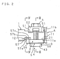
- FIG. 2 is a plan view.
- FIG. 3 is a cross sectional view along the III-III line in FIG. 2.
- FIG. 4 is a cross sectional view along the IV-IV line in FIG. 2.
- This coupling structure is for coupling a shaft body 1 having a non-circular engagement portion 11 on one end thereof to a shaft joint A having an engagement groove 21 with which the engagement portion 11 is engaged so that relative rotation is impossible and two bores 22 and 23 facing the engagement groove 21, by a coupling shaft 6 inserted into the bores 22 and 23.
- One end of the shaft body 1 has: a non-circular engagement portion 11 having a pair of parallel flat faces 11a and 11b on a part of circular circumferential surface and a semi-circular slip-off preventing groove 11c with both ends facing the flat faces 11a and 11b; and a positioning recess 12 extending from one flat face 11a of the engagement portion 11 and having a flat part which is caved in more deeply than the flat face 11a.
- the shaft joint A comprises a joint portion 2 with a substantially U-shaped cross section having the engagement groove 21 with which the engagement portion 11 is engaged so that relative rotation is impossible and two concentric bores 22 and 23 facing the engagement groove 21; a yoke 3 extending from the joint portion 2 and having two concentric through bores (not shown); a locking body 4 press-fitted into the bore 23; and a plate body 5 held on the outer periphery of the joint portion 2 by the press-fitting of the locking body 4.
- two receiving recesses 24 which are caved in more deeply than the side face are provided on the edge side in the depth direction.
- the receiving recesses 24 are provided from the vicinity of both ends in the longitudinal direction of the engagement groove 21 to the vicinity of the bore 22.
- the locking body 4 comprises a press-fit cylindrical portion 41, and an edge portion 43 extending from the press-fit cylindrical portion 41 and having a threaded hole 42.
- the press-fit cylindrical portion 41 is press-fitted into the bore 23, and the edge portion 43 projects from the joint portion 2 to the outside.
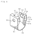
- FIG. 5 is a perspective view of the plate body.
- the plate body 5 is made of spring steel, and comprises: two regulating tongues 51 for regulating the movement of the shaft body 1 in the direction opposite to the insertion direction within the engagement groove 21; a substantially U-shaped curved portion 55 connected to the regulating tongues 51 through a bent portion 52 and having through bores 53 and 54 corresponding to the bores 22 and 23; and a flexible member 57 which is connected to the vicinity of one through bore 54 of the curved portion 55 through a bent portion 56, provided on an outer side in the longitudinal direction of the engagement portion 21 to engage with the positioning recess 12 of the shaft body 1, and deflectable in the width direction of the engagement groove 21.
- the regulating tongues 51 are provided to regulate the movement of the shaft body 1 in the direction opposite to the insertion direction by contact of their ends with a part of the engagement portion 11 on the side opposite to the engagement direction.
- the regulating tongues 51 are apart from each other in the longitudinal direction of the engagement groove 21, face the receiving recesses 24, and are inclined toward the other end of the curved portion 55 from the middle to the tip.
- the through bore 54 of the curved portion 55 is referred to as a supported portion 58 which is supported between the joint portion 2 and the edge portion 43 by the press-fitting of the press-fit cylindrical portion 41.
- the flexible member 57 is provided to prevent engagement of the engagement portion 11 with the engagement groove 21 in a state where the engagement portion 11 is not engaged in the correct position of the engagement groove 21.
- the flexible member 57 comprises: a wide portion 57a extending from the bent portion 56; and a narrow portion 57b which is extending from the wide portion 57a and is narrower than the wide portion 57a.
- the narrow portion 57b is designed to deflect outwardly in the width direction of the engagement groove 21.
- the tip of the narrow portion 57b is bent outwardly in the width direction of the engagement groove 21 so that it is easy to put a finger or the like on the tip of the narrow portion 57b.
- the flexible member 57 is provided more inwardly than the other side face of the engagement groove 21.
- the engagement portion 11 comes into contact with the edge of the wide portion 57a, thereby preventing engagement of the engagement portion 11 with the engagement groove 21.
- the flexible member 57 is inserted into the positioning recess 12 and the narrow portion 57b is engaged with the positioning recess 12.
- the wide portion 57a serves as a deflection regulating portion 57c facing the other side face of the engagement groove 21.
- the deflection regulating portion 57c comes into contact with the side face of the engagement groove 21 and regulates the deflection of the flexible member 57.
- the wide portion 57a is located in a position where it does not come into contact with the engagement portion 11 when the engagement portion 11 is engaged with the engagement groove 21, and therefore the engagement portion 11 does not come into contact with the wide portion 57a when pulling out the shaft body 1 in the longitudinal direction of the engagement groove 21 by deflecting the narrow portion 57b and canceling the engagement of the narrow portion 57b with the positioning recess 12.
- FIG. 6 is a schematic view showing an example of the present invention applied to a steering apparatus.
- This steering apparatus B comprises: a steering shaft 101 with one end connected to a steering wheel 100 for steering; a transmission shaft 102 with one end connected to the other end of the steering shaft 101 through a shaft joint A; and a pinion shaft 103 coupled to the other end of the transmission shaft 102 through another shaft joint A and having a pinion (not shown) meshing with the mid portion of a rack shaft (not shown) which extends in the left and right direction of a vehicle.
- the engagement portion 11 of the shaft body 1 is inserted into the engagement groove 21 from the edge side in the depth direction of the engagement groove 21 and engaged.
- the positioning recess 12 faces the flexible member 57.
- the positioning recess 12 is apart from the flexible member 57 in the longitudinal direction of the engagement groove 21.
- This fixing prevents relative rotation of the shaft body 1, and also prevents the shaft body 1 from being pulled out in the axial direction. Moreover, one side part of the curved portion 55 of the plate body 5 is pressed by the head of the coupling shaft 6, the regulating tongues 51 are displaced toward the inside of the engagement groove 21, and the tips of the regulating tongues 51 come into contact with a part of the engagement portion 11 on a side opposite to the insertion direction, thereby preventing the engagement portion 11 from swinging with the coupling shaft 6 as a fulcrum.
- FIG. 7 is a view showing a state where the shaft body is not engaged in the correct position due to an insufficient amount of engagement between the shaft body and the engagement groove.
- the engagement portion 11 comes into contact with the edge of the wide portion 57a of the flexible member 57 and cannot be inserted into the engagement groove 21. It is therefore possible to judge that the shaft body 1 is not engaged in the correct position due to an insufficient amount of engagement, and to avoid coupling in the state in which the shaft body 1 is not engaged in the correct position due to the insufficient amount of engagement.
- the flexible member 57 has the deflection regulating portion 57c, when the engagement portion 11 comes into contact with the edge of the wide portion 57a, the deflection regulating portion 57c comes into contact with a side face of the engagement groove 21 and can regulate the deflection of the flexible member 57, thereby surely preventing insertion of the engagement portion 11 into the engagement groove 21.
- FIG. 8 is an explanatory view of canceling of the coupling of the shaft body and the shaft joint.
- the shaft body 1 can be pulled out in the longitudinal direction of the engagement groove 21 without being hindered by the flexible member 57.
- the above-explained embodiment illustrates the structure where the plate body 5 having the regulating tongues 51 is provided with the flexible member 57
Landscapes
- Engineering & Computer Science (AREA)
- General Engineering & Computer Science (AREA)
- Mechanical Engineering (AREA)
- Chemical & Material Sciences (AREA)
- Combustion & Propulsion (AREA)
- Transportation (AREA)
- Steering Controls (AREA)
- Connection Of Plates (AREA)
- Snaps, Bayonet Connections, Set Pins, And Snap Rings (AREA)
Abstract
When an insufficient amount of engagement prevents engagement in the correct position, the engagement portion (11) contacts with the flexible member (5) and prevents the shaft body (1) from engaging with the shaft joint (A). When canceling the coupling for maintenance, etc., the engagement of the flexible member (5) with the positioning recess (12) is cancelled by deflecting the flexible member (5) in a width direction of the engagement groove (21). Consequently, the shaft body (1) can be easily pulled out in a longitudinal direction of the engagement groove (21).
Description
- The present invention relates to a coupling structure of a shaft body and a shaft joint.
- A steering apparatus for a vehicle comprises: a steering shaft with one end connected to a steering wheel; a transmission shaft having, on one end thereof, a shaft joint connected to the other end of the steering shaft; and a pinion shaft coupled to the other end of the transmission shaft through another shaft joint and having a pinion meshing with the mid portion of a rack shaft which extends in the left and right direction of the vehicle.
- The coupling structure of a shaft joint and a shaft body composed of a steering shaft or a pinion shaft is disclosed, for example, in Japanese Patent Application Laid-Open No. 2000-310232.
- According to the coupling structure of Japanese Patent Application Laid-Open No. 2000-310232, an end of the shaft body is provided with a non-circular engagement portion having a pair of parallel flat faces on a part of circular circumferential surface, and a slip-off preventing groove with both ends facing the flat faces. The shaft joint has an engagement groove with which the engagement portion is engaged so that relative rotation is impossible, two concentric bores facing the engagement groove, and a nut member press-fitted into one of the bores. In addition, held on the outer periphery of the shaft joint is a plate body comprising: a regulating tongue for regulating the movement of the shaft body within the engagement groove; and a supported portion connected to the regulating tongue through a substantially U-shaped curved portion and supported by the press-fitting of the nut member. Bores corresponding to the above-mentioned respective bores are formed in the supported portion and a position facing the supported portion.
- The shaft body and the shaft joint are coupled up by:
inserting the engagement portion of the shaft body into the engagement groove of the shaft joint from the edge side in the depth direction of the engagement groove to engage the engagement portion with the engagement groove; inserting a bolt into the bores of the plate body and the shaft joint and the slip-off preventing groove; and tightening the bolt into the nut member, so that relative movement in the axial direction of the engagement groove and relative rotation are impossible. In this case, with the insertion of the engagement portion into the engagement groove, the regulating tongue of the plate body is deflected, and, after the engagement portion is engaged with the engagement groove, the regulating tongue is elastically restored, comes into contact with a side face of the engagement portion, and regulates the W movement of the engagement portion in a direction opposite to the insertion direction. - In the coupling structure constructed as described above, however, it is possible to insert the engagement portion of the shaft body into the engagement groove even when the shaft body is not engaged in the correct position of the engagement groove. Moreover, it is also possible to insert the bolt into the bores of the shaft joint and tighten the bolt even when the shaft body is not engaged in the correct position due to an insufficient amount of engagement. Therefore, there is a possibility that the shaft body and the shaft joint cannot be securely coupled. For example, even in a state in which the engagement amount is insufficient because the engagement portion of the shaft body is engaged at a position nearer to the longitudinal end of the engagement groove than the bores into which the bolt is inserted, it is possible to insert the bolt into the bores and tighten the bolt, however the shaft body is not securely coupled because the bolt is not inserted into the slip-off preventing groove of the shaft body. Accordingly, for example, when the above-mentioned coupling structure is adopted in a steering apparatus in which the space around the shaft joint is narrow and the process of coupling the shaft body and the shaft joint is performed in a state in which the coupling portion of the shaft body and the shaft joint cannot be seen directly, there is a possibility that the steering apparatus is mounted in the vehicle body in a state in which the shaft body is not engaged in the correct position due to the insufficient amount of engagement.
- The present invention has been made with the aim of solving the above problems, and it is an object thereof to provide a coupling structure of a shaft body and a shaft joint, capable of preventing the shaft body from being inserted into an engagement groove in a state in which it is not engaged in the correct position and allowing the shaft body to be easily pulled out in a longitudinal direction of the engagement groove when canceling the coupling.
- A coupling structure of a shaft body and a shaft joint according to the present invention is a coupling structure for coupling a shaft body and a shaft joint having an engagement groove with which the shaft body is engaged and bores facing the engagement groove by a coupling shaft inserted into the bores, characterized in that the shaft body has a positioning recess in the middle thereof in a longitudinal direction, and the shaft joint has a flexible member which is provided on an outer side in a longitudinal direction of the engagement groove and is to be engaged with the positioning recess. The flexible member may be provided more inwardly than the other side face of the engagement groove.
- In this coupling structure of a shaft body and a shaft joint, when the shaft body is inserted into the engagement groove in a state in which it is not engaged in the correct position due to an insufficient amount of engagement, a portion of the shaft body other than the positioning recess comes into contact with the flexible member, which should be engaged with the positioning recess, and generates a resistance against the insertion of the shaft body. It is therefore possible to judge that the shaft body is not engaged in the correct position due to an insufficient amount of engagement, and to avoid coupling in the state in which the shaft body is not engaged in the correct position due to an insufficient amount of engagement. On the other hand, in the case where the shaft body is inserted into the engagement groove correctly with a sufficient amount of engagement, since the flexible member is inserted into the positioning recess, it is possible to insert the shaft body into the engagement groove and to couple the shaft body and the shaft joint in a state in which the shaft body is engaged in the correct position with a sufficient amount of engagement. Besides, when canceling the coupling of the shaft body for maintenance, etc., the engagement of the flexible member with the positioning recess can be cancelled by deflecting the flexible member, and consequently, the shaft body can be easily pulled out in the longitudinal direction of the engagement groove.
- The coupling structure of a shaft body and a shaft joint according to the present invention is characterized in that the flexible member has a deflection regulating portion facing a side face of the engagement groove.
- In this coupling structure of a shaft body and a shaft joint, when the shaft body is inserted into the engagement groove in a state in which it is not engaged in the correct position due to an insufficient amount of engagement, a portion of the shaft body other than the positioning recess comes into contact with the flexible member, and the deflection regulating portion comes into contact with one side of the engagement groove with the application of force in a deflection direction to the flexible member, thereby regulating deflection of the flexible member. Accordingly, even when the operability of the flexible member is improved by increasing the flexibility of the flexible member, it is possible to prevent the shaft body from being inserted into the engagement groove in a state in which the shaft body is not engaged in the correct position due to an insufficient amount of engagement, and to more easily perform the process of canceling the coupling of the shaft body for maintenance, etc.
- In the coupling structure of a shaft body and a shaft joint according to the present invention, the tip of the flexible member may be bent outward in a width direction of the engagement groove.
- In this coupling structure of a shaft body and a shaft joint, it is possible to easily put a finger or the like on the tip of the flexible member. Therefore, when canceling the coupling of the shaft body for maintenance, etc., the shaft body can be more easily pulled out in the longitudinal direction of the engagement groove.
- The above and further objects and features of the invention will more fully be apparent from the following detailed description with accompanying drawings.
-
- FIG. 1 is an exploded perspective view of a coupling structure according to the present invention;
- FIG. 2 is a plan view showing the coupling structure of the present invention;
- FIG. 3 is a cross sectional view along the III-III line in FIG. 2;
- FIG. 4 is a cross sectional view along the IV-IV line in FIG. 2;
- FIG. 5 is a perspective view of the plate body of the coupling structure of the present invention;
- FIG. 6 is a schematic view showing an example of the coupling structure of the present invention applied to a steering apparatus;
- FIG. 7 is a view showing a state where the shaft body of the coupling structure of the present invention is not engaged in the correct position due to an insufficient amount of engagement between the shaft body and an engagement groove; and
- FIG. 8 is an explanatory view of canceling of the coupling of the shaft body and a shaft joint in the coupling structure of the present invention.
- The following description will explain the present invention in detail, based on the drawings illustrating an embodiment thereof. FIG. 1 is an exploded perspective view of a coupling structure according to the present invention. FIG. 2 is a plan view. FIG. 3 is a cross sectional view along the III-III line in FIG. 2. FIG. 4 is a cross sectional view along the IV-IV line in FIG. 2.
- This coupling structure is for coupling a
shaft body 1 having anon-circular engagement portion 11 on one end thereof to a shaft joint A having anengagement groove 21 with which theengagement portion 11 is engaged so that relative rotation is impossible and twobores engagement groove 21, by acoupling shaft 6 inserted into thebores - One end of the
shaft body 1 has: anon-circular engagement portion 11 having a pair of parallelflat faces off preventing groove 11c with both ends facing theflat faces positioning recess 12 extending from oneflat face 11a of theengagement portion 11 and having a flat part which is caved in more deeply than theflat face 11a. - The shaft joint A comprises a
joint portion 2 with a substantially U-shaped cross section having theengagement groove 21 with which theengagement portion 11 is engaged so that relative rotation is impossible and twoconcentric bores engagement groove 21; ayoke 3 extending from thejoint portion 2 and having two concentric through bores (not shown); alocking body 4 press-fitted into thebore 23; and aplate body 5 held on the outer periphery of thejoint portion 2 by the press-fitting of thelocking body 4. - In one side face of the
engagement groove 21 of thejoint portion 2, two receivingrecesses 24 which are caved in more deeply than the side face are provided on the edge side in the depth direction. Thereceiving recesses 24 are provided from the vicinity of both ends in the longitudinal direction of theengagement groove 21 to the vicinity of thebore 22. , - The
locking body 4 comprises a press-fitcylindrical portion 41, and anedge portion 43 extending from the press-fitcylindrical portion 41 and having a threadedhole 42. The press-fitcylindrical portion 41 is press-fitted into thebore 23, and theedge portion 43 projects from thejoint portion 2 to the outside. - FIG. 5 is a perspective view of the plate body.
- The
plate body 5 is made of spring steel, and comprises: two regulatingtongues 51 for regulating the movement of theshaft body 1 in the direction opposite to the insertion direction within theengagement groove 21; a substantially U-shapedcurved portion 55 connected to the regulatingtongues 51 through abent portion 52 and having throughbores bores flexible member 57 which is connected to the vicinity of one throughbore 54 of thecurved portion 55 through abent portion 56, provided on an outer side in the longitudinal direction of theengagement portion 21 to engage with thepositioning recess 12 of theshaft body 1, and deflectable in the width direction of theengagement groove 21. - The regulating
tongues 51 are provided to regulate the movement of theshaft body 1 in the direction opposite to the insertion direction by contact of their ends with a part of theengagement portion 11 on the side opposite to the engagement direction. The regulatingtongues 51 are apart from each other in the longitudinal direction of theengagement groove 21, face thereceiving recesses 24, and are inclined toward the other end of thecurved portion 55 from the middle to the tip. Thethrough bore 54 of thecurved portion 55 is referred to as a supportedportion 58 which is supported between thejoint portion 2 and theedge portion 43 by the press-fitting of the press-fitcylindrical portion 41. - The
flexible member 57 is provided to prevent engagement of theengagement portion 11 with theengagement groove 21 in a state where theengagement portion 11 is not engaged in the correct position of theengagement groove 21. Theflexible member 57 comprises: a wide portion 57a extending from thebent portion 56; and anarrow portion 57b which is extending from the wide portion 57a and is narrower than the wide portion 57a. Thenarrow portion 57b is designed to deflect outwardly in the width direction of theengagement groove 21. The tip of thenarrow portion 57b is bent outwardly in the width direction of theengagement groove 21 so that it is easy to put a finger or the like on the tip of thenarrow portion 57b. - The
flexible member 57 is provided more inwardly than the other side face of theengagement groove 21. In the case where theshaft body 1 is engaged with theengagement groove 21 in a state where theengagement portion 11 is not engaged in the correct position due to an insufficient amount of engagement, theengagement portion 11 comes into contact with the edge of the wide portion 57a, thereby preventing engagement of theengagement portion 11 with theengagement groove 21. On the other hand, when theengagement portion 11 is engaged in the correct position, theflexible member 57 is inserted into thepositioning recess 12 and thenarrow portion 57b is engaged with thepositioning recess 12. - Apart of the wide portion 57a serves as a
deflection regulating portion 57c facing the other side face of theengagement groove 21. In the case where theengagement portion 11 is not engaged in the correct position due to an insufficient amount of engagement, if theengagement portion 11 comes into contact with the edge of the wide portion 57a, thedeflection regulating portion 57c comes into contact with the side face of theengagement groove 21 and regulates the deflection of theflexible member 57. Besides, the wide portion 57a is located in a position where it does not come into contact with theengagement portion 11 when theengagement portion 11 is engaged with theengagement groove 21, and therefore theengagement portion 11 does not come into contact with the wide portion 57a when pulling out theshaft body 1 in the longitudinal direction of theengagement groove 21 by deflecting thenarrow portion 57b and canceling the engagement of thenarrow portion 57b with thepositioning recess 12. - FIG. 6 is a schematic view showing an example of the present invention applied to a steering apparatus.
- The coupling structure constructed as described above is used, for example, in a steering apparatus B. This steering apparatus B comprises: a steering
shaft 101 with one end connected to asteering wheel 100 for steering; atransmission shaft 102 with one end connected to the other end of thesteering shaft 101 through a shaft joint A; and apinion shaft 103 coupled to the other end of thetransmission shaft 102 through another shaft joint A and having a pinion (not shown) meshing with the mid portion of a rack shaft (not shown) which extends in the left and right direction of a vehicle. - In the coupling structure constructed as described above, the
engagement portion 11 of theshaft body 1 is inserted into theengagement groove 21 from the edge side in the depth direction of theengagement groove 21 and engaged. In the case where theengagement portion 11 is engaged in the correct position of theengagement groove 21, thepositioning recess 12 faces theflexible member 57. In the case where theengagement portion 11 is not engaged in the correct position due to an insufficient amount of engagement between theengagement portion 11 and theengagement groove 21, thepositioning recess 12 is apart from theflexible member 57 in the longitudinal direction of theengagement groove 21. - In the case where the
engagement portion 11 is engaged in the correct position of theengagement groove 21, when theengagement portion 11 is inserted into theengagement groove 21, the regulatingtongues 51 are deflected and drawn into the receiving recesses 24, and thenarrow portion 57b of theflexible member 57 is inserted into thepositioning recess 12, thereby permitting engagement of theengagement portion 11 with theengagement groove 21. With this engagement, the slip-off preventinggroove 11c faces thebores coupling shaft 6 configured as a bolt into the threadedhole 42 of the lockingbody 4 from thebore 22 and tightening thecoupling shaft 6, theengagement portion 11 is fixed in theengagement groove 21. This fixing prevents relative rotation of theshaft body 1, and also prevents theshaft body 1 from being pulled out in the axial direction. Moreover, one side part of thecurved portion 55 of theplate body 5 is pressed by the head of thecoupling shaft 6, the regulatingtongues 51 are displaced toward the inside of theengagement groove 21, and the tips of the regulatingtongues 51 come into contact with a part of theengagement portion 11 on a side opposite to the insertion direction, thereby preventing theengagement portion 11 from swinging with thecoupling shaft 6 as a fulcrum. - FIG. 7 is a view showing a state where the shaft body is not engaged in the correct position due to an insufficient amount of engagement between the shaft body and the engagement groove.
- In the case where the
positioning recess 12 is apart from theflexible member 57 in the longitudinal direction of theengagement groove 21 and theshaft body 1 is not engaged in the correct position due to an insufficient amount of engagement, theengagement portion 11 comes into contact with the edge of the wide portion 57a of theflexible member 57 and cannot be inserted into theengagement groove 21. It is therefore possible to judge that theshaft body 1 is not engaged in the correct position due to an insufficient amount of engagement, and to avoid coupling in the state in which theshaft body 1 is not engaged in the correct position due to the insufficient amount of engagement. Note that since theflexible member 57 has thedeflection regulating portion 57c, when theengagement portion 11 comes into contact with the edge of the wide portion 57a, thedeflection regulating portion 57c comes into contact with a side face of theengagement groove 21 and can regulate the deflection of theflexible member 57, thereby surely preventing insertion of theengagement portion 11 into theengagement groove 21. - FIG. 8 is an explanatory view of canceling of the coupling of the shaft body and the shaft joint.
- When canceling the coupling of the
shaft body 1 and the shaft joint A for maintenance, inspection or the like, a finger or the like is put on the tip of thenarrow portion 57b of theflexible member 57 to deflect thenarrow portion 57b outwardly in the width direction of theengagement groove 21. Consequently, thenarrow portion 57b is displaced to the outside of theengagement groove 21, and it becomes possible to cancel the engagement of theflexible member 57 with thepositioning recess 12 and to pull out theengagement portion 11 in the axial direction of theengagement groove 21 without being hindered by theflexible member 57. At this time, since thedeflection regulating portion 57c of theflexible member 57 is located in a position where it does not come into contact with theengagement portion 11, theshaft body 1 can be pulled out in the longitudinal direction of theengagement groove 21 without being hindered by theflexible member 57. - Note that although the above-explained embodiment illustrates the structure where the
plate body 5 having the regulatingtongues 51 is provided with theflexible member 57, it may be possible to couple theflexible member 57 to thejoint portion 2 by coupling means, such as a set screw or welding, separately from the regulatingtongues 51, and the structure of theflexible member 57 is not particularly limited.
Claims (4)
- A coupling structure of a shaft body and a shaft joint, comprising:a shaft body (1);a shaft joint (A) having an engagement groove (21) with which the shaft body (1) is engaged, and bores (22, 23) facing the engagement groove (21); anda coupling shaft (6), which is inserted into the bores (22, 23), for coupling the shaft body (1) and the shaft joint (A),characterized in thatthe shaft body (1) has a positioning recess (12) in the middle thereof in a longitudinal direction, andthe shaft joint (A) has a flexible member (57) which is provided on an outer side in a longitudinal direction of the engagement groove (21) and is to be engaged with the positioning recess (12).
- The coupling structure of a shaft body and a shaft joint according to Claim 1, characterized in that the flexible member (57) has a deflection regulating portion (57c) facing a side face of the engagement groove (21).
- The coupling structure of a shaft body and a shaft joint according to Claim 2, characterized in that a tip of the flexible member (57) is bent outward in a width direction of the engagement groove (21).
- The coupling structure of a shaft body and a shaft joint according to Claim 2 or 3, characterized in that the flexible member (57) is provided more inwardly than the other side face of the engagement groove (21).
Applications Claiming Priority (2)
| Application Number | Priority Date | Filing Date | Title |
|---|---|---|---|
| JP2003072008 | 2003-03-17 | ||
| JP2003072008A JP2004278698A (en) | 2003-03-17 | 2003-03-17 | Connection structure between shaft body and shaft joint |
Publications (2)
| Publication Number | Publication Date |
|---|---|
| EP1459960A1 true EP1459960A1 (en) | 2004-09-22 |
| EP1459960B1 EP1459960B1 (en) | 2007-05-16 |
Family
ID=32821290
Family Applications (1)
| Application Number | Title | Priority Date | Filing Date |
|---|---|---|---|
| EP04005815A Expired - Lifetime EP1459960B1 (en) | 2003-03-17 | 2004-03-11 | Coupling structure of shaft body and shaft joint |
Country Status (5)
| Country | Link |
|---|---|
| US (1) | US7488134B2 (en) |
| EP (1) | EP1459960B1 (en) |
| JP (1) | JP2004278698A (en) |
| CN (2) | CN101666357B (en) |
| DE (1) | DE602004006452T2 (en) |
Cited By (1)
| Publication number | Priority date | Publication date | Assignee | Title |
|---|---|---|---|---|
| KR101349470B1 (en) | 2008-07-23 | 2014-01-09 | 현대자동차주식회사 | Apparatus for preventing misassembling a shaft and yoke |
Families Citing this family (17)
| Publication number | Priority date | Publication date | Assignee | Title |
|---|---|---|---|---|
| DE102005033627A1 (en) * | 2005-07-19 | 2007-01-25 | GM Global Technology Operations, Inc., Detroit | Device for connecting an intermediate shaft with a pinion of a steering gear |
| US20070273163A1 (en) * | 2006-05-24 | 2007-11-29 | Gurtatowski Craig W | Door handle system |
| JP5176349B2 (en) * | 2007-03-15 | 2013-04-03 | 日本精工株式会社 | Steering device |
| CN102380460A (en) * | 2010-09-03 | 2012-03-21 | 上海安亭科学仪器厂 | Shaft enclosing device for protecting spindle |
| US8292150B2 (en) | 2010-11-02 | 2012-10-23 | Tyco Healthcare Group Lp | Adapter for powered surgical devices |
| US9205859B2 (en) | 2011-09-13 | 2015-12-08 | Steering Solutions Ip Holding Corporation | Intermediate shaft connection assurance device |
| US9290198B2 (en) * | 2012-06-19 | 2016-03-22 | GM Global Technology Operations LLC | Fully engaged joint assembly |
| US9663133B2 (en) | 2013-02-15 | 2017-05-30 | Steering Solutions Ip Holding Corporation | Intermediate shaft for steering column with bearing and lock sleeve |
| US9545942B2 (en) * | 2014-07-16 | 2017-01-17 | Steering Solutions Ip Holding Corporation | Assembly detection means |
| US10480553B2 (en) * | 2017-10-06 | 2019-11-19 | Steering Solutions Ip Holding Corporation | Shaft assembly |
| JP6613289B2 (en) * | 2017-11-21 | 2019-11-27 | ファナック株式会社 | Coupling fixing method |
| US10933525B2 (en) * | 2018-07-04 | 2021-03-02 | Fanuc Corporation | Horizontal articulated robot |
| US11739794B2 (en) * | 2018-11-01 | 2023-08-29 | Steering Solutions Ip Holding Corporation | Clamp yoke error proofing device and method |
| US11305808B2 (en) * | 2020-06-22 | 2022-04-19 | Steering Solutions Ip Holding Corporation | Steering shaft clamp yoke with bolt blocking component |
| US12158178B2 (en) * | 2020-09-21 | 2024-12-03 | Dell Products L.P. | Systems and methods for universal clamping of information handling resource |
| US11407440B1 (en) * | 2021-02-26 | 2022-08-09 | Nissan North America, Inc. | Steering column assembly with protective clip |
| CN113212537A (en) * | 2021-05-14 | 2021-08-06 | 神龙汽车有限公司 | Novel steering column lower yoke and steering engine input shaft connecting mechanism |
Citations (6)
| Publication number | Priority date | Publication date | Assignee | Title |
|---|---|---|---|---|
| DE8814897U1 (en) * | 1987-12-03 | 1989-01-19 | Fiat Auto S.P.A., Turin/Torino | Safety device |
| DE4202684C1 (en) * | 1992-01-31 | 1993-07-29 | Etablissement Supervis, Vaduz, Li | |
| JPH08326767A (en) * | 1995-05-26 | 1996-12-10 | Nippon Seiko Kk | Joint between shaft and universal joint yoke |
| DE19925701A1 (en) * | 1998-06-11 | 1999-12-23 | Nsk Ltd | Elastic shaft joint e.g. for vehicle steering device |
| JP2000310232A (en) | 1999-04-27 | 2000-11-07 | Koyo Seiko Co Ltd | Coupled structure between shaft and yoke |
| DE10207524A1 (en) * | 2001-02-26 | 2002-09-05 | Torrington Co | Holding clip for a steering shaft |
Family Cites Families (21)
| Publication number | Priority date | Publication date | Assignee | Title |
|---|---|---|---|---|
| US4504164A (en) * | 1984-08-06 | 1985-03-12 | Chrysler Corporation | Telescopic shaft coupling arrangement |
| JPS61141818U (en) | 1985-02-25 | 1986-09-02 | ||
| DE3839325A1 (en) * | 1988-11-22 | 1990-05-23 | Bayerische Motoren Werke Ag | Clamping sleeve that can be mounted on a shaft, particularly a clamping sleeve of a steering gear |
| DE4013810C2 (en) * | 1990-04-28 | 1994-06-30 | Bayerische Motoren Werke Ag | Non-rotatable connection of two shaft ends, in particular in a steering spindle train of a motor vehicle |
| DE4129042C2 (en) * | 1991-08-31 | 1995-06-14 | Bayerische Motoren Werke Ag | Safety device for precise connection of a clamping sleeve to a gear shaft |
| JPH06201020A (en) | 1992-12-28 | 1994-07-19 | Mita Ind Co Ltd | Falling-off preventive structure for gear from shaft |
| JP2584161Y2 (en) * | 1993-04-15 | 1998-10-30 | 日本精工株式会社 | Joint between shaft and universal joint yoke |
| JPH07186977A (en) | 1993-12-28 | 1995-07-25 | Nissan Motor Co Ltd | Assembling structure |
| GB9510926D0 (en) * | 1995-05-31 | 1995-07-26 | Nastech Europ Ltd | Shaft coupling |
| JPH08338440A (en) * | 1995-06-12 | 1996-12-24 | Nippon Seiko Kk | Joint between shaft and universal joint yoke |
| US5628578A (en) * | 1995-07-28 | 1997-05-13 | Dana Corporation | Alternate pinch bolt yoke construction |
| FR2759427B1 (en) * | 1997-02-13 | 1999-05-28 | Peugeot | DEVICE FOR THE CORRECT COUPLING OF A SLOTTED SLEEVE ON A SHAFT TERMINAL |
| US6155739A (en) * | 1997-07-02 | 2000-12-05 | Nsk Ltd. | Temporary connection device for universal joint |
| JP2000297823A (en) | 1999-04-14 | 2000-10-24 | Koyo Seiko Co Ltd | Coupling structure of shaft and yoke |
| JP2000320562A (en) | 1999-05-14 | 2000-11-24 | Koyo Seiko Co Ltd | Combination structure of shaft and yoke |
| JP3833021B2 (en) * | 1999-09-29 | 2006-10-11 | 株式会社ジェイテクト | Universal joint |
| JP3777956B2 (en) * | 2000-07-26 | 2006-05-24 | 日本精工株式会社 | Transverse yoke shaft temporary holding clip |
| US6443650B2 (en) * | 2000-02-03 | 2002-09-03 | Nsk Ltd. | Connection structure of lateral insert type yoke and shaft |
| FR2822122B1 (en) * | 2001-03-14 | 2003-05-23 | Nacam | ASSEMBLY OF A STEERING COLUMN BRACKET WITH A DIRECTION PINION OF A MOTOR VEHICLE |
| JP2004150583A (en) * | 2002-10-31 | 2004-05-27 | Koyo Seiko Co Ltd | Connecting structure of yoke and spindle |
| DE10258028B3 (en) * | 2002-12-12 | 2004-01-29 | Daimlerchrysler Ag | Connection between a steering gear and a steering column of a motor vehicle steering |
-
2003
- 2003-03-17 JP JP2003072008A patent/JP2004278698A/en active Pending
-
2004
- 2004-03-08 US US10/800,082 patent/US7488134B2/en not_active Expired - Fee Related
- 2004-03-11 DE DE602004006452T patent/DE602004006452T2/en not_active Expired - Lifetime
- 2004-03-11 EP EP04005815A patent/EP1459960B1/en not_active Expired - Lifetime
- 2004-03-12 CN CN2009101768402A patent/CN101666357B/en not_active Expired - Fee Related
- 2004-03-12 CN CNA2004100088042A patent/CN1530561A/en active Pending
Patent Citations (6)
| Publication number | Priority date | Publication date | Assignee | Title |
|---|---|---|---|---|
| DE8814897U1 (en) * | 1987-12-03 | 1989-01-19 | Fiat Auto S.P.A., Turin/Torino | Safety device |
| DE4202684C1 (en) * | 1992-01-31 | 1993-07-29 | Etablissement Supervis, Vaduz, Li | |
| JPH08326767A (en) * | 1995-05-26 | 1996-12-10 | Nippon Seiko Kk | Joint between shaft and universal joint yoke |
| DE19925701A1 (en) * | 1998-06-11 | 1999-12-23 | Nsk Ltd | Elastic shaft joint e.g. for vehicle steering device |
| JP2000310232A (en) | 1999-04-27 | 2000-11-07 | Koyo Seiko Co Ltd | Coupled structure between shaft and yoke |
| DE10207524A1 (en) * | 2001-02-26 | 2002-09-05 | Torrington Co | Holding clip for a steering shaft |
Non-Patent Citations (2)
| Title |
|---|
| PATENT ABSTRACTS OF JAPAN vol. 1997, no. 04 30 April 1997 (1997-04-30) * |
| PATENT ABSTRACTS OF JAPAN vol. 2000, no. 14 5 March 2001 (2001-03-05) * |
Cited By (1)
| Publication number | Priority date | Publication date | Assignee | Title |
|---|---|---|---|---|
| KR101349470B1 (en) | 2008-07-23 | 2014-01-09 | 현대자동차주식회사 | Apparatus for preventing misassembling a shaft and yoke |
Also Published As
| Publication number | Publication date |
|---|---|
| JP2004278698A (en) | 2004-10-07 |
| US20040185947A1 (en) | 2004-09-23 |
| EP1459960B1 (en) | 2007-05-16 |
| CN1530561A (en) | 2004-09-22 |
| CN101666357B (en) | 2013-06-19 |
| CN101666357A (en) | 2010-03-10 |
| DE602004006452D1 (en) | 2007-06-28 |
| DE602004006452T2 (en) | 2008-02-14 |
| US7488134B2 (en) | 2009-02-10 |
Similar Documents
| Publication | Publication Date | Title |
|---|---|---|
| EP1459960B1 (en) | Coupling structure of shaft body and shaft joint | |
| JP5170520B2 (en) | Misassembly prevention tool and universal joint including the same | |
| US7513709B2 (en) | Universal joint | |
| EP1443232B1 (en) | Coupling structure of shaft body and shaft joint | |
| US20060204326A1 (en) | Erroneous assembling preventing tool for universal joint and universal joint | |
| US5094481A (en) | Connector for small-diameter piping | |
| KR20170136981A (en) | Connecter | |
| JP4755056B2 (en) | connector | |
| US4932899A (en) | Electrical connector | |
| EP1418356B1 (en) | Yoke-and-shaft coupling structure | |
| EP0743711B1 (en) | Male connector | |
| US6739790B1 (en) | Shaft assembly safety mechanism | |
| US7511237B2 (en) | Lever switch mounting structure | |
| US20020118994A1 (en) | Steering shaft retaining clip | |
| US20040102103A1 (en) | Electrical plug connector | |
| US12413005B2 (en) | Terminal fitting and connector | |
| JP3244157B2 (en) | Connector stopper fitting and bolt-fastened connector using the same | |
| CN115989372B (en) | Fixed structure | |
| US20210249815A1 (en) | Lever type connector | |
| JP5180558B2 (en) | Resin boot and electric power steering device | |
| JP4519046B2 (en) | Fastening aid for indirect hot wire work | |
| KR19990022120A (en) | Shaft coupling | |
| JP2001012419A (en) | Mounting structure of vehicle protector | |
| JP6699086B2 (en) | bracket | |
| JPH10176704A (en) | Coupling device |
Legal Events
| Date | Code | Title | Description |
|---|---|---|---|
| PUAI | Public reference made under article 153(3) epc to a published international application that has entered the european phase |
Free format text: ORIGINAL CODE: 0009012 |
|
| AK | Designated contracting states |
Kind code of ref document: A1 Designated state(s): AT BE BG CH CY CZ DE DK EE ES FI FR GB GR HU IE IT LI LU MC NL PL PT RO SE SI SK TR |
|
| AX | Request for extension of the european patent |
Extension state: AL LT LV MK |
|
| 17P | Request for examination filed |
Effective date: 20041016 |
|
| AKX | Designation fees paid |
Designated state(s): DE FR GB |
|
| RAP1 | Party data changed (applicant data changed or rights of an application transferred) |
Owner name: JTEKT CORPORATION Owner name: NISSAN MOTOR COMPANY, LIMITED |
|
| GRAP | Despatch of communication of intention to grant a patent |
Free format text: ORIGINAL CODE: EPIDOSNIGR1 |
|
| GRAS | Grant fee paid |
Free format text: ORIGINAL CODE: EPIDOSNIGR3 |
|
| RIN1 | Information on inventor provided before grant (corrected) |
Inventor name: KINME, SHIGETAKA Inventor name: TAKE, TADAKATSU Inventor name: AOTA, KENICHI |
|
| GRAA | (expected) grant |
Free format text: ORIGINAL CODE: 0009210 |
|
| AK | Designated contracting states |
Kind code of ref document: B1 Designated state(s): DE FR GB |
|
| REG | Reference to a national code |
Ref country code: GB Ref legal event code: FG4D |
|
| REF | Corresponds to: |
Ref document number: 602004006452 Country of ref document: DE Date of ref document: 20070628 Kind code of ref document: P |
|
| ET | Fr: translation filed | ||
| PLBE | No opposition filed within time limit |
Free format text: ORIGINAL CODE: 0009261 |
|
| STAA | Information on the status of an ep patent application or granted ep patent |
Free format text: STATUS: NO OPPOSITION FILED WITHIN TIME LIMIT |
|
| 26N | No opposition filed |
Effective date: 20080219 |
|
| REG | Reference to a national code |
Ref country code: FR Ref legal event code: PLFP Year of fee payment: 12 |
|
| PGFP | Annual fee paid to national office [announced via postgrant information from national office to epo] |
Ref country code: DE Payment date: 20150305 Year of fee payment: 12 |
|
| PGFP | Annual fee paid to national office [announced via postgrant information from national office to epo] |
Ref country code: FR Payment date: 20150309 Year of fee payment: 12 Ref country code: GB Payment date: 20150311 Year of fee payment: 12 |
|
| REG | Reference to a national code |
Ref country code: DE Ref legal event code: R119 Ref document number: 602004006452 Country of ref document: DE |
|
| GBPC | Gb: european patent ceased through non-payment of renewal fee |
Effective date: 20160311 |
|
| REG | Reference to a national code |
Ref country code: FR Ref legal event code: ST Effective date: 20161130 |
|
| PG25 | Lapsed in a contracting state [announced via postgrant information from national office to epo] |
Ref country code: FR Free format text: LAPSE BECAUSE OF NON-PAYMENT OF DUE FEES Effective date: 20160331 Ref country code: DE Free format text: LAPSE BECAUSE OF NON-PAYMENT OF DUE FEES Effective date: 20161001 Ref country code: GB Free format text: LAPSE BECAUSE OF NON-PAYMENT OF DUE FEES Effective date: 20160311 |