EP1459866B1 - Extrusionskopf sowie Extrusionsverfahren - Google Patents
Extrusionskopf sowie Extrusionsverfahren Download PDFInfo
- Publication number
- EP1459866B1 EP1459866B1 EP04002867.2A EP04002867A EP1459866B1 EP 1459866 B1 EP1459866 B1 EP 1459866B1 EP 04002867 A EP04002867 A EP 04002867A EP 1459866 B1 EP1459866 B1 EP 1459866B1
- Authority
- EP
- European Patent Office
- Prior art keywords
- annular
- duct
- extrusion
- extrusion head
- flow
- Prior art date
- Legal status (The legal status is an assumption and is not a legal conclusion. Google has not performed a legal analysis and makes no representation as to the accuracy of the status listed.)
- Expired - Lifetime
Links
Images


Classifications
-
- B—PERFORMING OPERATIONS; TRANSPORTING
- B29—WORKING OF PLASTICS; WORKING OF SUBSTANCES IN A PLASTIC STATE IN GENERAL
- B29C—SHAPING OR JOINING OF PLASTICS; SHAPING OF MATERIAL IN A PLASTIC STATE, NOT OTHERWISE PROVIDED FOR; AFTER-TREATMENT OF THE SHAPED PRODUCTS, e.g. REPAIRING
- B29C48/00—Extrusion moulding, i.e. expressing the moulding material through a die or nozzle which imparts the desired form; Apparatus therefor
- B29C48/25—Component parts, details or accessories; Auxiliary operations
- B29C48/30—Extrusion nozzles or dies
- B29C48/32—Extrusion nozzles or dies with annular openings, e.g. for forming tubular articles
- B29C48/335—Multiple annular extrusion nozzles in coaxial arrangement, e.g. for making multi-layered tubular articles
- B29C48/336—Multiple annular extrusion nozzles in coaxial arrangement, e.g. for making multi-layered tubular articles the components merging one by one down streams in the die
- B29C48/3366—Multiple annular extrusion nozzles in coaxial arrangement, e.g. for making multi-layered tubular articles the components merging one by one down streams in the die using a die with concentric parts, e.g. rings, cylinders
-
- B—PERFORMING OPERATIONS; TRANSPORTING
- B29—WORKING OF PLASTICS; WORKING OF SUBSTANCES IN A PLASTIC STATE IN GENERAL
- B29C—SHAPING OR JOINING OF PLASTICS; SHAPING OF MATERIAL IN A PLASTIC STATE, NOT OTHERWISE PROVIDED FOR; AFTER-TREATMENT OF THE SHAPED PRODUCTS, e.g. REPAIRING
- B29C48/00—Extrusion moulding, i.e. expressing the moulding material through a die or nozzle which imparts the desired form; Apparatus therefor
- B29C48/03—Extrusion moulding, i.e. expressing the moulding material through a die or nozzle which imparts the desired form; Apparatus therefor characterised by the shape of the extruded material at extrusion
- B29C48/09—Articles with cross-sections having partially or fully enclosed cavities, e.g. pipes or channels
-
- B—PERFORMING OPERATIONS; TRANSPORTING
- B29—WORKING OF PLASTICS; WORKING OF SUBSTANCES IN A PLASTIC STATE IN GENERAL
- B29C—SHAPING OR JOINING OF PLASTICS; SHAPING OF MATERIAL IN A PLASTIC STATE, NOT OTHERWISE PROVIDED FOR; AFTER-TREATMENT OF THE SHAPED PRODUCTS, e.g. REPAIRING
- B29C48/00—Extrusion moulding, i.e. expressing the moulding material through a die or nozzle which imparts the desired form; Apparatus therefor
- B29C48/16—Articles comprising two or more components, e.g. co-extruded layers
- B29C48/18—Articles comprising two or more components, e.g. co-extruded layers the components being layers
- B29C48/19—Articles comprising two or more components, e.g. co-extruded layers the components being layers the layers being joined at their edges
-
- B—PERFORMING OPERATIONS; TRANSPORTING
- B29—WORKING OF PLASTICS; WORKING OF SUBSTANCES IN A PLASTIC STATE IN GENERAL
- B29C—SHAPING OR JOINING OF PLASTICS; SHAPING OF MATERIAL IN A PLASTIC STATE, NOT OTHERWISE PROVIDED FOR; AFTER-TREATMENT OF THE SHAPED PRODUCTS, e.g. REPAIRING
- B29C49/00—Blow-moulding, i.e. blowing a preform or parison to a desired shape within a mould; Apparatus therefor
- B29C49/02—Combined blow-moulding and manufacture of the preform or the parison
- B29C49/04—Extrusion blow-moulding
- B29C49/04102—Extrusion blow-moulding extruding the material continuously
-
- B—PERFORMING OPERATIONS; TRANSPORTING
- B29—WORKING OF PLASTICS; WORKING OF SUBSTANCES IN A PLASTIC STATE IN GENERAL
- B29C—SHAPING OR JOINING OF PLASTICS; SHAPING OF MATERIAL IN A PLASTIC STATE, NOT OTHERWISE PROVIDED FOR; AFTER-TREATMENT OF THE SHAPED PRODUCTS, e.g. REPAIRING
- B29C49/00—Blow-moulding, i.e. blowing a preform or parison to a desired shape within a mould; Apparatus therefor
- B29C49/02—Combined blow-moulding and manufacture of the preform or the parison
- B29C49/04—Extrusion blow-moulding
- B29C49/04104—Extrusion blow-moulding extruding the material discontinuously
-
- B—PERFORMING OPERATIONS; TRANSPORTING
- B29—WORKING OF PLASTICS; WORKING OF SUBSTANCES IN A PLASTIC STATE IN GENERAL
- B29C—SHAPING OR JOINING OF PLASTICS; SHAPING OF MATERIAL IN A PLASTIC STATE, NOT OTHERWISE PROVIDED FOR; AFTER-TREATMENT OF THE SHAPED PRODUCTS, e.g. REPAIRING
- B29C48/00—Extrusion moulding, i.e. expressing the moulding material through a die or nozzle which imparts the desired form; Apparatus therefor
- B29C48/16—Articles comprising two or more components, e.g. co-extruded layers
- B29C48/18—Articles comprising two or more components, e.g. co-extruded layers the components being layers
- B29C48/21—Articles comprising two or more components, e.g. co-extruded layers the components being layers the layers being joined at their surfaces
-
- B—PERFORMING OPERATIONS; TRANSPORTING
- B29—WORKING OF PLASTICS; WORKING OF SUBSTANCES IN A PLASTIC STATE IN GENERAL
- B29C—SHAPING OR JOINING OF PLASTICS; SHAPING OF MATERIAL IN A PLASTIC STATE, NOT OTHERWISE PROVIDED FOR; AFTER-TREATMENT OF THE SHAPED PRODUCTS, e.g. REPAIRING
- B29C48/00—Extrusion moulding, i.e. expressing the moulding material through a die or nozzle which imparts the desired form; Apparatus therefor
- B29C48/25—Component parts, details or accessories; Auxiliary operations
- B29C48/30—Extrusion nozzles or dies
- B29C48/32—Extrusion nozzles or dies with annular openings, e.g. for forming tubular articles
- B29C48/325—Extrusion nozzles or dies with annular openings, e.g. for forming tubular articles being adjustable, i.e. having adjustable exit sections
- B29C48/327—Extrusion nozzles or dies with annular openings, e.g. for forming tubular articles being adjustable, i.e. having adjustable exit sections with centering means
-
- B—PERFORMING OPERATIONS; TRANSPORTING
- B29—WORKING OF PLASTICS; WORKING OF SUBSTANCES IN A PLASTIC STATE IN GENERAL
- B29C—SHAPING OR JOINING OF PLASTICS; SHAPING OF MATERIAL IN A PLASTIC STATE, NOT OTHERWISE PROVIDED FOR; AFTER-TREATMENT OF THE SHAPED PRODUCTS, e.g. REPAIRING
- B29C48/00—Extrusion moulding, i.e. expressing the moulding material through a die or nozzle which imparts the desired form; Apparatus therefor
- B29C48/25—Component parts, details or accessories; Auxiliary operations
- B29C48/30—Extrusion nozzles or dies
- B29C48/32—Extrusion nozzles or dies with annular openings, e.g. for forming tubular articles
- B29C48/335—Multiple annular extrusion nozzles in coaxial arrangement, e.g. for making multi-layered tubular articles
- B29C48/337—Multiple annular extrusion nozzles in coaxial arrangement, e.g. for making multi-layered tubular articles the components merging at a common location
- B29C48/338—Multiple annular extrusion nozzles in coaxial arrangement, e.g. for making multi-layered tubular articles the components merging at a common location using a die with concentric parts, e.g. rings, cylinders
-
- B—PERFORMING OPERATIONS; TRANSPORTING
- B29—WORKING OF PLASTICS; WORKING OF SUBSTANCES IN A PLASTIC STATE IN GENERAL
- B29K—INDEXING SCHEME ASSOCIATED WITH SUBCLASSES B29B, B29C OR B29D, RELATING TO MOULDING MATERIALS OR TO MATERIALS FOR MOULDS, REINFORCEMENTS, FILLERS OR PREFORMED PARTS, e.g. INSERTS
- B29K2105/00—Condition, form or state of moulded material or of the material to be shaped
- B29K2105/25—Solid
- B29K2105/253—Preform
- B29K2105/258—Tubular
Definitions
- the invention relates to an extrusion head for producing a tubular, multilayer preform made of softened thermoplastic material having at least one extending in the extrusion direction viewing strip of translucent material, with at least two supply paths for the supply of plasticized plastic from a plurality of extruders to an annular channel arrangement, with a to the annular channel arrangement optionally with the interposition of a ring storage space subsequent annular gap of an annular gap nozzle and with at least one opening into the annular channel assembly flow channel bore for introducing the visible strip.
- the invention further relates to a process for the extrusion of a tubular, multilayer preform made of softened thermoplastic material.
- An extrusion head of the type mentioned is for example from the WO 98/08668 known.
- This document describes a barrel-like container made of plastic with a translucent plastic in the wall extending in the axial direction viewing strip and a device for its preparation.
- an extrusion head without annular gap nozzle in WO 02/085602 A1 disclosed.
- This document describes a method for producing a columnar, possibly multi-layer melt stream in which the extruded column of plastic is introduced into a mold with a predetermined surface profile.
- the column is hollow to possibly insert further components in the extruded column.
- a positive air pressure is created in the center of the column to protect the column from collapsing.
- the axially extending welds between the various sub-streams of the extrudate are weak points of the finished container, which can be tolerated in small and lightweight packaging quite.
- the invention is therefore based on the object to provide an extrusion head of the type mentioned, with which these disadvantages are avoided.
- the invention is further based on the object to provide an extrusion method, with which a multilayer preform can be produced with viewing strip, in which the layer boundary of the visible strip is exactly defined with respect to the other layers.
- an extrusion head for producing a tubular, multilayered preform made of softened thermoplastic material with at least one viewing strip of translucent material running in the extrusion direction, with at least two feed paths for the supply of plasticized plastic from a plurality of extruders to form an annular channel arrangement with one to the annular channel arrangement optionally with the interposition of a ring storage space subsequent annular gap of an annular nozzle and at least one opening into the annular channel assembly flow channel bore for introducing the visible strip, wherein the extrusion head is characterized in that the annular channel arrangement concentrically arranged ring channels comprises, the separate flow paths for the different layers form the preform, and that the flow channel bore upstream of the annular gap and / or the ring storage space in the Area the separation of the flow paths in the relevant annular channel opens.
- the extrusion head according to the invention offers the advantage that the sight strip can be fed without affecting the extrudate forming the inner support layer so that it extends over the entire thickness of one or more outer layers. This is ensured by the fact that the flow channel bore opens into the annular channel upstream of the annular gap, in which the partial streams of the extrudate are brought together. When merging the extrudates in the region of the nozzle, d. H. in the area of the annular gap, the viewing strip is already fed into the outer or outer layers.
- the flow channel bore opens via a flow divider in the annular channel. The flow divider extends over the entire width of the relevant annular channel.
- the flow divider is arranged in an outer annular channel, in such a way that it causes a complete division of this annular channel by flowing extrudate in the axial direction.
- the annular channels open directly into the annular gap of the annular gap nozzle.
- annular gap is preceded by a ring storage space and that the annular channel arrangement is formed as part of an annular piston.
- the extrusion head can be designed as a storage head for discontinuous extrusion as well as an extrusion head for continuous extrusion.
- the ring channel arrangement may comprise at least three ring channels, namely an inner and two outer, wherein the outer annular channels are merged upstream of the mouth of the inner annular channel in the annular gap nozzle.
- the object underlying the invention is further achieved by a process for the extrusion of a tubular, multilayer preform made of softened thermoplastic material with at least one running in the extrusion direction strips of dissimilar plastic, wherein in an extrusion head more layers of the plastic over a portion of the extrusion path concentric with each other via separate flow paths and wherein the strip is fed into an outer layer upstream of the merging of the co-extruded substreams.
- a visible strip of translucent plastic is fed as a strip of different material.
- Translucent within the meaning of the invention can be understood as meaning both weakly translucent and transparent materials.
- an inner support layer and two outer cover layers are coextruded, wherein the strip is fed in such a way that it only passes through the cover layers at least partially.
- At least partially in the sense of the invention means that, for example, in the case of several outer layers, only the one which is dyed, that is to say colored, is penetrated by the visible strip. H. the utmost.
- FIG. 1 shows a partially sectioned partial view of the extrusion head 1 according to the invention.
- This consists in a known manner of a housing 2, an annular channel arrangement formed in the housing, comprising an inner annular channel 3a and two outer annular channels 3b and 3c, which are each fed from different extruders, not shown, a mandrel 4 with nozzle fungus 5 and a nozzle shell 6, which forms an adjustable annular gap 7 with the nozzle fungus 5 together.
- the mandrel 4 is axially adjustable, with this also the nozzle fungus 5 within the nozzle shell 6, whereby ultimately the gap width of the annular gap 7 in the flared nozzle area during extrusion according to a predetermined wall thickness program is adjustable.
- FIG. 1 The flow paths of the softened extrudate passing through the extrusion head 1 are in FIG FIG. 1 represented by arrows. Viewed in the direction of flow of the extrudate, first the ring channels 3b and 3c are brought together, further downstream when entering the annular gap 7 the combined partial streams 3b, 3c on the one hand and the partial flow 3a are then brought together. Through the annular channel 3a, the extrudate forming the inner base layer of the preform is guided.
- annular channel 3b opens a transverse to the extrusion direction extending flow channel bore 8 through which a translucent Plastic strip is fed into the annular channel 3b downstream of the mouth of the annular channel 3c.
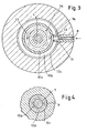
- the strip extends over the entire thickness and viewed in the circumferential direction over a small circular arc portion which in the FIGS. 3 and 4 10b and 10c, outer layers of the extrudate. 10a, the support layer of the extrudate is designated. How the particular FIG. 1 can be seen, the strip 9 is fed downstream of the merging of the layers 10b and 10c and the merger of the annular channels 3b and 3c.
- the flow channel bore 8 extends into a flow divider 11, whose roof-shaped extension 12 above the mouth of the flow channel bore 8 causes a separation of the layers 10b and 10c.
- the recyclate is also not clear.
- the support layer 10 is in turn composed of two melt streams, which are fed from the same extruder.
- the mandrel holder not shown in the figures, for example, provided with two offset by 180 ° heart curve guides for the melt, so that form two tubular streams whose 13 designated confluence points are respectively arranged diametrically opposite and each of overlapping a non-divided melt strand. This gives this layer a high strength on the finished part.
- the distribution of the melt stream is In extrusion heads with mandrel holder (axial sprue heads) unavoidable.
- mandrel holder axial sprue heads
- the creation of an interface when the mandrel or quill flows around the melt is likewise unavoidable.
- the extrusion head 1 is designed as a storage head, in which the annular channel arrangement is part of an annular piston 14, which forms the upper end of a ring storage space 15.
- the FIG. 5 shows the annular piston 14 in the extended state.
- the extrudate emerging from the annular channels 3a, b, c initially enters the ring storage space 15 and there causes a pressure increase, which generates an upward movement of the annular piston 14. If necessary, the annular gap nozzle is closed during this cycle.
- the extruder is conveyed into the ring storage space 15.
Landscapes
- Engineering & Computer Science (AREA)
- Mechanical Engineering (AREA)
- Manufacturing & Machinery (AREA)
- Extrusion Moulding Of Plastics Or The Like (AREA)
- Blow-Moulding Or Thermoforming Of Plastics Or The Like (AREA)
Description
- Die Erfindung betrifft einen Extrusionskopf zur Herstellung eines schlauchförmigen, mehrschichtigen Vorformlings aus erweichtem thermoplastischen Kunststoff mit wenigstens einem in Extrusionsrichtung verlaufenden Sichtstreifen aus transluzentem Material, mit wenigstens zwei Zufuhrwegen für die Zufuhr von plastifiziertem Kunststoff von mehreren Extrudern zu einer Ringkanalanordnung, mit einem sich an die Ringkanalanordnung gegebenenfalls unter Zwischenschaltung eines Ringspeicherraums anschließenden Ringspalt einer Ringspaltdüse und mit wenigstens einer in die Ringkanalanordnung mündenden Fließkanalbohrung zur Einbringung des Sichtstreifens.
- Die Erfindung betrifft weiterhin ein Verfahren zur Extrusion eines schlauchförmigen, mehrschichtigen Vorformlings aus erweichtem thermoplastischen Kunststoff.
- Ein Extrusionskopf der eingangs genannten Art ist beispielsweise aus der
WO 98/08668 - Ein der eingangs genannten Art ähnlicher Extrusionskopf, bei dem aber die Fließkanalbohrung nicht in die Ringkanalanordnung sondern in den darauffolgenden Ringspalt mündet, ist in
EP 0 575 039 A1 offenbart. Diese Druckschrift beschreibt einen Extrusionskopf zur Herstellung mehrerer schlauchförmiger mehrschichtiger Vorformlinge, mit dem nahezu identische Extrudate aus jeder einzelnen Extrusionsstation des Kopfes extrudiert werden können. - Des Weiteren wird ein Extrusionskopf ohne Ringspaltdüse, in
WO 02/085602 A1 - Ganz allgemein ist die Herstellung von Kunststoffbehältern im Extrusionsblasverfahren mit sich in deren Längsrichtung erstreckenden Sichtstreifen bekannt, und zwar sowohl bei einschichtig als auch bei mehrschichtig ausgebildeten Behältern. Bei einschichtig ausgebildeten extrusionsblasgeformten Behältern wird üblicherweise im Extrusionskopf über eine sich quer zur Extrusionsrichtung erstreckende Fließkanalbohrung ein Streifen aus andersfarbigem oder transluzentem Material eingespeist. Diese Einspeisung geht mit einer Auftrennung des Extrudats im Extrusionskopf einher. Stromabwärts der Einspeisestelle vereinigen sich die Teilströme wieder, wobei eine Verschweißung der Schmelze erfolgt.
- Die axial verlaufenden Schweißnähte zwischen den verschiedenen Teilströmen des Extrudats sind Schwachstellen des fertigen Behältnisses, die bei kleinen und leichten Verpackungen durchaus in Kauf genommen werden können.
- Nicht nur bei Kleinbehältnissen ist vielfach eine optische Füllstandskontrolle des Behälterinhaltes wünschenswert. Dies betrifft beispielsweise die sogenannten IBCs (Intermediate Bulk Container) und Fässer.
- Die Kontrolle des Füllstandes des Füllgutes ist dann unproblematisch, wenn diese Behälter aus mehr oder minder durchscheinendem Material hergestellt sind. Oftmals ist es jedoch erforderlich, wie in der
WO 98/08668 - Um auch bei solchen Behältern eine optische Füllstandskontrolle zu gewährleisten, wird in der
WO 98/08668 - Zur Durchführung dieses bekannten Verfahrens wird in der
WO 98/08668 - Die zuvor beschriebene Anordnung ist mit dem Nachteil behaftet, dass eine exakte Festlegung der Schichtgrenze des transluzenten Sichtstreifens in Bezug auf den dreischichtigen Aufbau des Extrudats nicht festlegbar ist. Um zu gewährleisten, dass die transluzente Kunststoffschmelze die beiden äußeren Schichten vollständig durchsetzt, ist es unter Umständen erforderlich, den Strömungskörper in Bezug auf die Längsachse des Extrusionskopfes radial einwärts gerichtet so zu platzieren, dass dieser, wenn auch nur geringfügig, auch von dem Extrudat der inneren Schicht umflossen wird. Dies bedeutet eine Wandstärkenverminderung der inneren in sich geschlossenen Schicht in diesem Bereich, die mit Stabilitätsverlust des Behälters einhergeht.
- Erstreckt sich der Strömungskörper nicht vollständig durch beide äußeren Schichten, leidet darunter die Qualität des Sichtstreifens. Eine Erstreckung des Strömungskörpers exakt in die Trennebene zwischen der inneren und den äußeren Schichten wird kaum möglich bzw. eher zufällig sein. Die vorbeschriebene Ausgestaltung ist insbesondere dann nachteilig, wenn die Dicke der verschiedenen Schichten des Vorformlings verändert oder variiert werden soll. Dann muss jeweils eine Anpassung der Eintauchtiefe des Strömungskörpers erfolgen.
- Der Erfindung liegt daher die Aufgabe zu Grunde, einen Extrusionskopf der eingangs genannten Art bereitzustellen, mit dem diese Nachteile vermieden werden.
- Der Erfindung liegt weiterhin die Aufgabe zu Grunde, ein Extrusionsverfahren bereitzustellen, mit welchem ein mehrschichtiger Vorformling mit Sichtstreifen herstellbar ist, bei dem die Schichtgrenze des Sichtstreifens in Bezug auf die anderen Schichten exakt definierbar ist.
- Die Aufgabe wird zunächst gelöst durch einen Extrusionskopf zur Herstellung eines schlauchförmigen, mehrschichtigen Vorformlings aus erweichtem thermoplastischem Kunststoff mit wenigstens einem in Extrusionsrichtung verlaufenden Sichtstreifen aus transluzentem Material, mit wenigstens zwei Zufuhrwegen für die Zufuhr von plastifiziertem Kunststoff von mehreren Extrudern zu einer Ringkanalanordnung, mit einem sich an die Ringkanalanordnung gegebenenfalls unter Zwischenschaltung eines Ringspeicherraums anschließenden Ringspalt einer Ringspaltdüse und mit wenigstens einer in die Ringkanalanordnung mündenden Fließkanalbohrung zur Einbringung des Sichtstreifens, wobei der Extrusionskopf sich dadurch auszeichnet, dass die Ringkanalanordnung konzentrisch zueinander angeordnete Ringkanäle umfasst, die voneinander getrennte Fließwege für die verschiedenen Schichten des Vorformlings bilden, und dass die Fließkanalbohrung stromaufwärts des Ringspalts und/oder des Ringspeicherraums im Bereich der Trennung der Fließwege in den betreffenden Ringkanal mündet.
- Der Extrusionskopf gemäß der Erfindung bietet den Vorzug, dass sich der Sichtstreifen ohne Beeinträchtigung des die innere Tragschicht bildenden Extrudats so einspeisen lässt, dass er sich über die gesamte Stärke einer oder mehrerer äußerer Schichten erstreckt. Dies wird dadurch gewährleistet, dass die Fließkanalbohrung stromaufwärts des Ringspaltes, in dem die Teilströme des Extrudats zusammengeführt werden, in den Ringkanal mündet. Bei Zusammenführung der Extrudate im Bereich der Düse, d. h. im Bereich des Ringspalts, ist der Sichtstreifen schon in die äußere oder in die äußeren Schichten eingespeist. Vorzugsweise mündet die Fließkanalbohrung über einen Strömungsteiler in den Ringkanal. Der Strömungsteiler erstreckt sich über die gesamte Breite des betreffenden Ringkanals.
- Insbesondere dann, wenn ein im Querschnitt dreischichtig aufgebauter Vorformling extrudiert werden soll, ist es zweckmäßig, wenn der Strömungsteiler in einem äußeren Ringkanal angeordnet ist, und zwar derart, dass er eine vollständige Aufteilung des diesen Ringkanal durchfließenden Extrudats in axialer Richtung bewirkt.
- Bei einer bevorzugten Ausführungsform der Erfindung münden die Ringkanäle unmittelbar in den Ringspalt der Ringspaltdüse.
- Alternativ kann vorgesehen sein, dass dem Ringspalt ein Ringspeicherraum vorgeschaltet ist und dass die Ringkanalanordnung als Teil eines Ringkolbens ausgebildet ist.
- Mit anderen Worten, der Extrusionskopf kann als Speicherkopf zur diskontinuierlichen Extrusion als auch als Extrusionskopf zur kontinuierlichen Extrusion ausgebildet sein.
- Die Ringkanalanordnung kann wenigstens drei Ringkanäle umfassen, nämlich einen inneren und zwei äußere, wobei die äußeren Ringkanäle stromaufwärts der Mündung des inneren Ringkanals in der Ringspaltdüse zusammengeführt sind.
- Die der Erfindung zu Grunde liegende Aufgabe wird weiterhin durch ein Verfahren zur Extrusion eines schlauchförmigen, mehrschichtigen Vorformlings aus erweichtem thermoplastischem Kunststoff mit wenigstens einem in Extrusionsrichtung verlaufenden Streifen aus andersartigem Kunststoff gelöst, wobei in einem Extrusionskopf mehrere Schichten des Kunststoffs über einen Teil des Extrusionswegs konzentrisch zueinander über voneinander getrennte Fließwege geführt werden und wobei der Streifen in eine äußere Schicht stromaufwärts der Zusammenführung der coextrudierten Teilströme eingespeist wird.
- Vorzugsweise wird als Streifen andersartigen Materials ein Sichtstreifen aus transluzentem Kunststoff eingespeist. Unter transluzent im Sinne der Erfindung können sowohl schwach durchscheinend als auch klarsichtige Materialien zu verstehen sein.
- Bei der bevorzugten Variante des erfindungsgemäßen Verfahrens werden eine innere Tragschicht und zwei äußere Deckschichten coextrudiert, wobei der Streifen so eingespeist wird, dass er nur die Deckschichten zumindest teilweise durchsetzt. Zumindest teilweise im Sinne der Erfindung heißt, dass beispielsweise bei mehreren Deckschichten nur diejenige von dem Sichtstreifen durchsetzt wird, die eingefärbt ist, d. h. die äußerste.
- Die Erfindung wird nachstehend anhand eines in den Zeichnungen dargestellten Ausführungsbeispiels erläutert.
- Es zeigen:
- Figur 1
- den Extrusionskopf gemäß der Erfindung, teilweise im Schnitt,
- Figur 2
- eine perspektivische Ansicht des Strömungsteilers,
- Figur 3
- einen Schnitt durch den Extrusionskopf entlang der Linie III-III in
Figur 1 , - Figur 4
- einen Schnitt durch den Extrusionskopf entlang der Linien IV-IV in
Figur 1 und - Figur 5
- einen Schnitt durch einen Extrusionskopf gemäß einem zweiten Ausführungsbeispiel der Erfindung.
-
Figur 1 zeigt eine teilweise geschnittene Teilansicht des Extrusionskopfes 1 gemäß der Erfindung. Dieser besteht in bekannter Art und Weise aus einem Gehäuse 2, einer in dem Gehäuse ausgebildeten Ringkanalanordnung, umfassend einen inneren Ringkanal 3a und zwei äußere Ringkanäle 3b und 3c, die jeweils aus verschiedenen, nicht dargestellten Extrudern gespeist werden, einem Dorn 4 mit Düsenpilz 5 sowie einem Düsenmantel 6, der mit dem Düsenpilz 5 zusammen einen verstellbaren Ringspalt 7 bildet. Der Dorn 4 ist axial verstellbar, mit diesem auch der Düsenpilz 5 innerhalb des Düsenmantels 6, wodurch letztendlich die Spaltbreite des Ringspaltes 7 in dem sich konisch erweiternden Düsenbereich während der Extrusion nach einem vorgegebenen Wanddickenprogramm einstellbar ist. - Die Fließwege des durch den Extrusionskopf 1 hindurchtretenden erweichten Extrudats sind in
Figur 1 mit Pfeilen dargestellt. In Fließrichtung des Extrudats betrachtet werden zunächst die Ringkanäle 3b und 3c zusammengeführt, weiter stromabwärts bei Eintritt in den Ringspalt 7 werden dann die vereinigten Teilströme 3b, 3c einerseits und der Teilstrom 3a zusammengeführt. Durch den Ringkanal 3a wird das die innere Tragschicht des Vorformlings bildende Extrudat geführt. - In den Ringkanal 3b mündet eine sich quer zur Extrusionsrichtung erstreckende Fließkanalbohrung 8, über die ein transluzenter Kunststoffstreifen in den Ringkanal 3b stromabwärts der Mündung des Ringkanals 3c eingespeist wird. Der Streifen erstreckt sich über die gesamte Dicke und in Umfangsrichtung betrachtet über einen kleinen Kreisbogenabschnitt, der in den
Figuren 3 und 4 mit 10b und 10c bezeichneten äußeren Schichten des Extrudats. Mit 10a ist die Tragschicht des Extrudats bezeichnet. Wie insbesondere derFigur 1 zu entnehmen ist, wird der Streifen 9 stromabwärts der Zusammenführung der Schichten 10b und 10c bzw. der Zusammenführung der Ringkanäle 3b und 3c eingespeist. - Die Fließkanalbohrung 8 erstreckt sich in einen Strömungsteiler 11, dessen dachförmiger Fortsatz 12 oberhalb der Mündung der Fließkanalbohrung 8 eine Auftrennung der Schichten 10b und 10c bewirkt.
- Bei dem dargestellten Ausführungsbeispiel besteht die Tragschicht 10a aus nicht eingefärbtem Kunststoff, die Schicht 10b aus einem Rezyclat, d. h. aus aufbereitetem Butzenmaterial und die Schicht 10c aus einem beispielsweise mit Ruß gefüllten und somit eingefärbten Kunststoff. Das Rezyklat ist ebenfalls nicht klarsichtig.
- Wie in den
Figuren 3 und 4 andeutungsweise dargestellt ist, ist die Tragschicht 10 ihrerseits aus zwei Schmelzeströmen zusammengesetzt, die jedoch aus dem gleichen Extruder gespeist werden. Dies ergibt sich daraus, dass der in den Figuren nicht dargestellte Dornhalter beispielsweise mit zwei um 180° versetzten herzkurvenförmigen Führungen für die Schmelze versehen ist, so dass sich zwei schlauchartige Ströme bilden, deren mit 13 bezeichneten Zusammenflussstellen jeweils diametral gegenüberliegend angeordnet sind und die jeweils von einem nicht aufgeteilten Schmelzestrang überlappt werden. Dies verleiht dieser Schicht eine hohe Festigkeit am Fertigteil. - Wie dem Fachmann bekannt ist, ist die Aufteilung des Schmelzestroms bei Extrusionsköpfen mit Dornhalter (Axial-Angussköpfen) nicht vermeidbar. Bei Radial-Angussköpfen ist ebenfalls die Erzeugung einer Nahtstelle bei Umfließen des Dorns oder der Pinole durch die Schmelze unvermeidbar.
- Bei dem in
Figur 5 dargestellten Ausführungsbeispiel der Erfindung ist der Extrusionskopf 1 als Speicherkopf ausgebildet, bei dem die Ringkanalanordnung Teil eines Ringkolbens 14 ist, der den oberen Abschluss eines Ringspeicherraums 15 bildet. DieFigur 5 zeigt den Ringkolben 14 im ausgefahrenen Zustand. Das aus den Ringkanälen 3a, b, c austretende Extrudat tritt zunächst in den Ringspeicherraum 15 ein und bewirkt dort eine Druckerhöhung, die eine Aufwärtsbewegung des Ringkolbens 14 erzeugt. Während dieses Zyklus ist erforderlichenfalls die Ringspaltdüse geschlossen. Der Extruder fördert in den Ringspeicherraum 15. Ist der Ringspeicherraum 15 gefüllt, wird über eine Axialverschiebung des Ringkolbens 14 der Ringspeicherraum 15 bei geöffneter Extrusionsdüse aktiv entleert, wobei währenddessen die Extruder weiterbetrieben werden. Diese Vorgänge sind hinlänglich bekannt und sind hier nur der Vollständigkeit halber beschrieben. Weiterhin sind bei dem inFigur 5 dargestellten Ausführungsbeispiel zwei diametral gegenüberliegend angeordnete Fließkanalbohrungen 8 zur Erzeugung zweier Streifen 9 vorgesehen. Im Übrigen sind bei dem inFigur 5 dargestellten Ausführungsbeispiel dem ersten Ausführungsbeispiel entsprechende Bauteile mit gleichen Bezugszeichen versehen. -
- 1
- Extrusionskopf
- 2
- Gehause
- 3a, b, c
- Ringkanäle
- 4
- Dorn
- 5
- Dusenpilz
- 6
- Dusenmantel
- 7
- Ringspalt
- 8
- Fließkanalbohrung
- 9
- Streifen
- 10b, c
- außere Schichten
- 10a
- Tragschicht
- 11
- Stromungsteiler
- 12
- Fortsatz
- 13
- Zusammenflussstellen
- 14
- Ringkolben
- 15
- Ringspeicherraum
Claims (11)
- Extrusionskopf zur Herstellung eines schlauchförmigen, mehrschichtigen Vorformlings aus erweichtem thermoplastischen Kunststoff mit wenigstens einem in Extrusionsrichtung verlaufenden Sichtstreifen aus transluzentem Material, mit wenigstens zwei Zufuhrwegen für die Zufuhr von plastifiziertem Kunststoff von mehreren Extrudern zu einer Ringkanalanordnung, mit einem sich an die Ringkanalanordnung gegebenenfalls unter Zwischenschaltung eines Ringspeicherraums anschließenden Ringspalt einer Ringspaltdüse und mit wenigstens einer in die Ringkanalanordnung mündenden Fliesskanalbohrung zur Einbringung des Sichtstreifens, wobei die Ringkanalanordnung konzentrisch zueinander angeordnete Ringkanäle (3a, b, c) umfasst, die voneinander getrennte Fliesswege für die verschiedenen Schichten (10a, b, c) des Vorformlings bilden, dadurch gekennzeichnet, dass die Fliesskanalbohrung (8) stromaufwärts des Ringspalts (7) und/oder eines Ringspeicherraums (15) im Bereich der Trennung der Fliesswege in den betreffenden Ringkanal (3b) mündet.
- Extrusionskopf nach Anspruch 1, dadurch gekennzeichnet, dass die Fliesskanalbohrung (8) über einen Strömungsteiler (11) in den Ringkanal (3b) mündet.
- Extrusionskopf nach Anspruch 2, dadurch gekennzeichnet, dass der Strömungsteiler (11) in einem äußeren Ringkanal (3b) angeordnet ist und zwar derart, dass er eine vollständige Aufteilung des diesen Ringkanal durchfließenden Extrudats in axialer Richtung bewirkt.
- Extrusionskopf nach einem der Ansprüche 1 bis 3, dadurch gekennzeichnet, dass die Ringkanäle (3a, b, c) unmittelbar in den Ringspalt (7) der Ringspaltdüse münden.
- Extrusionskopf nach einem der Ansprüche 1 bis 3, dadurch gekennzeichnet, dass dem Ringspalt (7) ein Ringspeicherraum (15) vorgeschaltet ist und dass die Ringkanalanordnung als Teil eines Ringkolbens (14) ausgebildet ist.
- Extrusionskopf nach einem der Ansprüche 1 bis 5, dadurch gekennzeichnet, dass die Ringkanalanordnung drei Ringkanäle (3a, b, c) umfasst, nämlich einen inneren (3a) und zwei äußere (3b, c), wobei die äußeren Ringkanäle (3b, c) stromaufwärts der Mündung des inneren Ringkanals (3a) in die Ringspaltdüse zusammengeführt sind.
- Verfahren zur Extrusion eines schlauchförmigen, mehrschichtigen Vorformlings aus erweichtem thermoplastischen Kunststoff mit wenigstens einem in Extrusionsrichtung verlaufenden Streifen aus andersartigem Kunststoff, wobei in einem eine Ringspaltdüse aufweisenden Extrusionskopf mehrere Schichten des Kunststoffs über einen Teil des Extrusionsweges konzentrisch zueinander über voneinander getrennte Fliesswege geführt werden und dadurch gekennzeichnet, dass der Streifen in eine äußere Schicht stromaufwärts der Zusammenführung der coextrudierten Teilströme eingespeist wird.
- Verfahren nach Anspruch 7, dadurch gekennzeichnet, dass als Streifen andersartigen Materials ein Sichtstreifen aus transluzentem Kunststoff eingespeist wird.
- Verfahren nach einem der Ansprüche 7 oder 8, dadurch gekennzeichnet, dass eine innere Tragschicht (10a) und zwei äußere Deckschichten (10b, c) coextrudiert werden und dass der Streifen (9) so eingespeist wird, dass er nur die Deckschichten (10b, c) zumindest teilweise durchsetzt.
- Verfahren nach einem der Ansprüche 7 bis 9, dadurch gekennzeichnet, dass der Vorformling kontinuierlich extrudiert wird.
- Verfahren nach einem der Ansprüche 7 bis 9, dadurch gekennzeichnet, dass der Vorformling diskontinuierlich extrudiert wird.
Applications Claiming Priority (2)
| Application Number | Priority Date | Filing Date | Title |
|---|---|---|---|
| DE10312522 | 2003-03-20 | ||
| DE10312522A DE10312522B3 (de) | 2003-03-20 | 2003-03-20 | Extrusionskopf sowie Extrusionsverfahren |
Publications (2)
| Publication Number | Publication Date |
|---|---|
| EP1459866A1 EP1459866A1 (de) | 2004-09-22 |
| EP1459866B1 true EP1459866B1 (de) | 2013-04-17 |
Family
ID=32798003
Family Applications (1)
| Application Number | Title | Priority Date | Filing Date |
|---|---|---|---|
| EP04002867.2A Expired - Lifetime EP1459866B1 (de) | 2003-03-20 | 2004-02-10 | Extrusionskopf sowie Extrusionsverfahren |
Country Status (5)
| Country | Link |
|---|---|
| US (1) | US7374412B2 (de) |
| EP (1) | EP1459866B1 (de) |
| DE (1) | DE10312522B3 (de) |
| ES (1) | ES2419162T3 (de) |
| PT (1) | PT1459866E (de) |
Cited By (1)
| Publication number | Priority date | Publication date | Assignee | Title |
|---|---|---|---|---|
| CN103538236A (zh) * | 2012-07-16 | 2014-01-29 | 宁波康润机械科技有限公司 | 塑料管材挤出模具 |
Families Citing this family (6)
| Publication number | Priority date | Publication date | Assignee | Title |
|---|---|---|---|---|
| CA2622692C (en) * | 2007-02-26 | 2015-10-06 | Advanced Drainage Systems, Inc. | Defined ratio dual-wall pipe die |
| DE202007013318U1 (de) * | 2007-09-21 | 2008-01-03 | Mauser-Werke Gmbh | Vorrichtung und deren Verwendung zur Herstellung von Kunststoff-Behältern mit Sichtstreifen |
| US10913194B2 (en) * | 2016-04-06 | 2021-02-09 | Graham Engineering Corporation | Device and method for continuously extruding tubing having different materials |
| DE102017105807B3 (de) | 2017-03-17 | 2018-08-16 | Schlemmer Holding GmbH | Mehrkomponenten-Extrusionsspritzkopf, Mehrkomponenten-Extrusionsanlage und Verfahren zum Herstellen eines Verbundschlauchs |
| CN109352953B (zh) * | 2018-10-31 | 2021-01-29 | 徐州耐克盾机械制造有限公司 | 一种多层吹塑机模头 |
| CN117818009B (zh) * | 2024-02-22 | 2024-08-20 | 河北鑫鹏通信设备有限公司 | 基于端口结构便于拆卸的pe管材加工模具 |
Family Cites Families (11)
| Publication number | Priority date | Publication date | Assignee | Title |
|---|---|---|---|---|
| JPS5814294B2 (ja) * | 1976-04-26 | 1983-03-18 | 呉羽化学工業株式会社 | 合成樹脂複合管状体の成形方法及びダイ構造 |
| US4802833A (en) * | 1988-03-21 | 1989-02-07 | Hoover Universal, Inc. | Accumulator head for producing a storage drum with view stripe |
| US4890994A (en) * | 1988-09-30 | 1990-01-02 | Hoover University, Inc. | Apparatus for forming a parison with a view stripe |
| US4874305A (en) * | 1988-11-03 | 1989-10-17 | Somerset Technologies, Inc. | Accumulator extrusion head for producing striped parisons |
| US5204120A (en) * | 1989-10-31 | 1993-04-20 | Hoover Universal, Inc. | Intermittent multi-layer multi-parison extrusion head |
| AU636417B2 (en) * | 1990-12-11 | 1993-04-29 | Hoover Universal Inc. | Die head for multiple resin tubular plastic body |
| US5460772A (en) * | 1991-12-27 | 1995-10-24 | Nippon Steel Chemical Co., Ltd. | Process for multilayer blow molding |
| US5221540A (en) * | 1992-06-17 | 1993-06-22 | Hoover Universal, Inc. | Extrusion head with adjustable view stripe positioning |
| US5464107A (en) * | 1993-06-25 | 1995-11-07 | Owens-Illinois Plastic Products Inc. | Hollow plastic container with viewing stripe and method of making |
| DE19635334A1 (de) * | 1996-08-31 | 1998-03-05 | Guenter Dipl Ing Richter | Faßartiger Behälter aus Kunststoff sowie Verfahren und Vorrichtung zu seiner Herstellung |
| EP1420934A1 (de) | 2001-04-20 | 2004-05-26 | ISPA, Inc. | Extrusionsformverfahren |
-
2003
- 2003-03-20 DE DE10312522A patent/DE10312522B3/de not_active Expired - Fee Related
-
2004
- 2004-02-10 PT PT4002867T patent/PT1459866E/pt unknown
- 2004-02-10 EP EP04002867.2A patent/EP1459866B1/de not_active Expired - Lifetime
- 2004-02-10 ES ES04002867T patent/ES2419162T3/es not_active Expired - Lifetime
- 2004-03-22 US US10/805,782 patent/US7374412B2/en not_active Expired - Lifetime
Cited By (1)
| Publication number | Priority date | Publication date | Assignee | Title |
|---|---|---|---|---|
| CN103538236A (zh) * | 2012-07-16 | 2014-01-29 | 宁波康润机械科技有限公司 | 塑料管材挤出模具 |
Also Published As
| Publication number | Publication date |
|---|---|
| PT1459866E (pt) | 2013-07-23 |
| DE10312522B3 (de) | 2004-09-23 |
| EP1459866A1 (de) | 2004-09-22 |
| ES2419162T3 (es) | 2013-08-19 |
| US20040183224A1 (en) | 2004-09-23 |
| US7374412B2 (en) | 2008-05-20 |
Similar Documents
| Publication | Publication Date | Title |
|---|---|---|
| EP0494273B1 (de) | Speicherkopf für eine blasformmaschine | |
| EP0326584B1 (de) | Verfahren und vorrichtung zur herstellung grossvolumiger hohlkörper aus kunststoff mit mehrschichtigen wandungen | |
| DE2100192C3 (de) | Strangpreßkopf zum Herstellen eines Hohlstranges | |
| DE69518652T2 (de) | Mehrschichtiger behälter | |
| EP0249866B1 (de) | Speicherkopf für die Herstellung mehrschichtiger coextrudierter Schläuche aus Kunststoff | |
| EP0907493B1 (de) | Kunststofftubenkörper und verfahren zu deren herstellung | |
| DE2718537C3 (de) | Extrudiereinrichtung zum Herstellen eines aus wenigstens zwei Schichten bestehenden Verbundrohres aus thermoplastischen Kunsts | |
| DE2536851C2 (de) | Strangpreßkopf zum Herstellen eines mehrschichtigen, durch Blasformen weiterverarbeitbaren schlauchförmigen Rohlings aus thermoplastischen Kunststoffen | |
| EP0380015B1 (de) | Verfahren und Vorrichtung zur diskontinuierlichen Herstellung mehrschichtiger, coextrudierter, schlauchartiger Vorformlinge aus thermoplastischem Kunststoff | |
| DE2712971A1 (de) | Schlauchkopf | |
| DE3623308C2 (de) | ||
| EP0349872B1 (de) | Verfahren und Vorrichtung zum Herstellen von Hohlkörpern aus thermoplastischen Kunstoffen | |
| DE19959482C2 (de) | Extrusionskopf für das Blasformen von Hohlkörpern aus thermoplastischem Kunststoff | |
| EP2709822B1 (de) | Verfahren zur kalibrierung einer ausgiessöffnung eines im extrusionsblasverfahren hergestellten kunststoffbehälters | |
| DE10312522B3 (de) | Extrusionskopf sowie Extrusionsverfahren | |
| EP0923445B1 (de) | Fassartiger behälter aus kunststoff sowie verfahren und vorrichtung zu seiner herstellung | |
| DE69218610T2 (de) | Speicherkopf für extrusions-blasformmaschine | |
| DE2712910A1 (de) | Schlauchkopf | |
| DE2911833C3 (de) | Gerader Spritzkopf zum Extrudieren zweier zueinander konzentrischer Kunststoffrohre | |
| EP2225083B1 (de) | Verfahren zur herstellung eines vorformlings sowie die verwendung des verfahrens | |
| DE102021118705A1 (de) | Vorrichtung und Verfahren für die biaxiale Kunststoff-Extrusion | |
| EP1498254B1 (de) | Extrusionskopf | |
| DE3704698A1 (de) | Coextrusionskopf | |
| DE3516470A1 (de) | Verfahren und vorrichtung zur herstellung blasgeformter hohlkoerper aus thermoplastischen kunststoffen | |
| DE19643224C1 (de) | Verteiler für einen Extrusionskopf zur Herstellung von schlauchförmigen Vorformlingen aus extrudierbarem Kunststoff |
Legal Events
| Date | Code | Title | Description |
|---|---|---|---|
| PUAI | Public reference made under article 153(3) epc to a published international application that has entered the european phase |
Free format text: ORIGINAL CODE: 0009012 |
|
| AK | Designated contracting states |
Kind code of ref document: A1 Designated state(s): AT BE BG CH CY CZ DE DK EE ES FI FR GB GR HU IE IT LI LU MC NL PT RO SE SI SK TR |
|
| AX | Request for extension of the european patent |
Extension state: AL LT LV MK |
|
| RAP1 | Party data changed (applicant data changed or rights of an application transferred) |
Owner name: KAUTEX MASCHINENBAU GMBH |
|
| 17P | Request for examination filed |
Effective date: 20050209 |
|
| AKX | Designation fees paid |
Designated state(s): AT BE BG CH CY CZ DE DK EE ES FI FR GB GR HU IE IT LI LU MC NL PT RO SE SI SK TR |
|
| 17Q | First examination report despatched |
Effective date: 20090415 |
|
| GRAP | Despatch of communication of intention to grant a patent |
Free format text: ORIGINAL CODE: EPIDOSNIGR1 |
|
| GRAS | Grant fee paid |
Free format text: ORIGINAL CODE: EPIDOSNIGR3 |
|
| GRAA | (expected) grant |
Free format text: ORIGINAL CODE: 0009210 |
|
| AK | Designated contracting states |
Kind code of ref document: B1 Designated state(s): AT BE BG CH CY CZ DE DK EE ES FI FR GB GR HU IE IT LI LU MC NL PT RO SE SI SK TR |
|
| REG | Reference to a national code |
Ref country code: GB Ref legal event code: FG4D Free format text: NOT ENGLISH |
|
| REG | Reference to a national code |
Ref country code: CH Ref legal event code: EP |
|
| REG | Reference to a national code |
Ref country code: IE Ref legal event code: FG4D Free format text: LANGUAGE OF EP DOCUMENT: GERMAN |
|
| REG | Reference to a national code |
Ref country code: AT Ref legal event code: REF Ref document number: 606972 Country of ref document: AT Kind code of ref document: T Effective date: 20130515 |
|
| REG | Reference to a national code |
Ref country code: DE Ref legal event code: R096 Ref document number: 502004014115 Country of ref document: DE Effective date: 20130606 |
|
| REG | Reference to a national code |
Ref country code: PT Ref legal event code: SC4A Free format text: AVAILABILITY OF NATIONAL TRANSLATION Effective date: 20130716 |
|
| REG | Reference to a national code |
Ref country code: ES Ref legal event code: FG2A Ref document number: 2419162 Country of ref document: ES Kind code of ref document: T3 Effective date: 20130819 |
|
| REG | Reference to a national code |
Ref country code: NL Ref legal event code: T3 |
|
| PG25 | Lapsed in a contracting state [announced via postgrant information from national office to epo] |
Ref country code: GR Free format text: LAPSE BECAUSE OF FAILURE TO SUBMIT A TRANSLATION OF THE DESCRIPTION OR TO PAY THE FEE WITHIN THE PRESCRIBED TIME-LIMIT Effective date: 20130718 Ref country code: SI Free format text: LAPSE BECAUSE OF FAILURE TO SUBMIT A TRANSLATION OF THE DESCRIPTION OR TO PAY THE FEE WITHIN THE PRESCRIBED TIME-LIMIT Effective date: 20130417 Ref country code: SE Free format text: LAPSE BECAUSE OF FAILURE TO SUBMIT A TRANSLATION OF THE DESCRIPTION OR TO PAY THE FEE WITHIN THE PRESCRIBED TIME-LIMIT Effective date: 20130417 |
|
| PG25 | Lapsed in a contracting state [announced via postgrant information from national office to epo] |
Ref country code: CY Free format text: LAPSE BECAUSE OF FAILURE TO SUBMIT A TRANSLATION OF THE DESCRIPTION OR TO PAY THE FEE WITHIN THE PRESCRIBED TIME-LIMIT Effective date: 20130417 Ref country code: BG Free format text: LAPSE BECAUSE OF FAILURE TO SUBMIT A TRANSLATION OF THE DESCRIPTION OR TO PAY THE FEE WITHIN THE PRESCRIBED TIME-LIMIT Effective date: 20130717 |
|
| PG25 | Lapsed in a contracting state [announced via postgrant information from national office to epo] |
Ref country code: DK Free format text: LAPSE BECAUSE OF FAILURE TO SUBMIT A TRANSLATION OF THE DESCRIPTION OR TO PAY THE FEE WITHIN THE PRESCRIBED TIME-LIMIT Effective date: 20130417 Ref country code: EE Free format text: LAPSE BECAUSE OF FAILURE TO SUBMIT A TRANSLATION OF THE DESCRIPTION OR TO PAY THE FEE WITHIN THE PRESCRIBED TIME-LIMIT Effective date: 20130417 Ref country code: SK Free format text: LAPSE BECAUSE OF FAILURE TO SUBMIT A TRANSLATION OF THE DESCRIPTION OR TO PAY THE FEE WITHIN THE PRESCRIBED TIME-LIMIT Effective date: 20130417 |
|
| PLBE | No opposition filed within time limit |
Free format text: ORIGINAL CODE: 0009261 |
|
| STAA | Information on the status of an ep patent application or granted ep patent |
Free format text: STATUS: NO OPPOSITION FILED WITHIN TIME LIMIT |
|
| PG25 | Lapsed in a contracting state [announced via postgrant information from national office to epo] |
Ref country code: RO Free format text: LAPSE BECAUSE OF FAILURE TO SUBMIT A TRANSLATION OF THE DESCRIPTION OR TO PAY THE FEE WITHIN THE PRESCRIBED TIME-LIMIT Effective date: 20130417 |
|
| 26N | No opposition filed |
Effective date: 20140120 |
|
| REG | Reference to a national code |
Ref country code: DE Ref legal event code: R097 Ref document number: 502004014115 Country of ref document: DE Effective date: 20140120 |
|
| REG | Reference to a national code |
Ref country code: DE Ref legal event code: R082 Ref document number: 502004014115 Country of ref document: DE Representative=s name: KIERDORF RITSCHEL PATENTANWAELTE PARTG MBB, DE Ref country code: DE Ref legal event code: R082 Ref document number: 502004014115 Country of ref document: DE Representative=s name: KIERDORF RITSCHEL RICHLY PATENTANWAELTE PARTG , DE Ref country code: DE Ref legal event code: R082 Ref document number: 502004014115 Country of ref document: DE Representative=s name: RICHLY & RITSCHEL PATENTANWAELTE PARTG MBB, DE |
|
| PG25 | Lapsed in a contracting state [announced via postgrant information from national office to epo] |
Ref country code: MC Free format text: LAPSE BECAUSE OF FAILURE TO SUBMIT A TRANSLATION OF THE DESCRIPTION OR TO PAY THE FEE WITHIN THE PRESCRIBED TIME-LIMIT Effective date: 20130417 Ref country code: LU Free format text: LAPSE BECAUSE OF FAILURE TO SUBMIT A TRANSLATION OF THE DESCRIPTION OR TO PAY THE FEE WITHIN THE PRESCRIBED TIME-LIMIT Effective date: 20140210 |
|
| REG | Reference to a national code |
Ref country code: CH Ref legal event code: PL |
|
| PG25 | Lapsed in a contracting state [announced via postgrant information from national office to epo] |
Ref country code: CH Free format text: LAPSE BECAUSE OF NON-PAYMENT OF DUE FEES Effective date: 20140228 Ref country code: LI Free format text: LAPSE BECAUSE OF NON-PAYMENT OF DUE FEES Effective date: 20140228 |
|
| REG | Reference to a national code |
Ref country code: IE Ref legal event code: MM4A |
|
| PG25 | Lapsed in a contracting state [announced via postgrant information from national office to epo] |
Ref country code: IE Free format text: LAPSE BECAUSE OF NON-PAYMENT OF DUE FEES Effective date: 20140210 |
|
| REG | Reference to a national code |
Ref country code: FR Ref legal event code: PLFP Year of fee payment: 12 |
|
| REG | Reference to a national code |
Ref country code: FR Ref legal event code: PLFP Year of fee payment: 13 |
|
| PG25 | Lapsed in a contracting state [announced via postgrant information from national office to epo] |
Ref country code: HU Free format text: LAPSE BECAUSE OF FAILURE TO SUBMIT A TRANSLATION OF THE DESCRIPTION OR TO PAY THE FEE WITHIN THE PRESCRIBED TIME-LIMIT; INVALID AB INITIO Effective date: 20040210 |
|
| REG | Reference to a national code |
Ref country code: FR Ref legal event code: PLFP Year of fee payment: 14 |
|
| REG | Reference to a national code |
Ref country code: FR Ref legal event code: PLFP Year of fee payment: 15 |
|
| REG | Reference to a national code |
Ref country code: DE Ref legal event code: R079 Ref document number: 502004014115 Country of ref document: DE Free format text: PREVIOUS MAIN CLASS: B29C0047040000 Ipc: B29C0048160000 |
|
| PGFP | Annual fee paid to national office [announced via postgrant information from national office to epo] |
Ref country code: GB Payment date: 20220221 Year of fee payment: 19 Ref country code: FI Payment date: 20220215 Year of fee payment: 19 Ref country code: DE Payment date: 20220216 Year of fee payment: 19 Ref country code: AT Payment date: 20220215 Year of fee payment: 19 |
|
| PGFP | Annual fee paid to national office [announced via postgrant information from national office to epo] |
Ref country code: TR Payment date: 20220128 Year of fee payment: 19 Ref country code: PT Payment date: 20220203 Year of fee payment: 19 Ref country code: NL Payment date: 20220216 Year of fee payment: 19 Ref country code: IT Payment date: 20220228 Year of fee payment: 19 Ref country code: FR Payment date: 20220221 Year of fee payment: 19 Ref country code: ES Payment date: 20220318 Year of fee payment: 19 Ref country code: CZ Payment date: 20220201 Year of fee payment: 19 Ref country code: BE Payment date: 20220216 Year of fee payment: 19 |
|
| REG | Reference to a national code |
Ref country code: DE Ref legal event code: R119 Ref document number: 502004014115 Country of ref document: DE |
|
| REG | Reference to a national code |
Ref country code: NL Ref legal event code: MM Effective date: 20230301 |
|
| REG | Reference to a national code |
Ref country code: AT Ref legal event code: MM01 Ref document number: 606972 Country of ref document: AT Kind code of ref document: T Effective date: 20230210 |
|
| REG | Reference to a national code |
Ref country code: BE Ref legal event code: MM Effective date: 20230228 |
|
| GBPC | Gb: european patent ceased through non-payment of renewal fee |
Effective date: 20230210 |
|
| PG25 | Lapsed in a contracting state [announced via postgrant information from national office to epo] |
Ref country code: PT Free format text: LAPSE BECAUSE OF NON-PAYMENT OF DUE FEES Effective date: 20230810 Ref country code: FI Free format text: LAPSE BECAUSE OF NON-PAYMENT OF DUE FEES Effective date: 20230210 Ref country code: CZ Free format text: LAPSE BECAUSE OF NON-PAYMENT OF DUE FEES Effective date: 20230210 Ref country code: AT Free format text: LAPSE BECAUSE OF NON-PAYMENT OF DUE FEES Effective date: 20230210 |
|
| PG25 | Lapsed in a contracting state [announced via postgrant information from national office to epo] |
Ref country code: NL Free format text: LAPSE BECAUSE OF NON-PAYMENT OF DUE FEES Effective date: 20230301 |
|
| PG25 | Lapsed in a contracting state [announced via postgrant information from national office to epo] |
Ref country code: GB Free format text: LAPSE BECAUSE OF NON-PAYMENT OF DUE FEES Effective date: 20230210 |
|
| PG25 | Lapsed in a contracting state [announced via postgrant information from national office to epo] |
Ref country code: IT Free format text: LAPSE BECAUSE OF NON-PAYMENT OF DUE FEES Effective date: 20230210 Ref country code: GB Free format text: LAPSE BECAUSE OF NON-PAYMENT OF DUE FEES Effective date: 20230210 Ref country code: FR Free format text: LAPSE BECAUSE OF NON-PAYMENT OF DUE FEES Effective date: 20230228 Ref country code: DE Free format text: LAPSE BECAUSE OF NON-PAYMENT OF DUE FEES Effective date: 20230901 |
|
| PG25 | Lapsed in a contracting state [announced via postgrant information from national office to epo] |
Ref country code: BE Free format text: LAPSE BECAUSE OF NON-PAYMENT OF DUE FEES Effective date: 20230228 |
|
| REG | Reference to a national code |
Ref country code: ES Ref legal event code: FD2A Effective date: 20240402 |
|
| PG25 | Lapsed in a contracting state [announced via postgrant information from national office to epo] |
Ref country code: ES Free format text: LAPSE BECAUSE OF NON-PAYMENT OF DUE FEES Effective date: 20230211 |
|
| PG25 | Lapsed in a contracting state [announced via postgrant information from national office to epo] |
Ref country code: ES Free format text: LAPSE BECAUSE OF NON-PAYMENT OF DUE FEES Effective date: 20230211 Ref country code: PT Free format text: LAPSE BECAUSE OF EXPIRATION OF PROTECTION Effective date: 20240221 |
|
| PG25 | Lapsed in a contracting state [announced via postgrant information from national office to epo] |
Ref country code: PT Free format text: LAPSE BECAUSE OF NON-PAYMENT OF DUE FEES Effective date: 20230210 |