EP1457932A2 - Passive keyless entry system for vehicle - Google Patents
Passive keyless entry system for vehicle Download PDFInfo
- Publication number
- EP1457932A2 EP1457932A2 EP04004855A EP04004855A EP1457932A2 EP 1457932 A2 EP1457932 A2 EP 1457932A2 EP 04004855 A EP04004855 A EP 04004855A EP 04004855 A EP04004855 A EP 04004855A EP 1457932 A2 EP1457932 A2 EP 1457932A2
- Authority
- EP
- European Patent Office
- Prior art keywords
- vehicle
- outside handle
- door
- switch
- portable unit
- Prior art date
- Legal status (The legal status is an assumption and is not a legal conclusion. Google has not performed a legal analysis and makes no representation as to the accuracy of the status listed.)
- Withdrawn
Links
Images

Classifications
-
- G—PHYSICS
- G07—CHECKING-DEVICES
- G07C—TIME OR ATTENDANCE REGISTERS; REGISTERING OR INDICATING THE WORKING OF MACHINES; GENERATING RANDOM NUMBERS; VOTING OR LOTTERY APPARATUS; ARRANGEMENTS, SYSTEMS OR APPARATUS FOR CHECKING NOT PROVIDED FOR ELSEWHERE
- G07C9/00—Individual registration on entry or exit
- G07C9/00174—Electronically operated locks; Circuits therefor; Nonmechanical keys therefor, e.g. passive or active electrical keys or other data carriers without mechanical keys
- G07C9/00309—Electronically operated locks; Circuits therefor; Nonmechanical keys therefor, e.g. passive or active electrical keys or other data carriers without mechanical keys operated with bidirectional data transmission between data carrier and locks
-
- G—PHYSICS
- G07—CHECKING-DEVICES
- G07C—TIME OR ATTENDANCE REGISTERS; REGISTERING OR INDICATING THE WORKING OF MACHINES; GENERATING RANDOM NUMBERS; VOTING OR LOTTERY APPARATUS; ARRANGEMENTS, SYSTEMS OR APPARATUS FOR CHECKING NOT PROVIDED FOR ELSEWHERE
- G07C9/00—Individual registration on entry or exit
- G07C9/00174—Electronically operated locks; Circuits therefor; Nonmechanical keys therefor, e.g. passive or active electrical keys or other data carriers without mechanical keys
- G07C9/00309—Electronically operated locks; Circuits therefor; Nonmechanical keys therefor, e.g. passive or active electrical keys or other data carriers without mechanical keys operated with bidirectional data transmission between data carrier and locks
- G07C2009/00388—Electronically operated locks; Circuits therefor; Nonmechanical keys therefor, e.g. passive or active electrical keys or other data carriers without mechanical keys operated with bidirectional data transmission between data carrier and locks code verification carried out according to the challenge/response method
-
- G—PHYSICS
- G07—CHECKING-DEVICES
- G07C—TIME OR ATTENDANCE REGISTERS; REGISTERING OR INDICATING THE WORKING OF MACHINES; GENERATING RANDOM NUMBERS; VOTING OR LOTTERY APPARATUS; ARRANGEMENTS, SYSTEMS OR APPARATUS FOR CHECKING NOT PROVIDED FOR ELSEWHERE
- G07C9/00—Individual registration on entry or exit
- G07C9/00174—Electronically operated locks; Circuits therefor; Nonmechanical keys therefor, e.g. passive or active electrical keys or other data carriers without mechanical keys
- G07C2009/00753—Electronically operated locks; Circuits therefor; Nonmechanical keys therefor, e.g. passive or active electrical keys or other data carriers without mechanical keys operated by active electrical keys
- G07C2009/00769—Electronically operated locks; Circuits therefor; Nonmechanical keys therefor, e.g. passive or active electrical keys or other data carriers without mechanical keys operated by active electrical keys with data transmission performed by wireless means
- G07C2009/00793—Electronically operated locks; Circuits therefor; Nonmechanical keys therefor, e.g. passive or active electrical keys or other data carriers without mechanical keys operated by active electrical keys with data transmission performed by wireless means by Hertzian waves
Definitions
- the present invention relates to a technology of a passive keyless entry system, which is a method of automatically locking and unlocking a vehicle door by communication with a portable unit.
- Conventional keyless entry systems for locking or unlocking door-locking mechanisms of a vehicle include passive and manual keyless entry systems.
- Passive keyless entry systems perform bi-directional communication between remotely held portable units and vehicle-mounted units
- manual keyless entry systems perform unidirectional communication between the remotely held portable units and the vehicle-mounted units.
- a passive keyless entry system performs bi-directional communication between a remotely held portable unit carried by a person and a vehicle-mounted unit mounted on a vehicle.
- the passive keyless entry system thereby locks or unlocks a door-locking mechanism when the vehicle-mounted unit determines that the remotely held portable unit is an authentic portable unit as a result of an authenticating process confirming the authenticity of a portable unit ID and a vehicle ID.
- a vehicle-mounted unit 2 transmits a request signal that is broadcast at a recurring interval over time and is uniform in its frequency of occurrence.
- the request signal includes a vehicle-mounted unit ID and whose broadcast range extends a relatively short distance.
- the portable unit 20 When a portable unit 20 is outside the effective broadcast range of the request signal transmitted by the vehicle-mounted unit, the portable unit does not receive the request signal.
- the remotely held portable unit When a person who carries the remotely held portable unit approaches a vehicle and enters the effective range of the request signal broadcasted by the vehicle-mounted unit, the remotely held portable unit will check the vehicle-mounted unit ID that the onboard unit had embedded within its request signal.
- the portable unit determines that the vehicle-mounted unit ID has been transmitted from an authentic vehicle-mounted unit, the portable unit transmits a response signal in reply to the vehicle-mounted unit's request signal.
- the vehicle-mounted unit receives the response signal, derives the portable unit ID included in the response signal, collates the portable unit ID registered in a memory and the portable unit ID in the response signal.
- the vehicle-mounted unit transmits an unlock signal to the door-locking mechanism when the portable unit ID and the registered portable unit ID match.
- the door-locking mechanism then is unlocked (the locking of the door-locking mechanism is released).
- the vehicle-mounted unit transmits a lock signal to the door-locking mechanism at the moment in time when the portable unit cannot receive the request signal, that is, at the moment in time when the vehicle-mounted unit cannot receive the response signal.
- the door-locking mechanism when an operator gets on a vehicle, the door-locking mechanism is unlocked by communications between the vehicle-mounted unit and the portable unit using the operation of an outside handle in the vehicle's door as a trigger.
- the door-locking mechanism is locked by sensing the operation of the outside handle on the condition where the state of the vehicle door is changed from openness to closeness (For example, refer to Japanese Unexamined Patent Application Publication No. 2000-192701).
- Patent Document 1 the history of the openness and the closeness of the vehicle door are used as the above means particularly with respect to the locking of the vehicle door when the operator gets off the vehicle. It is determined whether the locking of the vehicle door is intended when the operator gets off the vehicle by sensing that the outside handle is pulled after the vehicle door is opened and then that the vehicle door is closed.
- the vehicle door When the outside handle is pulled, the vehicle door is opened after releasing the locking of the door-locking mechanism by pulling the outside handle when the operator gets on a vehicle and the door-locking mechanism is locked by pulling the outside handle when the operator gets off the vehicle.
- This is also important in terms of crime prevention. That is, when the operator operates the outside handle in order to get in the vehicle, the locking of the door-locking mechanism is released.
- a passive keyless entry system for locking or unlocking a vehicle door comprises trigger switches for transmitting a request signal to a portable unit.
- the trigger switches are attached to an outside handle for opening or closing the vehicle door, the trigger switches.
- the trigger switches comprise a first switch turned on or off by the operation of pulling the outside handle from a normal position and a second switch turned on or off by the operation of pushing the outside handle from the normal position.
- a request signal is transmitted from the vehicle to the portable unit by the first switch operation and, when the request signal includes an authentic portable unit ID, the portable unit transfers a response signal to thereby unlock the vehicle door.
- a request signal is transmitted from the vehicle to the portable unit by the second switch operation and, when the request signal includes an authentic portable unit ID, the portable unit transfers a response signal to thereby lock the vehicle door.
- Fig. 1 is a block diagram illustrating aspects of operating and switching an outside handle in the passive keyless entry system according to the embodiment of the present invention.
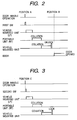
- Fig. 2 illustrates an aspect of the operation of the passive keyless entry system according to the present embodiment for unlocking a door-locking mechanism.
- Fig. 3 illustrates an aspect of the operation of the passive keyless entry system according to the present embodiment for locking the door-locking mechanism.
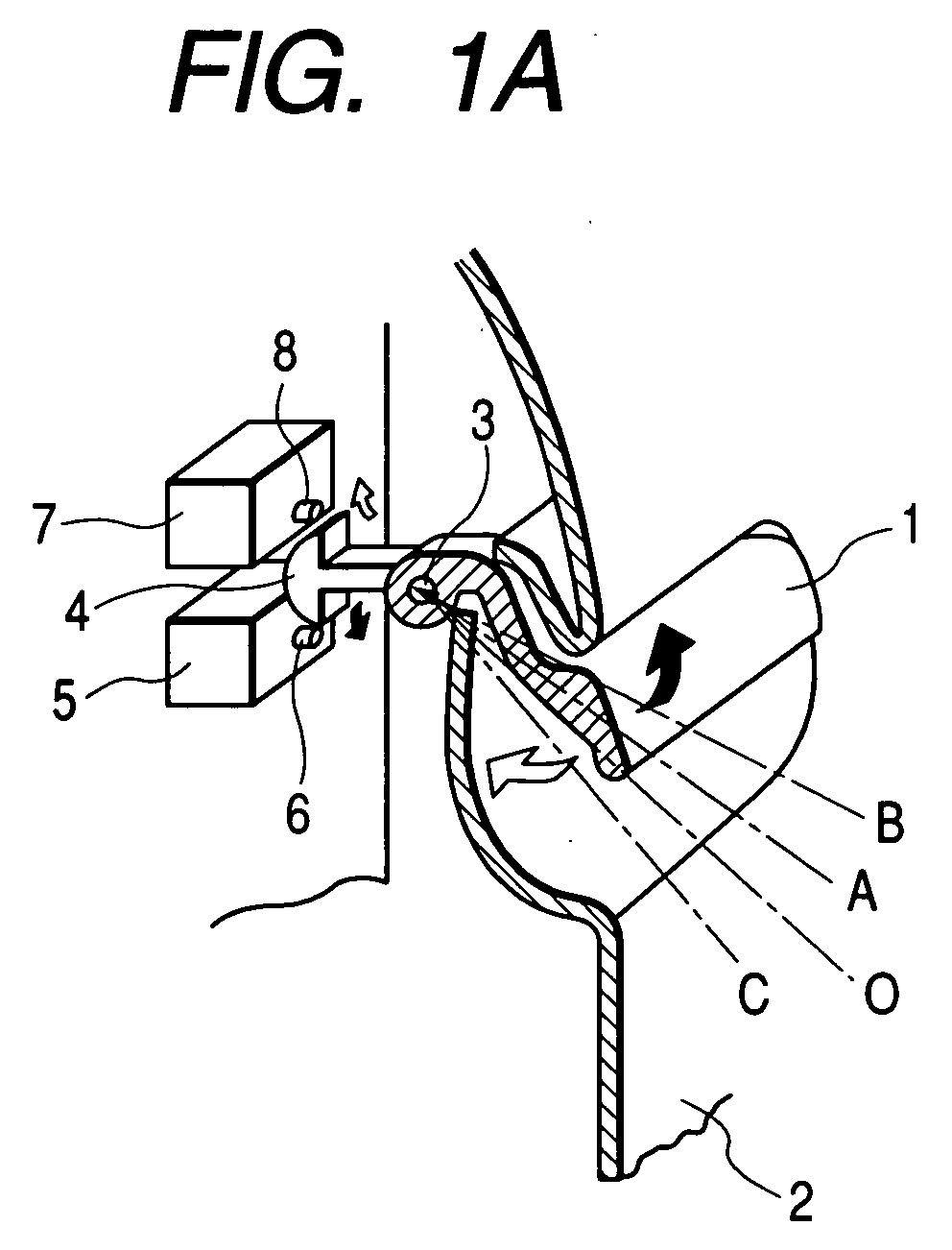
- reference numerals 1, 2, 3, 4, 5, 6, 7, and 8 denote an outside handle, a door outer plate, a rotary shaft, a driving unit, a first switch, a first actuator, a second switch, and a second actuator, respectively.
- Fig. 1 illustrates the periphery of the outside handle of a vehicle door.
- Fig. 1A is a schematic view illustrating relations between the operation positions of the outside handle and the first and second switches.
- Fig. 1B is a sectional view illustrating the operation position of the outside handle.
- a recess into which a hand is put is provided in the external surface of the door outer plate 2 so that the outside handle 1 can be pulled or pushed using the rotary shaft 3 provided in the upper portion of the recess as a pivotal point.
- a circuit substrate having an electric circuit mounted thereon is received inside the vehicle door.
- Two switches, that is, the first switch 5 and the second switch 7 are mounted on the circuit substrate that faces a portion in which the outside handle 1 is mounted.
- the first actuator 6 and the second actuator 8 protrude from the cases of the first and second switches 5 and 7 on the side of the outside handle.
- the driving unit 4 extending to the central positions of the two switches 5 and 7 is integrally attached to the outside handle 1 in the directions of the first switch 5 and the second switch 7.
- the side that faces the two switches 5 and 7 is formed substantially in an arc shape.
- the driving unit 4 is separated from the two switches 5 and 7 when the outside handle 1 is not operated.
- the arc-shaped surface is moved to press the first actuator 6 of the first switch 5 to turn on the first switch 5 or to press the second actuator 8 of the second switch 7 to turn on the second switch 7.
- the position O of the outside handle 1 is the normal position of the outside handle 1 when the vehicle door is closed, and when a operator pivots the outside handle 1 using the rotary shaft 3 as a pivotal center while getting on a vehicle, the vehicle door is forcibly opened based on the operation force of the vehicle door in the position B.
- a door-locking mechanism is unlocked by bi-directional communication between a vehicle-mounted unit and a portable unit with the lapse of the operations of the outside handle 1 from the position O to the position B when the operator gets on a vehicle. Further, the door-locking mechanism is locked by the bi-directional communication between the vehicle-mounted unit and the portable unit by further pushing the outside handle 1 inwardly from the position O when the operator gets off the vehicle.
- the outside handle 1 holds its stable position in the normal position O with biasing means (not shown).
- the second actuator 8 of the first switch 5 is operated in the position A where the outside handle 1 is positioned in an initial stage of the pulling operation, by the driving unit 4 integral with the outside handle 1 to thereby turn on the first switch 5.
- the second actuator 8 of the second switch 7 is operated by the driving unit 4 integral with the outside handle 1 to thereby turn on the second switch 7.
- Fig. 2 according to the passive keyless entry (P-RKE) system of the present embodiment, when the operator pulls the outside handle 1 in the direction from the normal position O to the.position B while getting on the vehicle (refer to Fig. 1), the first actuator 6 of the first switch 5 is operated in the position A where the pulling operation is initially performed to thereby generate a trigger signal that allows the vehicle-mounted unit to transmit a low frequency (LF) request signal including an vehicle-mounted unit ID.
- the portable unit receives the request signal and collates the vehicle-mounted unit ID included in the received request signal with an authentic vehicle-mounted unit ID.
- P-RKE passive keyless entry
- the door-locking mechanism is unlocked (the locking of the door-locking mechanism is released.). Next, it is possible to forcibly open the door outer plate 2 of the unlocked door by the operator pivoting the outside handle 1 to the position B.
- Fig. 3 when the operator pushes the outside handle 1 to the direction of the position C that is opposite to the direction of the position B, in which the vehicle door is opened, using the PKE system according to the present embodiment, while getting off the vehicle (refer to Fig. 1), the second actuator 8 of the second switch 7 is operated in the position C where the pushing operation is performed to thereby generate the trigger signal that allows the vehicle-mounted unit to transmit the LF request signal including the vehicle-mounted unit ID.
- the portable unit receives the request signal, collates the vehicle-mounted unit ID included in the received request signal with an authentic vehicle-mounted unit ID, and transmits a radio frequency (RF) response signal including a portable unit ID.
- RF radio frequency
- the vehicle-mounted unit receives the response signal, collates the portable unit ID included in the received response signal with an authentic portable unit ID, and locks the door-locking mechanism after determining that the trigger signal has been received from the second switch 7 when the former coincides with the latter. Moreover, the door-locking mechanism is locked after forcibly closing the door outer plate 2. When the outside handle 1 is pushed, the door outer plate 2 is forcibly closed to thereby lock the door-locking mechanism.
- the door-locking mechanism is unlocked by the operation of pulling the outside handle 1 and the door-locking mechanism is locked by the operation of pushing the outside handle 1. Therefore, it is not necessary to provide an exclusive switch in the vehicle door after locking or unlocking the door-locking mechanism, and it is possible to unlock the door-locking mechanism by the operation of opening the outside handle and to lock the door-locking mechanism by the operation of closing the outside handle. As a result, it is possible to unlock or lock the door-locking mechanism in accordance with the intention of the operator who operates the outside handle.
- the trigger signal for locking and unlocking the door-locking mechanism is generated by the operation of the outside handle for opening and closing the vehicle door without providing the exclusive switch, it is possible to realize the PKE system with a simple structure.
Landscapes
- Engineering & Computer Science (AREA)
- Computer Networks & Wireless Communication (AREA)
- Physics & Mathematics (AREA)
- General Physics & Mathematics (AREA)
- Lock And Its Accessories (AREA)
Abstract
Description
Claims (3)
- A passive keyless entry system for locking or unlocking a vehicle door, the passive keyless entry system comprising trigger switches for transmitting a request signal to a portable unit,
wherein the trigger switches are attached to an outside handle for opening or closing the vehicle door,
wherein the trigger switches comprise a first switch turned on or off by the operation of pulling the outside handle from a normal position and a second switch turned on or off by the operation of pushing the outside handle from the normal position,
wherein a request signal is transmitted from the vehicle to the portable unit by the first switch operation and, when the request signal includes an authentic portable unit ID, the portable unit transfers a response signal to thereby unlock the vehicle door, and
wherein a request signal is transmitted from the vehicle to the portable unit by the second switch operation and, when the request signal includes an authentic portable unit ID, the portable unit transfers a response signal to thereby lock the vehicle door. - The passive keyless entry system according to Claim 1,
wherein a driving unit is provided in the outside handle, and
wherein the first switch and the second switch are disposed on both sides of the driving unit. - The passive keyless entry system according to Claim 1 or 2,
wherein the vehicle door is unlocked and then opened by the operation of pulling the outside handle from a normal position, and
wherein the vehicle door is closed and then locked by the operation of pushing the outside handle from a normal position.
Applications Claiming Priority (2)
| Application Number | Priority Date | Filing Date | Title |
|---|---|---|---|
| JP2003068524A JP2004278050A (en) | 2003-03-13 | 2003-03-13 | Passive keyless entry device and method |
| JP2003068524 | 2003-03-13 |
Publications (2)
| Publication Number | Publication Date |
|---|---|
| EP1457932A2 true EP1457932A2 (en) | 2004-09-15 |
| EP1457932A3 EP1457932A3 (en) | 2005-04-20 |
Family
ID=32767964
Family Applications (1)
| Application Number | Title | Priority Date | Filing Date |
|---|---|---|---|
| EP20040004855 Withdrawn EP1457932A3 (en) | 2003-03-13 | 2004-03-02 | Passive keyless entry system for vehicle |
Country Status (3)
| Country | Link |
|---|---|
| US (1) | US20040183655A1 (en) |
| EP (1) | EP1457932A3 (en) |
| JP (1) | JP2004278050A (en) |
Cited By (3)
| Publication number | Priority date | Publication date | Assignee | Title |
|---|---|---|---|---|
| WO2007074354A1 (en) * | 2005-12-29 | 2007-07-05 | Renault Trucks | Method for passive keyless entry of a motor vehicle especially of an industrial vehicle |
| DE102006058854A1 (en) * | 2006-12-13 | 2008-06-19 | Volkswagen Ag | Method for actuation of devices which are opened in motor vehicle, involves operating switch of motor vehicle which sends signal to controller of motor vehicle |
| WO2018036868A1 (en) * | 2016-08-23 | 2018-03-01 | Huf Hülsbeck & Fürst Gmbh & Co. Kg | Sensing system for detecting actuation of a handle device of a vehicle |
Families Citing this family (12)
| Publication number | Priority date | Publication date | Assignee | Title |
|---|---|---|---|---|
| US20060005590A1 (en) * | 2004-07-12 | 2006-01-12 | Lear Corporation | Mechanical door handle switch assembly with a dampening mechanism |
| US20060010943A1 (en) * | 2004-07-13 | 2006-01-19 | Lear Corporation | Mechanical handle switch assembly |
| JP4595540B2 (en) * | 2004-12-28 | 2010-12-08 | コクヨ株式会社 | Take-away prevention system |
| JP2007332739A (en) * | 2006-06-19 | 2007-12-27 | Denso Corp | Vehicle control system |
| US8427289B2 (en) | 2010-06-16 | 2013-04-23 | Lear Corporation | Low latency inside/outside determination for portable transmitter |
| US8712648B2 (en) | 2011-03-08 | 2014-04-29 | Gm Global Technology Operations | Passive charge cord release system for an electric vehicle |
| US8690591B2 (en) | 2011-06-09 | 2014-04-08 | GM Global Technology Operations LLC | Electric vehicle with secondary charge cord release mechanism |
| JP2016056526A (en) * | 2014-09-05 | 2016-04-21 | 株式会社デンソー | In-vehicle device |
| DE102016218206A1 (en) * | 2016-09-22 | 2018-03-22 | Volkswagen Aktiengesellschaft | Unlocking unit with a variable trip switching point |
| DE102021214163A1 (en) | 2021-12-10 | 2023-06-15 | Witte Automotive Gmbh | Vehicle door with a handle assembly and vehicle |
| CN115434583B (en) * | 2022-05-05 | 2024-08-30 | 北京罗克维尔斯科技有限公司 | Control method and device of hidden handle, vehicle and electronic equipment |
| DE102024138742A1 (en) * | 2024-02-05 | 2025-08-07 | Illinois Tool Works Inc. | Actuating device for a door handle assembly of a vehicle |
Family Cites Families (8)
| Publication number | Priority date | Publication date | Assignee | Title |
|---|---|---|---|---|
| DE3536377A1 (en) * | 1985-10-11 | 1987-04-16 | Bayerische Motoren Werke Ag | SAFETY DEVICE FOR MOTOR VEHICLES |
| JP2546842B2 (en) * | 1987-06-16 | 1996-10-23 | 日産自動車株式会社 | Vehicle locking / unlocking control device |
| US4898010A (en) * | 1987-10-28 | 1990-02-06 | Nissan Motor Company, Limited | Keyless entry system for automotive vehicles |
| TW404365U (en) * | 1998-11-30 | 2000-09-01 | Tung Thih Entpr Co Ltd | Automobile remote controller without key |
| DE19930861A1 (en) * | 1999-07-05 | 2001-01-25 | Valeo Gmbh & Co Schliessyst Kg | Vehicle door handle has pivot lever on actuating lever extending into interior of vehicle door to actuate switch and functional element when actuating element pivoted into switching position |
| JP4552169B2 (en) * | 1999-11-09 | 2010-09-29 | マツダ株式会社 | Control device for opening / closing body of vehicle |
| FR2802564B1 (en) * | 1999-12-21 | 2002-02-15 | Valeo Securite Habitacle | SAFETY SYSTEM OF A MOTOR VEHICLE OPENING ELEMENT WITH SWITCHES WITHOUT MECHANICAL OPERATION |
| JP2004003152A (en) * | 2002-05-31 | 2004-01-08 | Fuji Heavy Ind Ltd | Keyless entry device for vehicles |
-
2003
- 2003-03-13 JP JP2003068524A patent/JP2004278050A/en not_active Withdrawn
-
2004
- 2004-03-02 EP EP20040004855 patent/EP1457932A3/en not_active Withdrawn
- 2004-03-09 US US10/796,821 patent/US20040183655A1/en not_active Abandoned
Cited By (5)
| Publication number | Priority date | Publication date | Assignee | Title |
|---|---|---|---|---|
| WO2007074354A1 (en) * | 2005-12-29 | 2007-07-05 | Renault Trucks | Method for passive keyless entry of a motor vehicle especially of an industrial vehicle |
| US8179230B2 (en) | 2005-12-29 | 2012-05-15 | Renault Trucks | Method for passive keyless entry of a motor vehicle especially of an industrial vehicle |
| DE102006058854A1 (en) * | 2006-12-13 | 2008-06-19 | Volkswagen Ag | Method for actuation of devices which are opened in motor vehicle, involves operating switch of motor vehicle which sends signal to controller of motor vehicle |
| DE102006058854B4 (en) * | 2006-12-13 | 2017-08-03 | Volkswagen Ag | Method for actuating devices to be opened of a motor vehicle and corresponding device and corresponding motor vehicle |
| WO2018036868A1 (en) * | 2016-08-23 | 2018-03-01 | Huf Hülsbeck & Fürst Gmbh & Co. Kg | Sensing system for detecting actuation of a handle device of a vehicle |
Also Published As
| Publication number | Publication date |
|---|---|
| EP1457932A3 (en) | 2005-04-20 |
| JP2004278050A (en) | 2004-10-07 |
| US20040183655A1 (en) | 2004-09-23 |
Similar Documents
| Publication | Publication Date | Title |
|---|---|---|
| US6707375B2 (en) | Keyless entry apparatus capable of selectively controlling only member to be controlled closest to user | |
| US20040183655A1 (en) | Passive keyless entry system for vehicle | |
| EP1367200B1 (en) | Key-less entry system for vehicle | |
| US7394350B2 (en) | Power-saving on-vehicle controller | |
| KR100766189B1 (en) | Vehicle door control system and method | |
| EP2154035B1 (en) | Smart entry system and method | |
| US6657537B1 (en) | Device for initiating an authorization request for a vehicle | |
| US8193906B2 (en) | Mechanical key code verification system | |
| US6876292B2 (en) | Electronic key system for vehicle | |
| WO2002025040A1 (en) | Proximity activated entry system | |
| JP3799961B2 (en) | Electronic key device for vehicle | |
| JP2002540320A (en) | Keyless type access check device for automobile | |
| JP3582384B2 (en) | In-vehicle equipment remote control device | |
| WO2006115159A1 (en) | Automobile | |
| JP4569305B2 (en) | Smart entry system for vehicles | |
| JP3430720B2 (en) | Keyless entry device | |
| KR100412215B1 (en) | Door unlocking method | |
| JP2004019380A (en) | In-vehicle equipment remote control system | |
| JP2009256900A (en) | Locking-unlocking system | |
| JP3879397B2 (en) | Keyless entry system | |
| JP3968900B2 (en) | Keyless entry device | |
| JP4122805B2 (en) | Door lock control device | |
| US20060279403A1 (en) | Anti-theft securing method for hands-free vehicle access systems | |
| JP2008240337A (en) | Door lock control device | |
| JP2005299264A (en) | Key device incorporating radiotag |
Legal Events
| Date | Code | Title | Description |
|---|---|---|---|
| PUAI | Public reference made under article 153(3) epc to a published international application that has entered the european phase |
Free format text: ORIGINAL CODE: 0009012 |
|
| AK | Designated contracting states |
Kind code of ref document: A2 Designated state(s): AT BE BG CH CY CZ DE DK EE ES FI FR GB GR HU IE IT LI LU MC NL PL PT RO SE SI SK TR |
|
| AX | Request for extension of the european patent |
Extension state: AL LT LV MK |
|
| PUAL | Search report despatched |
Free format text: ORIGINAL CODE: 0009013 |
|
| AK | Designated contracting states |
Kind code of ref document: A3 Designated state(s): AT BE BG CH CY CZ DE DK EE ES FI FR GB GR HU IE IT LI LU MC NL PL PT RO SE SI SK TR |
|
| AX | Request for extension of the european patent |
Extension state: AL LT LV MK |
|
| AKX | Designation fees paid | ||
| STAA | Information on the status of an ep patent application or granted ep patent |
Free format text: STATUS: THE APPLICATION IS DEEMED TO BE WITHDRAWN |
|
| 18D | Application deemed to be withdrawn |
Effective date: 20051021 |
|
| REG | Reference to a national code |
Ref country code: DE Ref legal event code: 8566 |