EP1457729A1 - Spacer for an elongate substrate - Google Patents
Spacer for an elongate substrate Download PDFInfo
- Publication number
- EP1457729A1 EP1457729A1 EP04290418A EP04290418A EP1457729A1 EP 1457729 A1 EP1457729 A1 EP 1457729A1 EP 04290418 A EP04290418 A EP 04290418A EP 04290418 A EP04290418 A EP 04290418A EP 1457729 A1 EP1457729 A1 EP 1457729A1
- Authority
- EP
- European Patent Office
- Prior art keywords
- rings
- pipe section
- spacer according
- ring
- spacer
- Prior art date
- Legal status (The legal status is an assumption and is not a legal conclusion. Google has not performed a legal analysis and makes no representation as to the accuracy of the status listed.)
- Granted
Links
Images

Classifications
-
- F—MECHANICAL ENGINEERING; LIGHTING; HEATING; WEAPONS; BLASTING
- F16—ENGINEERING ELEMENTS AND UNITS; GENERAL MEASURES FOR PRODUCING AND MAINTAINING EFFECTIVE FUNCTIONING OF MACHINES OR INSTALLATIONS; THERMAL INSULATION IN GENERAL
- F16L—PIPES; JOINTS OR FITTINGS FOR PIPES; SUPPORTS FOR PIPES, CABLES OR PROTECTIVE TUBING; MEANS FOR THERMAL INSULATION IN GENERAL
- F16L59/00—Thermal insulation in general
- F16L59/06—Arrangements using an air layer or vacuum
- F16L59/065—Arrangements using an air layer or vacuum using vacuum
-
- F—MECHANICAL ENGINEERING; LIGHTING; HEATING; WEAPONS; BLASTING
- F16—ENGINEERING ELEMENTS AND UNITS; GENERAL MEASURES FOR PRODUCING AND MAINTAINING EFFECTIVE FUNCTIONING OF MACHINES OR INSTALLATIONS; THERMAL INSULATION IN GENERAL
- F16L—PIPES; JOINTS OR FITTINGS FOR PIPES; SUPPORTS FOR PIPES, CABLES OR PROTECTIVE TUBING; MEANS FOR THERMAL INSULATION IN GENERAL
- F16L59/00—Thermal insulation in general
- F16L59/12—Arrangements for supporting insulation from the wall or body insulated, e.g. by means of spacers between pipe and heat-insulating material; Arrangements specially adapted for supporting insulated bodies
-
- F—MECHANICAL ENGINEERING; LIGHTING; HEATING; WEAPONS; BLASTING
- F16—ENGINEERING ELEMENTS AND UNITS; GENERAL MEASURES FOR PRODUCING AND MAINTAINING EFFECTIVE FUNCTIONING OF MACHINES OR INSTALLATIONS; THERMAL INSULATION IN GENERAL
- F16L—PIPES; JOINTS OR FITTINGS FOR PIPES; SUPPORTS FOR PIPES, CABLES OR PROTECTIVE TUBING; MEANS FOR THERMAL INSULATION IN GENERAL
- F16L59/00—Thermal insulation in general
- F16L59/14—Arrangements for the insulation of pipes or pipe systems
- F16L59/141—Arrangements for the insulation of pipes or pipe systems in which the temperature of the medium is below that of the ambient temperature
Definitions
- the invention relates to a spacer for an elongated substrate inside an elongated pipe according to claim 1 and a coaxial pipe system with a such a spacer according to claim 10.
- the invention is based on the following consideration:
- the heat loss flows Q Gas are reduced by evacuating the insulation room.
- the solid thermal bridges z. B. by spacers, which are responsible for Q FK , are structurally reduced by minimizing the solid-state contact currents.
- the radiation losses Q Rad are reduced by mirroring the inner walls or by installing highly reflective foils.
- Q FK plays a crucial role in flexible, vacuum-insulated cryogenic conduits. So that the cold inner pipe has no direct contact with the outer pipe at room temperature at any point in the pipe run, spacers have been used in various designs. These must be able to transmit as large a force component as possible, but have the same low thermal conductivity property. The known spacers have the disadvantage of not implementing the two necessary objectives to the same extent. If a low heat conduction was achieved, the mechanical resilience was low, with high mechanical resilience a very high heat conduction had to be accepted.
- From DE-C2-2 136 176 is one consisting of two concentric tubes Pipe system z.
- B an electric cable operated at low temperatures or a Pipeline for the transport of liquid or gaseous heated or cooled media known
- the inner tube in the surrounding outer tube by material-poor Spacer is held in place.
- the spacers sit on the at intervals Inner tube and are supported on the inner surface of the outer tube.
- the Spacers consist of several slotted rings, the slot width of which Corresponds to the diameter of the inner tube.
- the rings are interconnected so that they are one common axis of rotation are pivotable.
- the outer tube is supported on the outer circumference of what is formed from the rings Spacer. This construction is very low in materials, but requires a lot Space in the isolation area. Since the permanent attachment of the thread elements continues the rings are difficult and the connection can come loose under a tensile load, this spacer is less suitable for bendable pipe systems than for such bendable pipe systems can withstand tensile or compressive loads of more than 10000 N occur.
- a spacer for a coaxial pipe system is known from US Pat. No. 2,914,090. which sit at a longitudinal axial distance from each other on the inner tube and these in Keep a distance from the outer tube.
- Each spacer consists of one that Inner tube enveloping inner metallic tube piece and one on the inner wall of the outer tube, which is also made of metal and which is made of metal. Between the inner and the outer pipe section are evenly over the circumference distributed three spoke-shaped struts provided, both on the inner and on the outer pipe section are welded.
- the inner tube piece is made of two coaxial Tubes formed, between which there is a thermal insulation z. B. made of asbestos located.
- This spacer has a high mechanical strength, it lacks but the required insulation properties.
- the object of the invention is therefore to provide a spacer, the material is low and therefore has good thermal insulation properties and can withstand high mechanical loads.
- FIGS. 1 and 2 Exemplary embodiments explained.
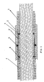
- FIG 1 is one of two concentrically arranged conduits existing pipe system shown, which, for. B. for the transport of cryogenic media should be used.
- the pipe system consists of a corrugated metallic inner pipe 1, preferably made of stainless steel and a corrugated metallic outer tube 2, which is preferably also made of stainless steel.
- a corrugated metallic inner pipe 1 preferably made of stainless steel
- a corrugated metallic outer tube 2 which is preferably also made of stainless steel.
- the rings 3 and 4 of the pipe section 5 and the Ring 6 are made of fiber reinforced plastic, e.g. B. glass fiber reinforced epoxy manufactured.
- the spacer can be composed of parts 3, 4, 5 and 6 and as The whole be pushed onto the inner tube 1.
- the spacer manufactured as a whole can be separated into two parts be so that it can be attached laterally to the inner tube.
- the super insulation 7 is also provided in the area of the spacer. You can at an embodiment of the spacer from two parts, which laterally on the inner tube 1st be attached, attached to the inner wall of the pipe section 5.
- the super insulation 7 is initially via the entire length of the inner tube 1 wound. Then the Spacers are attached to the super insulation, which is in the area of the rings 3 and 4 is compressed.
- the inner tube 1 is first manufactured and placed on a storage drum wound.
- the super insulation 7 can be used in the manufacture of the inner tube 1 in the same Operation.
- the insulated inner tube 1 is removed from the storage drum removed and the spacers are attached to the super insulation.
- a metal tape is pulled from a supply spool and in continuous Working around the inner tube 1 formed into a slotted tube, longitudinally welded and corrugated. On the outer tube 2 thus formed can still Plastic jacket are extruded.
- the gap between the inner and outer pipes is evacuated at the installation location.
Landscapes
- Engineering & Computer Science (AREA)
- General Engineering & Computer Science (AREA)
- Mechanical Engineering (AREA)
- Thermal Insulation (AREA)
- Rigid Pipes And Flexible Pipes (AREA)
Abstract
Description
Die Erfindung betrifft einen Abstandshalter für ein langgestrecktes Substrat im Innern eines langgestreckten Rohres nach Anspruch 1 sowie ein koaxiales Rohrsystem mit einem solchen Abstandshalter nach Anspruch 10.The invention relates to a spacer for an elongated substrate inside an elongated pipe according to claim 1 and a coaxial pipe system with a such a spacer according to claim 10.
Die Erfindung geht von folgender Überlegung aus:The invention is based on the following consideration:
Eine optimale thermische Isolierung in der Kältetechnik wird durch eine Vielschicht-Folienisolierung im Hochvakuum erreicht (Superisolierung). Dabei wird der Gesamtwärmestrom durch Minimieren der Komponenten QGas, QFK und QRad auf den technisch bisher geringstmöglichen Wert gebracht.Optimal thermal insulation in refrigeration technology is achieved by multi-layer foil insulation in a high vacuum (super insulation). By minimizing the components Q Gas , Q FK and Q Rad , the total heat flow is brought to the technically lowest possible value.
Die Verlustwärmeströme QGas werden durch Evakuieren des Isolationsraums reduziert.The heat loss flows Q Gas are reduced by evacuating the insulation room.
Die Feststoff-Wärmebrücken z. B. durch Abstandshalter, die verantwortlich für QFK sind, werden konstruktiv durch Minimieren der Festkörperkontaktströme reduziert.The solid thermal bridges z. B. by spacers, which are responsible for Q FK , are structurally reduced by minimizing the solid-state contact currents.
Die Strahlungsverluste QRad werden durch Verspiegelung der Innenwände oder durch Einbau hochreflektierender Folien reduziert. The radiation losses Q Rad are reduced by mirroring the inner walls or by installing highly reflective foils.
QFK spielt gerade bei flexiblen, vakuumisolierten Kryoleitungsrohren eine entscheidende Rolle. Damit das kalte Innenrohr an keiner Stelle im Rohrverlauf direkten Kontakt zu dem auf Raumtemperatur befindlichen Außenrohr hat, wurden bisher Abstandhalter in verschiedenen Konstruktionen eingesetzt. Diese müssen eine möglichst große Kraftkomponente übertragen können, aber in gleichem Maße die Eigenschaft einer geringen Wärmeleitfähigkeit haben. Die bekannten Abstandshalter haben den Nachteil, die beiden notwendigen Zielsetzungen nicht in gleich gutem Maße umzusetzen. Falls eine geringe Wärmeleitung erreicht wurde, war die mechanische Belastbarkeit gering, bei hoher mechanischer Belastbarkeit mußte eine sehr hohe Wärmeleitung in Kauf genommen werden.Q FK plays a crucial role in flexible, vacuum-insulated cryogenic conduits. So that the cold inner pipe has no direct contact with the outer pipe at room temperature at any point in the pipe run, spacers have been used in various designs. These must be able to transmit as large a force component as possible, but have the same low thermal conductivity property. The known spacers have the disadvantage of not implementing the two necessary objectives to the same extent. If a low heat conduction was achieved, the mechanical resilience was low, with high mechanical resilience a very high heat conduction had to be accepted.
Aus der DE-C2-2 136 176 ist ein aus zwei konzentrischen Rohren bestehendes Rohrsystem z. B. ein bei tiefen Temperaturen betriebenes elektrisches Kabel oder eine Rohrleitung zum Transport flüssiger oder gasförmiger erwärmter oder gekühlter Medien bekannt, dessen inneres Rohr in dem umgebenden äußeren Rohr durch materialarme Abstandshalter in Lage gehalten ist. Die Abstandshalter sitzen in Abständen auf dem Innenrohr auf und stützen sich an der inneren Oberfläche des Außenrohres ab. Der Abstandshalter besteht aus mehreren geschlitzten Ringen, deren Schlitzbreite dem Durchmesser des Innenrohres entspricht. An jedem Ring ist im Schlitzbereich ein Fadenelement befestigt. Die Ringe sind so miteinander verbunden, daß sie um eine gemeinsame Drehachse schwenkbar sind. Beim Aufstecken des Abstandshalters auf das Innenrohr legen sich die Fadenelemente teilweise um das Innenrohr herum. Das Außenrohr stützt sich auf dem äußeren Umfang des aus den Ringen bebildeten Abstandshalters ab. Diese Konstruktion ist sehr materialarm, benötigt jedoch relativ viel Platz im Isolierbereich. Da weiterhin die dauerhafte Befestigung der Fadenelemente an den Ringen schwierig ist und die Anbindung sich unter einer Zugbelastung lösen kann, ist dieser Abstandshalter für biegbare Rohrsysteme weniger geeignet, denn bei solchen biegbaren Rohrsysteme können beim Biegen Zug- bzw. Druckbelastungen von mehr als 10000 N auftreten. From DE-C2-2 136 176 is one consisting of two concentric tubes Pipe system z. B. an electric cable operated at low temperatures or a Pipeline for the transport of liquid or gaseous heated or cooled media known, the inner tube in the surrounding outer tube by material-poor Spacer is held in place. The spacers sit on the at intervals Inner tube and are supported on the inner surface of the outer tube. The Spacers consist of several slotted rings, the slot width of which Corresponds to the diameter of the inner tube. On each ring there is a slot area Thread element attached. The rings are interconnected so that they are one common axis of rotation are pivotable. When placing the spacer on the Inner tube partially thread the thread elements around the inner tube. The The outer tube is supported on the outer circumference of what is formed from the rings Spacer. This construction is very low in materials, but requires a lot Space in the isolation area. Since the permanent attachment of the thread elements continues the rings are difficult and the connection can come loose under a tensile load, this spacer is less suitable for bendable pipe systems than for such bendable pipe systems can withstand tensile or compressive loads of more than 10000 N occur.
Aus der US 2 914 090 ist ein Abstandshalter für ein koaxiales Rohrsystem bekannt, welche in längsaxialem Abstand zueinander auf dem Innenrohr sitzen und diese im Abstand zum äußeren Rohr halten. Jeder Abstandshalter besteht aus einem das Innenrohr umhüllenden inneren metallischen Rohrstück sowie einem an der Innenwand des Außenrohres anliegenden ebenfalls aus Metall bestehenden äußeren Rohrstück. Zwischen dem inneren und dem äußeren Rohrstück sind gleichmäßig über dem Umfang verteilt drei speichenförmige Streben vorgesehen, die sowohl am inneren wie auch am äußeren Rohrstück angeschweißt sind. Das innere Rohrstück ist aus zwei koaxialen Rohren ausgebildet, zwischen denen sich eine thermische Isolierung z. B. aus Asbest befindet.A spacer for a coaxial pipe system is known from US Pat. No. 2,914,090. which sit at a longitudinal axial distance from each other on the inner tube and these in Keep a distance from the outer tube. Each spacer consists of one that Inner tube enveloping inner metallic tube piece and one on the inner wall of the outer tube, which is also made of metal and which is made of metal. Between the inner and the outer pipe section are evenly over the circumference distributed three spoke-shaped struts provided, both on the inner and on the outer pipe section are welded. The inner tube piece is made of two coaxial Tubes formed, between which there is a thermal insulation z. B. made of asbestos located.
Dieser Abstandshalter weist zwar eine hohe mechanische Festigkeit auf, es mangelt ihm aber an den erforderlichen Isoliereigenschaften.This spacer has a high mechanical strength, it lacks but the required insulation properties.
Der Erfindung liegt von daher die Aufgabe zugrunde, einen Abstandshalter abzugeben, der materialarm ausgebildet ist und von daher gute Wärmeisoliereigenschaften aufweist sowie hohe mechanische Belastungen auszuhalten vermag.The object of the invention is therefore to provide a spacer, the material is low and therefore has good thermal insulation properties and can withstand high mechanical loads.
Diese Aufgabe wird durch die im Kennzeichen des Anspruchs 1 angegebenen Merkmale gelöst.This object is achieved by the features specified in the characterizing part of claim 1 solved.
Weitere vorteilhafte Ausgestaltungen des Abstandshalters sind in den Unteransprüchen erfaßt.Further advantageous embodiments of the spacer are in the subclaims detected.
Die Erfindung ist anhand der in den Figuren 1 und 2 schematisch dargestellten Ausführungsbeispiele erläutert.The invention is illustrated schematically in FIGS. 1 and 2 Exemplary embodiments explained.
In der Figur 1 ist ein aus zwei konzentrisch zueinander angeordneten Leitungsrohren bestehendes Rohrsystem dargestellt, welches z. B. zum Transport cryogener Medien verwendet werden soll. In the figure 1 is one of two concentrically arranged conduits existing pipe system shown, which, for. B. for the transport of cryogenic media should be used.
Das Rohrsystem besteht aus einem gewellten metallischen Innenrohr 1, vorzugsweise aus
nichtrostendem Stahl sowie einem ebenfalls gewellten metallischen Außenrohr 2,
welches vorzugsweise ebenfalls aus nichtrostendem Stahl besteht. Durch die Wellung des
Innenrohres 1 sowie des Außenrohres 2 ist das Rohrsystem flexibel und kann auf
Transporttrommeln aufgewickelt und damit zum Anwendungsort transportiert werden.
Wenn die Rohre 1 und 2 durch Formen eines nahezu endlosen Metallbandes zu einem
Rohr mit Längsschlitz, verschweißen des Längsschlitzes und anschließendes Wellen des
Rohres hergestellt werden, können Rohre von nahezu endloser Länge hergestellt
werden.The pipe system consists of a corrugated metallic inner pipe 1, preferably made of
stainless steel and a corrugated metallic
Zwischen dem Innenrohr 1 und dem Außenrohr 2 befinden sich in bestimmten
längsaxialen Abständen Abstandshalter, welche aus zwei auf dem Innenrohr 1 sitzenden
Ringen 3 und 4, einem Rohrstück 5 sowie einem zwischen dem Rohrstück 5 und dem
Außenrohr 2 befindlichen Ring 6 besteht. Die Ringe 3 und 4 des Rohrstücks 5 sowie der
Ring 6 sind aus faserverstärktem Kunststoff, z. B. glasfaserverstärkten Epoxidharz
hergestellt.Are located between the inner tube 1 and the
Der Abstandshalter kann aus den Teilen 3, 4, 5 und 6 zusammengesetzt sein und als
Ganzes auf das Innenrohr 1 aufgeschoben sein.The spacer can be composed of
Alternativ hierzu kann der als Ganzes hergestellte Abstandshalter in zwei Teile getrennt sein, so daß er seitlich auf das Innenrohr aufgesteckt werden kann.Alternatively, the spacer manufactured as a whole can be separated into two parts be so that it can be attached laterally to the inner tube.
Zwischen Innenrohr 1 und Außenrohr 2 befindet sich eine sogenannte Superisolierung
7, die aus einer Vielzahl von Lagen aus metallisierten Kunststofffolien besteht.There is a so-called super insulation between the inner tube 1 and
Die Superisolierung 7 ist auch im Bereich des Abstandshalters vorgesehen. Sie kann bei
einer Ausgestaltung des Abstandshalters aus zwei Teilen, die seitlich auf das Innenrohr 1
aufgesteckt werden, an der Innenwandung des Rohrstücks 5 befestigt sein. The
Bei dem Ausführungsbeispiel nach Figur 2 ist die Superisolierung 7 zunächst über die
gesamte Länge des Innenrohres 1 aufgewickelt. Anschließend werden die
Abstandshalter auf die Superisolierung aufgesteckt, die dabei im Bereich der Ringe 3
und 4 komprimiert wird.In the exemplary embodiment according to FIG. 2, the
Diese Vorgehensweise bietet sich an, wenn große Längen des Rohrsystems gefertigt werden sollen.This procedure is useful when manufacturing large lengths of the pipe system should be.
Dabei wird zunächst das Innenrohr 1 gefertigt und auf eine Vorratstrommel
aufgewickelt. Die Superisolierung 7 kann bei der Fertigung des Innenrohres 1 im selben
Arbeitsgang aufgewickelt werden.The inner tube 1 is first manufactured and placed on a storage drum
wound. The
Im nächsten Arbeitsgang wird das isolierte Innenrohr 1 von der Vorratstrommel abgezogen und die Abstandshalter werden auf die Superisolierung aufgesteckt.In the next step, the insulated inner tube 1 is removed from the storage drum removed and the spacers are attached to the super insulation.
Ein Metallband wird von einer Vorratsspule abgezogen und in kontinuierlicher
Arbeitsweise um das Innenrohr 1 herum zu einem Schlitzrohr geformt,
längsnahtgeschweißt und gewellt. Auf das so gebildete Außenrohr 2 kann noch ein
Kunststoffmantel aufextrudiert werden.A metal tape is pulled from a supply spool and in continuous
Working around the inner tube 1 formed into a slotted tube,
longitudinally welded and corrugated. On the
Am Verlegeort wird der Spalt zwischen dem Innen- und dem Außenrohr evakuiert.The gap between the inner and outer pipes is evacuated at the installation location.
Claims (10)
Applications Claiming Priority (2)
| Application Number | Priority Date | Filing Date | Title |
|---|---|---|---|
| DE10310960 | 2003-03-13 | ||
| DE10310960A DE10310960A1 (en) | 2003-03-13 | 2003-03-13 | Spacers for an elongated substrate |
Publications (2)
| Publication Number | Publication Date |
|---|---|
| EP1457729A1 true EP1457729A1 (en) | 2004-09-15 |
| EP1457729B1 EP1457729B1 (en) | 2007-01-10 |
Family
ID=32748225
Family Applications (1)
| Application Number | Title | Priority Date | Filing Date |
|---|---|---|---|
| EP04290418A Expired - Lifetime EP1457729B1 (en) | 2003-03-13 | 2004-02-16 | Spacer for an elongate substrate |
Country Status (4)
| Country | Link |
|---|---|
| US (1) | US6883548B2 (en) |
| EP (1) | EP1457729B1 (en) |
| DE (2) | DE10310960A1 (en) |
| DK (1) | DK1457729T3 (en) |
Cited By (2)
| Publication number | Priority date | Publication date | Assignee | Title |
|---|---|---|---|---|
| EP2146125A1 (en) * | 2008-07-17 | 2010-01-20 | Nexans | Flexible conduit pipe |
| US11976772B2 (en) | 2021-04-21 | 2024-05-07 | Integrity Products & Supplies Inc. | Pipe insulation spacer system |
Families Citing this family (5)
| Publication number | Priority date | Publication date | Assignee | Title |
|---|---|---|---|---|
| FR2939178B1 (en) * | 2008-12-03 | 2013-05-03 | Saipem Sa | UNDERWATER CONDUIT OF JUNCTION COMPRISING THERMAL INSULATION. |
| US20110192486A1 (en) * | 2010-02-05 | 2011-08-11 | Thomas Joseph Keyes | Water Spread Limiting System for Pre-Insulated Piping |
| RU2487228C1 (en) * | 2011-12-20 | 2013-07-10 | Общество С Ограниченной Ответственностью "Тмк-Премиум Сервис" | Section of heat-insulated string |
| US9377150B2 (en) * | 2014-02-20 | 2016-06-28 | Thermacor Process, Inc. | Method and apparatus for preserving the long term structural integrity of bonded foam pre-insulated piping systems |
| JP6580891B2 (en) * | 2015-07-15 | 2019-09-25 | 川崎重工業株式会社 | Liquid hydrogen loading arm |
Citations (6)
| Publication number | Priority date | Publication date | Assignee | Title |
|---|---|---|---|---|
| GB652331A (en) * | 1948-09-16 | 1951-04-18 | Gwyn Thomas | Improvements relating to the thermal insulation of pipes or tubes |
| US2914090A (en) | 1959-01-13 | 1959-11-24 | Alexander H Isenberg | Insulated supporting spacer rings for conduits |
| DE2136176C2 (en) | 1971-07-20 | 1983-12-22 | kabelmetal electro GmbH, 3000 Hannover | Pipe system consisting of two concentric pipes |
| US4496073A (en) * | 1983-02-24 | 1985-01-29 | The Johns Hopkins University | Cryogenic tank support system |
| EP0866259A2 (en) * | 1997-03-19 | 1998-09-23 | Alcatel | Spacer for an elongated substratum |
| WO2001050055A1 (en) * | 2000-01-07 | 2001-07-12 | Corus Uk Limited | Improved insulated pipework system |
Family Cites Families (17)
| Publication number | Priority date | Publication date | Assignee | Title |
|---|---|---|---|---|
| US534473A (en) * | 1895-02-19 | Conduit for steam or hot water | ||
| US903316A (en) * | 1908-07-22 | 1908-11-10 | Alois Reimann | Insulating covering for pipes. |
| US2664112A (en) * | 1949-02-07 | 1953-12-29 | Alexander H Isenberg | Spacer plate for pipes in insulated conduits |
| US2613166A (en) * | 1949-03-11 | 1952-10-07 | George E Gronemeyer | Thermal insulation |
| US3214994A (en) * | 1962-12-18 | 1965-11-02 | Ford Motor Co | Steering column noise barrier |
| DE1650060A1 (en) * | 1967-08-24 | 1970-08-27 | Kabel Metallwerke Ghh | Flexible pipe for the transport of liquids or gases |
| US3595275A (en) * | 1968-07-24 | 1971-07-27 | Vacuum Barrier Corp | Spacer means for cryogenic coaxial tubing |
| US3756268A (en) * | 1971-04-16 | 1973-09-04 | K Lefever | Method and apparatus for transporting petroleum products through a frozen medium |
| FR2159589A5 (en) * | 1971-11-04 | 1973-06-22 | Commissariat Energie Atomique | |
| US3952777A (en) * | 1972-12-20 | 1976-04-27 | Brown Boveri-Sulzer Turbomaschinen Aktiengesellschaft | Hollow body for heated gases |
| US4014369A (en) * | 1975-12-31 | 1977-03-29 | Exxon Research And Engineering Company | Triple pipe low temperature pipeline |
| US4219224A (en) * | 1978-04-06 | 1980-08-26 | Foundation Cryogenic Joint Venture | Cryogenic pipeline system |
| US6000420A (en) * | 1995-06-06 | 1999-12-14 | Horizon Resources Corporation | Insulating jacket for hot and cold piping systems and method of use |
| DE19818167A1 (en) * | 1998-04-23 | 1999-10-28 | Alcatel Sa | Flexible conduit pipe |
| DE19846587C1 (en) * | 1998-10-09 | 2000-03-16 | Karlsruhe Forschzent | Supporting system for superisolation in annular gap between flexible corrugated pipes has cylindrical rod frames between superisolation and inner and outer corrugated pipes |
| FR2803898B1 (en) * | 2000-01-14 | 2002-03-29 | Air Liquide | CRYOGENIC FLUID TRANSFER LINES AND USE FOR TRANSFERRING LIQUID HELIUM |
| US6736166B2 (en) * | 2002-04-26 | 2004-05-18 | Advance Products And Systems, Inc. | Casing spacer |
-
2003
- 2003-03-13 DE DE10310960A patent/DE10310960A1/en not_active Withdrawn
-
2004
- 2004-02-16 DK DK04290418T patent/DK1457729T3/en active
- 2004-02-16 DE DE502004002590T patent/DE502004002590D1/en not_active Expired - Lifetime
- 2004-02-16 EP EP04290418A patent/EP1457729B1/en not_active Expired - Lifetime
- 2004-03-12 US US10/798,330 patent/US6883548B2/en not_active Expired - Fee Related
Patent Citations (6)
| Publication number | Priority date | Publication date | Assignee | Title |
|---|---|---|---|---|
| GB652331A (en) * | 1948-09-16 | 1951-04-18 | Gwyn Thomas | Improvements relating to the thermal insulation of pipes or tubes |
| US2914090A (en) | 1959-01-13 | 1959-11-24 | Alexander H Isenberg | Insulated supporting spacer rings for conduits |
| DE2136176C2 (en) | 1971-07-20 | 1983-12-22 | kabelmetal electro GmbH, 3000 Hannover | Pipe system consisting of two concentric pipes |
| US4496073A (en) * | 1983-02-24 | 1985-01-29 | The Johns Hopkins University | Cryogenic tank support system |
| EP0866259A2 (en) * | 1997-03-19 | 1998-09-23 | Alcatel | Spacer for an elongated substratum |
| WO2001050055A1 (en) * | 2000-01-07 | 2001-07-12 | Corus Uk Limited | Improved insulated pipework system |
Cited By (2)
| Publication number | Priority date | Publication date | Assignee | Title |
|---|---|---|---|---|
| EP2146125A1 (en) * | 2008-07-17 | 2010-01-20 | Nexans | Flexible conduit pipe |
| US11976772B2 (en) | 2021-04-21 | 2024-05-07 | Integrity Products & Supplies Inc. | Pipe insulation spacer system |
Also Published As
| Publication number | Publication date |
|---|---|
| US20040194837A1 (en) | 2004-10-07 |
| DK1457729T3 (en) | 2007-05-07 |
| EP1457729B1 (en) | 2007-01-10 |
| DE10310960A1 (en) | 2004-09-23 |
| US6883548B2 (en) | 2005-04-26 |
| DE502004002590D1 (en) | 2007-02-22 |
Similar Documents
| Publication | Publication Date | Title |
|---|---|---|
| EP0326923A1 (en) | Conduit for the transport of cyrogenic fluids | |
| EP0952382B1 (en) | Flexible conduit | |
| DE1525658C3 (en) | Thermally insulated conduit | |
| DE1936641A1 (en) | Pipe arrangement and spacer band for this | |
| EP2146125B1 (en) | Flexible conduit pipe | |
| EP1795796B1 (en) | Conduit for the transport of cryogenic fluids | |
| EP1363062A1 (en) | Conduit for the transport of cryogenic fluids | |
| DE69934900T2 (en) | INSULATION CONSTRUCTION UNIT, SYSTEM AND METHOD FOR THE INSTALLATION AND MANUFACTURE THEREOF | |
| DE19846587C1 (en) | Supporting system for superisolation in annular gap between flexible corrugated pipes has cylindrical rod frames between superisolation and inner and outer corrugated pipes | |
| EP1344971B1 (en) | Conduit for the transport of cryogenic fluids | |
| DE3505045A1 (en) | INSULATED PLASTIC HOSE | |
| EP0866259B1 (en) | Spacer for an elongated substratum | |
| EP1457729B1 (en) | Spacer for an elongate substrate | |
| CH664205A5 (en) | HEAT-INSULATED PIPE. | |
| AT413589B (en) | FLEXIBLE CRYOGEN TUBE | |
| DE3018781C2 (en) | Thermally insulated pipe | |
| DE29615423U1 (en) | Heat insulated pipe | |
| DE1765527C3 (en) | Electric low-temperature cable designed as a coaxial pipe system | |
| DE3413747C2 (en) | ||
| EP0484491B1 (en) | Jacketed pipeline for the conveyance of gaseous or liquid media | |
| AT256956B (en) | Superconducting power transmission line | |
| EP1131580B1 (en) | Tubular construction | |
| DE3724360A1 (en) | Process for producing heat-insulated conduit pipes | |
| CH664204A5 (en) | Flexible tube for fluid transport is double-walled to monitor Leakage | |
| EP2732196B1 (en) | Method for producing a thermally insulated pipe, device for carrying out the method, and pipe produced according to the method |
Legal Events
| Date | Code | Title | Description |
|---|---|---|---|
| PUAI | Public reference made under article 153(3) epc to a published international application that has entered the european phase |
Free format text: ORIGINAL CODE: 0009012 |
|
| 17P | Request for examination filed |
Effective date: 20040617 |
|
| AK | Designated contracting states |
Kind code of ref document: A1 Designated state(s): AT BE BG CH CY CZ DE DK EE ES FI FR GB GR HU IE IT LI LU MC NL PT RO SE SI SK TR |
|
| AX | Request for extension of the european patent |
Extension state: AL LT LV MK |
|
| AKX | Designation fees paid |
Designated state(s): AT BE BG CH CY CZ DE DK EE ES FI FR GB GR HU IE IT LI LU MC NL PT RO SE SI SK TR |
|
| GRAP | Despatch of communication of intention to grant a patent |
Free format text: ORIGINAL CODE: EPIDOSNIGR1 |
|
| GRAS | Grant fee paid |
Free format text: ORIGINAL CODE: EPIDOSNIGR3 |
|
| GRAA | (expected) grant |
Free format text: ORIGINAL CODE: 0009210 |
|
| AK | Designated contracting states |
Kind code of ref document: B1 Designated state(s): AT BE BG CH CY CZ DE DK EE ES FI FR GB GR HU IE IT LI LU MC NL PT RO SE SI SK TR |
|
| PG25 | Lapsed in a contracting state [announced via postgrant information from national office to epo] |
Ref country code: IE Free format text: LAPSE BECAUSE OF FAILURE TO SUBMIT A TRANSLATION OF THE DESCRIPTION OR TO PAY THE FEE WITHIN THE PRESCRIBED TIME-LIMIT Effective date: 20070110 Ref country code: SI Free format text: LAPSE BECAUSE OF FAILURE TO SUBMIT A TRANSLATION OF THE DESCRIPTION OR TO PAY THE FEE WITHIN THE PRESCRIBED TIME-LIMIT Effective date: 20070110 Ref country code: NL Free format text: LAPSE BECAUSE OF FAILURE TO SUBMIT A TRANSLATION OF THE DESCRIPTION OR TO PAY THE FEE WITHIN THE PRESCRIBED TIME-LIMIT Effective date: 20070110 Ref country code: FI Free format text: LAPSE BECAUSE OF FAILURE TO SUBMIT A TRANSLATION OF THE DESCRIPTION OR TO PAY THE FEE WITHIN THE PRESCRIBED TIME-LIMIT Effective date: 20070110 |
|
| REG | Reference to a national code |
Ref country code: GB Ref legal event code: FG4D Free format text: NOT ENGLISH |
|
| GBT | Gb: translation of ep patent filed (gb section 77(6)(a)/1977) |
Effective date: 20070110 |
|
| REG | Reference to a national code |
Ref country code: IE Ref legal event code: FG4D Free format text: LANGUAGE OF EP DOCUMENT: GERMAN |
|
| REF | Corresponds to: |
Ref document number: 502004002590 Country of ref document: DE Date of ref document: 20070222 Kind code of ref document: P |
|
| PG25 | Lapsed in a contracting state [announced via postgrant information from national office to epo] |
Ref country code: MC Free format text: LAPSE BECAUSE OF NON-PAYMENT OF DUE FEES Effective date: 20070228 |
|
| PG25 | Lapsed in a contracting state [announced via postgrant information from national office to epo] |
Ref country code: BG Free format text: LAPSE BECAUSE OF FAILURE TO SUBMIT A TRANSLATION OF THE DESCRIPTION OR TO PAY THE FEE WITHIN THE PRESCRIBED TIME-LIMIT Effective date: 20070411 |
|
| REG | Reference to a national code |
Ref country code: CH Ref legal event code: PCAR Free format text: CRONIN INTELLECTUAL PROPERTY;CHEMIN DE PRECOSSY 31;1260 NYON (CH) |
|
| PG25 | Lapsed in a contracting state [announced via postgrant information from national office to epo] |
Ref country code: ES Free format text: LAPSE BECAUSE OF FAILURE TO SUBMIT A TRANSLATION OF THE DESCRIPTION OR TO PAY THE FEE WITHIN THE PRESCRIBED TIME-LIMIT Effective date: 20070421 |
|
| REG | Reference to a national code |
Ref country code: SE Ref legal event code: TRGR |
|
| REG | Reference to a national code |
Ref country code: DK Ref legal event code: T3 |
|
| PG25 | Lapsed in a contracting state [announced via postgrant information from national office to epo] |
Ref country code: PT Free format text: LAPSE BECAUSE OF FAILURE TO SUBMIT A TRANSLATION OF THE DESCRIPTION OR TO PAY THE FEE WITHIN THE PRESCRIBED TIME-LIMIT Effective date: 20070611 |
|
| ET | Fr: translation filed | ||
| NLV1 | Nl: lapsed or annulled due to failure to fulfill the requirements of art. 29p and 29m of the patents act | ||
| REG | Reference to a national code |
Ref country code: IE Ref legal event code: FD4D |
|
| PLBE | No opposition filed within time limit |
Free format text: ORIGINAL CODE: 0009261 |
|
| STAA | Information on the status of an ep patent application or granted ep patent |
Free format text: STATUS: NO OPPOSITION FILED WITHIN TIME LIMIT |
|
| PG25 | Lapsed in a contracting state [announced via postgrant information from national office to epo] |
Ref country code: SK Free format text: LAPSE BECAUSE OF FAILURE TO SUBMIT A TRANSLATION OF THE DESCRIPTION OR TO PAY THE FEE WITHIN THE PRESCRIBED TIME-LIMIT Effective date: 20070110 |
|
| 26N | No opposition filed |
Effective date: 20071011 |
|
| PG25 | Lapsed in a contracting state [announced via postgrant information from national office to epo] |
Ref country code: CZ Free format text: LAPSE BECAUSE OF FAILURE TO SUBMIT A TRANSLATION OF THE DESCRIPTION OR TO PAY THE FEE WITHIN THE PRESCRIBED TIME-LIMIT Effective date: 20070110 Ref country code: RO Free format text: LAPSE BECAUSE OF FAILURE TO SUBMIT A TRANSLATION OF THE DESCRIPTION OR TO PAY THE FEE WITHIN THE PRESCRIBED TIME-LIMIT Effective date: 20070110 |
|
| PG25 | Lapsed in a contracting state [announced via postgrant information from national office to epo] |
Ref country code: GR Free format text: LAPSE BECAUSE OF FAILURE TO SUBMIT A TRANSLATION OF THE DESCRIPTION OR TO PAY THE FEE WITHIN THE PRESCRIBED TIME-LIMIT Effective date: 20070411 |
|
| PG25 | Lapsed in a contracting state [announced via postgrant information from national office to epo] |
Ref country code: AT Free format text: LAPSE BECAUSE OF NON-PAYMENT OF DUE FEES Effective date: 20070216 |
|
| PG25 | Lapsed in a contracting state [announced via postgrant information from national office to epo] |
Ref country code: EE Free format text: LAPSE BECAUSE OF FAILURE TO SUBMIT A TRANSLATION OF THE DESCRIPTION OR TO PAY THE FEE WITHIN THE PRESCRIBED TIME-LIMIT Effective date: 20070110 |
|
| PG25 | Lapsed in a contracting state [announced via postgrant information from national office to epo] |
Ref country code: CY Free format text: LAPSE BECAUSE OF FAILURE TO SUBMIT A TRANSLATION OF THE DESCRIPTION OR TO PAY THE FEE WITHIN THE PRESCRIBED TIME-LIMIT Effective date: 20070110 |
|
| PG25 | Lapsed in a contracting state [announced via postgrant information from national office to epo] |
Ref country code: LU Free format text: LAPSE BECAUSE OF NON-PAYMENT OF DUE FEES Effective date: 20070216 |
|
| PG25 | Lapsed in a contracting state [announced via postgrant information from national office to epo] |
Ref country code: TR Free format text: LAPSE BECAUSE OF FAILURE TO SUBMIT A TRANSLATION OF THE DESCRIPTION OR TO PAY THE FEE WITHIN THE PRESCRIBED TIME-LIMIT Effective date: 20070110 Ref country code: HU Free format text: LAPSE BECAUSE OF FAILURE TO SUBMIT A TRANSLATION OF THE DESCRIPTION OR TO PAY THE FEE WITHIN THE PRESCRIBED TIME-LIMIT Effective date: 20070711 |
|
| PGFP | Annual fee paid to national office [announced via postgrant information from national office to epo] |
Ref country code: IT Payment date: 20120221 Year of fee payment: 9 |
|
| PGFP | Annual fee paid to national office [announced via postgrant information from national office to epo] |
Ref country code: CH Payment date: 20130220 Year of fee payment: 10 Ref country code: SE Payment date: 20130219 Year of fee payment: 10 Ref country code: DE Payment date: 20130219 Year of fee payment: 10 Ref country code: GB Payment date: 20130218 Year of fee payment: 10 Ref country code: DK Payment date: 20130218 Year of fee payment: 10 Ref country code: FR Payment date: 20130301 Year of fee payment: 10 |
|
| PGFP | Annual fee paid to national office [announced via postgrant information from national office to epo] |
Ref country code: BE Payment date: 20130220 Year of fee payment: 10 |
|
| BERE | Be: lapsed |
Owner name: NEXANS Effective date: 20140228 |
|
| REG | Reference to a national code |
Ref country code: DE Ref legal event code: R119 Ref document number: 502004002590 Country of ref document: DE |
|
| REG | Reference to a national code |
Ref country code: DK Ref legal event code: EBP Effective date: 20140228 |
|
| REG | Reference to a national code |
Ref country code: CH Ref legal event code: PL Ref country code: SE Ref legal event code: EUG |
|
| GBPC | Gb: european patent ceased through non-payment of renewal fee |
Effective date: 20140216 |
|
| PG25 | Lapsed in a contracting state [announced via postgrant information from national office to epo] |
Ref country code: CH Free format text: LAPSE BECAUSE OF NON-PAYMENT OF DUE FEES Effective date: 20140228 Ref country code: LI Free format text: LAPSE BECAUSE OF NON-PAYMENT OF DUE FEES Effective date: 20140228 |
|
| REG | Reference to a national code |
Ref country code: FR Ref legal event code: ST Effective date: 20141031 |
|
| REG | Reference to a national code |
Ref country code: DE Ref legal event code: R119 Ref document number: 502004002590 Country of ref document: DE Effective date: 20140902 |
|
| PG25 | Lapsed in a contracting state [announced via postgrant information from national office to epo] |
Ref country code: SE Free format text: LAPSE BECAUSE OF NON-PAYMENT OF DUE FEES Effective date: 20140217 |
|
| PG25 | Lapsed in a contracting state [announced via postgrant information from national office to epo] |
Ref country code: GB Free format text: LAPSE BECAUSE OF NON-PAYMENT OF DUE FEES Effective date: 20140216 Ref country code: FR Free format text: LAPSE BECAUSE OF NON-PAYMENT OF DUE FEES Effective date: 20140228 Ref country code: DK Free format text: LAPSE BECAUSE OF NON-PAYMENT OF DUE FEES Effective date: 20140228 Ref country code: DE Free format text: LAPSE BECAUSE OF NON-PAYMENT OF DUE FEES Effective date: 20140902 Ref country code: BE Free format text: LAPSE BECAUSE OF NON-PAYMENT OF DUE FEES Effective date: 20140228 |
|
| PG25 | Lapsed in a contracting state [announced via postgrant information from national office to epo] |
Ref country code: IT Free format text: LAPSE BECAUSE OF NON-PAYMENT OF DUE FEES Effective date: 20140216 |