EP1457710A1 - Linearantrieb mit einer Notverstelleinrichtung - Google Patents
Linearantrieb mit einer Notverstelleinrichtung Download PDFInfo
- Publication number
- EP1457710A1 EP1457710A1 EP04005527A EP04005527A EP1457710A1 EP 1457710 A1 EP1457710 A1 EP 1457710A1 EP 04005527 A EP04005527 A EP 04005527A EP 04005527 A EP04005527 A EP 04005527A EP 1457710 A1 EP1457710 A1 EP 1457710A1
- Authority
- EP
- European Patent Office
- Prior art keywords
- linear drive
- braking
- push tube
- load
- drive according
- Prior art date
- Legal status (The legal status is an assumption and is not a legal conclusion. Google has not performed a legal analysis and makes no representation as to the accuracy of the status listed.)
- Granted
Links
Images




Classifications
-
- F—MECHANICAL ENGINEERING; LIGHTING; HEATING; WEAPONS; BLASTING
- F16—ENGINEERING ELEMENTS AND UNITS; GENERAL MEASURES FOR PRODUCING AND MAINTAINING EFFECTIVE FUNCTIONING OF MACHINES OR INSTALLATIONS; THERMAL INSULATION IN GENERAL
- F16H—GEARING
- F16H25/00—Gearings comprising primarily only cams, cam-followers and screw-and-nut mechanisms
- F16H25/18—Gearings comprising primarily only cams, cam-followers and screw-and-nut mechanisms for conveying or interconverting oscillating or reciprocating motions
- F16H25/20—Screw mechanisms
- F16H25/24—Elements essential to such mechanisms, e.g. screws, nuts
- F16H25/2454—Brakes; Rotational locks
-
- F—MECHANICAL ENGINEERING; LIGHTING; HEATING; WEAPONS; BLASTING
- F16—ENGINEERING ELEMENTS AND UNITS; GENERAL MEASURES FOR PRODUCING AND MAINTAINING EFFECTIVE FUNCTIONING OF MACHINES OR INSTALLATIONS; THERMAL INSULATION IN GENERAL
- F16H—GEARING
- F16H25/00—Gearings comprising primarily only cams, cam-followers and screw-and-nut mechanisms
- F16H25/18—Gearings comprising primarily only cams, cam-followers and screw-and-nut mechanisms for conveying or interconverting oscillating or reciprocating motions
- F16H25/20—Screw mechanisms
- F16H2025/2062—Arrangements for driving the actuator
- F16H2025/2071—Disconnecting drive source from the actuator, e.g. using clutches for release of drive connection during manual control
-
- F—MECHANICAL ENGINEERING; LIGHTING; HEATING; WEAPONS; BLASTING
- F16—ENGINEERING ELEMENTS AND UNITS; GENERAL MEASURES FOR PRODUCING AND MAINTAINING EFFECTIVE FUNCTIONING OF MACHINES OR INSTALLATIONS; THERMAL INSULATION IN GENERAL
- F16H—GEARING
- F16H25/00—Gearings comprising primarily only cams, cam-followers and screw-and-nut mechanisms
- F16H25/18—Gearings comprising primarily only cams, cam-followers and screw-and-nut mechanisms for conveying or interconverting oscillating or reciprocating motions
- F16H25/20—Screw mechanisms
- F16H2025/2062—Arrangements for driving the actuator
- F16H2025/2081—Parallel arrangement of drive motor to screw axis
-
- F—MECHANICAL ENGINEERING; LIGHTING; HEATING; WEAPONS; BLASTING
- F16—ENGINEERING ELEMENTS AND UNITS; GENERAL MEASURES FOR PRODUCING AND MAINTAINING EFFECTIVE FUNCTIONING OF MACHINES OR INSTALLATIONS; THERMAL INSULATION IN GENERAL
- F16H—GEARING
- F16H25/00—Gearings comprising primarily only cams, cam-followers and screw-and-nut mechanisms
- F16H25/18—Gearings comprising primarily only cams, cam-followers and screw-and-nut mechanisms for conveying or interconverting oscillating or reciprocating motions
- F16H25/20—Screw mechanisms
- F16H25/24—Elements essential to such mechanisms, e.g. screws, nuts
- F16H25/2454—Brakes; Rotational locks
- F16H2025/2463—Brakes; Rotational locks using a wrap spring brake, i.e. a helical wind up spring for braking or locking
Definitions
- the invention relates to a linear drive with a spindle driven by a motor on the drive side, their rotational movement towards the load side of the linear drive into a translational movement of a functionally connected to the spindle Push tube is transformable, with a non-rotatable Connecting the push tube to a connecting part, with which the linear drive can be connected to a load to be adjusted is detachable by means of an (emergency) adjustment device is a motor-independent change in length of the linear drive to enable, and the (emergency) adjustment device is provided with a brake with which one by one Displacement-induced torque from the push tube to the Connection part is transferable and one from the load side initiated displacement force in the form of a braking torque is at least partially recordable.
- linear drives there is a rotary drive movement an engine is converted into a linear useful movement, such as this for drives for beds, patient beds, as well as in other medical or industrial applications is often provided.
- the spindle of such linear drives has an external thread in which a nut rotates relative to the spindle and this is also arranged to be longitudinally displaceable.
- the translational Relative movement of the nut relative to the spindle is then connected to a push tube that is operatively connected to the nut transfer.
- a push tube Connected to the push pipe or to the push pipe such linear drives have a connecting part, such as For example, a fork head on which one to be moved Load can be attached.
- the longitudinal movement of the push tube is used to move the load.
- the latter category also includes one from the company Linak A / S, Denmark, under the product name LA 31 offered linear drive.
- the loop spring arranged rotatably with respect to the fork head is part of a loop spring brake, in connection with the required braking torque with a quick adjustment should be achieved.
- the sleeve engages due to their Twist on one of the pin-shaped ends of the loop spring on. This causes the diameter of the to widen Loop spring, which in turn is an inner surface of the spring from a braking surface of the push tube and thus releases the brake.
- the remaining amount can be determined by the size of the swivel movement Braking force and the adjustment speed varies become.
- the invention is therefore based on the object of controllability the movement of the push tube when actuated the adjustment device of a generic Improve linear actuator.
- the invention is at the beginning of a linear drive mentioned type according to the invention solved in that determined an actuator of the adjusting device Adjustment lengths of the push tube are adjustable in order to achieve this the push tube for movement with at least one movement component released along the longitudinal axis of movement is, due to the release of the push tube by a displacement force acting on the push tube via the connecting part is movable.
- Adjustment lengths that are smaller than the maximum travel distance along the longitudinal movement axis of the push tube, based on its respective direction of movement. Starting from any position of the push tube are between its two end positions with the invention several, preferably infinitely variable, adjustment lengths adjustable.
- the invention is therefore based on the idea of actuation the thrust tube is not always the adjusting device to release. Rather, the adjustment device by adjusting an actuating element Setting specified that a certain adjustment length of the push tube.
- the on the push pipe The push tube can apply the active load by this adjustment length move against the spindle. For the generation of the displacement movement of the push tube itself, is therefore neither a further drive an additional manipulation by an operator is required.
- the push tube is set by the brake stopped. If the push tube covers a longer distance should, the actuator can do this several times be operated.
- the solution according to the invention thus ensures that at an actuation of the adjusting device with a load Actuated linear drive does not run uncontrolled can.
- the adjustment device has an actuator on by a rotary motion the thrust tube relative to the connecting part of the linear drive released for rotary movements.
- a certain angle of rotation of the actuating element a certain adjustment length of the push tube.
- a Favorable design of this solution can be used as an actuating element a rotating ring arranged concentrically to the push tube provide. This can be a simple and straightforward operation the adjustment device can be ensured.
- the brake in connection with generic linear drives can also have independent meaning a first and a second braking device his. Both braking devices can be used to brake the Provide a braking force for each thrust tube. The braking forces are preferably used as braking torque.
- the braking force of the the first braking device is not sufficient for this via the connecting part to stop the loaded push tube.
- the first braking device cannot be switched and is therefore always effective.
- the second braking device can with the actuator be connected.
- An actuation of the actuating element should therefore release the second braking device, so these are currently no or at most only a minor one Braking torque delivers.
- the torque resulting from the load is greater than the braking torque of the first braking device, causes the lack of braking torque of the second Braking device that the load the push tube on the spindle moves as far as specified by the operation has been. Because of the overall effect on the linear drive Last only a portion in the form of a resulting Torque reaches the push tube, can hereby on a controlled adjustment of the Push tube.
- At least one of the two braking devices can at least one of the two braking devices as a loop spring brake (or also called the wrap spring brake) his. It is preferred here if the switching or actuatable braking device such as a coil spring has wound loop spring. Loop spring brakes have the advantage of responding very quickly and therefore the required braking torque is available very quickly put.
- loop spring brakes Another benefit related to loop spring brakes with the present invention is that to a rotary switching movement is required for their operation is. Since in preferred embodiments, the actuator To perform rotational movements is for an active connection between the actuator and the loop spring only a little design effort is required.
- the helical loop spring when the actuating element moves With. Once the adjustment movement of the actuator is executed and this from the outside no longer is moved, the loop spring stops and then generates their braking effect on a braking surface of the linear drive. Except for possible slight relative movements, this advantageous embodiment of the invention Loop spring connected to the actuating element in a rotationally fixed manner.
- an inventive Linear drive for retracting the push tube i.e. to Reduction of the length of the linear drive to use.
- Length the push tube can move When the specified one is reached Length change can occur due to the increasing braking torque Overload protection protects the motor drive movement to stop.
- the linear drive shown in Fig. 1 has a Drive side 1 an electric motor 2, with its rotary drive movement a longitudinal movement one on one Output side 3 provided thrust tube 4 is effected.
- a housing 5 of the motor 2 is a fork end on the drive side 6 provided with which the linear drive in a system, medical inventory, a piece of furniture, a machine or the like, can be attached.
- Main use cases are patient beds, operating tables and the like.
- a rotational movement of a motor shaft is on a spindle 9 transferred, which is a non-self-locking external thread having.
- a transmission in particular a gear transmission such as, for example a planetary gear, be interposed.
- Threaded nut 10 is connected to the push tube 4 and opposite the spindle 9 is arranged in a rotationally fixed manner.
- the push tube 4 can hereby along a longitudinal movement axis 11 from a tubular casing 12 retracted and extended.
- Both the spindle 9, the threaded nut 10, the casing tube 12, and the push tube 4 are arranged concentrically to the longitudinal movement axis 11, which is also the axis of rotation of the spindle 4.
- the longitudinal movement of the push tube 4 is due to a Rotary movement of the spindle 9, which in a manner known per se implemented in a translational movement of the threaded nut 10 becomes.
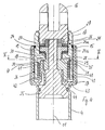
- the fork head 16 is rotatably in the upper end of a receiving sleeve 17 attached.
- On an upper side of a radial inner shoulder 18 of the receiving sleeve 17 are annular first and second brake disks 19, 20 of a first brake device 21 provided.
- the brake disks 19, 20 have Braking surfaces and are each against different End faces 24a, 24b of a ring 24.
- the ring 24 is open pushed an upper end of a receiving body 25.
- Lock nut 27 presses the ring 24 towards the push tube 4. This also makes the position of the first brake disk 19 secured.
- first coupling element 35 is part of a second Braking device 36, which is designed as a loop spring brake is.
- the second braking device 36 is located below of the radial shoulder 18.
- the bottom part 34 With its inside, the bottom part 34 lies against a first one Paragraph 37 of the receiving body 25.
- the bottom part 34 has in the area of Longitudinal movement axis 11 has a recess 38 through which the receiving body 25 is passed (Fig. 4, Fig. 5).
- a flat 39 of its otherwise circular cross-sectional shape lies the receiving body 25 against a corresponding one Flattening of the recess 38 as, among other things 5 can be seen from the cross-sectional illustration is.
- the first coupling element 35 is non-rotatable secured the receiving body 25.
- a claw 41 of a second coupling element 42 arranged between two claws 40 of the first coupling element 35 is at a distance.
- the free ends of the claws 41 thus lie directly on the bottom part 34 of the first coupling element 35 opposite.
- the claws 41 of the second Coupling element 42 run essentially parallel to Longitudinal movement axis 11.
- the claws 41 are on one end Ring section 43 in one piece with the rotating ring 15 connected, the longitudinal extent of which is also essentially is aligned parallel to the claws 40, 41.
- the rotating ring 15 lies with its ring section 43 against another paragraph 44 of the receiving body 25.
- the claws 40, 41 are located thus within the rotating ring 15.
- the claws 40, 41 of both coupling elements 35, 42 are from surrounded a coil spring 47.
- the one shown in Fig. 7 individually Coil spring 47 is with a slight slope wrapped so that successive turns are very lie close to each other, if possible lie against each other.
- a length of the coil spring 47 in the direction of the longitudinal movement axis 11 corresponds approximately to the length of the claws 40, 41st
- An outer surface 48 which acts as a braking surface Coil spring 47 lies against an inner surface 49 of the receiving sleeve 17.
- the two ends 50, 51 of the coil spring 47 bent inwards and between two each Claws 40, 41 of the two coupling elements 35, 42 inserted.
- the two ends 50, 51 act as drivers and can - how is explained in more detail below - by a rotary movement of the coupling elements 35, 42 in contact against side surfaces from claws 40, 41.
- the rotational movement of the threaded nut 10 begins immediately after with the rotating ring 15 the diameter of the coil spring 47 was reduced. Will the rotary motion of the rotating ring 15 continued beyond, so the coil spring 47 of the second coupling element 42 during its rotational movement taken.
- the push tube 4 follows this movement together with the non-rotatable over the receiving body on the push tube connected first coupling element 35 and the coil spring 47.
- the push tube 4 then rotates through the angle of rotation, around which the rotating ring 15 is rotated manually. Will the Rotational movement of the rotating ring 15 is stopped, so this is also the rotation of the coil spring 47 is stopped.
- the push tube 4 has here in the direction of the longitudinal movement axis 11 traveled a distance equal to the distance covered Angle of rotation of the rotating ring 15 corresponds. To with the push pipe The rotating ring 15 can travel 4 longer distances several times be operated. Every rotation angle of the rotating ring 15 is thus assigned a certain distance of the push tube 4.
- the push tube 4 can also be used the (emergency) adjustment device 14 by predetermined Routes are extended, which increases the length of the linear drive increased. This can be provided in particular be when the load is acting as a pull on the linear actuator acts.
- the rotating ring 15 is one of those to be moved To actuate the corresponding angle of rotation, whereby the frictional engagement between the coil spring 47 and the receiving sleeve 17 is in turn released.
- the Rotary ring 15 for this purpose in an opposite to the pressure load To operate in the direction of rotation.
- the force flow of the tensile force runs over the Clevis 16 and the paragraph 18 of the receiving sleeve 17 in the Friction disk 28 and the first brake disk 19. From here the flow of force passes from the ring 24 into the nut 27 and then into the receiving body 25 and thus also into the push tube 4. Unlike a compressive force that is used to retract the push tube - and thus to a reduction in the length of the Linear drive leads is not the second brake disc 20 but the first brake disc 19 is involved in the power flow.
Landscapes
- Engineering & Computer Science (AREA)
- General Engineering & Computer Science (AREA)
- Mechanical Engineering (AREA)
- Transmission Devices (AREA)
- Valve Device For Special Equipments (AREA)
- Fluid-Damping Devices (AREA)
- Knitting Machines (AREA)
Abstract
Description
- Fig. 1
- eine perspektivische Darstellung eines erfindungsgemässen Linearantriebs;
- Fig. 2
- ein lastseitiges Ende des Linearantriebs mit einer Verstelleinrichtung in einer perspektivischen Darstellung;
- Fig. 3
- eine teilweise geschnittene perspektivische Darstellung der Verstelleinrichtung aus Fig. 2;
- Fig. 4
- die Verstelleinrichtung aus Fig. 2 und Fig. 3 in einem Längsschnitt;
- Fig. 5
- ein Querschnitt entlang der Linie V-V in Fig. 4;
- Fig. 6
- ein Kopplungselement einer Bremseinrichtung;
- Fig. 7
- eine Schraubenfeder einer Bremseinrichtung.
Claims (10)
- Linearantrieb mit einer antriebsseitig von einem Motor rotativ antreibbaren Spindel, deren Rotationsbewegung zur Lastseite des Linearantriebs hin in eine translatorische Bewegung eines mit der Spindel wirkverbundenen Schubrohres transformierbar ist, wobei
eine drehfeste Verbindung des Schubrohres mit einem Verbindungsteil, mit dem der Linearantrieb an einer zu verstellenden Last anschliessbar ist, mittels einer Verstelleinrichtung lösbar ist, um eine motorunabhängige Längenänderung des Linearantriebs zu ermöglichen, und wobei
die Verstelleinrichtung mit einer Bremse versehen ist, mit der ein durch eine Verschiebekraft bedingtes Drehmoment vom Schubrohr auf den Verbindungsteil übertragbar ist und eine von der Lastseite eingeleitete Verschiebekraft in Form eines Bremsdrehmomentes zumindest teilweise aufnehmbar ist, dadurch gekennzeichnet, dass
mittels einem Betätigungselement der Verstelleinrichtung (14) bestimmte Verstelllängen des Schubrohres (4) einstellbar sind, um die hierdurch das Schubrohr (4) für eine Bewegung mit zumindest einer Bewegungskomponente entlang der Längsbewegungsachse (11) freigegeben wird, wobei aufgrund der Freigabe das Schubrohr (4) durch eine über den Verbindungsteil auf das Schubrohr (4) wirkenden Verschiebekraft bewegbar ist. - Linearantrieb nach Anspruch 1, dadurch gekennzeichnet, dass das Schubrohr (4) bei Erreichen der voreingestellten Verstelllänge durch die Bremse angehalten wird.
- Linearantrieb nach einem oder beiden der vorhergehenden Ansprüche 1 und 2, gekennzeichnet durch eine Bremse, die mit einer ersten und einer zweiten Bremseinrichtung (21, 36) versehen ist, wobei mit der ersten Bremseinrichtung (21) ein lastabhängiges Bremsmoment erzeugbar ist, das kleiner ist als das durch eine Last aufgebrachte Drehmoment.
- Linearantrieb nach Anspruch 3, gekennzeichnet durch die zweite Bremseinrichtung (36), mit der ein im Wesentlichen lastunabhängiges Bremsmoment erzeugbar ist.
- Linearantrieb nach Anspruch 3 oder 4, dadurch gekennzeichnet, dass das mit beiden Bremseinrichtungen (21, 36) erzeugbare Bremsmoment unabhängig von der jeweiligen Last stets grösser ist als das durch die Last bedingte Drehmoment.
- Linearantrieb nach einem der Ansprüche 3 bis 5, dadurch gekennzeichnet, dass mit einem Betätigungselement der Verstelleinrichtung an einer der beiden Bremseinrichtungen (21, 36) die Verstelllänge des Schubrohres (4) einstellbar ist.
- Linearantrieb nach einem der vorhergehenden Ansprüche, dadurch gekennzeichnet, dass die Bremse eine Schraubenfeder (47) aufweist, deren Bremswirkung durch Reibschluss zwischen ihrer Aussenfläche (48) und einer Bremsfläche erzielbar ist.
- Linearantrieb nach Anspruch 7, dadurch gekennzeichnet, dass die Schraubenfeder (47) um beliebige Drehwinkel drehbar ist.
- Linearantrieb nach Anspruch 7 oder 8, dadurch gekennzeichnet, dass zur Einstellung der Verstelllänge die Schraubenfeder (47) um einen der Verstelllänge entsprechenden Drehwinkel um die Längsbewegungsachse (11) drehbar ist.
- Linearantrieb nach einem der vorhergehenden Ansprüche, dadurch gekennzeichnet, dass die Bremse zumindest zwei ringförmige Bremsflächen aufweist, von denen sich bei einer Zugbelastung die eine Bremsfläche und bei einer Druckbelastung die andere Bremsfläche im Kraftfluss vom Verbindungsteil zum Schubrohr befindet.
Applications Claiming Priority (2)
| Application Number | Priority Date | Filing Date | Title |
|---|---|---|---|
| CH4232003 | 2003-03-14 | ||
| CH4232003 | 2003-03-14 |
Publications (2)
| Publication Number | Publication Date |
|---|---|
| EP1457710A1 true EP1457710A1 (de) | 2004-09-15 |
| EP1457710B1 EP1457710B1 (de) | 2005-09-14 |
Family
ID=32739340
Family Applications (1)
| Application Number | Title | Priority Date | Filing Date |
|---|---|---|---|
| EP04005527A Expired - Lifetime EP1457710B1 (de) | 2003-03-14 | 2004-03-09 | Linearantrieb mit einer Notverstelleinrichtung |
Country Status (4)
| Country | Link |
|---|---|
| EP (1) | EP1457710B1 (de) |
| AT (1) | ATE304672T1 (de) |
| DE (1) | DE502004000062D1 (de) |
| DK (1) | DK1457710T3 (de) |
Cited By (10)
| Publication number | Priority date | Publication date | Assignee | Title |
|---|---|---|---|---|
| EP1637775A1 (de) * | 2004-09-20 | 2006-03-22 | Ab Skf | Linearantrieb mit einer Notverstellmöglichkeit |
| WO2006087365A3 (de) * | 2005-02-17 | 2006-12-21 | Dewert Antriebs Systemtech | Elektromotorischer linearantrieb |
| WO2007025550A1 (en) | 2005-09-02 | 2007-03-08 | Linak A/S | Actuator |
| US7511442B2 (en) * | 2004-10-28 | 2009-03-31 | Ab Skf | Linear drive device |
| WO2009097856A1 (en) * | 2008-02-08 | 2009-08-13 | Linak A/S | Actuator |
| US7779973B2 (en) * | 2006-07-05 | 2010-08-24 | Chen-Hui Ko | Transmission mechanism with the function of the shock absorption |
| CN101253350B (zh) * | 2005-09-02 | 2014-06-11 | 利纳克有限公司 | 致动器 |
| US20140202271A1 (en) * | 2011-04-21 | 2014-07-24 | Dewertokin Gmbh | An electromotive linear drive |
| WO2018042048A1 (en) | 2016-09-05 | 2018-03-08 | Reac Ab | Hoist device comprising a linear actuator with a manual lowering device |
| DE102017207251B4 (de) * | 2017-04-28 | 2025-10-02 | Schaeffler Technologies AG & Co. KG | Teleskopsäule |
Citations (3)
| Publication number | Priority date | Publication date | Assignee | Title |
|---|---|---|---|---|
| EP0685662A2 (de) * | 1994-05-31 | 1995-12-06 | Linak A/S | Linearer Stellantrieb |
| DE19950689A1 (de) * | 1998-10-21 | 2000-11-02 | Okin Ges Fuer Antriebstechnik | Linearantrieb |
| CH692805A5 (de) * | 1998-02-24 | 2002-11-15 | Magnetic Elektromotoren Ag | Antrieb zum Verstellen eines Objektes. |
-
2004
- 2004-03-09 DE DE502004000062T patent/DE502004000062D1/de not_active Expired - Lifetime
- 2004-03-09 DK DK04005527T patent/DK1457710T3/da active
- 2004-03-09 EP EP04005527A patent/EP1457710B1/de not_active Expired - Lifetime
- 2004-03-09 AT AT04005527T patent/ATE304672T1/de not_active IP Right Cessation
Patent Citations (3)
| Publication number | Priority date | Publication date | Assignee | Title |
|---|---|---|---|---|
| EP0685662A2 (de) * | 1994-05-31 | 1995-12-06 | Linak A/S | Linearer Stellantrieb |
| CH692805A5 (de) * | 1998-02-24 | 2002-11-15 | Magnetic Elektromotoren Ag | Antrieb zum Verstellen eines Objektes. |
| DE19950689A1 (de) * | 1998-10-21 | 2000-11-02 | Okin Ges Fuer Antriebstechnik | Linearantrieb |
Cited By (17)
| Publication number | Priority date | Publication date | Assignee | Title |
|---|---|---|---|---|
| EP1637775A1 (de) * | 2004-09-20 | 2006-03-22 | Ab Skf | Linearantrieb mit einer Notverstellmöglichkeit |
| US7511442B2 (en) * | 2004-10-28 | 2009-03-31 | Ab Skf | Linear drive device |
| US8281677B2 (en) | 2005-02-17 | 2012-10-09 | Dewertokin Gmbh | Electromotive linear drive |
| WO2006087365A3 (de) * | 2005-02-17 | 2006-12-21 | Dewert Antriebs Systemtech | Elektromotorischer linearantrieb |
| WO2007025550A1 (en) | 2005-09-02 | 2007-03-08 | Linak A/S | Actuator |
| CN101253350B (zh) * | 2005-09-02 | 2014-06-11 | 利纳克有限公司 | 致动器 |
| AU2006286941B2 (en) * | 2005-09-02 | 2011-06-16 | Linak A/S | Actuator |
| US8186236B2 (en) | 2005-09-02 | 2012-05-29 | Linak A/S | Actuator |
| US7779973B2 (en) * | 2006-07-05 | 2010-08-24 | Chen-Hui Ko | Transmission mechanism with the function of the shock absorption |
| US8234944B2 (en) | 2008-02-08 | 2012-08-07 | Linak A/S | Actuator |
| RU2485370C2 (ru) * | 2008-02-08 | 2013-06-20 | Линак А/С | Привод |
| WO2009097856A1 (en) * | 2008-02-08 | 2009-08-13 | Linak A/S | Actuator |
| US20140202271A1 (en) * | 2011-04-21 | 2014-07-24 | Dewertokin Gmbh | An electromotive linear drive |
| US9404562B2 (en) * | 2011-04-21 | 2016-08-02 | Dewertokin Gmbh | Electromotive linear drive |
| WO2018042048A1 (en) | 2016-09-05 | 2018-03-08 | Reac Ab | Hoist device comprising a linear actuator with a manual lowering device |
| SE541297C2 (en) * | 2016-09-05 | 2019-06-18 | Reac Ab | Hoist device comprising a linear actuator with a manual lowering device |
| DE102017207251B4 (de) * | 2017-04-28 | 2025-10-02 | Schaeffler Technologies AG & Co. KG | Teleskopsäule |
Also Published As
| Publication number | Publication date |
|---|---|
| ATE304672T1 (de) | 2005-09-15 |
| EP1457710B1 (de) | 2005-09-14 |
| DK1457710T3 (da) | 2006-01-30 |
| DE502004000062D1 (de) | 2005-10-20 |
Similar Documents
| Publication | Publication Date | Title |
|---|---|---|
| DE69518195T2 (de) | Linearer Stellantrieb | |
| EP2274177B1 (de) | Fahrwerksaktuator | |
| EP2699815B1 (de) | Elektromotorischer linearantrieb | |
| EP2777136B1 (de) | Linearantrieb für möbel | |
| EP3224497B1 (de) | Scheibenbremse, insbesondere für nutzfahrzeuge | |
| EP3102845B1 (de) | Fahrzeugscheibenbremse | |
| EP1637775B1 (de) | Linearantrieb mit einer Notverstellmöglichkeit | |
| EP0188710B1 (de) | Bremsgestänge für Fahrzeugbremsen | |
| DE102019105560A1 (de) | Linearantrieb | |
| DE202005002585U1 (de) | Elektromotorischer Linearantrieb | |
| EP1457710B1 (de) | Linearantrieb mit einer Notverstelleinrichtung | |
| DE10214670B4 (de) | Bremszuspanneinrichtung mit elektrisch betätigtem Verschleißnachsteller | |
| DE2238632A1 (de) | Vorrichtung zur freigabe einer in zwei richtungen wirksamen bremse oder kupplung mit ruecklaufsperre | |
| EP2636917A1 (de) | Verschleißnachstellvorrichtung für Scheibenbremsen | |
| WO2012037916A1 (de) | Umschlingungsbremsvorrichtung für planetengetriebe und planetengetriebe mit umschlingungsbremsvorrichtung | |
| EP1494907B1 (de) | Bremszuspanneinrichtung mit elektrisch betätigter einrichtung zum not- und hilfslösen | |
| EP1494908B1 (de) | BREMSZUSPANNEINRICHTUNG MIT ELEKTRISCH BETÄTIGTER VERSCHLEISSNACHSTELL- UND NOT- UND HILFSLöSEEINRICHTUNG | |
| DE102005007205B3 (de) | Elektromotorischer Linearantrieb | |
| EP0995714A1 (de) | Sicherheitseinrichtung für einen linearen Gewindetrieb | |
| EP1310702B1 (de) | Bremsvorrichtung für eine rotative Antriebsvorrichtung | |
| DE202013009442U1 (de) | Verschleißnachstellvorrichtung für Scheibenbremsen | |
| EP0499970A2 (de) | Zangenartiges Bremsgestänge, insbesondere für Scheibenbremsen von Schienenfahrzeugen | |
| DE202011110086U1 (de) | Elektromotorischer Linearantrieb, insbesondere zum Verstellen von Liege- und Sitzmöbeln | |
| DE2407259C3 (de) | Bremsbetätigungs- und -lüftvorrichtung | |
| CH340385A (de) | Reibungskupplung mit Ausrückvorrichtung |
Legal Events
| Date | Code | Title | Description |
|---|---|---|---|
| PUAI | Public reference made under article 153(3) epc to a published international application that has entered the european phase |
Free format text: ORIGINAL CODE: 0009012 |
|
| AK | Designated contracting states |
Kind code of ref document: A1 Designated state(s): AT BE BG CH CY CZ DE DK EE ES FI FR GB GR HU IE IT LI LU MC NL PL PT RO SE SI SK TR |
|
| AX | Request for extension of the european patent |
Extension state: AL LT LV MK |
|
| 17P | Request for examination filed |
Effective date: 20040921 |
|
| GRAP | Despatch of communication of intention to grant a patent |
Free format text: ORIGINAL CODE: EPIDOSNIGR1 |
|
| AKX | Designation fees paid |
Designated state(s): AT BE BG CH CY CZ DE DK EE ES FI FR GB GR HU IE IT LI LU MC NL PL PT RO SE SI SK TR |
|
| GRAS | Grant fee paid |
Free format text: ORIGINAL CODE: EPIDOSNIGR3 |
|
| GRAA | (expected) grant |
Free format text: ORIGINAL CODE: 0009210 |
|
| AK | Designated contracting states |
Kind code of ref document: B1 Designated state(s): AT BE BG CH CY CZ DE DK EE ES FI FR GB GR HU IE IT LI LU MC NL PL PT RO SE SI SK TR |
|
| PG25 | Lapsed in a contracting state [announced via postgrant information from national office to epo] |
Ref country code: SK Free format text: LAPSE BECAUSE OF FAILURE TO SUBMIT A TRANSLATION OF THE DESCRIPTION OR TO PAY THE FEE WITHIN THE PRESCRIBED TIME-LIMIT Effective date: 20050914 Ref country code: NL Free format text: LAPSE BECAUSE OF FAILURE TO SUBMIT A TRANSLATION OF THE DESCRIPTION OR TO PAY THE FEE WITHIN THE PRESCRIBED TIME-LIMIT Effective date: 20050914 Ref country code: FI Free format text: LAPSE BECAUSE OF FAILURE TO SUBMIT A TRANSLATION OF THE DESCRIPTION OR TO PAY THE FEE WITHIN THE PRESCRIBED TIME-LIMIT Effective date: 20050914 Ref country code: SI Free format text: LAPSE BECAUSE OF FAILURE TO SUBMIT A TRANSLATION OF THE DESCRIPTION OR TO PAY THE FEE WITHIN THE PRESCRIBED TIME-LIMIT Effective date: 20050914 Ref country code: IT Free format text: LAPSE BECAUSE OF FAILURE TO SUBMIT A TRANSLATION OF THE DESCRIPTION OR TO PAY THE FEE WITHIN THE PRESCRIBED TIME-LIMIT;WARNING: LAPSES OF ITALIAN PATENTS WITH EFFECTIVE DATE BEFORE 2007 MAY HAVE OCCURRED AT ANY TIME BEFORE 2007. THE CORRECT EFFECTIVE DATE MAY BE DIFFERENT FROM THE ONE RECORDED. Effective date: 20050914 Ref country code: PL Free format text: LAPSE BECAUSE OF FAILURE TO SUBMIT A TRANSLATION OF THE DESCRIPTION OR TO PAY THE FEE WITHIN THE PRESCRIBED TIME-LIMIT Effective date: 20050914 Ref country code: CZ Free format text: LAPSE BECAUSE OF FAILURE TO SUBMIT A TRANSLATION OF THE DESCRIPTION OR TO PAY THE FEE WITHIN THE PRESCRIBED TIME-LIMIT Effective date: 20050914 Ref country code: IE Free format text: LAPSE BECAUSE OF FAILURE TO SUBMIT A TRANSLATION OF THE DESCRIPTION OR TO PAY THE FEE WITHIN THE PRESCRIBED TIME-LIMIT Effective date: 20050914 Ref country code: RO Free format text: LAPSE BECAUSE OF FAILURE TO SUBMIT A TRANSLATION OF THE DESCRIPTION OR TO PAY THE FEE WITHIN THE PRESCRIBED TIME-LIMIT Effective date: 20050914 |
|
| REG | Reference to a national code |
Ref country code: GB Ref legal event code: FG4D Free format text: NOT ENGLISH |
|
| REG | Reference to a national code |
Ref country code: CH Ref legal event code: EP |
|
| REG | Reference to a national code |
Ref country code: IE Ref legal event code: FG4D Free format text: LANGUAGE OF EP DOCUMENT: GERMAN |
|
| REF | Corresponds to: |
Ref document number: 502004000062 Country of ref document: DE Date of ref document: 20051020 Kind code of ref document: P |
|
| REG | Reference to a national code |
Ref country code: DE Ref legal event code: R096 Ref document number: 502004000062 Country of ref document: DE Effective date: 20051020 |
|
| PG25 | Lapsed in a contracting state [announced via postgrant information from national office to epo] |
Ref country code: BG Free format text: LAPSE BECAUSE OF FAILURE TO SUBMIT A TRANSLATION OF THE DESCRIPTION OR TO PAY THE FEE WITHIN THE PRESCRIBED TIME-LIMIT Effective date: 20051214 Ref country code: GR Free format text: LAPSE BECAUSE OF FAILURE TO SUBMIT A TRANSLATION OF THE DESCRIPTION OR TO PAY THE FEE WITHIN THE PRESCRIBED TIME-LIMIT Effective date: 20051214 |
|
| REG | Reference to a national code |
Ref country code: SE Ref legal event code: TRGR |
|
| PG25 | Lapsed in a contracting state [announced via postgrant information from national office to epo] |
Ref country code: ES Free format text: LAPSE BECAUSE OF FAILURE TO SUBMIT A TRANSLATION OF THE DESCRIPTION OR TO PAY THE FEE WITHIN THE PRESCRIBED TIME-LIMIT Effective date: 20051225 |
|
| GBT | Gb: translation of ep patent filed (gb section 77(6)(a)/1977) |
Effective date: 20051214 |
|
| REG | Reference to a national code |
Ref country code: CH Ref legal event code: NV Representative=s name: R. A. EGLI & CO. PATENTANWAELTE |
|
| REG | Reference to a national code |
Ref country code: DK Ref legal event code: T3 |
|
| PG25 | Lapsed in a contracting state [announced via postgrant information from national office to epo] |
Ref country code: PT Free format text: LAPSE BECAUSE OF FAILURE TO SUBMIT A TRANSLATION OF THE DESCRIPTION OR TO PAY THE FEE WITHIN THE PRESCRIBED TIME-LIMIT Effective date: 20060214 |
|
| NLV1 | Nl: lapsed or annulled due to failure to fulfill the requirements of art. 29p and 29m of the patents act | ||
| PG25 | Lapsed in a contracting state [announced via postgrant information from national office to epo] |
Ref country code: AT Free format text: LAPSE BECAUSE OF NON-PAYMENT OF DUE FEES Effective date: 20060309 |
|
| PG25 | Lapsed in a contracting state [announced via postgrant information from national office to epo] |
Ref country code: HU Free format text: LAPSE BECAUSE OF FAILURE TO SUBMIT A TRANSLATION OF THE DESCRIPTION OR TO PAY THE FEE WITHIN THE PRESCRIBED TIME-LIMIT Effective date: 20060315 |
|
| PG25 | Lapsed in a contracting state [announced via postgrant information from national office to epo] |
Ref country code: LU Free format text: LAPSE BECAUSE OF NON-PAYMENT OF DUE FEES Effective date: 20060331 Ref country code: BE Free format text: LAPSE BECAUSE OF NON-PAYMENT OF DUE FEES Effective date: 20060331 Ref country code: MC Free format text: LAPSE BECAUSE OF NON-PAYMENT OF DUE FEES Effective date: 20060331 |
|
| REG | Reference to a national code |
Ref country code: IE Ref legal event code: FD4D |
|
| PLBE | No opposition filed within time limit |
Free format text: ORIGINAL CODE: 0009261 |
|
| STAA | Information on the status of an ep patent application or granted ep patent |
Free format text: STATUS: NO OPPOSITION FILED WITHIN TIME LIMIT |
|
| 26N | No opposition filed |
Effective date: 20060615 |
|
| REG | Reference to a national code |
Ref country code: DE Ref legal event code: R097 Ref document number: 502004000062 Country of ref document: DE Effective date: 20060615 |
|
| PG25 | Lapsed in a contracting state [announced via postgrant information from national office to epo] |
Ref country code: FR Free format text: LAPSE BECAUSE OF FAILURE TO SUBMIT A TRANSLATION OF THE DESCRIPTION OR TO PAY THE FEE WITHIN THE PRESCRIBED TIME-LIMIT Effective date: 20061020 |
|
| EN | Fr: translation not filed | ||
| EN | Fr: translation not filed | ||
| BERE | Be: lapsed |
Owner name: A.B. SKF Effective date: 20060331 |
|
| PG25 | Lapsed in a contracting state [announced via postgrant information from national office to epo] |
Ref country code: EE Free format text: LAPSE BECAUSE OF FAILURE TO SUBMIT A TRANSLATION OF THE DESCRIPTION OR TO PAY THE FEE WITHIN THE PRESCRIBED TIME-LIMIT Effective date: 20050914 |
|
| PG25 | Lapsed in a contracting state [announced via postgrant information from national office to epo] |
Ref country code: TR Free format text: LAPSE BECAUSE OF FAILURE TO SUBMIT A TRANSLATION OF THE DESCRIPTION OR TO PAY THE FEE WITHIN THE PRESCRIBED TIME-LIMIT Effective date: 20050914 |
|
| PG25 | Lapsed in a contracting state [announced via postgrant information from national office to epo] |
Ref country code: CY Free format text: LAPSE BECAUSE OF FAILURE TO SUBMIT A TRANSLATION OF THE DESCRIPTION OR TO PAY THE FEE WITHIN THE PRESCRIBED TIME-LIMIT Effective date: 20050914 Ref country code: FR Free format text: LAPSE BECAUSE OF FAILURE TO SUBMIT A TRANSLATION OF THE DESCRIPTION OR TO PAY THE FEE WITHIN THE PRESCRIBED TIME-LIMIT Effective date: 20050914 |
|
| REG | Reference to a national code |
Ref country code: DE Ref legal event code: R082 Ref document number: 502004000062 Country of ref document: DE Representative=s name: HEYERHOFF GEIGER GMBH & CO. KG, DE Ref country code: DE Ref legal event code: R082 Ref document number: 502004000062 Country of ref document: DE Representative=s name: HEYERHOFF GEIGER & PARTNER PATENTANWAELTE PART, DE |
|
| REG | Reference to a national code |
Ref country code: DE Ref legal event code: R081 Ref document number: 502004000062 Country of ref document: DE Owner name: SCHAEFFLER TECHNOLOGIES AG & CO. KG, DE Free format text: FORMER OWNER: AB SKF, GOETEBORG/GOTENBURG, SE Ref country code: DE Ref legal event code: R082 Ref document number: 502004000062 Country of ref document: DE Representative=s name: HEYERHOFF GEIGER & PARTNER PATENTANWAELTE PART, DE Ref country code: DE Ref legal event code: R081 Ref document number: 502004000062 Country of ref document: DE Owner name: EWELLIX AB, SE Free format text: FORMER OWNER: AB SKF, GOETEBORG/GOTENBURG, SE |
|
| REG | Reference to a national code |
Ref country code: GB Ref legal event code: 732E Free format text: REGISTERED BETWEEN 20220519 AND 20220525 |
|
| PGFP | Annual fee paid to national office [announced via postgrant information from national office to epo] |
Ref country code: DK Payment date: 20230323 Year of fee payment: 20 |
|
| PGFP | Annual fee paid to national office [announced via postgrant information from national office to epo] |
Ref country code: SE Payment date: 20230315 Year of fee payment: 20 Ref country code: GB Payment date: 20230323 Year of fee payment: 20 Ref country code: DE Payment date: 20230322 Year of fee payment: 20 |
|
| P01 | Opt-out of the competence of the unified patent court (upc) registered |
Effective date: 20230514 |
|
| PGFP | Annual fee paid to national office [announced via postgrant information from national office to epo] |
Ref country code: CH Payment date: 20230402 Year of fee payment: 20 |
|
| REG | Reference to a national code |
Ref country code: DE Ref legal event code: R071 Ref document number: 502004000062 Country of ref document: DE |
|
| REG | Reference to a national code |
Ref country code: DK Ref legal event code: EUP Expiry date: 20240309 |
|
| REG | Reference to a national code |
Ref country code: CH Ref legal event code: PL |
|
| REG | Reference to a national code |
Ref country code: GB Ref legal event code: PE20 Expiry date: 20240308 |
|
| PG25 | Lapsed in a contracting state [announced via postgrant information from national office to epo] |
Ref country code: GB Free format text: LAPSE BECAUSE OF EXPIRATION OF PROTECTION Effective date: 20240308 |
|
| REG | Reference to a national code |
Ref country code: SE Ref legal event code: EUG |
|
| REG | Reference to a national code |
Ref country code: DE Ref legal event code: R082 Ref document number: 502004000062 Country of ref document: DE Ref country code: DE Ref legal event code: R081 Ref document number: 502004000062 Country of ref document: DE Owner name: SCHAEFFLER TECHNOLOGIES AG & CO. KG, DE Free format text: FORMER OWNER: EWELLIX AB, GOETEBORG, SE |