EP1457627A1 - Double-hinge device of the door of a body of an industrial vehicle and body of an industrial vehicle having such a device - Google Patents
Double-hinge device of the door of a body of an industrial vehicle and body of an industrial vehicle having such a device Download PDFInfo
- Publication number
- EP1457627A1 EP1457627A1 EP03290962A EP03290962A EP1457627A1 EP 1457627 A1 EP1457627 A1 EP 1457627A1 EP 03290962 A EP03290962 A EP 03290962A EP 03290962 A EP03290962 A EP 03290962A EP 1457627 A1 EP1457627 A1 EP 1457627A1
- Authority
- EP
- European Patent Office
- Prior art keywords
- parts
- link
- complementary parts
- door
- axes
- Prior art date
- Legal status (The legal status is an assumption and is not a legal conclusion. Google has not performed a legal analysis and makes no representation as to the accuracy of the status listed.)
- Granted
Links
Images


Classifications
-
- E—FIXED CONSTRUCTIONS
- E05—LOCKS; KEYS; WINDOW OR DOOR FITTINGS; SAFES
- E05D—HINGES OR SUSPENSION DEVICES FOR DOORS, WINDOWS OR WINGS
- E05D3/00—Hinges with pins
- E05D3/06—Hinges with pins with two or more pins
- E05D3/12—Hinges with pins with two or more pins with two parallel pins and one arm
- E05D3/125—Hinges with pins with two or more pins with two parallel pins and one arm specially adapted for vehicles
- E05D3/127—Hinges with pins with two or more pins with two parallel pins and one arm specially adapted for vehicles for vehicle doors
-
- E—FIXED CONSTRUCTIONS
- E05—LOCKS; KEYS; WINDOW OR DOOR FITTINGS; SAFES
- E05Y—INDEXING SCHEME RELATING TO HINGES OR OTHER SUSPENSION DEVICES FOR DOORS, WINDOWS OR WINGS AND DEVICES FOR MOVING WINGS INTO OPEN OR CLOSED POSITION, CHECKS FOR WINGS AND WING FITTINGS NOT OTHERWISE PROVIDED FOR, CONCERNED WITH THE FUNCTIONING OF THE WING
- E05Y2900/00—Application of doors, windows, wings or fittings thereof
- E05Y2900/50—Application of doors, windows, wings or fittings thereof for vehicles
- E05Y2900/53—Application of doors, windows, wings or fittings thereof for vehicles characterised by the type of wing
- E05Y2900/531—Doors
Definitions
- the invention relates to a device for double articulation of door of a body of an industrial vehicle as well as a body of a industrial vehicle comprising such a device.
- the object of the invention is to design a double device joint with better resistance to stress mentioned.
- the object of the invention is achieved with a double device door hinge of a body of an industrial vehicle, comprising two mounting parts intended for mounting the device on the body and on the overhead door respectively and connected together by a link having two ends, each mounting part being connected to the link by a articulation arranged at a corresponding end of the connecting rod, the joints having parallel axes.
- the link is formed by two complementary parts assembled along a median plane perpendicular to the axes of articulation.
- the advantage of the device of the invention is more apparent especially when the two complementary parts are made as forgings or machined parts, which gives them a higher mechanical resistance compared to that of molded parts.
- complementary parts are advantageously provided in a central area of the connecting rod, on the faces intended to be compared during the assembly of the link, of conjugate profiles.
- profiles conjugates can be obtained by providing, for example, on the face of one of the two complementary parts, a part in projection and at the corresponding place on the face of the other part complementary, a set back.
- each of two complementary parts are provided, in the central area, on the faces intended to be opposite, one or two protruding parts and an equal number of recessed parts.
- each of the two additional parts which include in addition to the area central, two end zones intended to receive the axes articulation, is formed at at least one of its two ends opposite so that the end zone extends along a plane parallel to the median plane of the link. Thanks to that arrangement, the rod can receive the mounting part corresponding between the ends opposite the parts complementary.
- the assembly of the two complementary parts is done with at least one connecting element, advantageously using two connecting elements.
- the element (s) are arranged at a distance from each of the two joints of the articulation device.
- the assembly elements are consisting of bolts intended to be placed in drilling in the central area of the parts complementary.
- the number of holes corresponds to the number of assembly elements and the axis of each of these holes is parallel to the axes of articulation.
- the holes are widened on the side where the bolt heads. The shape and dimensions of these enlargements correspond to those of the bolt heads intended to be housed there. So you only need one key to screw and tighten the nuts on the bolts.
- the complementary parts are provided, in the end zones of the link, with bearings intended to receive the axes of the joints.
- bearings can be, for example, cylindrical inserts made of a material synthetic with a low coefficient of friction, such as self-lubricating bearings, or bearings.
- the object of the invention is also achieved with a box of an industrial vehicle with a tilting door, in which the door is attached to the body by a device double articulation described above.
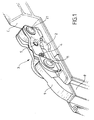
- the double articulation device comprises two pieces of mounting 1, 2 by means of which the device is mounted respectively on a body C of an industrial vehicle and on a tilting door P of this box.
- the two pieces of mounting are connected together by a rod 3 formed by two complementary parts 31, 32 which are assembled along of a median plane M extending perpendicular to the axes of articulation of the device.
- the rod 3 has two ends opposite 33, 34.
- the mounting parts 1, 2 are connected to the link 3 by joints 11, 21 which are arranged at these ends and whose axes 12, 22 are mutually parallel.
- the complementary parts 31, 32 of the link 3 are parts forged. Each of these complementary parts 31, 32 includes a central area and two end areas.
- the central zone is referenced 311 and the two zones ends are referenced 312 and 313, and for part 32, the central zone is referenced 321 and the two end zones are referenced 322 and 323.
- the two complementary parts 31, 32 are each formed at their two ends so that the ends 33, 34 of the link 3 resemble a fork. This is achieved by the fact that the end zones extend along the planes parallel to the median plane M of the link 3, at know the two ends of part 31 extend along a plane N1 located on one side of the median plane M and the two ends of part 32 extend along a plane N2 located on the other side of the median plane M of the link 3. This arrangement allows to mount the mounting parts 1, 2 between the ends in see additional parts 31, 32.
- the axes 12, 22 of the articulations of the device of the invention consist of cylindrical elements housed in orifices 35 to 38 arranged in the end zones 312, 313 and 322, 323 respectively of the complementary parts 31, 32, and pass through holes 13, 23 made in the mounting part 1 and in mounting piece 2 respectively. Axes 12, 22 do not protrude from the outer faces of the link 3.
- the two complementary parts 31, 32 are assembled by means of two connecting elements 4, 5 arranged at a distance from each of the two joints 11, 21 of the double articulation.
- the assembly elements 4, 5 are constituted, in the embodiment shown in the Figures 1 and 2, two bolts housed in holes 316, 318 of the part 31 and 326, 328 of part 32 of the link 3.
- both holes 316 and 328 end, on the outside of the part corresponding 31 or 32, in the form of a hexagonal recess 317 (part 31) and 327 (part 32) intended to receive the head hexagonal of a bolt inserted respectively in the hole 316 and passing through hole 328 on the one hand, and inserted into the hole 326 and passing through hole 318 on the other hand.
- the two complementary parts 31, 32 of the link 3 are also provided, in the central area of each of these parts, on the faces intended to be compared during the assembly of the link, of two projecting parts 314, 324 and two recessed parts 313, 325.
- the projecting parts and the recessed parts have conjugate forms.
- the two projecting parts 314, 324 have the same shape and the same dimensions, as well as the two recessed parts 315 and 325 of each of the two complementary parts 31, 32.
- the two projecting parts are arranged diagonally in the rectangle defined by the set of protruding parts and parts set back from each of the additional parts.
- any other provision of the withdrawing parties and the parties protrusion is possible, especially when it comes to using these parties as a key.
- the axes 12, 22 of the joints 11, 21 can be immobilized in one of the three holes of each of the joints in which the axis is housed.
- the axis 12 of the joint 11 is forcibly inserted and thus immobilized in the hole 13 of the mounting part 1 and will be housed free of rotation in the holes 35, 36 of the complementary parts 31, 32.
- the axis 22 of the articulation 21 is advantageously introduced by force and thus immobilized in the hole 23 in mounting part 2 and housed free to rotate in the holes 37, 38 of the complementary parts 31, 32.
- the free rotation housing is carried out in remaining holes each of which is provided, for example, with a plastic socket 14 having a low coefficient of friction.
Abstract
Description
L'invention concerne un dispositif de double articulation de porte d'une caisse d'un véhicule industriel ainsi qu'une caisse d'un véhicule industriel comportant un tel dispositif.The invention relates to a device for double articulation of door of a body of an industrial vehicle as well as a body of a industrial vehicle comprising such a device.
Les caisses montées sur des véhicules industriels utilisées par exemple pour des travaux publics sont équipées d'une porte basculante arrière. De telles portes sont habituellement constituées de deux vantaux, ce qui permet d'utiliser la porte arrière soit en la fonction dite "deux vantaux", chaque vantail étant alors rabattu sur les côtés de la caisse par le chauffeur avant de benner (basculer) la caisse pour la vider, soit en fonction dite "oscillante", la porte étant alors articulée en partie haute et passant au-dessus du tas constitué par le produit sortant de la caisse lors de l'opération de bennage. L'avantage de l'utilisation d'une double articulation, par rapport à l'utilisation d'une articulation simple, pour la fixation de la porte basculante sur la caisse est qu'elle permet à la porte de se soulever, soit lors du passage au-dessus du terrain par cette dernière configuration, soit lorsque la porte rencontre un obstacle ou lorsqu'elle touche le sol lors du bennage. Toutefois, dans ce dernier cas, il y a malgré tout un risque accru de rupture des articulations.Boxes mounted on industrial vehicles used for example for public works are equipped with a door tilting rear. Such doors are usually consisting of two leaves, which allows the door to be used rear either in the so-called "two leaf" function, each leaf then being folded down on the sides of the body by the driver before dumping (tipping) the box to empty it, either depending called "oscillating", the door then being hinged in the upper part and passing over the pile formed by the product leaving the body during the tipping operation. The advantage of using of a double articulation, compared to the use of a simple articulation, for fixing the tilting door on the is that it allows the door to lift, either when passage above the ground by this last configuration, either when the door encounters an obstacle or when it touches the soil during tipping. However, in the latter case, there is despite a whole increased risk of rupture of the joints.
Le but de l'invention est de concevoir un dispositif de double articulation ayant une meilleure résistance aux contraintes évoquées.The object of the invention is to design a double device joint with better resistance to stress mentioned.
Le but de l'invention est atteint avec un dispositif de double articulation de porte d'une caisse d'un véhicule industriel, comprenant deux pièces de montage destinées au montage du dispositif sur la caisse et sur la porte basculante respectivement et reliées entre elles par une biellette ayant deux extrémités, chaque pièce de montage étant reliée à la biellette par une articulation disposée à une extrémité correspondante de la biellette, les articulations ayant des axes parallèles.The object of the invention is achieved with a double device door hinge of a body of an industrial vehicle, comprising two mounting parts intended for mounting the device on the body and on the overhead door respectively and connected together by a link having two ends, each mounting part being connected to the link by a articulation arranged at a corresponding end of the connecting rod, the joints having parallel axes.
Conformément à l'invention, la biellette est formée par deux parties complémentaires assemblées le long d'un plan médian perpendiculaire aux axes d'articulation. According to the invention, the link is formed by two complementary parts assembled along a median plane perpendicular to the axes of articulation.
La réalisation d'une biellette en deux parties complémentaires permet de séparer la fonction d'axe d'articulation de la fonction montage de la biellette sur les pièces de montage. Grâce à cette disposition de l'invention, les dimensions de certains éléments du dispositif de double articulation résultent à un moindre degré d'un compromis entre les réponses aux différentes contraintes auxquelles la double articulation doit faire face que ce n'est le cas avec les articulations doubles utilisés avant l'invention. En effet, la séparation des deux fonctions est obtenue en utilisant les axes d'articulation exclusivement dans cette fonction et en prévoyant sur la biellette des moyens distincts d'assemblage. De plus, cette disposition de l'invention permet d'immobiliser les axes des articulations soit sur les pièces de montage, soit sur l'une des deux parties complémentaires de la biellette. Et dans l'ensemble, les moyens d'assemblage de la biellette sont formés de façon que l'assemblage de la biellette se fait en même temps que l'assemblage du dispositif de double articulation selon l'invention, comme cela sera décrit en détail plus loin.The realization of a link in two parts separate the articulation axis function of the rod mounting function on the mounting parts. Thanks to this arrangement of the invention, the dimensions of certain elements of the double articulation device result in a lesser degree of a compromise between responses to different constraints to which the double articulation must make that this is the case with the double joints used before the invention. Indeed, the separation of the two functions is obtained by using the hinge pins exclusively in this function and by providing separate means on the link assembly. In addition, this arrangement of the invention allows to immobilize the axes of the joints either on the parts of mounting, either on one of the two complementary parts of the link. And overall, the means of assembling the rod are formed so that the assembly of the rod is done at the same time as assembling the double device articulation according to the invention, as will be described in detail further.
L'avantage du dispositif de l'invention ressort plus particulièrement lorsque les deux parties complémentaires sont réalisées en tant que pièces forgées ou pièces usinées, ce qui leur confère une résistance mécanique plus élevée par rapport à celle de pièces moulées.The advantage of the device of the invention is more apparent especially when the two complementary parts are made as forgings or machined parts, which gives them a higher mechanical resistance compared to that of molded parts.
Afin que les deux parties complémentaires de la biellette ne risquent pas de se décaler l'une par rapport à l'autre dans le sens de leur longueur, et afin d'empêcher aussi des effets de cisaillement aussi bien sur les axes d'articulation que sur les moyens d'assemblage de la biellette, les parties complémentaires sont pourvues avantageusement dans une zone centrale de la biellette, sur les faces destinées à être mises en regard lors de l'assemblage de la biellette, de profils conjugués. De tels profils conjugués peuvent être obtenus en prévoyant, par exemple, sur la face de l'une des deux parties complémentaires, une partie en saillie et à l'endroit correspondant sur la face de l'autre partie complémentaire, une partie en retrait. En variante, chacune des deux parties complémentaires est pourvue, dans la zone centrale, sur les faces destinées à être mises en regard, d'une ou de deux parties en saillie et d'un nombre égal de parties en retrait.So that the two complementary parts of the link do not not likely to shift relative to each other in the direction of their length, and in order to also prevent effects of shear both on the articulation axes and on the connecting rod assembly means, complementary parts are advantageously provided in a central area of the connecting rod, on the faces intended to be compared during the assembly of the link, of conjugate profiles. Such profiles conjugates can be obtained by providing, for example, on the face of one of the two complementary parts, a part in projection and at the corresponding place on the face of the other part complementary, a set back. Alternatively, each of two complementary parts are provided, in the central area, on the faces intended to be opposite, one or two protruding parts and an equal number of recessed parts.
Selon une autre caractéristique de l'invention, chacune des deux parties complémentaires qui comprennent outre la zone centrale, deux zones d'extrémité destinées à recevoir les axes d'articulation, est formée à au moins une de ses deux extrémités opposées de façon que la zone d'extrémité s'étende le long d'un plan parallèle au plan médian de la biellette. Grâce à cette disposition, la biellette peut recevoir la pièce de montage correspondante entre les extrémités en regard des parties complémentaires.According to another characteristic of the invention, each of the two additional parts which include in addition to the area central, two end zones intended to receive the axes articulation, is formed at at least one of its two ends opposite so that the end zone extends along a plane parallel to the median plane of the link. Thanks to that arrangement, the rod can receive the mounting part corresponding between the ends opposite the parts complementary.
L'assemblage des deux parties complémentaires est fait moyennant au moins un élément d'assemblage, avantageusement moyennant deux éléments d'assemblage. Le ou les éléments d'assemblage sont disposés à une distance de chacune des deux articulations du dispositif d'articulation.The assembly of the two complementary parts is done with at least one connecting element, advantageously using two connecting elements. The element (s) are arranged at a distance from each of the two joints of the articulation device.
Avantageusement, les éléments d'assemblage sont constitués par des boulons destinés à être mis en place dans des perçages pratiqués dans la zone centrale des parties complémentaires. Le nombre de perçages correspond au nombre d'éléments d'assemblage et l'axe de chacun de ces perçages est parallèle aux axes d'articulation. Pour faciliter le montage des boulons, les perçages sont élargis du côté où sont logées les têtes des boulons. La forme et les dimensions de ces élargissements correspondent à celles des têtes de boulons destinées à y être logées. Ainsi, on n'a besoin que d'une seule clé pour visser et serrer les écrous sur les boulons.Advantageously, the assembly elements are consisting of bolts intended to be placed in drilling in the central area of the parts complementary. The number of holes corresponds to the number of assembly elements and the axis of each of these holes is parallel to the axes of articulation. To facilitate the mounting of bolts, the holes are widened on the side where the bolt heads. The shape and dimensions of these enlargements correspond to those of the bolt heads intended to be housed there. So you only need one key to screw and tighten the nuts on the bolts.
Avantageusement, les parties complémentaires sont pourvues, dans les zones d'extrémité de la biellette, de paliers destinés à recevoir les axes des articulations. Ces paliers peuvent être, par exemple, des inserts cylindriques réalisés en une matière synthétique ayant un faible coefficient de frottement, tels des coussinets auto-lubrifiants, ou des roulements. Advantageously, the complementary parts are provided, in the end zones of the link, with bearings intended to receive the axes of the joints. These bearings can be, for example, cylindrical inserts made of a material synthetic with a low coefficient of friction, such as self-lubricating bearings, or bearings.
Le but de l'invention est également atteint avec une caisse d'un véhicule industriel comportant une porte basculante, dans laquelle la porte est attachée à la caisse par un dispositif de double articulation décrit ci-avant.The object of the invention is also achieved with a box of an industrial vehicle with a tilting door, in which the door is attached to the body by a device double articulation described above.
D'autres caractéristiques et avantages de l'invention
ressortiront de la description ci-après d'un mode de réalisation de
l'invention, cette description étant faite en référence aux dessins
dans lesquels:
Le dispositif de double articulation comprend deux pièces de
montage 1, 2 moyennant lesquelles le dispositif est monté
respectivement sur une caisse C d'un véhicule industriel et sur
une porte basculante P de cette caisse. Les deux pièces de
montage sont reliées entre elles par une biellette 3 formée par
deux parties complémentaires 31, 32 qui sont assemblées le long
d'un plan médian M s'étendant perpendiculairement aux axes
d'articulation du dispositif. La biellette 3 a deux extrémités
opposées 33, 34. Les pièces de montages 1, 2 sont reliées à la
biellette 3 par des articulations 11, 21 qui sont disposées à ces
extrémités et dont les axes 12, 22 sont parallèles entre eux. Les
parties complémentaires 31, 32 de la biellette 3 sont des pièces
forgées. Chacune de ces parties complémentaires 31, 32
comprend une zone centrale et deux zones d'extrémités. Pour la
partie 31, la zone centrale est référencée 311 et les deux zones
d'extrémités sont référencées 312 et 313, et pour la partie 32, la
zone centrale est référencée 321 et les deux zones d'extrémités
sont référencées 322 et 323. Les deux parties complémentaires
31, 32 sont formées chacune à leurs deux extrémités de façon que
les extrémités 33, 34 de la biellette 3 ressemblent à une fourche.
Ceci est obtenu par le fait que les zones d'extrémités s'étendent
le long des plans parallèles au plan médian M de la biellette 3, à
savoir les deux extrémités de la partie 31 s'étendent le long d'un
plan N1 situé d'un côté du plan médian M et les deux extrémités
de la partie 32 s'étendent le long d'un plan N2 situé de l'autre
côté du plan médian M de la biellette 3. Cette disposition permet
de monter les pièces de montage 1, 2 entre les extrémités en
regard des parties complémentaires 31, 32.The double articulation device comprises two pieces of
mounting 1, 2 by means of which the device is mounted
respectively on a body C of an industrial vehicle and on
a tilting door P of this box. The two pieces of
mounting are connected together by a
Les axes 12, 22 des articulations du dispositif de l'invention
sont constituées par des éléments cylindriques logés dans des
orifices 35 à 38 disposés dans les zones d'extrémité 312, 313 et
322, 323 respectivement des pièces complémentaires 31, 32, et
traversent des orifices 13, 23 pratiqués dans la pièce de montage
1 et dans la pièce de montage 2 respectivement. Les axes 12, 22
ne dépassent pas des faces extérieures de la biellette 3.The
Les deux parties complémentaires 31, 32 sont assemblées
moyennant deux éléments d'assemblage 4, 5 disposés à une
distance de chacune des deux articulations 11, 21 du dispositif de
double articulation. Les éléments d'assemblage 4, 5 sont
constitués, dans le mode de réalisation représenté sur les Figures
1 et 2, de deux boulons logés dans des perçages 316, 318 de la
partie 31 et 326, 328 de la partie 32 de la biellette 3. Afin de
faciliter le montage des éléments d'assemblage 4, 5, les deux
perçages 316 et 328 se terminent, à la face extérieure de la partie
correspondante 31 ou 32, sous la forme d'un évidement hexagonal
317 (partie 31) et 327 (partie 32) destiné à recevoir la tête
hexagonale d'un boulon inséré respectivement dans le perçage
316 et traversant le perçage 328 d'une part, et inséré dans le
perçage 326 et traversant le perçage 318 d'autre part.The two
Les deux parties complémentaires 31, 32 de la biellette 3
sont par ailleurs pourvues, dans la zone centrale de chacune de
ces parties, sur les faces destinées à être mises en regard lors de
l'assemblage de la biellette, de deux parties en saillie 314, 324 et
deux parties en retrait 313, 325. Les parties en saillie et les
parties en retrait ont des formes conjuguées.The two
Grâce à cette disposition de l'invention des forces
longitudinales agissant sur la biellette 3 à partir de l'un des deux
axes d'articulation 12, 22 vers l'autre axe et vice-versa sont
supportées entièrement par l'ensemble des parties en retrait et
des parties en saillie et n'exercent notamment pas d'effet de
cisaillement sur les boulons 4, 5.Thanks to this arrangement of the invention of forces
longitudinal acting on the
Dans l'exemple de réalisation représenté sur la Figure 3, les
deux parties en saillie 314, 324 ont la même forme et les mêmes
dimensions, de même que les deux parties en retrait 315 et 325
de chacune des deux parties complémentaires 31, 32. De plus, les
deux parties en saillie sont disposées en diagonales dans le
rectangle défini par l'ensemble des parties en saillie et des parties
en retrait de chacune des parties complémentaires. Toutefois,
toute autre disposition des parties en retrait et des parties en
saillie est possible, notamment lorsqu'il s'agit de se servir de ces
parties comme détrompeur.In the embodiment shown in Figure 3, the
two projecting
Pour tirer le meilleur profit des dispositions de la présente
invention, les axes 12, 22 des articulations 11, 21 peuvent être
immobilisés dans un des trois perçages de chacune des
articulations dans lesquelles l'axe est logé. Avantageusement,
l'axe 12 de l'articulation 11 est inséré de force et ainsi immobilisé
dans le perçage 13 de la pièce de montage 1 et sera logé libre de
rotation dans les perçages 35, 36 des parties complémentaires 31,
32. De manière analogue, l'axe 22 de l'articulation 21 est
avantageusement introduit de force et ainsi immobilisé dans le
perçage 23 de la pièce de montage 2 et logé libre de rotation dans
les perçages 37, 38 des parties complémentaires 31, 32.To make the most of the provisions of this
invention, the
Toutefois, il est également concevable, sans sortir du cadre
de la présente invention, d'insérer de force et d'immobiliser les
axes 12, 22 dans un des perçages des parties complémentaires
31, 32, par exemple dans les perçages 35, 38 de la partie 31.However, it is also conceivable, without departing from the framework
of the present invention, forcibly inserting and immobilizing the
Quelle que soit la variante choisie pour l'immobilisation des
axes 12, 22, le logement libre de rotation est effectué dans des
perçages restants dont chacun est pourvu, par exemple, d'une
douille 14 en matière plastique ayant un faible coefficient de
frottement.Whatever variant is chosen for immobilizing
Claims (11)
caractérisé en ce que la biellette (3) est formée par deux parties complémentaires (31, 32) assemblées le long d'un plan médian (M) perpendiculaire aux axes d'articulation (12, 22).Device for double articulation of the door of a body of an industrial vehicle, comprising two mounting parts (1, 2) intended for mounting the device respectively on the body and on the door and connected together by a connecting rod (3) having two ends (33, 34), each mounting part (1, 2) being connected to the link (3) by a joint (11, 21) disposed at a corresponding end of the link, the joints (11, 21) having parallel axes (12, 22),
characterized in that the link (3) is formed by two complementary parts (31, 32) assembled along a median plane (M) perpendicular to the axes of articulation (12, 22).
Applications Claiming Priority (2)
| Application Number | Priority Date | Filing Date | Title |
|---|---|---|---|
| FR0303196A FR2852348B1 (en) | 2003-03-14 | 2003-03-14 | DEVICE FOR DOUBLE ARTICULATING THE DOOR OF A BOX OF AN INDUSTRIAL VEHICLE AND CASE OF AN INDUSTRIAL VEHICLE COMPRISING SUCH A DEVICE |
| FR0303196 | 2003-03-14 |
Publications (2)
| Publication Number | Publication Date |
|---|---|
| EP1457627A1 true EP1457627A1 (en) | 2004-09-15 |
| EP1457627B1 EP1457627B1 (en) | 2008-11-12 |
Family
ID=32749799
Family Applications (1)
| Application Number | Title | Priority Date | Filing Date |
|---|---|---|---|
| EP03290962A Expired - Lifetime EP1457627B1 (en) | 2003-03-14 | 2003-04-17 | Double-hinge device of the door of a body of an industrial vehicle and body of an industrial vehicle having such a device |
Country Status (6)
| Country | Link |
|---|---|
| EP (1) | EP1457627B1 (en) |
| AT (1) | ATE414206T1 (en) |
| DE (1) | DE60324657D1 (en) |
| ES (1) | ES2316700T3 (en) |
| FR (1) | FR2852348B1 (en) |
| PT (1) | PT1457627E (en) |
Cited By (1)
| Publication number | Priority date | Publication date | Assignee | Title |
|---|---|---|---|---|
| US10233819B2 (en) | 2013-05-03 | 2019-03-19 | Deere & Company | Dual-pivot hinge for fan |
Citations (3)
| Publication number | Priority date | Publication date | Assignee | Title |
|---|---|---|---|---|
| US2621359A (en) * | 1945-09-15 | 1952-12-16 | Curtiss Wright Corp | Hinge construction |
| DE19613092A1 (en) * | 1995-03-31 | 1996-10-31 | Aghito Rag Dino S P A | Hinge for cargo door |
| WO2000071846A1 (en) * | 1999-05-24 | 2000-11-30 | Tecnologia S.A.S. Di Valentino Brazzale & C. | Articulated wide-angle hinge for doors and the like |
-
2003
- 2003-03-14 FR FR0303196A patent/FR2852348B1/en not_active Expired - Fee Related
- 2003-04-17 ES ES03290962T patent/ES2316700T3/en not_active Expired - Lifetime
- 2003-04-17 DE DE60324657T patent/DE60324657D1/en not_active Expired - Fee Related
- 2003-04-17 EP EP03290962A patent/EP1457627B1/en not_active Expired - Lifetime
- 2003-04-17 PT PT03290962T patent/PT1457627E/en unknown
- 2003-04-17 AT AT03290962T patent/ATE414206T1/en not_active IP Right Cessation
Patent Citations (3)
| Publication number | Priority date | Publication date | Assignee | Title |
|---|---|---|---|---|
| US2621359A (en) * | 1945-09-15 | 1952-12-16 | Curtiss Wright Corp | Hinge construction |
| DE19613092A1 (en) * | 1995-03-31 | 1996-10-31 | Aghito Rag Dino S P A | Hinge for cargo door |
| WO2000071846A1 (en) * | 1999-05-24 | 2000-11-30 | Tecnologia S.A.S. Di Valentino Brazzale & C. | Articulated wide-angle hinge for doors and the like |
Cited By (1)
| Publication number | Priority date | Publication date | Assignee | Title |
|---|---|---|---|---|
| US10233819B2 (en) | 2013-05-03 | 2019-03-19 | Deere & Company | Dual-pivot hinge for fan |
Also Published As
| Publication number | Publication date |
|---|---|
| ES2316700T3 (en) | 2009-04-16 |
| FR2852348B1 (en) | 2006-02-17 |
| PT1457627E (en) | 2009-02-23 |
| EP1457627B1 (en) | 2008-11-12 |
| FR2852348A1 (en) | 2004-09-17 |
| ATE414206T1 (en) | 2008-11-15 |
| DE60324657D1 (en) | 2008-12-24 |
Similar Documents
| Publication | Publication Date | Title |
|---|---|---|
| WO2008102080A1 (en) | Device capable of modulation by expansion or compaction for forming a protection and transport structure at the back and at the height of the roof of the passenger compartment of an automotive vehicle | |
| WO2008096251A1 (en) | Compact elastic hinge for spectacle frames | |
| FR2910393A1 (en) | Slider for motor vehicle seat, has adjusting device including rigid retaining device provided with upper part projected with respect to side opening and base part inserted in internal space through side opening | |
| EP1047981B1 (en) | Wristwatch quick fixing device | |
| EP1457627B1 (en) | Double-hinge device of the door of a body of an industrial vehicle and body of an industrial vehicle having such a device | |
| FR2609883A1 (en) | Toilet lid and seat with hydraulic damping elements | |
| FR2868378A1 (en) | Windshield wiper blade for vehicle, has three guiding blocks guiding and locking windshield wiper arm in longitudinal direction of wiper blade, only when arm is in blade operating position | |
| WO2020233878A1 (en) | Arrangement for mounting an optical system on a body element of a vehicle | |
| FR2802966A1 (en) | MOTOR VEHICLE REAR DOOR HINGE | |
| EP2173953B1 (en) | Connecting device providing the connection between a motor vehicle door latch and lock | |
| EP1182092B1 (en) | Arrangement for mounting an electrical unit in a vehicle | |
| FR2687745A1 (en) | DEVICE FOR JOINING ONE AGAINST THE OTHER TWO RIGID PLATES. | |
| FR2841002A1 (en) | Hinges for spectacles frames have an elastic block with a holding groove to engage with the ear piece and lens bar in one of two position, held in place by elastic pads to prevent accidental dismantling | |
| FR2653929A1 (en) | KEY ACTUATOR MOBILE FOR SAFETY SWITCH. | |
| EP0708871B1 (en) | Louvre window | |
| EP0623837B1 (en) | Resilient hinge for spectacles | |
| EP1106846A1 (en) | Device for reversibly immobilizing a shaft by means of a tangential locking pin | |
| FR2827832A1 (en) | PLOW TYPE ANCHOR | |
| FR2581118A1 (en) | Demountable hinge, especially for motor vehicles | |
| FR2698944A1 (en) | Gear motor. | |
| FR2842143A1 (en) | Automobile door comprises support fitted with hinge around first axis fixed to bodywork and door fitted on first side with second hinge around second axis, second door edge located between hinges | |
| EP2167736A2 (en) | Highways device with support frame and crown element such as a manhole cover or lid mounted to hinge on the frame | |
| EP0670567B1 (en) | Marking device for formed supports for a variety of objects | |
| EP0566443A1 (en) | Device for attaching a windscreen wiper blade on a wiper arm | |
| FR2704268A1 (en) | Hinge with a pin having a variable position |
Legal Events
| Date | Code | Title | Description |
|---|---|---|---|
| PUAI | Public reference made under article 153(3) epc to a published international application that has entered the european phase |
Free format text: ORIGINAL CODE: 0009012 |
|
| AK | Designated contracting states |
Kind code of ref document: A1 Designated state(s): AT BE BG CH CY CZ DE DK EE ES FI FR GB GR HU IE IT LI LU MC NL PT RO SE SI SK TR |
|
| AX | Request for extension of the european patent |
Extension state: AL LT LV MK |
|
| 17P | Request for examination filed |
Effective date: 20050315 |
|
| AKX | Designation fees paid |
Designated state(s): AT BE BG CH CY CZ DE DK EE ES FI FR GB GR HU IE IT LI LU MC NL PT RO SE SI SK TR |
|
| 17Q | First examination report despatched |
Effective date: 20070323 |
|
| RAP1 | Party data changed (applicant data changed or rights of an application transferred) |
Owner name: BENALU |
|
| GRAP | Despatch of communication of intention to grant a patent |
Free format text: ORIGINAL CODE: EPIDOSNIGR1 |
|
| GRAS | Grant fee paid |
Free format text: ORIGINAL CODE: EPIDOSNIGR3 |
|
| GRAA | (expected) grant |
Free format text: ORIGINAL CODE: 0009210 |
|
| AK | Designated contracting states |
Kind code of ref document: B1 Designated state(s): AT BE BG CH CY CZ DE DK EE ES FI FR GB GR HU IE IT LI LU MC NL PT RO SE SI SK TR |
|
| REG | Reference to a national code |
Ref country code: GB Ref legal event code: FG4D Free format text: NOT ENGLISH |
|
| REG | Reference to a national code |
Ref country code: CH Ref legal event code: EP |
|
| REG | Reference to a national code |
Ref country code: IE Ref legal event code: FG4D Free format text: LANGUAGE OF EP DOCUMENT: FRENCH |
|
| REF | Corresponds to: |
Ref document number: 60324657 Country of ref document: DE Date of ref document: 20081224 Kind code of ref document: P |
|
| REG | Reference to a national code |
Ref country code: CH Ref legal event code: NV Representative=s name: ABREMA AGENCE BREVET ET MARQUES, GANGUILLET |
|
| REG | Reference to a national code |
Ref country code: PT Ref legal event code: SC4A Free format text: AVAILABILITY OF NATIONAL TRANSLATION Effective date: 20090212 |
|
| REG | Reference to a national code |
Ref country code: ES Ref legal event code: FG2A Ref document number: 2316700 Country of ref document: ES Kind code of ref document: T3 |
|
| PG25 | Lapsed in a contracting state [announced via postgrant information from national office to epo] |
Ref country code: AT Free format text: LAPSE BECAUSE OF FAILURE TO SUBMIT A TRANSLATION OF THE DESCRIPTION OR TO PAY THE FEE WITHIN THE PRESCRIBED TIME-LIMIT Effective date: 20081112 |
|
| PG25 | Lapsed in a contracting state [announced via postgrant information from national office to epo] |
Ref country code: SI Free format text: LAPSE BECAUSE OF FAILURE TO SUBMIT A TRANSLATION OF THE DESCRIPTION OR TO PAY THE FEE WITHIN THE PRESCRIBED TIME-LIMIT Effective date: 20081112 Ref country code: FI Free format text: LAPSE BECAUSE OF FAILURE TO SUBMIT A TRANSLATION OF THE DESCRIPTION OR TO PAY THE FEE WITHIN THE PRESCRIBED TIME-LIMIT Effective date: 20081112 |
|
| PGFP | Annual fee paid to national office [announced via postgrant information from national office to epo] |
Ref country code: PT Payment date: 20090326 Year of fee payment: 7 |
|
| PGFP | Annual fee paid to national office [announced via postgrant information from national office to epo] |
Ref country code: CH Payment date: 20090325 Year of fee payment: 7 |
|
| REG | Reference to a national code |
Ref country code: IE Ref legal event code: FD4D |
|
| PG25 | Lapsed in a contracting state [announced via postgrant information from national office to epo] |
Ref country code: BG Free format text: LAPSE BECAUSE OF FAILURE TO SUBMIT A TRANSLATION OF THE DESCRIPTION OR TO PAY THE FEE WITHIN THE PRESCRIBED TIME-LIMIT Effective date: 20090212 Ref country code: IE Free format text: LAPSE BECAUSE OF FAILURE TO SUBMIT A TRANSLATION OF THE DESCRIPTION OR TO PAY THE FEE WITHIN THE PRESCRIBED TIME-LIMIT Effective date: 20081112 Ref country code: DK Free format text: LAPSE BECAUSE OF FAILURE TO SUBMIT A TRANSLATION OF THE DESCRIPTION OR TO PAY THE FEE WITHIN THE PRESCRIBED TIME-LIMIT Effective date: 20081112 Ref country code: EE Free format text: LAPSE BECAUSE OF FAILURE TO SUBMIT A TRANSLATION OF THE DESCRIPTION OR TO PAY THE FEE WITHIN THE PRESCRIBED TIME-LIMIT Effective date: 20081112 |
|
| PGFP | Annual fee paid to national office [announced via postgrant information from national office to epo] |
Ref country code: BE Payment date: 20090324 Year of fee payment: 7 Ref country code: ES Payment date: 20090407 Year of fee payment: 7 |
|
| PG25 | Lapsed in a contracting state [announced via postgrant information from national office to epo] |
Ref country code: SE Free format text: LAPSE BECAUSE OF FAILURE TO SUBMIT A TRANSLATION OF THE DESCRIPTION OR TO PAY THE FEE WITHIN THE PRESCRIBED TIME-LIMIT Effective date: 20090212 Ref country code: CZ Free format text: LAPSE BECAUSE OF FAILURE TO SUBMIT A TRANSLATION OF THE DESCRIPTION OR TO PAY THE FEE WITHIN THE PRESCRIBED TIME-LIMIT Effective date: 20081112 |
|
| PGFP | Annual fee paid to national office [announced via postgrant information from national office to epo] |
Ref country code: DE Payment date: 20090504 Year of fee payment: 7 Ref country code: FR Payment date: 20090428 Year of fee payment: 7 Ref country code: IT Payment date: 20090331 Year of fee payment: 7 Ref country code: NL Payment date: 20090326 Year of fee payment: 7 |
|
| PLBE | No opposition filed within time limit |
Free format text: ORIGINAL CODE: 0009261 |
|
| STAA | Information on the status of an ep patent application or granted ep patent |
Free format text: STATUS: NO OPPOSITION FILED WITHIN TIME LIMIT |
|
| PG25 | Lapsed in a contracting state [announced via postgrant information from national office to epo] |
Ref country code: SK Free format text: LAPSE BECAUSE OF FAILURE TO SUBMIT A TRANSLATION OF THE DESCRIPTION OR TO PAY THE FEE WITHIN THE PRESCRIBED TIME-LIMIT Effective date: 20081112 |
|
| 26N | No opposition filed |
Effective date: 20090813 |
|
| GBPC | Gb: european patent ceased through non-payment of renewal fee |
Effective date: 20090417 |
|
| PG25 | Lapsed in a contracting state [announced via postgrant information from national office to epo] |
Ref country code: GB Free format text: LAPSE BECAUSE OF NON-PAYMENT OF DUE FEES Effective date: 20090417 Ref country code: MC Free format text: LAPSE BECAUSE OF NON-PAYMENT OF DUE FEES Effective date: 20090430 |
|
| PG25 | Lapsed in a contracting state [announced via postgrant information from national office to epo] |
Ref country code: RO Free format text: LAPSE BECAUSE OF FAILURE TO SUBMIT A TRANSLATION OF THE DESCRIPTION OR TO PAY THE FEE WITHIN THE PRESCRIBED TIME-LIMIT Effective date: 20081112 |
|
| PG25 | Lapsed in a contracting state [announced via postgrant information from national office to epo] |
Ref country code: GR Free format text: LAPSE BECAUSE OF FAILURE TO SUBMIT A TRANSLATION OF THE DESCRIPTION OR TO PAY THE FEE WITHIN THE PRESCRIBED TIME-LIMIT Effective date: 20090213 |
|
| BERE | Be: lapsed |
Owner name: BENALU Effective date: 20100430 |
|
| REG | Reference to a national code |
Ref country code: NL Ref legal event code: V1 Effective date: 20101101 |
|
| REG | Reference to a national code |
Ref country code: CH Ref legal event code: PL |
|
| REG | Reference to a national code |
Ref country code: FR Ref legal event code: ST Effective date: 20101230 |
|
| PG25 | Lapsed in a contracting state [announced via postgrant information from national office to epo] |
Ref country code: NL Free format text: LAPSE BECAUSE OF NON-PAYMENT OF DUE FEES Effective date: 20101101 |
|
| PG25 | Lapsed in a contracting state [announced via postgrant information from national office to epo] |
Ref country code: DE Free format text: LAPSE BECAUSE OF NON-PAYMENT OF DUE FEES Effective date: 20101103 Ref country code: CH Free format text: LAPSE BECAUSE OF NON-PAYMENT OF DUE FEES Effective date: 20100430 Ref country code: PT Free format text: LAPSE BECAUSE OF NON-PAYMENT OF DUE FEES Effective date: 20101018 Ref country code: LI Free format text: LAPSE BECAUSE OF NON-PAYMENT OF DUE FEES Effective date: 20100430 |
|
| PG25 | Lapsed in a contracting state [announced via postgrant information from national office to epo] |
Ref country code: IT Free format text: LAPSE BECAUSE OF NON-PAYMENT OF DUE FEES Effective date: 20100417 Ref country code: BE Free format text: LAPSE BECAUSE OF NON-PAYMENT OF DUE FEES Effective date: 20100430 |
|
| PG25 | Lapsed in a contracting state [announced via postgrant information from national office to epo] |
Ref country code: LU Free format text: LAPSE BECAUSE OF NON-PAYMENT OF DUE FEES Effective date: 20090417 |
|
| PG25 | Lapsed in a contracting state [announced via postgrant information from national office to epo] |
Ref country code: HU Free format text: LAPSE BECAUSE OF FAILURE TO SUBMIT A TRANSLATION OF THE DESCRIPTION OR TO PAY THE FEE WITHIN THE PRESCRIBED TIME-LIMIT Effective date: 20090513 |
|
| REG | Reference to a national code |
Ref country code: ES Ref legal event code: FD2A Effective date: 20110711 |
|
| PG25 | Lapsed in a contracting state [announced via postgrant information from national office to epo] |
Ref country code: ES Free format text: LAPSE BECAUSE OF NON-PAYMENT OF DUE FEES Effective date: 20110629 |
|
| PG25 | Lapsed in a contracting state [announced via postgrant information from national office to epo] |
Ref country code: TR Free format text: LAPSE BECAUSE OF FAILURE TO SUBMIT A TRANSLATION OF THE DESCRIPTION OR TO PAY THE FEE WITHIN THE PRESCRIBED TIME-LIMIT Effective date: 20081112 |
|
| PG25 | Lapsed in a contracting state [announced via postgrant information from national office to epo] |
Ref country code: ES Free format text: LAPSE BECAUSE OF NON-PAYMENT OF DUE FEES Effective date: 20100418 Ref country code: CY Free format text: LAPSE BECAUSE OF FAILURE TO SUBMIT A TRANSLATION OF THE DESCRIPTION OR TO PAY THE FEE WITHIN THE PRESCRIBED TIME-LIMIT Effective date: 20081112 |
|
| PG25 | Lapsed in a contracting state [announced via postgrant information from national office to epo] |
Ref country code: FR Free format text: LAPSE BECAUSE OF NON-PAYMENT OF DUE FEES Effective date: 20100430 |