EP1457588A1 - Anodization method and treating device therefor - Google Patents
Anodization method and treating device therefor Download PDFInfo
- Publication number
- EP1457588A1 EP1457588A1 EP02783813A EP02783813A EP1457588A1 EP 1457588 A1 EP1457588 A1 EP 1457588A1 EP 02783813 A EP02783813 A EP 02783813A EP 02783813 A EP02783813 A EP 02783813A EP 1457588 A1 EP1457588 A1 EP 1457588A1
- Authority
- EP
- European Patent Office
- Prior art keywords
- oxide film
- water
- electrolytic solution
- carbon dioxide
- anodic oxidation
- Prior art date
- Legal status (The legal status is an assumption and is not a legal conclusion. Google has not performed a legal analysis and makes no representation as to the accuracy of the status listed.)
- Granted
Links
Images


Classifications
-
- C—CHEMISTRY; METALLURGY
- C25—ELECTROLYTIC OR ELECTROPHORETIC PROCESSES; APPARATUS THEREFOR
- C25D—PROCESSES FOR THE ELECTROLYTIC OR ELECTROPHORETIC PRODUCTION OF COATINGS; ELECTROFORMING; APPARATUS THEREFOR
- C25D11/00—Electrolytic coating by surface reaction, i.e. forming conversion layers
- C25D11/02—Anodisation
-
- C—CHEMISTRY; METALLURGY
- C25—ELECTROLYTIC OR ELECTROPHORETIC PROCESSES; APPARATUS THEREFOR
- C25D—PROCESSES FOR THE ELECTROLYTIC OR ELECTROPHORETIC PRODUCTION OF COATINGS; ELECTROFORMING; APPARATUS THEREFOR
- C25D11/00—Electrolytic coating by surface reaction, i.e. forming conversion layers
- C25D11/005—Apparatus specially adapted for electrolytic conversion coating
-
- C—CHEMISTRY; METALLURGY
- C25—ELECTROLYTIC OR ELECTROPHORETIC PROCESSES; APPARATUS THEREFOR
- C25D—PROCESSES FOR THE ELECTROLYTIC OR ELECTROPHORETIC PRODUCTION OF COATINGS; ELECTROFORMING; APPARATUS THEREFOR
- C25D11/00—Electrolytic coating by surface reaction, i.e. forming conversion layers
- C25D11/02—Anodisation
- C25D11/04—Anodisation of aluminium or alloys based thereon
- C25D11/06—Anodisation of aluminium or alloys based thereon characterised by the electrolytes used
- C25D11/08—Anodisation of aluminium or alloys based thereon characterised by the electrolytes used containing inorganic acids
Definitions
- the present invention relates to an anodic oxidation method and a treatment apparatus thereof which is suitable, for example, for generation of an oxide film and electropolishing of aluminum, capable of generating an oxide film at a low cost and rapidly by eliminating the use of electrolytic solution having a strong acid property and using a carbonated water as the electrolytic solution, capable of improving the oxide film generating operation and rationalizing the water discharging treatment, capable of preventing increase in temperature of the electrolytic solution without a need of a special equipment, capable of generating an oxide film in a stable manner and obtaining a good oxide film by eliminating the generation of oxygen in the vicinity of an object to be treated, and capable of rationalization of the oxide film generating treatment and enhancing the productivity by using supercritical carbon dioxide.
- alumite (registered trademark) method is known as disclosed by Japanese Patent Application Laid-Open Publication No. H09-176892, in which an oxide film of a predetermined thickness is artificially generated on a base surface of aluminum, for example.
- an electrolytic solution having a strong acid property such as sulfuric acid and oxalic acid is received in an electrolytic vessel, an aluminum-made object to be treated is received in the electrolytic solution, and an oxide film is formed on the base surface of the aluminum by oxidation reaction with the electrolytic solution serving the object as an anode.
- this conventional oxide film generating method has such problems that an electrolytic solution having a strong acid property such as sulfuric acid and oxalic acid is required, a special water discharging equipment is required for discharging the electrolytic solution, thus increasing the production cost and equipment cost, and operation is obliged to be conducted under such a circumstance that a toxic gas is generated.
- the temperature of the electrolytic vessel must be set to low, and in order to prevent increased in temperature due to heat radiation at the time of growth of the oxide film, a cooling equipment and its cooling operation are required. Thus, the production cost and the equipment cost are increased, and productivity is bad.
- the above-mentioned oxide film comprises a porous bulk layer, and a barrier layer composed of an amorphous alumina (Al 2 O 3 ).
- the bulk layer on the outer surface side has a plurality of fine holes formed therein. By infiltrating dye in those fine holes, those areas are dyeable. After dyed, sealing treatment for sealing the holes is carried out, so that the surface of the oxide film is enhanced in corrosion resistance and stain-proof property.
- the above-mentioned sealing treatment has such problems that an additional treatment vessel is separately required from the anodic oxidation treatment vessel, an object to be treated must be shifted to another vessel after the anodic oxidation is carried out, a pressurized water vapor must be supplied to the treatment vessel or the water received in the treatment vessel must be heated to about 100 degrees C, and a sealing agent such as nickel acetate must be applied thereto, thereby the equipment cost is increased and the process becomes complicated.
- an anodic oxidation method and a treatment apparatus thereof which is suitable, for example, for generation of an oxide film and electropolishing of aluminum, capable of generating an oxide film at a low cost and rapidly eliminating the use of electrolytic solution having a strong acid property and using a carbonated water as the electrolytic solution, and capable of improving the oxide film generating operation and rationalizing the water discharging treatment.
- Another object of the present invention is to provide an anodic oxidation method and a treatment apparatus thereof which is capable of preventing increase in temperature of the electrolytic solution without a need of a special equipment, capable of generating an oxide film in a stable manner and obtaining a good oxide film by eliminating the generation of oxygen in the vicinity of an object to be treated.
- a further object of the present invention is to provide an anodic oxidation method and a treatment apparatus thereof which is capable of rationalization of the oxide film generating treatment and enhancing the productivity by using supercritical carbon dioxide.
- an anodic oxidation method for electrolyzing an object to be treated in an electrolytic solution as an anode and generating an oxide film on a surface of the object, wherein the method comprising dissolving a pressurized carbon dioxide in a predetermined quantity of water and generating an oxide film serving a carbonated water of a predetermined acid concentration as an electrolytic solution.
- an anodic oxidation method of the present invention air bubbles of the carbonated water are contacted with oxygen in the vicinity of the object so as to move the oxygen.
- anodic oxidation method of the present invention heat of the electrolytic solution is released to the outside by means of air bubbles of the carbonated water. Owing to this feature, increase in temperature of the electrolytic solution caused by the growth of oxide film can be prevented without a need of a provision of the conventional special cooling means. Thus, an oxide film of good quality can be obtained.
- the carbonated water is agitated to normally generate air bubbles. Owing to this feature, oxygen generated in the vicinity of the object to be treated can be eliminated and increase in temperature caused by the growth of oxide film can be prevented.
- degreasing treatment and oxygen film generating treatment are carried out one after another or at the same time with respect to the object. Owing to this feature, a part of the treatment process and the process for generating an oxide film can be carried out rationally and productivity can be enhanced.
- the oxide film is generated in a hermetically closed and pressurized space. Owing to this feature, carbon dioxide can be prevented from flowing out, carbon dioxide can easily be recollected and re-utilized, and the enhancement of acid concentration of the carbonated water can be promoted.
- anodic oxidation method of the present invention generation of the oxide film and hole sealing treatment of the film are carried out simultaneously. Owing to this feature, those treatment processes can be rationalized so that the trouble for carrying out those treatment processes separately can be eliminated. Moreover, there can be eliminated a need of providing a treatment vessel and an equipment annexed thereto.
- anodic oxidation method of the present invention supercritical carbon dioxide is dissolved in water and an oxide film is generated using a carbonated water of a predetermined acid concentration as electrolytic solution.
- the degreasing treatment and the oxide film generating treatment of the object, the hole sealing treatment and the cleaning treatment can be carried out in a single treatment vessel.
- rationalization and enhancement of productivity can be achieved.
- anodic oxidation method of the present invention after generation of an anodic oxide film, the electrolytic solution is reduced in pressure and discharged. Owing to this feature, the acid concentration of the used electrolytic solution can be reduced. Thus, an easy and safe water discharge can be realized without a need of a special water discharging treatment equipment. At the same time, environmental pollution can be prevented.
- the electrolytic solution is reduced in pressure and heated to be separated into water and carbon dioxide so as to be discharged or reutilized. Owing to this feature, an easy and safe discharge of the electrolytic solution can be realized, and the separated water and carbon dioxide can be re-utilized effectively.
- an anodic oxidation treatment apparatus in which an object to be treated is placed in electrolytic solution received in an electrolytic vessel, and the object is electrolyzed as an anode to generate an oxide film on a surface of the object, wherein water and a pressurized carbon dioxide are introduced into the electrolytic vessel, a pressurized carbon dioxide is dissolved in the water to generate a carbonated water of a predetermined acid concentration, and an oxide film is generated using the carbonated water as an electrolytic solution.
- reference numeral 1 denotes a stainless steel-made electrolytic vessel with a bottom. Lining of vinyl chloride or the like is applied to the inner surface of the electrolytic vessel 1.
- a cover member 2 is easily removably mounted on an upper opening part thereof.
- An aluminum-made object 3 to be treated as an object on which an anodic oxide film is generated and a cathode material 4 such as a lead plate are hung within the electrolytic vessel 1 through hooks 5, 6 such that they can be inserted in and removed from the vessel 1.
- An anode and a cathode of a power source apparatus are connected to them.
- Water 7 such as service water, pure water and the like as a material for generating an electrolytic solution is received in the electrolytic vessel 1, and a feed water pipe 9 communicated with a feed water source 8 is connected to its upper peripheral surface.
- reference numeral 10 denotes an agitator such as a stirrer received in the bottom part of the electrolytic vessel 1; 11, a stop valve inserted in the feed water pipe 9; and 12, a heater mounted on a peripheral surface of the electrolytic vessel 1, respectively.
- This heater 12 can heat the water 7 to a predetermined temperature, 30 to 40 degrees C in this embodiment. In this case, the warm water heated to the above-mentioned temperature may be supplied to the electrolytic vessel 1.
- a gas container 13 which contains a safe and stable pressurized liquid or pressurized gas such as, for example, carbon dioxide, is installed at an outer part of the electrolytic vessel 1 as a material for generating an electrolytic solution.
- a gas conduit 14 for such carbon dioxide is connected to a lower peripheral surface of the electrolytic vessel 1 through a compression pump 15 and a stop valve 16.
- the compression pump 15 can pressurized the carbon dioxide to a predetermined pressure, from atmospheric pressure or higher to a subcritical or supper critical pressure (7.4 MPa) or higher in this embodiment.
- the compression pump 15 is adapted to supply the carbon dioxide into the electrolytic vessel 1 so that the carbon dioxide is dissolved in the water 7 to generate a carbonated (H 2 CO 3 ) water as an electrolytic water.
- a communication pipe 17 is connected to a lower part of the electrolytic vessel 1.
- a stop valve 18 is inserted in this pipe 17.
- a downstream side end part of the communication pipe 17 is connected to a storage tank 19.
- the storage tank 19 is constructed in a substantially same manner and same capacity as the electrolytic vessel 1.
- a heater 20 is mounted on a peripheral surface of the storage tank 19 and adapted to heat the storage solution received in the tank 19 to a predetermined temperature.
- the storage solution 21 is heated to approximately 50 degrees C so that the carbonated water as a main composition of the storage solution 21 can be decomposed into water and carbon dioxide.
- One ends of return pipes 22, 23 are connected to upper and lower peripheral surfaces of the storage tank 19, respectively and the other ends are connected to the electrolytic vessel 1 and the compression pump 15, respectively. Owing to this arrangement, the decomposed water and carbon dioxide can be returned to the electrolytic vessel 1 and the compression pump 15, respectively.
- reference numeral 24, 25 denote stop valves which are inserted in the return pipes 22, 23, respectively
- reference numeral 26 denote filters or ion exchange resins which are inserted in the return pipes 22, 23, respectively.
- reference numeral 27, 28 denote air vents formed in the cover members 2, 2.
- a discharge pipe 29 is connected to a lower part of the storage tank 19. A downstream side end part of the discharge pipe 29 is communicated with a drainage.
- Reference numeral 30 denotes a stop valve inserted in the discharge pipe 29.
- the anodic oxidation method and the treatment apparatus thereof thus constructed require the electrolytic vessel 1 which can be opened and closed, the feed water source 8 which can supply the water 7 to the electrolytic vessel 1, the gas container 13 which can supply a liquid-state or gas-state liquid (liquid carbon dioxide having a high concentration) to the electrolytic vessel 1, and the storage tank 19 which can temporarily store a treatment solution after the generating treatment of the anodic oxide film.
- the water 7 and carbon dioxide which are inexpensive and safe, are used instead of the use of the conventional electrolytic solution having a strong acid property caused by sulfuric acid and oxalic acid.
- the generating cost can be reduced, the operating environment under the generation of toxic gas can be improved, and the safety of operation can be obtained.
- the electrolytic solution of a carbonated water is normally agitated by the agitator 10.
- a large amount of fine air bubble is generated in the electrolytic solution, and movement of this large amount of air bubble enhances the heat radiation of the vessel 1 so that the vessel 1 is prevented from increasing in temperature.
- the treatment solution after the anodic oxidation treatment is, as later described, decomposed into water and carbon dioxide in the storage tank 19, and the decomposed water and carbon dioxide are returned to the electrolytic vessel 1 and the compression pump 15 so that they can be re-utilized. Accordingly, effective utilization and reduction of consumption thereof can be achieved.
- the object 3 is preliminarily subjected to prior treatment. After subjecting the object 3 to degreasing treatment and etching or chemical polishing or electropolishing treatment, or satin finishing treatment, the object 3 is received in the electrolytic vessel 1 connected to the anode of the power source apparatus.
- the cover member 2 is mounted, the water 7 is supplied to the electrolytic vessel 1 from the feed water source 8, and the object 3 is dipped in the water 7.
- the agitator 10 is actuated to agitate the electrolytic solution so that the temperature distribution and concentration distribution are uniformed.
- the carbon dioxide is vigorously ascended in the form of bubbling in the water contained in the electrolytic vessel 1 with the help of agitating effect of the agitator 10 and dissolved in the water 7 to generate carbonic acid (H 2 CO 3 ) so that the water 7 is oxidized.
- the carbon dioxide is pressurized to the atmospheric pressure or higher and the water 7 is heated to enhance the carbon dioxide to be dissolved in the water. Accordingly, the acid concentration of the water 7 is increased to form an acid concentration (PH3 to 4) large enough to generate oxide film.
- the oxygen is collided or contacted with the carbon dioxide in the form of bubbling and moved so that the oxidation reaction is maintained. Accordingly, the anodic oxide film is grown smoothly and rapidly.
- the inside pressure of the electrolytic vessel 1 is reduced and the dissolving degree of the carbon dioxide is lowered.
- the treatment solution is pushed out into the storage tank 19 through the communication pipe 17.
- the stop valve 18 is closed.
- the storage solution 21 stored in the storage tank 19 is reduced in pressure and the dissolving degree of the carbon dioxide is lowered. Accordingly, the acid concentration is rapidly reduced thus eliminating the fear of actual adverse effect to the environment.
- the stop valve 28 is opened so that the storage solution 21 can be discharged directly into the drainage from the discharge pipe 27.
- the heavy metal can be recollected together with other foreign matter and oxide film through a filter (not shown) which is inserted in the discharge pipe 29. Therefore, the safety of discharging water is ensured to prevent the environmental pollution. After recollection of the heavy metal, it can be disposed as a normal waste.
- the storage solution 21 can be re-utilized.
- the heater 20 is heated to heat the storage solution 21 stored in the storage tank 19 to approximately 50 degrees C.
- the carbonated water of the storage solution 21 is separated into carbon dioxide and water.
- the carbon dioxide and water are separated into gas-liquid two layers. That is, the gaseous carbon dioxide is located at an upper position and the water is located at a lower position.
- the anodic oxide film of the object 3 is generated by using the water 7 and carbon dioxide, which are inexpensive and safe, are used instead of the use of the conventional electrolytic solution having a strong acid property caused by sulfuric acid and oxalic acid.
- the generating cost can be reduced, the operating environment under the generation of toxic gas can be improved, and the safety of operation can be obtained.
- the use of the electrolytic solution having a strong acid property is eliminated. By doing so, no special water discharging equipment as the conventional neutralizing equipment is required, and the equipment cost can be reduced.
- a large amount of fine air bubble is generated in the electrolytic solution of carbonated water and movement of the air bubble enhances the heat radiation of the vessel 1 so that the temperature of the vessel 1 can be prevented from increasing.
- the vessel 1 is prevented from increasing in temperature at the time of growth of the anodic oxide film, so that an anodic oxide film having a good quality can be generated.
- the cooling means which would otherwise be required, can be eliminated or the performance of such cooling means can be reduced.
- the treatment solution after the anodic oxidation treatment is carried out is separated into water and carbon dioxide in the storage tank 19, and the separated water and carbon dioxide are returned to the electrolytic vessel 1 and the compression pump 15 so that they can be re-utilized. Accordingly, effective utilization and reduction of consumption can be achieved.
- the degreasing treatment can be carried out with respect to the object 3 in the electrolytic vessel 1 without a need of preliminary treatment.
- the pressurized carbon dioxide is fed into the water 7 contained in the electrolytic vessel 1, so that the pressurized carbon dioxide is atomized and moved at a high speed to collide with the object 3.
- the oil and fat adhered to the surface of the object 3 can be peeled of and degreased.
- the carbon dioxide is supplied to the electrolytic vessel 1 from a lower part thereof and ascended in the form of bubbling. Accordingly, the carbon dioxide is rapidly dissolved in the water 7 and saturated to enhance the increase in dissolving degree, and with the help of the agitator 10, a uniform and precise agitating effect can be obtained, thus promoting the degreasing action.
- the water 7 is sprayed in a mist manner within the electrolytic vessel 1 and at the same time, the carbon dioxide is supplied to the electrolytic vessel 1 so as to be mixed with the water 7.
- their contact surfaces are enlarged to enhance the increase in dissolving degree.
- a precise agitating effect can be obtained and the degreasing action is further promoted.
- FIGS. 2 and 3 show other embodiments of the present invention, in which the components corresponding to those of the above-mentioned embodiment are denoted by same reference numeral.
- FIG. 2 show the second embodiment of the present invention.
- an electrolytic solution generating device 31 is installed on the outer side of the electrolytic vessel 1. This device 31 is connected with the gas conduit 14 and the feed water pipe 9.
- the carbon dioxide and water introduced therein are reacted so that a carbonated water as an electrolytic solution is generated.
- the carbonated water thus generated is supplied into the electrolytic vessel 1 through the conduit 33.
- reference numeral 34 denotes a stop valve which is inserted in the conduit 33
- reference numeral 35 denotes an air discharge valve which is attached to the cover member 2.
- This air discharge valve 35 is opened by detecting operation of a liquid surface sensor 36 which is disposed at an upper part of the electrolytic vessel 1, so that the carbon dioxide stayed between the electrolytic solution 32 and the cover member 2 is discharged to the outside and the electrolytic solution 32 is prevented from overflowing.
- a carbonated water as an electrolytic solution is generated by the external electrolytic solution generating device 31, and the carbonated water thus generated is supplied into the electrolytic vessel 1. Owing to this arrangement, the carbonated water can easily be made, the carbonated water generating equipment can be made compact and reduced in cost.
- the cover member 2 is formed like bellows which can be bent, expanded and contracted.
- the entire opening part of the electrolytic vessel 1 only excluding a part thereof is closed with the cover member 2 and its distal end part is embedded in the electrolytic solution 3 thereby closing the most part of the opening part of the electrolytic vessel 1.
- the electrolytic vessel 1 is, as shown in FIG. 2, made in a semi-closed state, so that the carbon dioxide staying between the electrolytic solution 32 and the cover member 2 can be prevented from overflowing as much as possible.
- the carbon dioxide staying for a predetermined time or longer, is discharged by the air discharge valve 35.
- safety of operation can be achieved and the electrolytic solution 32 can be prevented from overflowing.
- the carbon dioxide is fed directly into the electrolytic vessel 1 separately from the gas conduit 14. Owing to this arrangement, the acid concentration of the electrolytic vessel 32 can be maintained constant.
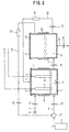
- FIG. 3 shows the third embodiment of the present invention, in which the electrolytic vessel 1 and the storage tank 19 are formed in a pressure-resisting structure which can be hermetically closed. Carbon dioxide is introduced into the electrolytic vessel 1 independently or at the same time. The carbon dioxide thus introduced into the vessel 1 can be formed in a supercritical state.
- the treatment fluid contained in the electrolytic vessel 1 is primarily stored therein, the treatment fluid is separated into air and liquid for reproduction, and the water and carbon dioxide thus reproduced are returned into the electrolytic vessel 1 and the compression pump 15, so that they can be re-utilized.
- the object 3 which is not yet subjected to the degreasing treatment, is received in the electrolytic vessel 1, carbon dioxide is introduced into the electrolytic vessel 1 after the vessel 1 is hermetically closed, and the carbon dioxide is then formed in a supercritical state, i.e., 7.4 MPa and 31 degrees C or higher, through the compression pump 15 and the heater 12, so that the object 3 can be degreased and cleaned.
- a supercritical state i.e., 7.4 MPa and 31 degrees C or higher
- the stop valve 18 is opened to feed the cleaned carbon dioxide into the storage tank 19.
- a predetermined quantity of water 7 and carbon dioxide is introduced into the electrolytic vessel 1 and dissolved to generate a carbonated water.
- a predetermined surface active agent is then added to the carbonated water to form an emulsion state of a supercritical carbon dioxide.
- the dissolving degree of the carbon dioxide with respect to the water 7 can be increased to that extent, and the acid concentration of the carbonated water can be increased.
- the agitator 10 is actuated to agitate the electrolytic solution to generate a large amount of fine air bubble in the electrolytic solution, and a positive current is supplied to the object 3, so that the degreased object 3 is oxidatively reacted with the electrolytic solution to thereby generate an anodic oxide film of amorphous alumina (Al 2 O 3 ) on the base surface of the object 3.
- amorphous alumina Al 2 O 3
- the supply of electric current is stopped and the stop valve 18 is opened to feed the water 7 and the carbon dioxide in an air-liquid two-layer state into the storage tank 19.
- the inventors of the present invention tried to put color on the anodic oxide film thus generated. The result was that the color cannot be put on the anodic oxidation film.
- the reasons for the above can be considered as follows. Since the inside of the electrolytic vessel 1 is held in such a high pressure state as 7.4 MPa at the time of generation of an anodic oxide film, the hole sealing treatment is conducted simultaneously with the generation of the anodic oxide film and the holes formed in the bulk layer of the anodic oxide film are blocked.
- the hole sealing treatment is conducted simultaneously. Accordingly, it is no more required to perform such a troublesome work to form a hole sealing treatment layer and to shift the object 3 to the hole sealing treatment layer, which is conventionally required. Thus, the equipment cost can be reduced, the equipment can be made compact and productivity can be enhanced.
- the present invention is applied to generation of an anodic oxide film.
- the present invention is not limited to this. Instead, the invention can likewise be applied to the electropolishing which is substantially based on the same principle as the anodic oxidation method.
- an anodic oxidation method and a treatment apparatus thereof is capable of generating an oxide film at a low cost and rapidly by eliminating the use of electrolytic solution having a strong acid property and using a carbonated water as the electrolytic solution, capable of improving the oxide film generating operation and rationalizing the water discharging treatment, capable of preventing increase in temperature of the electrolytic solution without a need of a special equipment, capable of generating an oxide film in a stable manner and obtaining a good oxide film by eliminating the generation of oxide in the vicinity of an object to be treated, and capable of rationalization of the oxide film generating treatment and enhancing the productivity by using supercritical carbon dioxide, and suitable, for example, for generation of an oxide film and electropolishing of aluminum.
Landscapes
- Chemical & Material Sciences (AREA)
- Metallurgy (AREA)
- Engineering & Computer Science (AREA)
- Chemical Kinetics & Catalysis (AREA)
- Electrochemistry (AREA)
- Materials Engineering (AREA)
- Organic Chemistry (AREA)
- Inorganic Chemistry (AREA)
- Electrolytic Production Of Non-Metals, Compounds, Apparatuses Therefor (AREA)
- Water Treatment By Electricity Or Magnetism (AREA)
- Processing Of Meat And Fish (AREA)
- Formation Of Insulating Films (AREA)
- Cleaning And De-Greasing Of Metallic Materials By Chemical Methods (AREA)
Abstract
Description
Claims (11)
- An anodic oxidation method for electrolyzing an object to be treated in an electrolytic solution as an anode and generating an oxide film on a surface of said object, wherein said method comprising dissolving a pressurized carbon dioxide in a predetermined quantity of water and generating an oxide film serving a carbonated water of a predetermined acid concentration as an electrolytic solution.
- An anodic oxidation method according to claim 1, wherein air bubbles of said carbonated water are contacted with oxygen in the vicinity of said object so as to move said oxygen.
- An anodic oxidation method according to claim 1, wherein heat of the electrolytic solution is released to the outside by means of air bubbles of the carbonated water.
- An anodic oxidation method according to claim 2 or 3, wherein the carbonated water is agitated to normally generate air bubbles.
- An anodic oxidation method according to claim 2 or 3, wherein degreasing treatment and oxygen film generating treatment are carried out one after another or at the same time with respect to said object.
- An anodic oxidation method according to claim 1, wherein said oxide film is generated in a hermetically closed and pressurized space.
- An anodic oxidation method according to claim 6, wherein generation of said oxide film and hole sealing treatment of said film are carried out simultaneously.
- An anodic oxidation method according to claim 6, wherein supercritical carbon dioxide is dissolved in water and an oxide film is generated using a carbonated water of a predetermined acid concentration as electrolytic solution.
- An anodic oxidation method according to claim 1, wherein after generation of an anodic oxide film, said electrolytic solution is reduced in pressure and discharged.
- An anodic oxidation method according to claim 1, wherein after generation of an anodic oxide film, said electrolytic solution is reduced in pressure and heated to be separated into water and carbon dioxide so as to be discharged or reutilized.
- An anodic oxidation treatment apparatus in which an object to be treated is placed in electrolytic solution received in an electrolytic vessel, and said object is electrolyzed as an anode to generate an oxide film on a surface of said object, wherein water and a pressurized carbon dioxide are introduced into said electrolytic vessel, a pressurized carbon dioxide is dissolved in said water to generate a carbonated water of a predetermined acid concentration, and an oxide film is generated using said carbonated water as an electrolytic solution.
Applications Claiming Priority (3)
| Application Number | Priority Date | Filing Date | Title |
|---|---|---|---|
| JP2001387780A JP3830386B2 (en) | 2001-12-20 | 2001-12-20 | Anodizing method and processing equipment therefor |
| JP2001387780 | 2001-12-20 | ||
| PCT/JP2002/012889 WO2003054253A1 (en) | 2001-12-20 | 2002-12-10 | Anodization method and treating device therefor |
Publications (3)
| Publication Number | Publication Date |
|---|---|
| EP1457588A1 true EP1457588A1 (en) | 2004-09-15 |
| EP1457588A4 EP1457588A4 (en) | 2007-03-07 |
| EP1457588B1 EP1457588B1 (en) | 2012-02-01 |
Family
ID=19188091
Family Applications (1)
| Application Number | Title | Priority Date | Filing Date |
|---|---|---|---|
| EP02783813A Expired - Lifetime EP1457588B1 (en) | 2001-12-20 | 2002-12-10 | Anodization method and treating device therefor |
Country Status (7)
| Country | Link |
|---|---|
| US (1) | US7037420B2 (en) |
| EP (1) | EP1457588B1 (en) |
| JP (1) | JP3830386B2 (en) |
| AT (1) | ATE543928T1 (en) |
| ES (1) | ES2381779T3 (en) |
| TW (1) | TW555891B (en) |
| WO (1) | WO2003054253A1 (en) |
Cited By (4)
| Publication number | Priority date | Publication date | Assignee | Title |
|---|---|---|---|---|
| WO2004101864A1 (en) | 2003-05-16 | 2004-11-25 | Hideo Yoshida | Anodic oxidation method and production method for titanium oxide coating and method of supporting catalyst |
| WO2014104981A1 (en) * | 2012-12-31 | 2014-07-03 | Agency For Science, Technology And Research | Self-assembled ultrashort peptides hydrogels for wound healing, skin care and cosmetics applications |
| CN104032348A (en) * | 2014-06-04 | 2014-09-10 | 张家港市金邦铝业有限公司 | An anodic oxidation tank and brightening technology of strip-series aluminum alloy section bars |
| CN109592700A (en) * | 2018-12-18 | 2019-04-09 | 广西华银铝业有限公司 | A kind of method of alumina producer decomposing grading production continuous operation |
Families Citing this family (13)
| Publication number | Priority date | Publication date | Assignee | Title |
|---|---|---|---|---|
| JP3949504B2 (en) * | 2002-04-25 | 2007-07-25 | 英夫 吉田 | Method and apparatus for activation treatment of base material surface |
| JP4557570B2 (en) * | 2004-03-01 | 2010-10-06 | 成之 上宮 | Method for producing thin film for hydrogen separation |
| DE102004036082A1 (en) * | 2004-07-24 | 2006-02-09 | Km Europa Metal Ag | Method for producing an inorganic covering layer on the surface of a product and panel or band-shaped product |
| JP5002207B2 (en) * | 2006-07-26 | 2012-08-15 | キヤノン株式会社 | Method for manufacturing structure having pattern |
| RU2332528C1 (en) * | 2006-12-15 | 2008-08-27 | Государственное образовательное учреждение высшего профессионального образования Московский государственный институт электронной техники (технический университет) | Electrochemical cell for obtaining porous anode metal oxides and semi-conductors |
| TW200909986A (en) * | 2007-08-31 | 2009-03-01 | Coretronic Corp | Lamp holder and fabrications thereof |
| JP5169401B2 (en) * | 2008-04-07 | 2013-03-27 | 株式会社リコー | Electrophotographic photosensitive member manufacturing method, electrophotographic photosensitive member, image forming apparatus, and process cartridge |
| KR101600428B1 (en) | 2014-07-15 | 2016-03-07 | 한국화학연구원 | Niobium etching methods of heavy ion cavity |
| RU2595167C1 (en) * | 2015-01-12 | 2016-08-20 | Федеральное государственное бюджетное образовательное учреждение высшего образования "Тюменский индустриальный университет" (ТИУ) | Method for anodic treatment of aluminium and its alloys |
| JP6720541B2 (en) * | 2016-01-14 | 2020-07-08 | 日本軽金属株式会社 | Method and device for manufacturing electrode for aluminum electrolytic capacitor |
| CN110908262A (en) * | 2019-12-02 | 2020-03-24 | 中山市仁凯金属制品有限公司 | Heating roller of copying machine and processing method thereof |
| CN111101181A (en) * | 2019-12-20 | 2020-05-05 | 天津大学 | Porous anodic aluminum oxide cooling material, preparation method and application of porous anodic aluminum oxide cooling material in solar cell panel cooling |
| KR102809126B1 (en) * | 2023-12-29 | 2025-05-20 | (주)링크솔루션 | A ceramic lamination apparatus using anodizing method |
Family Cites Families (9)
| Publication number | Priority date | Publication date | Assignee | Title |
|---|---|---|---|---|
| JPS49134A (en) * | 1972-04-20 | 1974-01-05 | ||
| US4111762A (en) * | 1975-01-31 | 1978-09-05 | Martin Marietta Corporation | Optically black coating and process for forming it |
| GB1557281A (en) * | 1976-10-21 | 1979-12-05 | Martin Marietta Corp | Manufacture of low reflectance surfaces involving anodising |
| JPS54115645A (en) * | 1978-02-28 | 1979-09-08 | Ngk Insulators Ltd | Electrochemical treatment |
| US4589972A (en) * | 1984-07-30 | 1986-05-20 | Martin Marietta Corporation | Optically black coating with improved infrared absorption and process of formation |
| JPS6369999A (en) * | 1986-09-11 | 1988-03-30 | Mitsubishi Electric Corp | Stirrer for treating liquid |
| JPH0841686A (en) * | 1994-07-27 | 1996-02-13 | Furukawa Electric Co Ltd:The | How to form patina |
| JPH09176892A (en) | 1995-12-20 | 1997-07-08 | Ricoh Co Ltd | Anodizing method and equipment |
| WO2002016673A1 (en) * | 2000-08-24 | 2002-02-28 | Hideo Yoshida | Electrochemical treating method such as electroplating and electrochemical reaction device therefor |
-
2001
- 2001-12-20 JP JP2001387780A patent/JP3830386B2/en not_active Expired - Fee Related
-
2002
- 2002-05-24 US US10/466,983 patent/US7037420B2/en not_active Expired - Fee Related
- 2002-12-10 AT AT02783813T patent/ATE543928T1/en active
- 2002-12-10 ES ES02783813T patent/ES2381779T3/en not_active Expired - Lifetime
- 2002-12-10 WO PCT/JP2002/012889 patent/WO2003054253A1/en not_active Ceased
- 2002-12-10 EP EP02783813A patent/EP1457588B1/en not_active Expired - Lifetime
- 2002-12-19 TW TW091136697A patent/TW555891B/en not_active IP Right Cessation
Cited By (7)
| Publication number | Priority date | Publication date | Assignee | Title |
|---|---|---|---|---|
| WO2004101864A1 (en) | 2003-05-16 | 2004-11-25 | Hideo Yoshida | Anodic oxidation method and production method for titanium oxide coating and method of supporting catalyst |
| US8475643B2 (en) * | 2003-05-16 | 2013-07-02 | Hideo Yoshida | Anodic oxidation method and production for titanium oxide coating and method of supporting catalyst |
| WO2014104981A1 (en) * | 2012-12-31 | 2014-07-03 | Agency For Science, Technology And Research | Self-assembled ultrashort peptides hydrogels for wound healing, skin care and cosmetics applications |
| CN105189532A (en) * | 2012-12-31 | 2015-12-23 | 新加坡科技研究局 | Self-assembled ultrashort peptides hydrogels for wound healing, skin care and cosmetics applications |
| CN105189532B (en) * | 2012-12-31 | 2020-11-03 | 新加坡科技研究局 | Self-assembled ultrashort peptide hydrogels for wound healing, skin care and cosmetic applications |
| CN104032348A (en) * | 2014-06-04 | 2014-09-10 | 张家港市金邦铝业有限公司 | An anodic oxidation tank and brightening technology of strip-series aluminum alloy section bars |
| CN109592700A (en) * | 2018-12-18 | 2019-04-09 | 广西华银铝业有限公司 | A kind of method of alumina producer decomposing grading production continuous operation |
Also Published As
| Publication number | Publication date |
|---|---|
| JP3830386B2 (en) | 2006-10-04 |
| JP2003183888A (en) | 2003-07-03 |
| US7037420B2 (en) | 2006-05-02 |
| EP1457588A4 (en) | 2007-03-07 |
| TW555891B (en) | 2003-10-01 |
| US20040206632A1 (en) | 2004-10-21 |
| EP1457588B1 (en) | 2012-02-01 |
| ES2381779T3 (en) | 2012-05-31 |
| ATE543928T1 (en) | 2012-02-15 |
| WO2003054253A1 (en) | 2003-07-03 |
| TW200301317A (en) | 2003-07-01 |
Similar Documents
| Publication | Publication Date | Title |
|---|---|---|
| US7037420B2 (en) | Anodic oxidation method and treatment apparatus thereof | |
| US7857952B2 (en) | Method for treating the surface of object and apparatus thereof | |
| US5980722A (en) | Plated aluminum alloy, cylinder block thereof, plating line and plating method | |
| US5750014A (en) | Apparatus for selectively coating metal parts | |
| US20030019756A1 (en) | Electrochemical treating method such as electroplating and electrochemical reaction device therefor | |
| JP2002519179A (en) | Immersion processing method and apparatus for semiconductors and other equipment | |
| US8475643B2 (en) | Anodic oxidation method and production for titanium oxide coating and method of supporting catalyst | |
| US5104496A (en) | Low mist chromium plating method and system | |
| US5534126A (en) | Apparatus and method for selective coating of metal parts | |
| JP3703132B2 (en) | Electrochemical treatment method such as electroplating and electrochemical reaction apparatus thereof | |
| JP2003147591A (en) | Method and apparatus for treating surface of object to be treated | |
| JP2662163B2 (en) | Electrolytic cell | |
| JP4308576B2 (en) | Anodizing method | |
| KR102661735B1 (en) | Compartmental tank | |
| KR20180087414A (en) | High durability plated body | |
| US20080251103A1 (en) | Method for activating surface of base material and apparatus thereof | |
| JP4445767B2 (en) | Method and apparatus for producing rust-proof functional water | |
| JP2003073868A (en) | Method for activating surface of base material and apparatus therefor | |
| US5411652A (en) | Optimum conversion chamber | |
| EP0060091A2 (en) | Apparatus and method for electrolytically treating an ion containing liquid such as chromium plating rinse water | |
| JPS59162987A (en) | Etching processing equipment |
Legal Events
| Date | Code | Title | Description |
|---|---|---|---|
| PUAI | Public reference made under article 153(3) epc to a published international application that has entered the european phase |
Free format text: ORIGINAL CODE: 0009012 |
|
| 17P | Request for examination filed |
Effective date: 20030712 |
|
| AK | Designated contracting states |
Kind code of ref document: A1 Designated state(s): AT BE BG CH CY CZ DE DK EE ES FI FR GB GR IE IT LI LU MC NL PT SE SI SK TR |
|
| A4 | Supplementary search report drawn up and despatched |
Effective date: 20070206 |
|
| RIC1 | Information provided on ipc code assigned before grant |
Ipc: C25D 11/02 20060101AFI20070131BHEP Ipc: C25D 11/08 20060101ALI20070131BHEP |
|
| 17Q | First examination report despatched |
Effective date: 20080516 |
|
| GRAP | Despatch of communication of intention to grant a patent |
Free format text: ORIGINAL CODE: EPIDOSNIGR1 |
|
| GRAS | Grant fee paid |
Free format text: ORIGINAL CODE: EPIDOSNIGR3 |
|
| GRAA | (expected) grant |
Free format text: ORIGINAL CODE: 0009210 |
|
| AK | Designated contracting states |
Kind code of ref document: B1 Designated state(s): AT BE BG CH CY CZ DE DK EE ES FI FR GB GR IE IT LI LU MC NL PT SE SI SK TR |
|
| REG | Reference to a national code |
Ref country code: GB Ref legal event code: FG4D |
|
| REG | Reference to a national code |
Ref country code: CH Ref legal event code: EP Ref country code: AT Ref legal event code: REF Ref document number: 543928 Country of ref document: AT Kind code of ref document: T Effective date: 20120215 |
|
| REG | Reference to a national code |
Ref country code: DE Ref legal event code: R096 Ref document number: 60242150 Country of ref document: DE Effective date: 20120329 |
|
| REG | Reference to a national code |
Ref country code: CH Ref legal event code: NV Representative=s name: CABINET ROLAND NITHARDT CONSEILS EN PROPRIETE INDU Ref country code: SE Ref legal event code: TRGR |
|
| REG | Reference to a national code |
Ref country code: NL Ref legal event code: VDEP Effective date: 20120201 |
|
| REG | Reference to a national code |
Ref country code: ES Ref legal event code: FG2A Ref document number: 2381779 Country of ref document: ES Kind code of ref document: T3 Effective date: 20120531 |
|
| PG25 | Lapsed in a contracting state [announced via postgrant information from national office to epo] |
Ref country code: NL Free format text: LAPSE BECAUSE OF FAILURE TO SUBMIT A TRANSLATION OF THE DESCRIPTION OR TO PAY THE FEE WITHIN THE PRESCRIBED TIME-LIMIT Effective date: 20120201 |
|
| PG25 | Lapsed in a contracting state [announced via postgrant information from national office to epo] |
Ref country code: FI Free format text: LAPSE BECAUSE OF FAILURE TO SUBMIT A TRANSLATION OF THE DESCRIPTION OR TO PAY THE FEE WITHIN THE PRESCRIBED TIME-LIMIT Effective date: 20120201 Ref country code: GR Free format text: LAPSE BECAUSE OF FAILURE TO SUBMIT A TRANSLATION OF THE DESCRIPTION OR TO PAY THE FEE WITHIN THE PRESCRIBED TIME-LIMIT Effective date: 20120502 Ref country code: BE Free format text: LAPSE BECAUSE OF FAILURE TO SUBMIT A TRANSLATION OF THE DESCRIPTION OR TO PAY THE FEE WITHIN THE PRESCRIBED TIME-LIMIT Effective date: 20120201 Ref country code: PT Free format text: LAPSE BECAUSE OF FAILURE TO SUBMIT A TRANSLATION OF THE DESCRIPTION OR TO PAY THE FEE WITHIN THE PRESCRIBED TIME-LIMIT Effective date: 20120601 |
|
| REG | Reference to a national code |
Ref country code: AT Ref legal event code: MK05 Ref document number: 543928 Country of ref document: AT Kind code of ref document: T Effective date: 20120201 |
|
| PG25 | Lapsed in a contracting state [announced via postgrant information from national office to epo] |
Ref country code: CY Free format text: LAPSE BECAUSE OF FAILURE TO SUBMIT A TRANSLATION OF THE DESCRIPTION OR TO PAY THE FEE WITHIN THE PRESCRIBED TIME-LIMIT Effective date: 20120201 |
|
| PG25 | Lapsed in a contracting state [announced via postgrant information from national office to epo] |
Ref country code: EE Free format text: LAPSE BECAUSE OF FAILURE TO SUBMIT A TRANSLATION OF THE DESCRIPTION OR TO PAY THE FEE WITHIN THE PRESCRIBED TIME-LIMIT Effective date: 20120201 Ref country code: CZ Free format text: LAPSE BECAUSE OF FAILURE TO SUBMIT A TRANSLATION OF THE DESCRIPTION OR TO PAY THE FEE WITHIN THE PRESCRIBED TIME-LIMIT Effective date: 20120201 Ref country code: SI Free format text: LAPSE BECAUSE OF FAILURE TO SUBMIT A TRANSLATION OF THE DESCRIPTION OR TO PAY THE FEE WITHIN THE PRESCRIBED TIME-LIMIT Effective date: 20120201 Ref country code: DK Free format text: LAPSE BECAUSE OF FAILURE TO SUBMIT A TRANSLATION OF THE DESCRIPTION OR TO PAY THE FEE WITHIN THE PRESCRIBED TIME-LIMIT Effective date: 20120201 |
|
| PG25 | Lapsed in a contracting state [announced via postgrant information from national office to epo] |
Ref country code: SK Free format text: LAPSE BECAUSE OF FAILURE TO SUBMIT A TRANSLATION OF THE DESCRIPTION OR TO PAY THE FEE WITHIN THE PRESCRIBED TIME-LIMIT Effective date: 20120201 |
|
| PLBE | No opposition filed within time limit |
Free format text: ORIGINAL CODE: 0009261 |
|
| STAA | Information on the status of an ep patent application or granted ep patent |
Free format text: STATUS: NO OPPOSITION FILED WITHIN TIME LIMIT |
|
| 26N | No opposition filed |
Effective date: 20121105 |
|
| PG25 | Lapsed in a contracting state [announced via postgrant information from national office to epo] |
Ref country code: AT Free format text: LAPSE BECAUSE OF FAILURE TO SUBMIT A TRANSLATION OF THE DESCRIPTION OR TO PAY THE FEE WITHIN THE PRESCRIBED TIME-LIMIT Effective date: 20120201 |
|
| PGFP | Annual fee paid to national office [announced via postgrant information from national office to epo] |
Ref country code: GB Payment date: 20121231 Year of fee payment: 11 Ref country code: SE Payment date: 20121203 Year of fee payment: 11 Ref country code: IT Payment date: 20121129 Year of fee payment: 11 Ref country code: ES Payment date: 20121218 Year of fee payment: 11 |
|
| REG | Reference to a national code |
Ref country code: DE Ref legal event code: R097 Ref document number: 60242150 Country of ref document: DE Effective date: 20121105 |
|
| PGFP | Annual fee paid to national office [announced via postgrant information from national office to epo] |
Ref country code: DE Payment date: 20121220 Year of fee payment: 11 Ref country code: FR Payment date: 20130131 Year of fee payment: 11 Ref country code: CH Payment date: 20130321 Year of fee payment: 11 |
|
| PG25 | Lapsed in a contracting state [announced via postgrant information from national office to epo] |
Ref country code: MC Free format text: LAPSE BECAUSE OF NON-PAYMENT OF DUE FEES Effective date: 20121231 Ref country code: BG Free format text: LAPSE BECAUSE OF FAILURE TO SUBMIT A TRANSLATION OF THE DESCRIPTION OR TO PAY THE FEE WITHIN THE PRESCRIBED TIME-LIMIT Effective date: 20120501 |
|
| REG | Reference to a national code |
Ref country code: IE Ref legal event code: MM4A |
|
| PG25 | Lapsed in a contracting state [announced via postgrant information from national office to epo] |
Ref country code: IE Free format text: LAPSE BECAUSE OF NON-PAYMENT OF DUE FEES Effective date: 20121210 |
|
| PG25 | Lapsed in a contracting state [announced via postgrant information from national office to epo] |
Ref country code: TR Free format text: LAPSE BECAUSE OF FAILURE TO SUBMIT A TRANSLATION OF THE DESCRIPTION OR TO PAY THE FEE WITHIN THE PRESCRIBED TIME-LIMIT Effective date: 20120201 |
|
| PG25 | Lapsed in a contracting state [announced via postgrant information from national office to epo] |
Ref country code: LU Free format text: LAPSE BECAUSE OF NON-PAYMENT OF DUE FEES Effective date: 20121210 |
|
| REG | Reference to a national code |
Ref country code: DE Ref legal event code: R119 Ref document number: 60242150 Country of ref document: DE |
|
| REG | Reference to a national code |
Ref country code: SE Ref legal event code: EUG |
|
| REG | Reference to a national code |
Ref country code: CH Ref legal event code: PL |
|
| GBPC | Gb: european patent ceased through non-payment of renewal fee |
Effective date: 20131210 |
|
| PG25 | Lapsed in a contracting state [announced via postgrant information from national office to epo] |
Ref country code: SE Free format text: LAPSE BECAUSE OF NON-PAYMENT OF DUE FEES Effective date: 20131211 |
|
| REG | Reference to a national code |
Ref country code: FR Ref legal event code: ST Effective date: 20140829 |
|
| REG | Reference to a national code |
Ref country code: DE Ref legal event code: R119 Ref document number: 60242150 Country of ref document: DE Effective date: 20140701 |
|
| PG25 | Lapsed in a contracting state [announced via postgrant information from national office to epo] |
Ref country code: LI Free format text: LAPSE BECAUSE OF NON-PAYMENT OF DUE FEES Effective date: 20131231 Ref country code: CH Free format text: LAPSE BECAUSE OF NON-PAYMENT OF DUE FEES Effective date: 20131231 Ref country code: DE Free format text: LAPSE BECAUSE OF NON-PAYMENT OF DUE FEES Effective date: 20140701 |
|
| PG25 | Lapsed in a contracting state [announced via postgrant information from national office to epo] |
Ref country code: GB Free format text: LAPSE BECAUSE OF NON-PAYMENT OF DUE FEES Effective date: 20131210 Ref country code: FR Free format text: LAPSE BECAUSE OF NON-PAYMENT OF DUE FEES Effective date: 20131231 |
|
| REG | Reference to a national code |
Ref country code: ES Ref legal event code: FD2A Effective date: 20150330 |
|
| PG25 | Lapsed in a contracting state [announced via postgrant information from national office to epo] |
Ref country code: ES Free format text: LAPSE BECAUSE OF NON-PAYMENT OF DUE FEES Effective date: 20131211 |
|
| PG25 | Lapsed in a contracting state [announced via postgrant information from national office to epo] |
Ref country code: IT Free format text: LAPSE BECAUSE OF NON-PAYMENT OF DUE FEES Effective date: 20131231 |
|
| PG25 | Lapsed in a contracting state [announced via postgrant information from national office to epo] |
Ref country code: IT Free format text: LAPSE BECAUSE OF NON-PAYMENT OF DUE FEES Effective date: 20131210 |