EP1457445A2 - Sheet feeder in image reading apparatus - Google Patents
Sheet feeder in image reading apparatus Download PDFInfo
- Publication number
- EP1457445A2 EP1457445A2 EP04251424A EP04251424A EP1457445A2 EP 1457445 A2 EP1457445 A2 EP 1457445A2 EP 04251424 A EP04251424 A EP 04251424A EP 04251424 A EP04251424 A EP 04251424A EP 1457445 A2 EP1457445 A2 EP 1457445A2
- Authority
- EP
- European Patent Office
- Prior art keywords
- sheet
- segments
- driven roller
- drive shaft
- roller
- Prior art date
- Legal status (The legal status is an assumption and is not a legal conclusion. Google has not performed a legal analysis and makes no representation as to the accuracy of the status listed.)
- Granted
Links
- 238000011144 upstream manufacturing Methods 0.000 claims abstract description 19
- 239000011521 glass Substances 0.000 description 7
- 238000007599 discharging Methods 0.000 description 4
- 238000001514 detection method Methods 0.000 description 3
- 230000002093 peripheral effect Effects 0.000 description 2
- 229930182556 Polyacetal Natural products 0.000 description 1
- 230000005540 biological transmission Effects 0.000 description 1
- 230000003247 decreasing effect Effects 0.000 description 1
- 239000004973 liquid crystal related substance Substances 0.000 description 1
- 229920006324 polyoxymethylene Polymers 0.000 description 1
- 238000000926 separation method Methods 0.000 description 1
- 229920002994 synthetic fiber Polymers 0.000 description 1
Images




Classifications
-
- B—PERFORMING OPERATIONS; TRANSPORTING
- B65—CONVEYING; PACKING; STORING; HANDLING THIN OR FILAMENTARY MATERIAL
- B65H—HANDLING THIN OR FILAMENTARY MATERIAL, e.g. SHEETS, WEBS, CABLES
- B65H29/00—Delivering or advancing articles from machines; Advancing articles to or into piles
- B65H29/12—Delivering or advancing articles from machines; Advancing articles to or into piles by means of the nip between two, or between two sets of, moving tapes or bands or rollers
- B65H29/14—Delivering or advancing articles from machines; Advancing articles to or into piles by means of the nip between two, or between two sets of, moving tapes or bands or rollers and introducing into a pile
-
- B—PERFORMING OPERATIONS; TRANSPORTING
- B65—CONVEYING; PACKING; STORING; HANDLING THIN OR FILAMENTARY MATERIAL
- B65H—HANDLING THIN OR FILAMENTARY MATERIAL, e.g. SHEETS, WEBS, CABLES
- B65H2404/00—Parts for transporting or guiding the handled material
- B65H2404/10—Rollers
- B65H2404/13—Details of longitudinal profile
- B65H2404/133—Limited number of active elements on common axis
-
- B—PERFORMING OPERATIONS; TRANSPORTING
- B65—CONVEYING; PACKING; STORING; HANDLING THIN OR FILAMENTARY MATERIAL
- B65H—HANDLING THIN OR FILAMENTARY MATERIAL, e.g. SHEETS, WEBS, CABLES
- B65H2404/00—Parts for transporting or guiding the handled material
- B65H2404/10—Rollers
- B65H2404/13—Details of longitudinal profile
- B65H2404/134—Axle
-
- B—PERFORMING OPERATIONS; TRANSPORTING
- B65—CONVEYING; PACKING; STORING; HANDLING THIN OR FILAMENTARY MATERIAL
- B65H—HANDLING THIN OR FILAMENTARY MATERIAL, e.g. SHEETS, WEBS, CABLES
- B65H2404/00—Parts for transporting or guiding the handled material
- B65H2404/10—Rollers
- B65H2404/14—Roller pairs
- B65H2404/143—Roller pairs driving roller and idler roller arrangement
- B65H2404/1431—Roller pairs driving roller and idler roller arrangement idler roller details
-
- B—PERFORMING OPERATIONS; TRANSPORTING
- B65—CONVEYING; PACKING; STORING; HANDLING THIN OR FILAMENTARY MATERIAL
- B65H—HANDLING THIN OR FILAMENTARY MATERIAL, e.g. SHEETS, WEBS, CABLES
- B65H2404/00—Parts for transporting or guiding the handled material
- B65H2404/50—Surface of the elements in contact with the forwarded or guided material
- B65H2404/53—Surface of the elements in contact with the forwarded or guided material with particular mechanical, physical properties
- B65H2404/531—Surface of the elements in contact with the forwarded or guided material with particular mechanical, physical properties particular coefficient of friction
-
- B—PERFORMING OPERATIONS; TRANSPORTING
- B65—CONVEYING; PACKING; STORING; HANDLING THIN OR FILAMENTARY MATERIAL
- B65H—HANDLING THIN OR FILAMENTARY MATERIAL, e.g. SHEETS, WEBS, CABLES
- B65H2801/00—Application field
- B65H2801/03—Image reproduction devices
- B65H2801/06—Office-type machines, e.g. photocopiers
Definitions
- the invention relates to a sheet feeder that feeds a sheet, such as a document, in an image reading apparatus, and, more particularly, to a structure to prevent image reading failures caused by a sheet to be fed being instantaneously stopped at a reading part when a leading edge of the sheet collides with a roller disposed at a downstream position of the reading part.
- a sheet feeder which comprises a roller pair, that is, a drive roller and a driven roller used in pair, is provided at a downstream side of the reading part. If axes of the drive roller and the driven roller are set in a direction perpendicular to a sheet feed direction, a nip portion between the drive roller and the driven roller extends in an axial direction of the rollers and is parallel to the direction perpendicular to the sheet feed direction.
- Japanese Laid-Open Patent Publication No. 2001-310857 discloses a paper sheet discharging mechanism formed of pairs of rollers, which are driving rollers and driven rollers, that press against the driving rollers, for discharging the paper sheets from the inside of the device.
- Axes of the driven rollers that press the paper sheets to the driving rollers, that convey the paper sheets in the sheet discharging direction, are disposed on planes parallel to the axes of the driving rollers, and arranged symmetrically with respect to a centerline of the sheets to be discharged and inclined with respect to the axes of the driving rollers.
- the sheets to be discharged are deflected at a center of the width, the deflection continues in the direction of travel, which produces a shape based stiffness in the sheets, thereby making the sheets stiff.
- this prevents the sheets from drooping downstream of the roller feeding, and jamming during discharge.
- the deflection protruding substantially in the center of the document may continue up to the upstream side of the feeding.
- the deflection may be curved approaching or going away from the reading part, resulting in the distance from the document to the reading part may change between a part with the deflection and a part without the deflection.
- the degree of approach of the document to the reading part in its width direction varies greatly. As a result, image data of correct size cannot be obtained.
- the invention provides a sheet feeder in an image reading apparatus, which is capable of obtaining image data correctly.
- a sheet feeder that feeds a sheet in an image reading apparatus with an image reading part may include a drive roller unit that is disposed at a downstream side from the reading part in a sheet feed direction and includes a drive roller, and a driven roller unit that includes a driven roller that presses against the drive roller.
- a coefficient of friction of an outer layer of the driven roller to a sheet to be fed may be smaller than a coefficient of friction of an outer layer of the drive roller to the sheet.
- an axis of the drive roller may be disposed perpendicular to the sheet feed direction, and an axis of the driven roller disposed on a slant with respect to the sheet feed direction.
- FIG. 1 is a perspective view of a multifunction device including a document reader having an auto sheet feeder according to the invention
- FIG. 2 is perspective view where a cover of the document reader having the auto sheet feeder is open from a main body case;
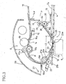
- FIG. 3 is side sectional view showing essential parts of the document reader having the auto sheet feeder
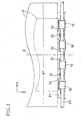
- FIG. 4 is a top view of a pair of ejection rollers disposed on a downstream side from a document reading part with respect to a sheet feed direction;
- FIG. 5A is a top view of driven rollers except for drive rollers
- FIG. 5B is an enlarged perspective view of a guide groove for a support shaft of a driven roller
- FIG. 5C is an enlarged sectional view taken along line V c -V c of FIG. 5A;
- FIG. 6A is a pictorial view showing a first embodiment of the invention.
- FIG. 6B is a view showing another embodiment of the invention.
- FIG. 6C is a view showing a further embodiment of the invention.
- FIG. 1 An exemplary embodiment of the invention will be described in detail with reference to the accompanying drawings.
- the embodiment is applied to a document reader 2 with an auto sheet feeder 6 in a multifunction device 1 including a facsimile function, a scanner function, a copier function, and a printer function.
- a large-sized glass plate 4 for placing a document thereon is fixed in a horizontal state on a top surface of a main body case 3 of the multifunction device 1.
- An operation panel portion 5 is provided in a front part of the top surface of the main body case 3.
- the operation panel portion 5 includes a ten keypad for executing the facsimile function, the scanner function, and the copier function, buttons for issuing directives for various operations, and a liquid crystal display.
- the document reader 2 As shown in FIGS. 1 and 2, the document reader 2, with the auto sheet feeder 6, is made up of a cover assembly 7, the auto sheet feeder 6, and a reading element 9.
- the cover assembly 7 is attached to a rear edge of the top surface of the main body case 3 via hinges 8 so as to swing up and down.
- the auto sheet feeder 6 is provided on one end of a top surface of the cover assembly 7, and the reading element 9 includes a line-type CCD image pickup device, which is arranged at one end of a lower surface of a side-edge 4a of the glass plate 4.
- the glass plate 4 is fixed to the upper surface of the main body case 3.
- the document reader 2 is structured such that a document is placed face down on the large-sized glass plate 4 and is held by a holding member 7a.
- the holding member 7a is, for example, a sponge pad provided on a lower surface of the cover assembly 7. Images on the document are read by the reading element 9 that moves on a guide rail 10 disposed along the lower surface of the large-sized glass plate 4 on the basis of an image reading instruction.
- a case portion 11 of the auto sheet feeder 6 is fixed on one end of the cover assembly 7, and a document tray 12 is disposed on one end of the case portion 11 at an inclined angle so that its free end extends upwardly.
- a discharge paper tray 13 is formed on the top surface of the cover assembly 7 where a document P is discharged.
- a beginning 14a of the upper path plate 14 is located in close proximity to the document tray 12.
- a separation roller 15 that feeds documents P, while separating them one by one, stacked on the document tray 12, a sheet sensor 16, with a detection lever 16a that pivots by contact with a leading edge of the document P, and a pair of paper feed rollers 17a, 17b are provided on the upper path plate 14.
- a downward curved end 14b of the upper path plate 14 and a beginning 18a of a lower path plate 18 partially overlap.
- An end 18b of the lower path plate 18 extends toward ejection rollers 19, 20 arranged proximate the discharge paper tray 13.
- a pair of conveying rollers 21a, 21b are disposed close to the beginning 18a of the lower path plate 18 at an upstream side of a reading point 23a.
- a rear sensor 22, with a detection lever 22a is provided in close proximity to the conveying rollers 21 a, 21 b.
- the detection lever 22a detects the leading and trailing edges of a document P to find its length and to determine the occurrence of a paper jam.
- the lower path plate 18 is curved downwardly in the middle portion with respect to a feed direction, and includes a reading window 23 at its lowest position.
- the reading window 23 has a rectangular shape, in plan view, and opens above the reading device 9 when at the stop position.
- the reading window 23 is formed such that a length Lo, in the sheet feed direction, is short and a length in a direction perpendicular to the sheet feed direction is long (with reference to FIGS. 1 and 3).
- a plurality of ribs 24 are arranged above the lower path plate 18 with such a narrow spacing that a document P can pass so that a lower surface (from which the image is read) of the document P can slide on a surface of the reading point 23a.
- a cover 26 is pivotable about a shaft 27 at its proximal end on one end of the case portion 11 (opposite from the document tray 12), and is structured so as to expose the upper portion of the upper path plate 14 when a paper jam occurs.
- the drive roller 19 and the driven roller 20 are disposed at a downstream side from the reading point 23a. Both the drive roller 19 and the driven roller 20 comprise a plurality of roller segments.
- the drive roller 19, disposed on an upper side, is fixed to a drive shaft 29 that is parallel to a direction perpendicular to the sheet feed direction (X-axis direction in FIG. 4).
- the drive shaft 29 is rotated by a drive motor and a transmission gear (not shown) in sheet feed direction.
- At least a peripheral layer of the drive roller 19 is made from rubber having a large coefficient of friction with respect to the document P. Pairs of segments of the drive roller 19 and the driven roller 20 are provided in a plurality of places on drive shaft 29 and support shafts 30, respectively (four places, or pairs in the embodiment), and symmetrically on each side of a centerline O of the document P with respect to its width (a sheet dimension in Y-axis direction in FIG. 4).
- each segment of the driven roller 20 is made from a synthetic material, such as polyacetal, having a lower coefficient of friction with respect to the document P than that of the segments of the drive roller 19.
- the driven roller 20 preferably has a minimal coefficient of friction. That is, the driven roller 20 must have a coefficient of friction lower than, at least, that of the drive roller 19.
- the segments of the driven roller 20 are fitted on a pair of support shafts 30 so as to press against the corresponding segments of drive roller 19.
- the segments of the driven roller 20 are arranged symmetrically with two segments on each side of the centerline O and axes 20a of the driven roller 20 segments (axes of the support shafts 30) are arranged so they are not perpendicular to the sheet feed direction (X-axis direction), i.e., not parallel to the Y-axis direction, but are inclined at an angle of ⁇ degrees (1 to 3 degrees in the embodiment, for example and exaggerated in Figure 5A for purposes of illustration) with respect to the Y-axis.
- the driven roller 20 segments are disposed on a slant such that the driven roller 20 segments close to the centerline O are on the downstream side of the sheet feed direction and the driven roller 20 segments far from the centerline O are on the upstream side (refer to FIG. 5A).
- the support shafts 30 are supported in guide grooves 31, which are open upwardly in the case portion 11, so as to be movable vertically (FIG. 5B).
- the support shafts 30 are urged by urging members 33, such as coil springs, plate springs, and elastic members made from rubber, mounted in recessed receiving portions 32 formed adjacent each of the guide grooves 31 so that the driven roller 20 segments are pressed against the drive roller 19 segments (FIG. 5C).
- the guide grooves 31 that support the respective support shafts 30 are formed as pairs and at positions out of alignment such that the inner guide grooves 31 (disposed on a side close to the centerline O) are, with respect to the drive shaft 29, on the downstream side of the sheet feed direction and outer guide grooves 31 (disposed distant from the centerline O) are, with respect to the drive shaft 29, on the upstream side of the sheet feed direction.
- the support shafts 30 are inclined at the angle of ⁇ degrees.
- a leading edge P1 of the document P which is conveyed from the upstream side of the sheet feed direction, first collides against nip portions N1, N1 between the drive roller 19 segments and the driven roller 20 segments.
- the nip portions N1, N1 are closest to the upstream side in the sheet feed direction (FIG. 6A), of the driven roller 20 segments which are arranged on a slant, and contact the leading edge P1 of the document P substantially at points, so that impact is minute.
- the driven roller 20 segments are arranged symmetrically on both sides of the centerline O, and the axes 20a are arranged on a slant such that the driven roller 20 segments close to the centerline O are on the upstream side of the sheet feed direction and the driven roller 20 segments far from the centerline O are on the downstream side of the sheet feed direction.
- the driven roller 20 segments close to each side of the centerline O are the only segments disposed on a slant so as to be located on the upstream side of the sheet feed direction.
- the axes 20a of the driven roller 20 segments far from the centerline O are disposed perpendicularly to the sheet feed direction (the X-axis direction), that is parallel to the Y-axis direction.
- FIGS. 6B and 6C have the advantage that the leading edge P1 of the document P can be reliably held at the paired nip portions N1 and are of point-contact type even when a width W1 of the document P is small, rather than the larger width shown in FIG. 6A.
- the drive roller 19 segments may be combined into one or two roller segments that are continuously long in the Y-axis direction, and the plurality of segments of the driven roller 20 may be arranged to press the one or two rollers at intervals.
- the urging members 33 may be provided for each segment of the driven roller 20 to urge the segments individually.
- the axis 20a of one segment of the driven roller 20 only may be disposed on a slant toward the upstream or downstream side of the sheet feed direction in keeping with the concept of the embodiment.
- the urging members 33 that urge the driven roller 20 segments into contact with the drive roller 19, are provided on each axis 20a disposed symmetrically with respect to the center of the width of the document, the number of locations of the urging members 33 is decreased and, thus, costs can be reduced.
- the direction of the sheet (the document P) may be changed in a path from the reading point 23a to just before the nip portion between the ejection rollers 19, 20 such that the sheet can be substantially parallel to the glass plate 4, and then the leading edge P1 may be inserted into the nip portion.
- the impact at the nip portion can be reduced, thereby preventing the document P, being fed, from deflecting at the reading point 23a.
- the invention may be applied to not only an auto sheet feeder but also to a sheet ejection part located on a downstream side from a device that feeds sheets (documents P) one by one and executes reading while conveying.
Landscapes
- Engineering & Computer Science (AREA)
- Mechanical Engineering (AREA)
- Delivering By Means Of Belts And Rollers (AREA)
- Facsimiles In General (AREA)
- Separation, Sorting, Adjustment, Or Bending Of Sheets To Be Conveyed (AREA)
Abstract
Description
- This application claims priority from JP 2003-070679, filed March 14, 2003, the disclosure of which is incorporated in its entirety herein by reference thereto.
- The invention relates to a sheet feeder that feeds a sheet, such as a document, in an image reading apparatus, and, more particularly, to a structure to prevent image reading failures caused by a sheet to be fed being instantaneously stopped at a reading part when a leading edge of the sheet collides with a roller disposed at a downstream position of the reading part.
- Conventionally, in a facsimile, scanner or copier, a plurality of documents are stacked at one place, and fed one by one by an auto sheet feeder to read images on the documents at a reading part where a line-type CCD image pickup device or a line-type contact image sensor (CIS) is disposed. In this case, a sheet feeder, which comprises a roller pair, that is, a drive roller and a driven roller used in pair, is provided at a downstream side of the reading part. If axes of the drive roller and the driven roller are set in a direction perpendicular to a sheet feed direction, a nip portion between the drive roller and the driven roller extends in an axial direction of the rollers and is parallel to the direction perpendicular to the sheet feed direction. Thus, at the instant when the leading edge of the sheet collides against the nip portion along the length of the nip portion and width of the sheet, a load at the collision is great, and the feeding of the sheet is instantaneously stopped, resulting in a problem that the movement of images being read on the sheet is disrupted at the reading part and image data can not be accurately obtained.
- On the other hand, when a sheet to be passed through a paper sheet discharging mechanism is not stiff (rigidity is not sufficient), as a structure to reinforce the stiffness, Japanese Laid-Open Patent Publication No. 2001-310857 (FIGS. 1 to 5) discloses a paper sheet discharging mechanism formed of pairs of rollers, which are driving rollers and driven rollers, that press against the driving rollers, for discharging the paper sheets from the inside of the device. Axes of the driven rollers that press the paper sheets to the driving rollers, that convey the paper sheets in the sheet discharging direction, are disposed on planes parallel to the axes of the driving rollers, and arranged symmetrically with respect to a centerline of the sheets to be discharged and inclined with respect to the axes of the driving rollers.
- According to this structure, the sheets to be discharged are deflected at a center of the width, the deflection continues in the direction of travel, which produces a shape based stiffness in the sheets, thereby making the sheets stiff. Thus, this prevents the sheets from drooping downstream of the roller feeding, and jamming during discharge.
- However, if the sheet feeder, made up of the pairs of the rollers with the structure disclosed in the former publication, is provided at the downstream side of the reading part, the deflection protruding substantially in the center of the document may continue up to the upstream side of the feeding. Thus, the deflection may be curved approaching or going away from the reading part, resulting in the distance from the document to the reading part may change between a part with the deflection and a part without the deflection. Thus, the degree of approach of the document to the reading part in its width direction varies greatly. As a result, image data of correct size cannot be obtained.
- The invention provides a sheet feeder in an image reading apparatus, which is capable of obtaining image data correctly.
- According to exemplary embodiments of the invention, a sheet feeder that feeds a sheet in an image reading apparatus with an image reading part may include a drive roller unit that is disposed at a downstream side from the reading part in a sheet feed direction and includes a drive roller, and a driven roller unit that includes a driven roller that presses against the drive roller. A coefficient of friction of an outer layer of the driven roller to a sheet to be fed may be smaller than a coefficient of friction of an outer layer of the drive roller to the sheet. Further, an axis of the drive roller may be disposed perpendicular to the sheet feed direction, and an axis of the driven roller disposed on a slant with respect to the sheet feed direction.
- An embodiment of the invention will be described in detail with reference to the following figures, wherein:
- FIG. 1 is a perspective view of a multifunction device including a document reader having an auto sheet feeder according to the invention;
- FIG. 2 is perspective view where a cover of the document reader having the auto sheet feeder is open from a main body case;
- FIG. 3 is side sectional view showing essential parts of the document reader having the auto sheet feeder;
- FIG. 4 is a top view of a pair of ejection rollers disposed on a downstream side from a document reading part with respect to a sheet feed direction;
- FIG. 5A is a top view of driven rollers except for drive rollers;
- FIG. 5B is an enlarged perspective view of a guide groove for a support shaft of a driven roller;
- FIG. 5C is an enlarged sectional view taken along line Vc-Vc of FIG. 5A;
- FIG. 6A is a pictorial view showing a first embodiment of the invention;
- FIG. 6B is a view showing another embodiment of the invention; and
- FIG. 6C is a view showing a further embodiment of the invention.
- An exemplary embodiment of the invention will be described in detail with reference to the accompanying drawings. As shown in FIG. 1, the embodiment is applied to a
document reader 2 with anauto sheet feeder 6 in a multifunction device 1 including a facsimile function, a scanner function, a copier function, and a printer function. - A large-
sized glass plate 4 for placing a document thereon is fixed in a horizontal state on a top surface of amain body case 3 of the multifunction device 1. Anoperation panel portion 5 is provided in a front part of the top surface of themain body case 3. Theoperation panel portion 5 includes a ten keypad for executing the facsimile function, the scanner function, and the copier function, buttons for issuing directives for various operations, and a liquid crystal display. - As shown in FIGS. 1 and 2, the
document reader 2, with theauto sheet feeder 6, is made up of acover assembly 7, theauto sheet feeder 6, and areading element 9. Thecover assembly 7 is attached to a rear edge of the top surface of themain body case 3 via hinges 8 so as to swing up and down. Theauto sheet feeder 6 is provided on one end of a top surface of thecover assembly 7, and thereading element 9 includes a line-type CCD image pickup device, which is arranged at one end of a lower surface of a side-edge 4a of theglass plate 4. Theglass plate 4 is fixed to the upper surface of themain body case 3. In the embodiment, thedocument reader 2 is structured such that a document is placed face down on the large-sized glass plate 4 and is held by aholding member 7a. Theholding member 7a is, for example, a sponge pad provided on a lower surface of thecover assembly 7. Images on the document are read by thereading element 9 that moves on aguide rail 10 disposed along the lower surface of the large-sized glass plate 4 on the basis of an image reading instruction. - With reference to FIGS. 1 to 3, the structure of the
auto sheet feeder 6 in thedocument reader 2 will be described. As shown in FIG. 1, acase portion 11 of theauto sheet feeder 6 is fixed on one end of thecover assembly 7, and adocument tray 12 is disposed on one end of thecase portion 11 at an inclined angle so that its free end extends upwardly. Below thedocument tray 12, adischarge paper tray 13 is formed on the top surface of thecover assembly 7 where a document P is discharged. - As shown in FIG. 3, in the
case portion 11, a beginning 14a of theupper path plate 14 is located in close proximity to thedocument tray 12. Aseparation roller 15 that feeds documents P, while separating them one by one, stacked on thedocument tray 12, asheet sensor 16, with adetection lever 16a that pivots by contact with a leading edge of the document P, and a pair ofpaper feed rollers 17a, 17b are provided on theupper path plate 14. A downwardcurved end 14b of theupper path plate 14 and a beginning 18a of alower path plate 18 partially overlap. Anend 18b of thelower path plate 18 extends towardejection rollers discharge paper tray 13. A pair ofconveying rollers lower path plate 18 at an upstream side of areading point 23a. Arear sensor 22, with adetection lever 22a, is provided in close proximity to theconveying rollers detection lever 22a detects the leading and trailing edges of a document P to find its length and to determine the occurrence of a paper jam. Thelower path plate 18 is curved downwardly in the middle portion with respect to a feed direction, and includes a readingwindow 23 at its lowest position. The readingwindow 23 has a rectangular shape, in plan view, and opens above thereading device 9 when at the stop position. The readingwindow 23 is formed such that a length Lo, in the sheet feed direction, is short and a length in a direction perpendicular to the sheet feed direction is long (with reference to FIGS. 1 and 3). A plurality ofribs 24 are arranged above thelower path plate 18 with such a narrow spacing that a document P can pass so that a lower surface (from which the image is read) of the document P can slide on a surface of thereading point 23a. Aguide piece 25, that leads the document P passing through thereading point 23a to the downstream side of the upper surface of thelower path plate 18, is fixed to an edge of the side-edge glass plate 4a. - A
cover 26 is pivotable about ashaft 27 at its proximal end on one end of the case portion 11 (opposite from the document tray 12), and is structured so as to expose the upper portion of theupper path plate 14 when a paper jam occurs. - The following will describe the structure of the pair of
ejection rollers drive roller 19 and a drivenroller 20, that function as a sheet feeder on the ejection side of the feed direction with reference to FIGS. 3, 4, and 5. Thedrive roller 19 and the drivenroller 20 are disposed at a downstream side from thereading point 23a. Both thedrive roller 19 and the drivenroller 20 comprise a plurality of roller segments. Thedrive roller 19, disposed on an upper side, is fixed to adrive shaft 29 that is parallel to a direction perpendicular to the sheet feed direction (X-axis direction in FIG. 4). Thedrive shaft 29 is rotated by a drive motor and a transmission gear (not shown) in sheet feed direction. At least a peripheral layer of thedrive roller 19 is made from rubber having a large coefficient of friction with respect to the document P. Pairs of segments of thedrive roller 19 and the drivenroller 20 are provided in a plurality of places ondrive shaft 29 andsupport shafts 30, respectively (four places, or pairs in the embodiment), and symmetrically on each side of a centerline O of the document P with respect to its width (a sheet dimension in Y-axis direction in FIG. 4). - On the other hand, at least a peripheral layer of each segment of the driven
roller 20 is made from a synthetic material, such as polyacetal, having a lower coefficient of friction with respect to the document P than that of the segments of thedrive roller 19. - To control the sheet feed direction using only the
drive roller 19 to prevent sheet skewing, the drivenroller 20 preferably has a minimal coefficient of friction. That is, the drivenroller 20 must have a coefficient of friction lower than, at least, that of thedrive roller 19. - The segments of the driven
roller 20 are fitted on a pair ofsupport shafts 30 so as to press against the corresponding segments ofdrive roller 19. In the embodiment as shown in FIGS. 4 and 5, the segments of the drivenroller 20 are arranged symmetrically with two segments on each side of the centerline O and axes 20a of the drivenroller 20 segments (axes of the support shafts 30) are arranged so they are not perpendicular to the sheet feed direction (X-axis direction), i.e., not parallel to the Y-axis direction, but are inclined at an angle of degrees (1 to 3 degrees in the embodiment, for example and exaggerated in Figure 5A for purposes of illustration) with respect to the Y-axis. The drivenroller 20 segments are disposed on a slant such that the drivenroller 20 segments close to the centerline O are on the downstream side of the sheet feed direction and the drivenroller 20 segments far from the centerline O are on the upstream side (refer to FIG. 5A). Thesupport shafts 30 are supported inguide grooves 31, which are open upwardly in thecase portion 11, so as to be movable vertically (FIG. 5B). Thesupport shafts 30 are urged by urgingmembers 33, such as coil springs, plate springs, and elastic members made from rubber, mounted in recessed receivingportions 32 formed adjacent each of theguide grooves 31 so that the drivenroller 20 segments are pressed against thedrive roller 19 segments (FIG. 5C). - The
guide grooves 31 that support therespective support shafts 30 are formed as pairs and at positions out of alignment such that the inner guide grooves 31 (disposed on a side close to the centerline O) are, with respect to thedrive shaft 29, on the downstream side of the sheet feed direction and outer guide grooves 31 (disposed distant from the centerline O) are, with respect to thedrive shaft 29, on the upstream side of the sheet feed direction. Thereby, thesupport shafts 30 are inclined at the angle of degrees. - According to the above-described structure, as shown in FIGS. 4 and 6A, a leading edge P1 of the document P, which is conveyed from the upstream side of the sheet feed direction, first collides against nip portions N1, N1 between the
drive roller 19 segments and the drivenroller 20 segments. The nip portions N1, N1 are closest to the upstream side in the sheet feed direction (FIG. 6A), of the drivenroller 20 segments which are arranged on a slant, and contact the leading edge P1 of the document P substantially at points, so that impact is minute. Thus, when the document P is fed from the conveyingrollers reading point 23a, and the leading edge P1 of the document P collides against the nip portions N1, N1, the impact (an entry resistance of the leading edge P1) is greatly reduced. The minute impact does not cause phenomena such as the advance of the document P being temporarily stopped, or the document P being bent at thereading point 23a. Thus, the problem that image reading data, at thereading point 23a, is distorted does not occur, and the reading operation can be maintained with stability. - In an embodiment shown in FIG. 6B, the driven
roller 20 segments are arranged symmetrically on both sides of the centerline O, and theaxes 20a are arranged on a slant such that the drivenroller 20 segments close to the centerline O are on the upstream side of the sheet feed direction and the drivenroller 20 segments far from the centerline O are on the downstream side of the sheet feed direction. - In an embodiment shown in FIG. 6C, the driven
roller 20 segments close to each side of the centerline O are the only segments disposed on a slant so as to be located on the upstream side of the sheet feed direction. Theaxes 20a of the drivenroller 20 segments far from the centerline O are disposed perpendicularly to the sheet feed direction (the X-axis direction), that is parallel to the Y-axis direction. - The embodiments shown in FIGS. 6B and 6C have the advantage that the leading edge P1 of the document P can be reliably held at the paired nip portions N1 and are of point-contact type even when a width W1 of the document P is small, rather than the larger width shown in FIG. 6A.
- As another embodiment, the
drive roller 19 segments may be combined into one or two roller segments that are continuously long in the Y-axis direction, and the plurality of segments of the drivenroller 20 may be arranged to press the one or two rollers at intervals. Alternatively, the urgingmembers 33 may be provided for each segment of the drivenroller 20 to urge the segments individually. - Further, of the driven
roller 22 segments, theaxis 20a of one segment of the drivenroller 20 only may be disposed on a slant toward the upstream or downstream side of the sheet feed direction in keeping with the concept of the embodiment. - As the urging
members 33, that urge the drivenroller 20 segments into contact with thedrive roller 19, are provided on eachaxis 20a disposed symmetrically with respect to the center of the width of the document, the number of locations of the urgingmembers 33 is decreased and, thus, costs can be reduced. - If a sheet feed path from a nip portion between the conveying
rollers reading point 23 a, to the nip portion N1 between theejection rollers reading point 23a is formed to be curved in a top to bottom direction, the document P loses its stiffness compared when a sheet feed path is straight. Thus, when the leading edge P1 of the document P strikes the nip portion N1 between theejection rollers reading point 23 a because of the impact (the resistance). However, with the above structure, it is possible to prevent problems, such as deflection, from occurring. Further, in FIG. 3, the direction of the sheet (the document P) may be changed in a path from thereading point 23a to just before the nip portion between theejection rollers glass plate 4, and then the leading edge P1 may be inserted into the nip portion. With this structure, the impact at the nip portion can be reduced, thereby preventing the document P, being fed, from deflecting at thereading point 23a. - The invention may be applied to not only an auto sheet feeder but also to a sheet ejection part located on a downstream side from a device that feeds sheets (documents P) one by one and executes reading while conveying.
Claims (20)
- A sheet feeder that feeds a sheet in an image reading apparatus with an image reading part, the sheet feeder comprising:wherein a coefficient of friction of an outer layer of the driven roller to a sheet to be fed is smaller than a coefficient of friction of an outer layer of the drive roller to the sheet, anda drive roller unit that is disposed at a downstream side from the reading part in a sheet feed direction and includes a drive roller; anda driven roller unit that includes a driven roller that presses against the drive roller;
an axis of the drive roller is disposed perpendicular to the sheet feed direction, and an axis of the driven roller is disposed on a slant with respect to the sheet feed direction. - The sheet feeder according to claim 1, wherein the driven roller unit includes a plurality of driven roller segments that are arranged symmetrically on both sides of a center of a width of the sheet to be fed, and axes of the segments of the driven roller are arranged and inclined symmetrically on both sides of the center of the width of the sheet to be fed.
- The sheet feeder according to claim 2, wherein the axes of the segments of the driven roller are arranged such that an end portion of each axis that is far from the center of the width of the sheet to be fed is on an upstream side in the sheet feed direction and an end portion of each axis that is close to the center of the width of the sheet to be fed is on a downstream side in the sheet feed direction.
- The sheet feeder according to claim 2 or 3, wherein in the driven roller unit, a plurality of the segments of the driven roller is arranged on each side of the center of the width of the sheet to be fed.
- The sheet feeder according to claim 4, wherein the axes of the segments of the driven roller arranged on one side of the center of the width of the sheet to be fed are aligned on each side of the center of the width of the sheet to be fed.
- The sheet feeder according to claim 4 or 5, wherein the plurality of the segments of the driven roller is placed out of alignment such that the segments of the driven roller on a side far from the center of the width of the sheet are arranged on an upstream side in the sheet feed direction, and the segments of the driven roller on a side close to the center of the width of the sheet are arranged on the downstream side in the sheet feed direction.
- The sheet feeder according to any one of claims 2 to 6, wherein the driven roller unit includes an urging member that urges the segments of the driven roller toward the drive roller, and the urging member urges the segments of the driven roller independently at least on both sides of the center of the width of the sheet to be fed.
- The sheet feeder according to any one of claims 2 to 7, wherein the drive roller unit has a plurality of segments of the drive roller in the same number as the segments of the driven roller.
- The sheet feeder according to any preceding claim, further comprising a conveying roller pair at an upstream side from the image reading part in the sheet feed direction, wherein a sheet conveying path from the conveying roller pair to a pairing of the drive roller and the driven roller is curved.
- The sheet feeder according to any preceding claim, wherein the axis of the driven roller is inclined at an angle of 1° to 3° with respect to a leading edge of the sheet to be fed.
- A downstream sheet conveying mechanism for transporting a fed recording medium from an operation site, comprising:a first drive shaft perpendicular to a feed direction of the recording medium;a drive roller disposed on the first drive shaft;a second drive shaft having at least two segments, each segment inclined relative to the first drive shaft; andat least one driven roller mounted to each segment of the second drive shaft.
- The downstream sheet conveying mechanism according to claim 11, wherein the inclination is in a range of 1-3°.
- The downstream sheet conveying mechanism according to claim 11 or 12, wherein the drive roller has a coefficient of friction relative to the recording medium greater than a coefficient of friction of the driven rollers relative to the recording medium.
- The downstream sheet conveying mechanism according to claim 11, 12 or 13, wherein the drive roller is composed of a plurality of segments equal in number to a number of driven rollers, a driven roller and a segment of drive roller comprising a conveying pair.
- The downstream sheet conveying mechanism according to any one of claims 11 to 14, wherein the inclination places a centermost end of a second drive shaft segment one of more upstream and more downstream in the recording medium feed direction than the first drive shaft and the other end of such second drive shaft segment one of more downstream and more upstream than the first drive shaft.
- The downstream sheet converging mechanism according to claim 15, wherein the second drive shaft has four segments, the two innermost segments inclined relative to the first drive shaft and the two outermost segments parallel to the first drive shaft.
- The downstream sheet conveying mechanism according to any one of claims 11 to 16, wherein the second drive shaft has four segments, the two innermost segments inclined relative to the first drive shaft and the two outermost segments parallel to the first drive shaft.
- A processing device, that uses a transported medium for one of reading and printing an image, having a downstream sheet conveying mechanism, comprising:a first drive shaft perpendicular to a feed direction of the medium;a drive roller disposed on the first drive shaft;a second drive shaft having at least two segments, each segment inclined relative to the first drive shaft; andat least one driven roller mounted to each segment of the second drive shaft.
- The processing device according to claim 18, wherein the inclination is in a range of 1-3° and the drive roller has a coefficient of friction relative to the recording medium greater than a coefficient of friction of the driven rollers relative to the recording medium.
- The processing device according to claim 18 or 19, wherein the inclination places a centermost end of a second drive shaft segment one of more upstream and more downstream in the medium feed direction than the first drive shaft and the other end of such second drive shaft segment one of more downstream and more upstream than the first drive shaft.
Applications Claiming Priority (2)
| Application Number | Priority Date | Filing Date | Title |
|---|---|---|---|
| JP2003070679 | 2003-03-14 | ||
| JP2003070679A JP3959638B2 (en) | 2003-03-14 | 2003-03-14 | Paper transport device in image reading device |
Publications (3)
| Publication Number | Publication Date |
|---|---|
| EP1457445A2 true EP1457445A2 (en) | 2004-09-15 |
| EP1457445A3 EP1457445A3 (en) | 2007-11-28 |
| EP1457445B1 EP1457445B1 (en) | 2012-01-18 |
Family
ID=32767995
Family Applications (1)
| Application Number | Title | Priority Date | Filing Date |
|---|---|---|---|
| EP04251424A Expired - Lifetime EP1457445B1 (en) | 2003-03-14 | 2004-03-11 | Sheet feeder in image reading apparatus |
Country Status (4)
| Country | Link |
|---|---|
| US (1) | US20040178571A1 (en) |
| EP (1) | EP1457445B1 (en) |
| JP (1) | JP3959638B2 (en) |
| CN (2) | CN2795166Y (en) |
Families Citing this family (20)
| Publication number | Priority date | Publication date | Assignee | Title |
|---|---|---|---|---|
| US7401915B2 (en) | 2004-07-28 | 2008-07-22 | Brother Kogyo Kabushiki Kaisha | Image-recording apparatus |
| JP4385941B2 (en) * | 2004-12-22 | 2009-12-16 | ブラザー工業株式会社 | Image recording device |
| JP4393959B2 (en) * | 2004-09-21 | 2010-01-06 | シャープ株式会社 | Image reading device |
| TWM303115U (en) * | 2006-05-05 | 2006-12-21 | Lite On Technology Corp | Idler roller mounting mechanism for paper feeding apparatus |
| JP5063407B2 (en) * | 2008-02-26 | 2012-10-31 | 株式会社リコー | Paper transport mechanism, image reading apparatus, and image forming apparatus |
| JP2010052852A (en) * | 2008-08-26 | 2010-03-11 | Kyocera Mita Corp | Document conveyance device and image forming apparatus |
| US20120031565A1 (en) * | 2009-01-28 | 2012-02-09 | Fuji Electric Co., Ltd. | Flexible substrate position control device |
| JP5765890B2 (en) * | 2010-04-14 | 2015-08-19 | キヤノン株式会社 | Sheet conveying apparatus and image forming apparatus |
| US9144965B2 (en) * | 2010-04-29 | 2015-09-29 | Hewlett-Packard Industrial Printing Ltd. | Print arrangement |
| JP2012076830A (en) | 2010-09-30 | 2012-04-19 | Brother Industries Ltd | Image reading device |
| JP5677024B2 (en) * | 2010-10-22 | 2015-02-25 | キヤノン株式会社 | Sheet conveying apparatus and printing apparatus |
| JP5372042B2 (en) * | 2011-02-14 | 2013-12-18 | キヤノン株式会社 | Sheet conveying apparatus and printing apparatus |
| JP5796977B2 (en) * | 2011-03-24 | 2015-10-21 | キヤノン株式会社 | Sheet conveying apparatus and image forming apparatus |
| KR101439186B1 (en) * | 2011-11-09 | 2014-09-12 | 교세라 도큐멘트 솔루션즈 가부시키가이샤 | Image forming apparatus having document feeding part |
| JP6323381B2 (en) * | 2015-04-03 | 2018-05-16 | 京セラドキュメントソリューションズ株式会社 | Sheet conveying apparatus and image forming apparatus provided with sheet conveying apparatus |
| JP6682226B2 (en) | 2015-10-02 | 2020-04-15 | キヤノン株式会社 | Image forming device |
| JP6531671B2 (en) * | 2016-02-25 | 2019-06-19 | ブラザー工業株式会社 | Sheet conveying device |
| WO2021080599A1 (en) | 2019-10-25 | 2021-04-29 | Hewlett-Packard Development Company, L.P. | Skew detection |
| JP7563016B2 (en) * | 2020-07-15 | 2024-10-08 | 富士フイルムビジネスイノベーション株式会社 | Recording material conveying device and image reading device |
| JP2024024174A (en) * | 2022-08-09 | 2024-02-22 | キヤノン株式会社 | Sheet conveyance device |
Citations (2)
| Publication number | Priority date | Publication date | Assignee | Title |
|---|---|---|---|---|
| EP0919878A2 (en) | 1997-11-27 | 1999-06-02 | Canon Kabushiki Kaisha | Image forming apparatus |
| JP2001310857A (en) | 2000-04-28 | 2001-11-06 | Pfu Ltd | Paper ejection mechanism |
Family Cites Families (16)
| Publication number | Priority date | Publication date | Assignee | Title |
|---|---|---|---|---|
| US3666262A (en) * | 1970-09-28 | 1972-05-30 | Ibm | Magnetic card transport |
| US4767114A (en) * | 1985-07-30 | 1988-08-30 | Kabushiki Kaisha Toshiba | Sheet feeder |
| US4780767A (en) * | 1985-10-17 | 1988-10-25 | Fuji Photo Film Co., Ltd. | Sheet feed mechanism and method of controlling the same in light beam scanning apparatus |
| JPS6464934A (en) * | 1987-09-02 | 1989-03-10 | Nec Corp | Automatic paper feed device |
| JPH0351242A (en) * | 1989-07-20 | 1991-03-05 | Fujitsu General Ltd | Sheet feed device for facsimile |
| JP2694839B2 (en) * | 1993-07-20 | 1997-12-24 | インターナショナル・ビジネス・マシーンズ・コーポレイション | Paper transport roller |
| JP3347858B2 (en) * | 1994-01-26 | 2002-11-20 | 株式会社リコー | Document feeder and document reader equipped with the same |
| US5494271A (en) * | 1994-06-10 | 1996-02-27 | Umax Data Systems Inc. | Transmission system for a document feeder |
| JP2563759B2 (en) * | 1994-07-06 | 1996-12-18 | 松下電器産業株式会社 | Sheet member feeder |
| JP3278341B2 (en) * | 1996-01-09 | 2002-04-30 | キヤノン株式会社 | Roller support device, sheet material feeding device, document reading device, and image recording device |
| US6073927A (en) * | 1997-01-17 | 2000-06-13 | Mita Industrial Co., Ltd. | Automatic document feeder |
| JP3710636B2 (en) * | 1998-12-17 | 2005-10-26 | 株式会社リコー | Automatic document feeder |
| JP3742296B2 (en) * | 2000-12-19 | 2006-02-01 | ニスカ株式会社 | Sheet feeder |
| JP2003160259A (en) * | 2001-11-21 | 2003-06-03 | Fuji Xerox Co Ltd | Sheet conveying device and image forming device using the same |
| JP3943942B2 (en) * | 2002-01-31 | 2007-07-11 | キヤノン株式会社 | Document conveying apparatus, image reading apparatus, and image forming apparatus |
| JP2005001827A (en) * | 2003-06-12 | 2005-01-06 | Nisca Corp | Sheet transferring device and image reading device with it |
-
2003
- 2003-03-14 JP JP2003070679A patent/JP3959638B2/en not_active Expired - Fee Related
-
2004
- 2004-03-11 EP EP04251424A patent/EP1457445B1/en not_active Expired - Lifetime
- 2004-03-11 US US10/797,149 patent/US20040178571A1/en not_active Abandoned
- 2004-03-12 CN CNU2004200064043U patent/CN2795166Y/en not_active Expired - Lifetime
- 2004-03-12 CN CNB2004100285002A patent/CN1325349C/en not_active Expired - Fee Related
Patent Citations (2)
| Publication number | Priority date | Publication date | Assignee | Title |
|---|---|---|---|---|
| EP0919878A2 (en) | 1997-11-27 | 1999-06-02 | Canon Kabushiki Kaisha | Image forming apparatus |
| JP2001310857A (en) | 2000-04-28 | 2001-11-06 | Pfu Ltd | Paper ejection mechanism |
Also Published As
| Publication number | Publication date |
|---|---|
| CN1325349C (en) | 2007-07-11 |
| US20040178571A1 (en) | 2004-09-16 |
| JP2004277089A (en) | 2004-10-07 |
| EP1457445B1 (en) | 2012-01-18 |
| EP1457445A3 (en) | 2007-11-28 |
| JP3959638B2 (en) | 2007-08-15 |
| CN2795166Y (en) | 2006-07-12 |
| CN1530306A (en) | 2004-09-22 |
Similar Documents
| Publication | Publication Date | Title |
|---|---|---|
| EP1457445A2 (en) | Sheet feeder in image reading apparatus | |
| US7151621B2 (en) | Image reading apparatus | |
| US8414206B2 (en) | Sheet conveying devices and duplex recording devices | |
| US8152169B2 (en) | Feeding device and image recording apparatus with the feeding device | |
| JP5942570B2 (en) | Inkjet recording device | |
| US9290021B2 (en) | Inkjet recording apparatus | |
| CN103395644A (en) | Sheet material feeding device and recording apparatus | |
| JP2010083595A (en) | Image recording apparatus | |
| JP5962561B2 (en) | Inkjet recording device | |
| US8162314B2 (en) | Image printing apparatus | |
| US7703763B2 (en) | Sheet conveying devices and image recording apparatuses including the same | |
| US7823879B2 (en) | Apparatus for deskewing sheet media | |
| EP3409485B1 (en) | Recording apparatus | |
| EP3128734B1 (en) | Image scanning apparatus and image forming apparatus having the same | |
| US11535468B2 (en) | Recording apparatus | |
| US7862035B2 (en) | Sheet feed devices and image recording apparatus comprising such sheet feed devices | |
| JP4385941B2 (en) | Image recording device | |
| JP2008280145A (en) | Recording device | |
| JP2008230845A (en) | Paper feeder | |
| JP7815674B2 (en) | Image recording device | |
| JP4065519B2 (en) | Image reading and recording device | |
| JP2008239301A (en) | Conveying device and reading device | |
| JP4650641B2 (en) | Paper feeding device and image recording apparatus having the same | |
| JP2004203509A (en) | Sheet feeding device and image reading / recording device provided with the same | |
| JP2019206408A (en) | Processing unit, skew correcting device, and recording device |
Legal Events
| Date | Code | Title | Description |
|---|---|---|---|
| PUAI | Public reference made under article 153(3) epc to a published international application that has entered the european phase |
Free format text: ORIGINAL CODE: 0009012 |
|
| AK | Designated contracting states |
Kind code of ref document: A2 Designated state(s): AT BE BG CH CY CZ DE DK EE ES FI FR GB GR HU IE IT LI LU MC NL PL PT RO SE SI SK TR |
|
| AX | Request for extension of the european patent |
Extension state: AL HR LT LV MK |
|
| PUAL | Search report despatched |
Free format text: ORIGINAL CODE: 0009013 |
|
| AK | Designated contracting states |
Kind code of ref document: A3 Designated state(s): AT BE BG CH CY CZ DE DK EE ES FI FR GB GR HU IE IT LI LU MC NL PL PT RO SE SI SK TR |
|
| AX | Request for extension of the european patent |
Extension state: AL LT LV MK |
|
| 17P | Request for examination filed |
Effective date: 20080424 |
|
| AKX | Designation fees paid |
Designated state(s): DE FR GB |
|
| RIN1 | Information on inventor provided before grant (corrected) |
Inventor name: MATSUSHIMA, RYOICHIBROTHER KOGYO KABUSHIKI KAISHA, Inventor name: OHAMA, TAKASHIBROTHER KOGYO KABUSHIKI KAISHA |
|
| 17Q | First examination report despatched |
Effective date: 20100305 |
|
| GRAP | Despatch of communication of intention to grant a patent |
Free format text: ORIGINAL CODE: EPIDOSNIGR1 |
|
| GRAS | Grant fee paid |
Free format text: ORIGINAL CODE: EPIDOSNIGR3 |
|
| GRAA | (expected) grant |
Free format text: ORIGINAL CODE: 0009210 |
|
| AK | Designated contracting states |
Kind code of ref document: B1 Designated state(s): DE FR GB |
|
| REG | Reference to a national code |
Ref country code: GB Ref legal event code: FG4D |
|
| REG | Reference to a national code |
Ref country code: DE Ref legal event code: R096 Ref document number: 602004036162 Country of ref document: DE Effective date: 20120322 |
|
| PLBE | No opposition filed within time limit |
Free format text: ORIGINAL CODE: 0009261 |
|
| STAA | Information on the status of an ep patent application or granted ep patent |
Free format text: STATUS: NO OPPOSITION FILED WITHIN TIME LIMIT |
|
| 26N | No opposition filed |
Effective date: 20121019 |
|
| REG | Reference to a national code |
Ref country code: DE Ref legal event code: R097 Ref document number: 602004036162 Country of ref document: DE Effective date: 20121019 |
|
| REG | Reference to a national code |
Ref country code: FR Ref legal event code: PLFP Year of fee payment: 13 |
|
| REG | Reference to a national code |
Ref country code: FR Ref legal event code: PLFP Year of fee payment: 14 |
|
| REG | Reference to a national code |
Ref country code: FR Ref legal event code: PLFP Year of fee payment: 15 |
|
| PGFP | Annual fee paid to national office [announced via postgrant information from national office to epo] |
Ref country code: GB Payment date: 20180223 Year of fee payment: 15 |
|
| PGFP | Annual fee paid to national office [announced via postgrant information from national office to epo] |
Ref country code: FR Payment date: 20180223 Year of fee payment: 15 |
|
| GBPC | Gb: european patent ceased through non-payment of renewal fee |
Effective date: 20190311 |
|
| PG25 | Lapsed in a contracting state [announced via postgrant information from national office to epo] |
Ref country code: GB Free format text: LAPSE BECAUSE OF NON-PAYMENT OF DUE FEES Effective date: 20190311 |
|
| PG25 | Lapsed in a contracting state [announced via postgrant information from national office to epo] |
Ref country code: FR Free format text: LAPSE BECAUSE OF NON-PAYMENT OF DUE FEES Effective date: 20190331 |
|
| PGFP | Annual fee paid to national office [announced via postgrant information from national office to epo] |
Ref country code: DE Payment date: 20220210 Year of fee payment: 19 |
|
| REG | Reference to a national code |
Ref country code: DE Ref legal event code: R119 Ref document number: 602004036162 Country of ref document: DE |
|
| PG25 | Lapsed in a contracting state [announced via postgrant information from national office to epo] |
Ref country code: DE Free format text: LAPSE BECAUSE OF NON-PAYMENT OF DUE FEES Effective date: 20231003 |