EP1457056B1 - Skip macroblock coding - Google Patents
Skip macroblock coding Download PDFInfo
- Publication number
- EP1457056B1 EP1457056B1 EP02787048.4A EP02787048A EP1457056B1 EP 1457056 B1 EP1457056 B1 EP 1457056B1 EP 02787048 A EP02787048 A EP 02787048A EP 1457056 B1 EP1457056 B1 EP 1457056B1
- Authority
- EP
- European Patent Office
- Prior art keywords
- macroblock
- encoder
- bit
- macroblocks
- frame
- Prior art date
- Legal status (The legal status is an assumption and is not a legal conclusion. Google has not performed a legal analysis and makes no representation as to the accuracy of the status listed.)
- Expired - Lifetime
Links
Images


Classifications
-
- H—ELECTRICITY
- H04—ELECTRIC COMMUNICATION TECHNIQUE
- H04N—PICTORIAL COMMUNICATION, e.g. TELEVISION
- H04N19/00—Methods or arrangements for coding, decoding, compressing or decompressing digital video signals
- H04N19/10—Methods or arrangements for coding, decoding, compressing or decompressing digital video signals using adaptive coding
- H04N19/102—Methods or arrangements for coding, decoding, compressing or decompressing digital video signals using adaptive coding characterised by the element, parameter or selection affected or controlled by the adaptive coding
- H04N19/103—Selection of coding mode or of prediction mode
- H04N19/105—Selection of the reference unit for prediction within a chosen coding or prediction mode, e.g. adaptive choice of position and number of pixels used for prediction
-
- H—ELECTRICITY
- H04—ELECTRIC COMMUNICATION TECHNIQUE
- H04N—PICTORIAL COMMUNICATION, e.g. TELEVISION
- H04N19/00—Methods or arrangements for coding, decoding, compressing or decompressing digital video signals
- H04N19/10—Methods or arrangements for coding, decoding, compressing or decompressing digital video signals using adaptive coding
- H04N19/102—Methods or arrangements for coding, decoding, compressing or decompressing digital video signals using adaptive coding characterised by the element, parameter or selection affected or controlled by the adaptive coding
- H04N19/129—Scanning of coding units, e.g. zig-zag scan of transform coefficients or flexible macroblock ordering [FMO]
-
- H—ELECTRICITY
- H04—ELECTRIC COMMUNICATION TECHNIQUE
- H04N—PICTORIAL COMMUNICATION, e.g. TELEVISION
- H04N19/00—Methods or arrangements for coding, decoding, compressing or decompressing digital video signals
- H04N19/10—Methods or arrangements for coding, decoding, compressing or decompressing digital video signals using adaptive coding
- H04N19/102—Methods or arrangements for coding, decoding, compressing or decompressing digital video signals using adaptive coding characterised by the element, parameter or selection affected or controlled by the adaptive coding
- H04N19/132—Sampling, masking or truncation of coding units, e.g. adaptive resampling, frame skipping, frame interpolation or high-frequency transform coefficient masking
-
- H—ELECTRICITY
- H04—ELECTRIC COMMUNICATION TECHNIQUE
- H04N—PICTORIAL COMMUNICATION, e.g. TELEVISION
- H04N19/00—Methods or arrangements for coding, decoding, compressing or decompressing digital video signals
- H04N19/10—Methods or arrangements for coding, decoding, compressing or decompressing digital video signals using adaptive coding
- H04N19/134—Methods or arrangements for coding, decoding, compressing or decompressing digital video signals using adaptive coding characterised by the element, parameter or criterion affecting or controlling the adaptive coding
- H04N19/146—Data rate or code amount at the encoder output
- H04N19/147—Data rate or code amount at the encoder output according to rate distortion criteria
-
- H—ELECTRICITY
- H04—ELECTRIC COMMUNICATION TECHNIQUE
- H04N—PICTORIAL COMMUNICATION, e.g. TELEVISION
- H04N19/00—Methods or arrangements for coding, decoding, compressing or decompressing digital video signals
- H04N19/10—Methods or arrangements for coding, decoding, compressing or decompressing digital video signals using adaptive coding
- H04N19/169—Methods or arrangements for coding, decoding, compressing or decompressing digital video signals using adaptive coding characterised by the coding unit, i.e. the structural portion or semantic portion of the video signal being the object or the subject of the adaptive coding
- H04N19/17—Methods or arrangements for coding, decoding, compressing or decompressing digital video signals using adaptive coding characterised by the coding unit, i.e. the structural portion or semantic portion of the video signal being the object or the subject of the adaptive coding the unit being an image region, e.g. an object
- H04N19/172—Methods or arrangements for coding, decoding, compressing or decompressing digital video signals using adaptive coding characterised by the coding unit, i.e. the structural portion or semantic portion of the video signal being the object or the subject of the adaptive coding the unit being an image region, e.g. an object the region being a picture, frame or field
-
- H—ELECTRICITY
- H04—ELECTRIC COMMUNICATION TECHNIQUE
- H04N—PICTORIAL COMMUNICATION, e.g. TELEVISION
- H04N19/00—Methods or arrangements for coding, decoding, compressing or decompressing digital video signals
- H04N19/10—Methods or arrangements for coding, decoding, compressing or decompressing digital video signals using adaptive coding
- H04N19/169—Methods or arrangements for coding, decoding, compressing or decompressing digital video signals using adaptive coding characterised by the coding unit, i.e. the structural portion or semantic portion of the video signal being the object or the subject of the adaptive coding
- H04N19/17—Methods or arrangements for coding, decoding, compressing or decompressing digital video signals using adaptive coding characterised by the coding unit, i.e. the structural portion or semantic portion of the video signal being the object or the subject of the adaptive coding the unit being an image region, e.g. an object
- H04N19/176—Methods or arrangements for coding, decoding, compressing or decompressing digital video signals using adaptive coding characterised by the coding unit, i.e. the structural portion or semantic portion of the video signal being the object or the subject of the adaptive coding the unit being an image region, e.g. an object the region being a block, e.g. a macroblock
-
- H—ELECTRICITY
- H04—ELECTRIC COMMUNICATION TECHNIQUE
- H04N—PICTORIAL COMMUNICATION, e.g. TELEVISION
- H04N19/00—Methods or arrangements for coding, decoding, compressing or decompressing digital video signals
- H04N19/10—Methods or arrangements for coding, decoding, compressing or decompressing digital video signals using adaptive coding
- H04N19/189—Methods or arrangements for coding, decoding, compressing or decompressing digital video signals using adaptive coding characterised by the adaptation method, adaptation tool or adaptation type used for the adaptive coding
- H04N19/196—Methods or arrangements for coding, decoding, compressing or decompressing digital video signals using adaptive coding characterised by the adaptation method, adaptation tool or adaptation type used for the adaptive coding being specially adapted for the computation of encoding parameters, e.g. by averaging previously computed encoding parameters
-
- H—ELECTRICITY
- H04—ELECTRIC COMMUNICATION TECHNIQUE
- H04N—PICTORIAL COMMUNICATION, e.g. TELEVISION
- H04N19/00—Methods or arrangements for coding, decoding, compressing or decompressing digital video signals
- H04N19/46—Embedding additional information in the video signal during the compression process
-
- H—ELECTRICITY
- H04—ELECTRIC COMMUNICATION TECHNIQUE
- H04N—PICTORIAL COMMUNICATION, e.g. TELEVISION
- H04N19/00—Methods or arrangements for coding, decoding, compressing or decompressing digital video signals
- H04N19/50—Methods or arrangements for coding, decoding, compressing or decompressing digital video signals using predictive coding
- H04N19/503—Methods or arrangements for coding, decoding, compressing or decompressing digital video signals using predictive coding involving temporal prediction
- H04N19/507—Methods or arrangements for coding, decoding, compressing or decompressing digital video signals using predictive coding involving temporal prediction using conditional replenishment
-
- H—ELECTRICITY
- H04—ELECTRIC COMMUNICATION TECHNIQUE
- H04N—PICTORIAL COMMUNICATION, e.g. TELEVISION
- H04N19/00—Methods or arrangements for coding, decoding, compressing or decompressing digital video signals
- H04N19/50—Methods or arrangements for coding, decoding, compressing or decompressing digital video signals using predictive coding
- H04N19/503—Methods or arrangements for coding, decoding, compressing or decompressing digital video signals using predictive coding involving temporal prediction
- H04N19/51—Motion estimation or motion compensation
- H04N19/513—Processing of motion vectors
- H04N19/517—Processing of motion vectors by encoding
- H04N19/52—Processing of motion vectors by encoding by predictive encoding
-
- H—ELECTRICITY
- H04—ELECTRIC COMMUNICATION TECHNIQUE
- H04N—PICTORIAL COMMUNICATION, e.g. TELEVISION
- H04N19/00—Methods or arrangements for coding, decoding, compressing or decompressing digital video signals
- H04N19/50—Methods or arrangements for coding, decoding, compressing or decompressing digital video signals using predictive coding
- H04N19/503—Methods or arrangements for coding, decoding, compressing or decompressing digital video signals using predictive coding involving temporal prediction
- H04N19/51—Motion estimation or motion compensation
- H04N19/523—Motion estimation or motion compensation with sub-pixel accuracy
-
- H—ELECTRICITY
- H04—ELECTRIC COMMUNICATION TECHNIQUE
- H04N—PICTORIAL COMMUNICATION, e.g. TELEVISION
- H04N19/00—Methods or arrangements for coding, decoding, compressing or decompressing digital video signals
- H04N19/50—Methods or arrangements for coding, decoding, compressing or decompressing digital video signals using predictive coding
- H04N19/503—Methods or arrangements for coding, decoding, compressing or decompressing digital video signals using predictive coding involving temporal prediction
- H04N19/51—Motion estimation or motion compensation
- H04N19/527—Global motion vector estimation
-
- H—ELECTRICITY
- H04—ELECTRIC COMMUNICATION TECHNIQUE
- H04N—PICTORIAL COMMUNICATION, e.g. TELEVISION
- H04N19/00—Methods or arrangements for coding, decoding, compressing or decompressing digital video signals
- H04N19/50—Methods or arrangements for coding, decoding, compressing or decompressing digital video signals using predictive coding
- H04N19/587—Methods or arrangements for coding, decoding, compressing or decompressing digital video signals using predictive coding involving temporal sub-sampling or interpolation, e.g. decimation or subsequent interpolation of pictures in a video sequence
-
- H—ELECTRICITY
- H04—ELECTRIC COMMUNICATION TECHNIQUE
- H04N—PICTORIAL COMMUNICATION, e.g. TELEVISION
- H04N19/00—Methods or arrangements for coding, decoding, compressing or decompressing digital video signals
- H04N19/60—Methods or arrangements for coding, decoding, compressing or decompressing digital video signals using transform coding
- H04N19/61—Methods or arrangements for coding, decoding, compressing or decompressing digital video signals using transform coding in combination with predictive coding
-
- H—ELECTRICITY
- H04—ELECTRIC COMMUNICATION TECHNIQUE
- H04N—PICTORIAL COMMUNICATION, e.g. TELEVISION
- H04N19/00—Methods or arrangements for coding, decoding, compressing or decompressing digital video signals
- H04N19/70—Methods or arrangements for coding, decoding, compressing or decompressing digital video signals characterised by syntax aspects related to video coding, e.g. related to compression standards
-
- H—ELECTRICITY
- H04—ELECTRIC COMMUNICATION TECHNIQUE
- H04N—PICTORIAL COMMUNICATION, e.g. TELEVISION
- H04N19/00—Methods or arrangements for coding, decoding, compressing or decompressing digital video signals
- H04N19/80—Details of filtering operations specially adapted for video compression, e.g. for pixel interpolation
- H04N19/82—Details of filtering operations specially adapted for video compression, e.g. for pixel interpolation involving filtering within a prediction loop
-
- H—ELECTRICITY
- H04—ELECTRIC COMMUNICATION TECHNIQUE
- H04N—PICTORIAL COMMUNICATION, e.g. TELEVISION
- H04N19/00—Methods or arrangements for coding, decoding, compressing or decompressing digital video signals
- H04N19/85—Methods or arrangements for coding, decoding, compressing or decompressing digital video signals using pre-processing or post-processing specially adapted for video compression
- H04N19/86—Methods or arrangements for coding, decoding, compressing or decompressing digital video signals using pre-processing or post-processing specially adapted for video compression involving reduction of coding artifacts, e.g. of blockiness
Definitions
- a video encoder encodes skipped macroblock information.
- a typical raw digital video sequence includes 15 or 30 frames per second. Each frame can include tens or hundreds of thousands of pixels (also called pels). Each pixel represents a tiny element of the picture. In raw form, a computer commonly represents a pixel with 24 bits. Thus, the number of bits per second, or bit rate, of a typical raw digital video sequence can be 5 million bits/second or more.
- compression also called coding or encoding
- Compression can be lossless, in which quality of the video does not suffer but decreases in bit rate are limited by the complexity of the video.
- compression can be lossy, in which quality of the video suffers but decreases in bit rate are more dramatic. Decompression reverses compression.
- video compression techniques include intraframe compression and interframe compression.
- Intraframe compression techniques compress individual frames, typically called I-frames, or key frames.
- Interframe compression techniques compress frames with reference to preceding and/or following frames, and are called typically called predicted frames, P-frames, or B-frames.
- Microsoft Corporation's Windows Media Video, Version 7 ["WMV7"] includes a video encoder and a video decoder.
- the WMV7 encoder uses intraframe and interframe compression
- the WMV7 decoder uses intraframe and interframe decompression.
- Figure 1 illustrates block-based intraframe compression (100) of a block (105) of pixels in a key frame in the WMV7 encoder.
- a block is a set of pixels, for example, an 8x8 arrangement of pixels.
- the WMV7 encoder splits a key video frame into 8x8 blocks of pixels and applies an 8x8 Discrete Cosine Transform ["DCT"] (110) to individual blocks such as the block (105).
- a DCT is a type of frequency transform that converts the 8x8 block of pixels (spatial information) into an 8x8 block of DCT coefficients (115), which are frequency information.
- the DCT operation itself is lossless or nearly lossless.
- the DCT coefficients are more efficient for the encoder to compress since most of the significant information is concentrated in low frequency coefficients (conventionally, the upper left of the block (115)) and many of the high frequency coefficients (conventionally, the lower right of the block (115)) have values of zero or close to zero.
- the encoder then quantizes (120) the DCT coefficients, resulting in an 8x8 block of quantized DCT coefficients (125). For example, the encoder applies a uniform, scalar quantization step size to each coefficient, which is analogous to dividing each coefficient by the same value and rounding. For example, if a DCT coefficient value is 163 and the step size is 10, the quantized DCT coefficient value is 16. Quantization is lossy. The reconstructed DCT coefficient value will be 160, not 163. Since low frequency DCT coefficients tend to have higher values, quantization results in loss of precision but not complete loss of the information for the coefficients.
- high frequency DCT coefficients tend to have values of zero or close to zero
- quantization of the high frequency coefficients typically results in contiguous regions of zero values.
- high frequency DCT coefficients are quantized more coarsely than low frequency DCT coefficients, resulting in greater loss of precision/information for the high frequency DCT coefficients.
- the encoder then prepares the 8x8 block of quantized DCT coefficients (125) for entropy encoding, which is a form of lossless compression.
- entropy encoding can vary depending on whether a coefficient is a DC coefficient (lowest frequency), an AC coefficient (other frequencies) in the top row or left column, or another AC coefficient.
- Figure 1 shows a neighbor block (135) that is situated to the left of the block being encoded in the frame.
- the encoder entropy encodes (140) the differential.
- the entropy encoder can encode the left column or top row of AC coefficients as a differential from a corresponding column or row of the neighboring 8x8 block.
- Figure 1 shows the left column (127) of AC coefficients encoded as a differential (147) from the left column (137) of the neighboring (to the left) block (135).
- the differential coding increases the chance that the differential coefficients have zero values.
- the remaining AC coefficients are from the block (125) of quantized DCT coefficients.
- the encoder scans (150) the 8x8 block (145) of predicted, quantized AC DCT coefficients into a one-dimensional array (155) and then entropy encodes the scanned AC coefficients using a variation of run length coding (160).
- the encoder selects an entropy code from one or more run/level/last tables (165) and outputs the entropy code.
- a key frame contributes much more to bit rate than a predicted frame.
- key frames are often critical bottlenecks for performance, so efficient compression of key frames is critical.
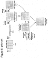
- Figure 2 illustrates a disadvantage of intraframe compression such as shown in Figure 1 .
- exploitation of redundancy between blocks of the key frame is limited to prediction of a subset of frequency coefficients (e.g., the DC coefficient and the left column (or top row) of AC coefficients) from the left (220) or top (230) neighboring block of a block (210).
- the DC coefficient represents the average of the block
- the left column of AC coefficients represents the averages of the rows of a block
- the top row represents the averages of the columns.
- prediction of DC and AC coefficients as in WMV7 limits extrapolation to the row-wise (or column-wise) average signals of the left (or top) neighboring block.
- the AC coefficients in the left DCT coefficient column for the left block (220) are used to predict the entire corresponding row (211) of the block (210).
- Interframe compression in the WMV7 encoder uses block-based motion compensated prediction coding followed by transform coding of the residual error.
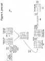
- Figures 3 and 4 illustrate the block-based interframe compression for a predicted frame in the WMV7 encoder.
- Figure 3 illustrates motion estimation for a predicted frame (310)
- Figure 4 illustrates compression of a prediction residual for a motion-estimated block of a predicted frame.
- the WMV7 encoder splits a predicted frame into 8x8 blocks of pixels. Groups of 4 8x8 blocks form macroblocks. For each macroblock, a motion estimation process is performed. The motion estimation approximates the motion of the macroblock of pixels relative to a reference frame, for example, a previously coded, preceding frame.
- the WMV7 encoder computes a motion vector for a macroblock (315) in the predicted frame (310). To compute the motion vector, the encoder searches in a search area (335) of a reference frame (330). Within the search area (335), the encoder compares the macroblock (315) from the predicted frame (310) to various candidate macroblocks in order to find a candidate macroblock that is a good match.
- the encoder can check candidate macroblocks every pixel or every 1 ⁇ 2 pixel in the search area (335), depending on the desired motion estimation resolution for the encoder. Other video encoders check at other increments, for example, every 1 ⁇ 4 pixel.
- For a candidate macroblock the encoder checks the difference between the macroblock (315) of the predicted frame (310) and the candidate macroblock and the cost of encoding the motion vector for that macroblock. After the encoder finds a good matching macroblock, the block matching process ends. The encoder outputs the motion vector (entropy coded) for the matching macroblock so the decoder can find the matching macroblock during decoding.
- a decoder When decoding the predicted frame (310), a decoder uses the motion vector to compute a prediction macroblock for the macroblock (315) using information from the reference frame (330).
- the prediction for the macroblock (315) is rarely perfect, so the encoder usually encodes 8x8 blocks of pixel differences (also called the error or residual blocks) between the prediction macroblock and the macroblock (315) itself.
- Figure 4 illustrates the computation and encoding of an error block (435) for a motion-estimated block in the WMV7 encoder.
- the error block (435) is the difference between the predicted block (415) and the original current block (425).
- the encoder applies a DCT (440) to error block (435), resulting in 8x8 block (445) of coefficients. Even more than was the case with DCT coefficients for pixel values, the significant information for the error block (435) is concentrated in low frequency coefficients (conventionally, the upper left of the block (445)) and many of the high frequency coefficients have values of zero or close to zero (conventionally, the lower right of the block (445)).
- the encoder then quantizes (450) the DCT coefficients, resulting in an 8x8 block of quantized DCT coefficients (455).
- the quantization step size is adjustable. Again, since low frequency DCT coefficients tend to have higher values, quantization results in loss of precision, but not complete loss of the information for the coefficients. On the other hand, since high frequency DCT coefficients tend to have values of zero or close to zero, quantization of the high frequency coefficients results in contiguous regions of zero values. In addition, in some cases high frequency DCT coefficients are quantized more coarsely than low frequency DCT coefficients, resulting in greater loss of precision/information for the high frequency DCT coefficients.
- the encoder then prepares the 8x8 block (455) of quantized DCT coefficients for entropy encoding.
- the encoder scans (460) the 8x8 block (455) into a one dimensional array (465) with 64 elements, such that coefficients are generally ordered from lowest frequency to highest frequency, which typical creates long runs of zero values.
- the encoder entropy encodes the scanned coefficients using a variation of run length coding (470).
- the encoder selects an entropy code from one or more run/level/last tables (475) and outputs the entropy code.
- the encoder uses a 1-bit skip macroblock flag for the macroblock. For many kinds of video content (e.g., low motion and/or low bitrate video), this reduces bitrate by avoiding the transmission of motion vector and residual block information.
- the encoder puts the skip macroblock flag for a macroblock at the macroblock layer in the output bitstream, along with other information for the macroblock.
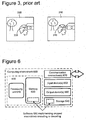
- Figure 5 shows the decoding process (500) for an inter-coded block. Due to the quantization of the DCT coefficients, the reconstructed block (575) is not identical to the corresponding original block. The compression is lossy.
- a decoder decodes (510, 520) entropy-coded information representing a prediction residual using variable length decoding and one or more run/level/last tables (515).
- the decoder inverse scans (530) a one-dimensional array (525) storing the entropy-decoded information into a two-dimensional block (535).
- the decoder inverse quantizes and inverse discrete cosine transforms (together, 540) the data, resulting in a reconstructed error block (545).
- the decoder computes a predicted block (565) using motion vector information (555) for displacement from a reference frame.
- the decoder combines (570) the predicted block (555) with the reconstructed error block (545) to form the reconstructed block (575).
- the decoder When the decoder receives a skip macroblock flag for a macroblock, the decoder skips computing a prediction and decoding residual block information for the macroblock. Instead, the decoder uses corresponding pixel data from the location of the macroblock in the reference frame.
- the amount of change between the original and reconstructed frame is termed the distortion and the number of bits required to code the frame is termed the rate.
- the amount of distortion is roughly inversely proportional to the rate. In other words, coding a frame with fewer bits (greater compression) will result in greater distortion and vice versa.
- One of the goals of a video compression scheme is to try to improve the rate-distortion- in other words to try to achieve the same distortion using fewer bits (or the same bits and lower distortion).
- skip macroblock flags in WMV7 typically reduces bitrate for many kinds of video content, it is less than optimal in some circumstances. In many cases, it fails to exploit redundancy in skip macroblock flags from macroblock to macroblock, for example, when skipped macroblocks occur in bunches in a picture. Also, WMV7 ignores motion prediction for macroblocks in predicted frames when the macroblocks are skipped, which hurts the efficiency of compression of predicted frames in some cases.
- WMV7 Aside from WMV7, several international standards relate to video compression and decompression. These standards include the Motion Picture Experts Group ["MPEG”] 1, 2, and 4 standards and the H.261, H.262, and H.263 standards from the International Telecommunication Union ["ITU"]. Like WMV7, these standards use a combination of intraframe and interframe compression, although the standards typically differ from WMV7 in the details of the compression techniques used.
- MPEG Motion Picture Experts Group
- H.261, H.262, and H.263 from the International Telecommunication Union ["ITU”
- ITU International Telecommunication Union
- the skipped macroblock coding in the above standards typically reduces bitrate for many kinds of video content, but is less than optimal in some circumstances. In many cases, it fails to exploit redundancy in skip macroblock flags from macroblock to macroblock, for example, when skipped macroblocks occur in bunches in a picture. Also, it ignores motion prediction for macroblocks in predicted macroblocks/pictures when the macroblocks are skipped, which hurts the efficiency of compression of predicted macroblocks/pictures in some cases.
- US 5, 552, 832 relates to video signal processing to generate compressed video signals that can be transmitted under the bandwidth constraints of public switched telephone network connections and then decompressed in real time by a PC system to provide satisfactory audio and video conferencing.
- the video image signals are encoded based on blocks of 8x8 pixels where each block may be encoded as skipped, intra or inter blocks. A block is skipped if the sum of the absolute values of the quantized DCT coefficient differences for a given block is less than a specified dead-band threshold.
- a frame header includes a frame type code (FTC) that indicates whether the frame is a mixed frame (with inter, intra, and skipped blocks), a predicted frame (with only inter and skipped blocks) or a reference frame (with only intra blocks).
- FTC frame type code
- a frame body For mixed frames, a frame body consists of bits that define the block type (i.e., intra, inter, or skipped) and the quantized DCT coefficients (or quantized DCT coefficient differences) for each (8x8) block in the current frame. Further, block types are run-length encoded by scanning following a specified block scanning pattern. A scanned pattern may be hard-coded into the encoder and decoder as look-up tables, or the encoder and decoder may have a variety of pre-defined scan patterns for each frame size. Hsu P. et al, "A low bit-rate video codec based on two-dimensional mesh motion compensation with adaptive interpolation", IEEE Transactions on circuits and systems for video technology, Volume 11, no.
- the interpolation pattern consists of two regions where each region contains two node motion vectors, whereby the second configuration describes one region containing three node motion vectors and one region containing only one node motion vector.
- a classification matrix serves the purpose of indicating the locations where new interpolation patterns have been used and a string of indices to notify the decoder of the actual interpolation patterns introduced by the encoder.
- a fixed raster scan of the classification matrix in the encoder and decoder is employed.
- the detailed description is directed to various techniques and tools for encoding and decoding (e.g., in a video encoder/decoder) binary information.
- the binary information may comprise bits indicating whether a video encoder or decoder skips certain macroblocks in a video frame.
- the binary information may comprise bits indicating motion vector resolution for macroblocks (e.g. 1-MV or 4-MV), interlace mode (e.g., field or frame), or some other information.
- Binary information may be encoded on a frame-by-frame basis or on some other basis.
- the binary information is arranged in a bit plane.
- the bit plane is coded at the picture/frame layer.
- the binary information is arranged in some other way and/or coded at a different layer.
- the encoder and decoder process the binary information.
- the binary information may comprise macroblock-level information.
- the encoder and decoder process bit planes of block-level, sub-block-level, or pixel-level information.
- the encoder and decoder switch coding modes.
- the encoder and decoder use normal, row-skip, or column-skip mode.
- the different modes allow the encoder and decoder to exploit redundancy in the binary information.
- the encoder and decoder use other and/or additional modes such as differential modes.
- the encoder and decoder may use a bit plane inversion technique in some modes.
- the encoder and decoder define a skipped macroblock as a predicted macroblock whose motion is equal to its causally predicted motion and which has zero residual error.
- the encoder and decoder define a skipped macroblock as a predicted macroblock with zero motion and zero residual error.
- the encoder and decoder use a raw coding mode to allow for low-latency applications. For example, in the raw coding mode, encoded macroblocks can be transmitted to the decoder right away, without having to wait until all macroblocks in the frame/picture are encoded.
- the encoder and decoder can switch between the raw coding mode and other modes.
- the various techniques and tools can be used in combination or independently.
- the application describes two implementations of skipped macroblock encoding and decoding, along with corresponding bitstream syntaxes.
- Different embodiments implement one or more of the described techniques and tools.
- Described embodiments relate to techniques and tools for encoding and decoding (e.g., in a video encoder/decoder) binary information.
- the binary information may comprise bits indicating whether a video encoder or decoder skips certain macroblocks in a video frame.
- the binary information may comprise bits indicating motion vector resolution for macroblocks (e.g. 1-MV or 4-MV), interlace mode (e.g., field or frame), or some other information.
- Binary information may be encoded on a frame-by-frame basis or on some other basis.
- the binary information is arranged in a bit plane.
- the bit plane is coded at the picture/frame layer.
- the binary information is arranged in some other way and/or coded at a different layer.
- the encoder and decoder switch coding modes.
- the encoder and decoder use normal, row-skip, or column-skip modes.
- the different modes allow the encoder and decoder to exploit redundancy in the binary information.
- the encoder and decoder use other and/or additional modes.
- the encoder and decoder define a skipped macroblock as a predicted macroblock whose motion is equal to its causally predicted motion and which has zero residual error.
- the encoder and decoder define a skipped macroblock as a predicted macroblock with zero motion and zero residual error.
- a raw coding mode is permitted to allow for low-latency applications.
- encoded macroblocks can be transmitted to the decoder right away, without having to wait until all macroblocks in the frame/picture are encoded.
- the encoder and decoder process bit planes of macroblock level information.
- the encoder and decoder process bit planes of block, sub-block, or pixel-level information.
- the various techniques and tools can be used in combination or independently.
- the application describes two implementations of skipped macroblock encoding and decoding, along with corresponding bitstream syntaxes.
- Different embodiments implement one or more of the described techniques and tools.
- the video encoder and decoder perform various techniques. Although the operations for these techniques are typically described in a particular, sequential order for the sake of presentation, it should be understood that this manner of description encompasses minor rearrangements in the order of operations, unless a particular ordering is required. For example, operations described sequentially may in some cases be rearranged or performed concurrently. Moreover, for the sake of simplicity, flowcharts typically do not show the various ways in which particular techniques can be used in conjunction with other techniques.
- the video encoder and decoder use various flags and signals in a bitstream. While specific flags and signals are described, it should be understood that this manner of description encompasses different conventions (e.g., 0's rather than 1's) for the flags and signals.
- FIG. 6 illustrates a generalized example of a suitable computing environment (600) in which several of the described embodiments may be implemented:
- the computing environment (600) is not intended to suggest any limitation as to scope of use or functionality, as the techniques and tools may be implemented in diverse general-purpose or special-purpose computing environments.
- the computing environment (600) includes at least one processing unit (610) and memory (620).
- the processing unit (610) executes computer-executable instructions and may be a real or a virtual processor. In a multi-processing system, multiple processing units execute computer-executable instructions to increase processing power.
- the memory (620) may be volatile memory (e.g., registers, cache, RAM), non-volatile memory (e.g., ROM, EEPROM, flash memory, etc.), or some combination of the two.
- the memory (620) stores software (680) implementing an encoder or decoder, such as a video encoder or decoder.
- a computing environment may have additional features.
- the computing environment (600) includes storage (640), one or more input devices (650), one or more output devices (660), and one or more communication connections (670).
- An interconnection mechanism such as a bus, controller, or network interconnects the components of the computing environment (600).
- operating system software provides an operating environment for other software executing in the computing environment (600), and coordinates activities of the components of the computing environment (600).
- the storage (640) may be removable or non-removable, and includes magnetic disks, magnetic tapes or cassettes, CD-ROMs, DVDs, or any other medium which can be used to store information and which can be accessed within the computing environment (600).
- the storage (640) stores instructions for the software (680) implementing the encoder or decoder.
- the input device(s) (650) may be a touch input device such as a keyboard, mouse, pen, or trackball, a voice input device, a scanning device, or another device that provides input to the computing environment (600).
- the input device(s) (650) may be a sound card, video card, TV tuner card, or similar device that accepts audio or video input in analog or digital form, or a CD-ROM or CD-RW that reads audio or video samples into the computing environment (600).
- the output device(s) (660) may be a display, printer, speaker, CD-writer, or another device that provides output from the computing environment (600).
- the communication connection(s) (670) enable communication over a communication medium to another computing entity.
- the communication medium conveys information such as computer-executable instructions, audio or video input or output, or other data in a modulated data signal.
- a modulated data signal is a signal that has one or more of its characteristics set or changed in such a manner as to encode information in the signal.
- communication media include wired or wireless techniques implemented with an electrical, optical, RF, infrared, acoustic, or other carrier.
- Computer-readable media are any available media that can be accessed within a computing environment.
- Computer-readable media include memory (620), storage (640), communication media, and combinations of any of the above.
- program modules include routines, programs, libraries, objects, classes, components, data structures, etc. that perform particular tasks or implement particular abstract data types.
- the functionality of the program modules may be combined or split between program modules as desired in various embodiments.
- Computer-executable instructions for program modules may be executed within a local or distributed computing environment.
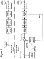
- Figure 7 is a block diagram of a generalized video encoder (700) and Figure 8 is a block diagram of a generalized video decoder (800).
- FIG. 7 and 8 usually do not show side information indicating the encoder settings, modes, tables, etc. used for a video sequence, frame, macroblock, block, etc. Such side information is sent in the output bitstream, typically after entropy encoding of the side information.
- the format of the output bitstream can be Windows Media Video version 8 format or another format.
- the encoder (700) and decoder (800) are block-based and use a 4:2:0 macroblock format with each macroblock including 4 luminance 8x8 luminance blocks (at times treated as one 16x16 macroblock) and two 8x8 chrominance blocks.
- the encoder (700) and decoder (800) are object-based, use a different macroblock or block format, or perform operations on sets of pixels of different size or configuration than 8x8 blacks and 16x16 macroblocks.
- modules of the encoder or decoder can be added, omitted, split into multiple modules, combined with other modules, and/or replaced with like modules.
- encoder or decoders with different modules and/or other configurations of modules perform one or more of the described techniques.
- Figure 7 is a block diagram of a general video encoder system (700).
- the encoder system (700) receives a sequence of video frames including a current frame (705), and produces compressed video information (795) as output.
- Particular embodiments of video encoders typically use a variation or supplemented version of the generalized encoder (700).
- the encoder system (700) compresses predicted frames and key frames.
- Figure 7 shows a path for key frames through the encoder system (700) and a path for forward-predicted frames.
- Many of the components of the encoder system (700) are used for compressing both key frames and predicted frames. The exact operations performed by those components can vary depending on the type of information being compressed.
- a predicted frame (also called p-frame, b-frame for bi-directional prediction, or inter-coded frame] is represented in terms of prediction (or difference) from one or more other frames.
- a prediction residual is the difference between what was predicted and the original frame.
- a key frame also called i-frame, intra-coded frame
- a motion estimator (710) estimates motion of macroblocks or other sets of pixels of the current frame (705) with respect to a reference frame, which is the reconstructed previous frame (725) buffered in the frame store (720).
- the reference frame is a later frame or the current frame is bi-directionally predicted.
- the motion estimator (710) can estimate motion by pixel, 1 ⁇ 2 pixel, 1 ⁇ 4 pixel, or other increments, and can switch the resolution of the motion estimation on a frame-by-frame basis or other basis. The resolution of the motion estimation can be the same or different horizontally and vertically.
- the motion estimator (710) outputs as side information motion information (715) such as motion vectors.
- a motion compensator (730) applies the motion information (715) to the reconstructed previous frame (725) to form a motion-compensated current frame (735).
- the prediction is rarely perfect, however, and the difference between the motion-compensated current frame (735) and the original current frame (705) is the prediction residual (745).
- a motion estimator and motion compensator apply another type of motion estimation/compensation.
- a frequency transformer (760) converts the spatial domain video information into frequency domain (i.e., spectral) data.
- the frequency transformer (760) applies a discrete cosine transform ["DCT"] or variant of DCT to blocks of the pixel data or prediction residual data, producing blocks of DCT coefficients.
- the frequency transformer (760) applies another conventional frequency transform such as a Fourier transform or uses wavelet or subband analysis.
- the frequency transformer (760) can apply a re-oriented frequency transform such as a skewed DCT to blocks of prediction residuals for the key frame.
- the frequency transformer (760) applies an 8x8, 8x4, 4x8, or other size frequency transforms (e.g., DCT) to prediction residuals for predicted frames.
- a quantizer (770) then quantizes the blocks of spectral data coefficients.
- the quantizer applies uniform, scalar quantization to the spectral data with a step-size that varies on a frame-by-frame basis or other basis.
- the quantizer applies another type of quantization to the spectral data coefficients, for example, a non-uniform, vector, or non-adaptive quantization, or directly quantizes spatial domain data in an encoder system that does not use frequency transformations.
- the encoder (700) can use frame dropping, adaptive filtering, or other techniques for rate control.
- the encoder (700) may encode the macroblock as a skipped macroblock. If so, the encoder signals the skipped macroblock in the output bitstream of compressed video information (795).
- an inverse quantizer (776) performs inverse quantization on the quantized spectral data coefficients.
- An inverse frequency transformer (766) then performs the inverse of the operations of the frequency transformer (760), producing a reconstructed prediction residual (for a predicted frame) or a reconstructed key frame. If the current frame (705) was a key frame, the reconstructed key frame is taken as the reconstructed current frame (not shown). If the current frame (705) was a predicted frame, the reconstructed prediction residual is added to the motion-compensated current frame (735) to form the reconstructed current frame.
- the frame store (720) buffers the reconstructed current frame for use in predicting the next frame.
- the encoder applies a deblocking filter to the reconstructed frame to adaptively smooth discontinuities in the blocks of the frame.
- the entropy coder (780) compresses the output of the quantizer (770) as well as certain side information (e.g., motion information (715), spatial extrapolation modes, quantization step size).
- Typical entropy coding techniques include arithmetic coding, differential coding, Huffman coding, run length coding, LZ coding, dictionary coding, and combinations of the above.
- the entropy coder (780) typically uses different coding techniques for different kinds of information (e.g., DC coefficients, AC coefficients, different kinds of side information), and can choose from among multiple code tables within a particular coding technique.
- the entropy coder (780) puts compressed video information (795) in the buffer (790).
- a buffer level indicator is fed back to bit rate adaptive modules.
- the compressed video information (795) is depleted from the buffer (790) at a constant or relatively constant bit rate and stored for subsequent streaming at that bit rate. Therefore, the level of the buffer (790) is primarily a function of the entropy of the filtered, quantized video information, which affects the efficiency of the entropy coding.
- the encoder system (700) streams compressed video information immediately following compression, and the level of the buffer (790) also depends on the rate at which information is depleted from the buffer (790) for transmission.
- the compressed video information (795) can be channel coded for transmission over the network.
- the channel coding can apply error detection and correction data to the compressed video information (795).
- FIG 8 is a block diagram of a general video decoder system (800).
- the decoder system (800) receives information (895) for a compressed sequence of video frames and produces output including a reconstructed frame (805).
- Particular embodiments of video decoders typically use a variation or supplemented version of the generalized decoder (800).
- the decoder system (800) decompresses predicted frames and key frames.
- Figure 8 shows a path for key frames through the decoder system (800) and a path for forward-predicted frames.
- Many of the components of the decoder system (800) are used for compressing both key frames and predicted frames. The exact operations performed by those components can vary depending on the type of information being compressed.
- a buffer (890) receives the information (895) for the compressed video sequence and makes the received information available to the entropy decoder (880).
- the buffer (890) typically receives the information at a rate that is fairly constant over time, and includes a jitter buffer to smooth short-term variations in bandwidth or transmission.
- the buffer (890) can include a playback buffer and other buffers as well. Alternatively, the buffer (890) receives information at a varying rate. Before or after the buffer (890), the compressed video information can be channel decoded and processed for error detection and correction.
- the entropy decoder (880) entropy decodes entropy-coded quantized data as well as entropy-coded side information (e.g., motion information (815), spatial extrapolation modes, quantization step size), typically applying the inverse of the entropy encoding performed in the encoder.
- Entropy decoding techniques include arithmetic decoding, differential decoding, Huffman decoding, run length decoding, LZ decoding, dictionary decoding, and combinations of the above.
- the entropy decoder (880) frequently uses different decoding techniques for different kinds of information (e.g., DC coefficients, AC coefficients, different kinds of side information), and can choose from among multiple code tables within a particular decoding technique.
- a motion compensator (830) applies motion information (815) to a reference frame (825) to form a prediction (835) of the frame (805) being reconstructed.
- the motion compensator (830) uses a macroblock motion vector to find a macroblock in the reference frame (825).
- a frame buffer (820) stores previous reconstructed frames for use as reference frames.
- the motion compensator (830) can compensate for motion at pixel, 1 ⁇ 2 pixel, 1 ⁇ 4 pixel, or other increments, and can switch the resolution of the motion compensation on a frame-by-frame basis or other basis.
- the resolution of the motion compensation can be the same or different horizontally and vertically.
- a motion compensator applies another type of motion compensation.
- the prediction by the motion compensator is rarely perfect, so the decoder (800) also reconstructs prediction residuals.
- the frame store (820) buffers the reconstructed frame for use in predicting the next frame.
- the encoder applies a deblocking filter to the reconstructed frame to adaptively smooth discontinuities in the blocks of the frame.
- An inverse quantizer (870) inverse quantizes entropy-decoded data.
- the inverse quantizer applies uniform, scalar inverse quantization to the entropy-decoded data with a step-size that varies on a frame-by-frame basis or other basis.
- the inverse quantizer applies another type of inverse quantization to the data, for example, a non-uniform, vector, or non-adaptive quantization, or directly inverse quantizes spatial domain data in a decoder system that does not use inverse frequency transformations.
- An inverse frequency transformer (860) converts the quantized, frequency domain data into spatial domain video information.
- the inverse frequency transformer (860) applies an inverse DCT ["IDCT"] or variant of IDCT to blocks of the DCT coefficients, producing pixel data or prediction residual data for key frames or predicted frames, respectively.
- the frequency transformer (860) applies another conventional inverse frequency transform such as a Fourier transform or uses wavelet or subband synthesis.
- the inverse frequency transformer (860) can apply a re-oriented inverse frequency transform such as a skewed IDCT to blocks of prediction residuals for the key frame.
- the inverse frequency transformer (860) applies an 8x8, 8x4, 4x8, or other size inverse frequency transforms (e.g., IDCT) to prediction residuals for predicted frames.
- the decoder (800) reconstructs the skipped macroblock without using the information (e.g., motion information and/or residual information) normally included in the bitstream for non-skipped macroblocks.
- a video encoder and decoder encode and decode, respectively, skipped macroblock information with improved efficiency.
- the skipped macroblock information is signaled at the picture layer in the video bitstream, which allows the encoder to exploit redundancy in the skipped macroblock information.
- the encoder and decoder select between multiple coding modes for encoding and decoding the skipped macroblock information.
- a compressed video sequence is made up of data structured into four hierarchical layers. From top to bottom the layers are: 1) sequence layer; 2) picture layer; 3) macroblock layer; and 4) block layer.
- data for each picture consists of a picture header followed by data for the macroblock layer.
- data for each macroblock consists of a macroblock header followed by the block layer.
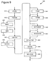
- Figure 9 shows the bitstream elements that make up the P-picture layer (900).
- Table 1 briefly describes the bitstream elements of the P-picture layer (900).
- Table 1 Bitstream elements of the P-picture layer in first implementation Field Description PTYPE (910) Picture type PQUANT (912) Picture quantizer scale SMBC (920) Skipped macroblock code SMB (930) Skipped macroblock field CPBTAB (940) Coded block pattern table MVRES (942) Motion vector resolution TTMBF (944) Macroblock-level transform type flag TTFRM (946) Frame-level transform type DCTACMBF (948) Macroblock-level DCT AC coding set flag DCTACFRM (950) Frame-level DCT AC coding set index DCTDCTAB (952) Intra DCT DC table MVTAB (954) Motion vector table MB LAYER (960) Macroblock layer
- Field Description PTYPE 910) Picture type PQUANT (912) Picture quantizer scale SMBC (920) Skipped macroblock code SMB (930) Skipped macroblock field
- the P-picture layer (900) includes a Skipped Macroblock field (“SMB”) (930) for the macroblocks, in the P picture as well as a Skipped Macroblock Code (“SMBC”) field (920) that signals the coding mode for the skipped macroblock field (930).
- SMB Skipped Macroblock field
- SMBC Skipped Macroblock Code
- the SMBC field (920) is present only in P-picture headers.
- SMBC (920) is a 2-bit value that signals one of four modes used for indicating the skipped macroblocks in the frame.
- the fixed length codes (“FLCs”) for the skipped macroblock coding modes are as follows: Table 2: Skipped macroblock coding mode code table in first implementation, SMBC FLC Skipped Bit Coding Mode 00 No skipped bit coding 01 Normal skipped bit coding 10 Row-prediction (or, "row-skip”) skipped bit coding 11 Column-prediction (or, "column-skip”) skipped bit coding
- the next field in the bitstream is the SMB field (930) containing the skipped macroblock information. So, the SMB field is present only in P-picture headers and only if SMBC signals normal, row-prediction, or column-prediction skipped macroblock coding. If SMBC signals normal coding, then the size of the SMB field is equal to the number of macroblocks in the frame. If SMBC signals row-prediction or column-prediction, then the size of the SMB is variable as described below.
- the skipped macroblock information informs the decoder as to which macroblocks in the frame are not present in the macroblock layer. For these macroblocks, the decoder will copy the corresponding macroblock pixel data from the reference frame when reconstructing that macroblock.
- the SMBC field (920) signals the coding mode for the skipped macroblock field (930). More generally, Figure 10 shows a technique (1000) for encoding skipped macroblock information in a video encoder having multiple skip-macroblock coding modes. Figure 11 shows a corresponding technique (1100) for decoding skipped macroblock information encoded by a video encoder having plural skip-macroblock coding modes.
- the encoder selects a skip-macroblock coding mode for coding skipped macroblock information (1010).
- the skipped macroblock coding modes include a mode where no macroblocks are skipped, a normal mode, a row-prediction (or, "row-skip") mode, and a column-prediction (or "column-skip") mode.
- the encoder encodes the skipped macroblock information (1020).
- the encoder selects coding modes on a picture-by-picture basis. Alternatively, the encoder selects coding modes on some other basis (e.g., at the sequence level). When the encoder is done encoding the skipped macroblock information (1030), encoding ends.
- the decoder determines the skip-macroblock coding mode used by the encoder to encode the skipped macroblock information (1110). The decoder then decodes the skipped macroblock information (1120). The decoder determines coding modes on a picture-by-picture basis. Alternatively, the decoder determines coding modes on some other basis (e.g., at the sequence level). When the decoder is done decoding the skipped macroblock information (1130), decoding ends.
- the skipped macroblock coding modes include a mode where no macroblocks are skipped, a normal mode, a row-prediction (or, "row-skip”) mode, and a column-prediction (or "column-skip”) mode.
- a mode where no macroblocks are skipped a normal mode
- a row-prediction (or, "row-skip") mode a row-prediction (or, "row-skip") mode
- a column-prediction or "column-skip” mode.
- the skipped/not-skipped status of each macroblock is represented with a bit. Therefore, the size of the SMB field in bits is equal to the number of macroblocks in the frame.
- the bit position within the SMB field corresponds to the raster scan order of the macroblocks within the frame starting with the upper-left macroblock. A bit value of 0 indicates that the corresponding macroblock is not skipped; a bit value of 1 indicates that the corresponding macroblock is skipped.
- Figure 13 shows a technique (1300) for encoding in normal skip-macroblock coding mode.
- the encoder checks whether coding of a macroblock will be skipped (1310). If so, the encoder adds a bit value of 1 to the SMB field to indicate that the corresponding macroblock is skipped (1320). Otherwise, the encoder adds a bit value of 0 to the SMB field to indicate that the corresponding macroblock is not skipped (1330). When the encoder is done adding bits to the SMB field (1340), skip macroblock coding ends.
- the SMB field for the example frame (1200) in Figure 12 would be encoded as: 010010111111111111010010.
- each macroblock row In row-prediction mode, the status of each macroblock row (from top to bottom) is indicated with a bit. If the bit is 1, then the row contains all skipped macroblocks and the status for the next row follows. If the bit equals 0, then the skipped/not skipped status for each macroblock in that row is signaled with a bit. Therefore, a bit field equal in length to the number of macroblocks in a row follows. The bits in the bit field represent the macroblocks in left-to-right order. Again, a value of 0 indicates that the corresponding macroblock is not skipped; a value of 1 indicates that the corresponding macroblock is skipped.
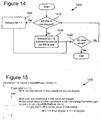
- Figure 14 shows a technique (1400) for encoding in row-prediction (or, "row-skip") macroblock coding mode.
- the encoder checks if a row contains all skipped macroblocks (1410). If so, the encoder adds an indicator bit of 1 to the SMB field (1420) and the status for the next row follows. If the row does not contain all skipped macroblocks, the encoder adds an indicator bit of 0 to the SMB field, and the skipped/not-skipped status for each macroblock in that row is signaled with a bit (1430).
- the encoder is done with all the rows in the frame (1440), the row-prediction encoding ends.
- Figure 15 shows pseudo-code (1500) illustrating row-prediction decoding of the skipped macroblock information.
- the function get_bits(n) reads n bits from the bitstream and returns the value.
- the SMB field for the example frame (1200) in Figure 12 would be encoded as: 0010010110010010.
- each macroblock column In column-prediction mode, the status of each macroblock column (from left to right) is indicated with a bit. If the bit is 1, then the column contains all skipped macroblocks and the status for the next column follows. If the bit equals 0, then the skipped/not skipped status for each macroblock in that column is signaled with a bit. Therefore, a bit field equal in length to the number of macroblocks in a column follow. The bits in the bit field represent the macroblocks in top-to-bottom order. Again, a value of 0 indicates that the corresponding macroblock is not skipped; a value of 1 indicates that the corresponding macroblock is skipped.
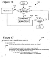
- Figure 16 shows a technique (1600) for encoding in column-prediction (or, "column-skip") macroblock coding mode.
- the encoder checks if the column contains all skipped macroblocks (1610). If so, the encoder adds an indicator bit of 1 to the SMB field (1620) and the status for the next column follows. If the column does not contain all skipped macroblocks, the encoder adds an indicator bit of 0 to the SMB field, and the skipped/not-skipped status for each macroblock in that column is signaled with a bit (1630).
- the encoder is done with all the columns in the frame (1640), the column-prediction encoding ends.
- Figure 17 shows pseudo-code (1700) illustrating column-prediction decoding of the skipped macroblock information.
- the SMB field for the example frame (1200) in Figure 12 would be encoded as: 0011010011000110100110.
- a video encoder and decoder encode and decode, respectively, skipped macroblock information and/or other 2-D binary data with improved efficiency.
- the encoder and decoder define a skipped macroblock as having a default motion (not necessarily zero motion), which allows the encoder and decoder to skip more macroblocks in many cases.
- Efficient frame-level coding of bit planes indicates skipped macroblock information and/or other 2-D binary data.
- the encoder and decoder may use a raw (MB-level) coding option of skipped macroblocks for low-latency applications.
- the second implementation includes a new definition of the concept of a skipped macroblock.
- "Skip" refers to a condition in a bitstream where no further information needs to be transmitted at that level of granularity.
- a skipped macroblock is a macroblock (block) that has a default type, default motion, and default residual error. (In comparison, in other implementations and standards, skipped macroblocks are predicted macroblocks with zero motion and zero residuals.
- the new definition of skipped macroblock is a predicted macroblock whose motion is equal to its causally predicted motion, and which has zero residual error. (The point of difference from the other definition is the default motion is equal to the motion predictor, and this may not necessarily be zero.)
- predicted motion vectors for a current macroblock are taken from the macroblock directly above or directly to the left of the current macroblock.
- horizontal and vertical components of the predictor are generated from the horizontal and vertical component-wise medians of the macroblocks the left, top, and top right of the current macroblock.
- the motion vectors of a skipped macroblock with four motion vectors (4MV) are given by their predictions performed sequentially in the natural scan order. As with the one motion vector (1 MV) case, the error residuals are zero.
- Figure 18 shows a technique (1800) for determining whether to skip coding of particular macroblocks in a video encoder according to the new definition of skipped macroblocks.
- the encoder checks whether the current frame is an I-frame or a P-frame (1810). If the current frame is an I-frame, no macroblocks in the current frame are skipped (1820), and skip-macroblock coding for the frame ends.
- the encoder checks for macroblocks in the current frame that can be skipped. For a given macroblock, the encoder checks whether the motion vector for the macroblock is equal to the causally predicted motion vector for the macroblock (e.g., whether the differential motion vector for the macroblock is equal to zero) (1830). If the motion for a macroblock does not equal the causally predicted motion, the encoder does not skip the macroblock (1840). Otherwise, the encoder checks whether there is any residual to be encoded for the macroblock (1850). If there is a residual to be coded, the encoder does not skip the macroblock (1860). If there is no residual for the macroblock, however, the encoder skips the macroblock (1870). The encoder continues to encode or skip macroblocks until encoding is done (1880).
- the causally predicted motion vector for the macroblock e.g., whether the differential motion vector for the macroblock is equal to zero
- certain macroblock-specific information can be encoded in one bit per macroblock.
- the status for all macroblocks in a frame can be coded together as a bit plane and transmitted in the frame header.
- the encoder uses bit plane coding in three cases to signal information about macroblocks in a frame.
- the three cases are: 1) signaling skipped macroblocks, 2) signaling field or frame macroblock mode, and 3) signaling 1-MV or 4-MV motion vector mode for each macroblock.
- This section describes bit plane coding for any of the three cases and corresponding decoding.
- Frame-level bit plane coding is used to encode two-dimensional binary arrays.
- the size of each array is rowMB x coIMB, where rowMB and coIMB are the number of macroblock rows and columns, respectively.
- each array is coded as a set of consecutive bits.
- One of seven modes is used to encode each array, as enumerated in Table 3 and described below.
- Table 3 Coding modes in second implementation Coding Mode Description Raw Coded as one bit per symbol Normal-2 Two symbols coded jointly Diff-2 Differential coding of bit plane, followed by coding two residual symbols jointly Normal-6 Six symbols coded jointly Diff-6 Differential coding of bit plane, followed by coding six residual symbols jointly Row-skip One bit skip to signal rows with no set bits. Column-skip One bit skip to signal columns with no set bits.
- the encoder uses three syntax elements to embed the information in a bit plane: MODE, INVERT and DATABITS.
- the MODE field is a variable length code (“VLC”) that encodes the coding mode for the bit plane.
- VLC variable length code
- the VLC in the MODE field represents any of the seven coding modes enumerated in Table 3.
- the encoder can assign shorter codes to more probable coding modes and longer codes to less probable coding modes.
- the MODE field is transmitted in the frame header.
- the encoder and decoder switch between coding modes on a frame-by-frame basis.
- the encoder and decoder switch between coding modes as like the encoder and decoder of the first implementation switch between skipped macroblock coding modes in Figures 10 and 11 , respectively.
- the encoder and decoder switch using some other technique and/or on some other basis.
- the one bit INVERT field is sent.
- the INVERT field indicates whether the bits in the bit plane are to be inverted before encoding takes place in the encoder and whether the output of decoding in the decoder is to be inverted.
- the INVERT field is 1 when most of the bits in the bit plane are equal to 1, and 0 when most of the bits in the bit plane are equal to 0.
- the encoder employs several coding modes (such as normal-2 and normal-6) that consume less bits when more 0s are present. If the bit plane to be encoded has more 1s than 0s, the encoder can invert the bit plane to increase the proportion of 0s in the bit plane and increase the potential for bit savings. Other modes (such as diff-2 and diff-6) use the value of the INVERT to calculate a predictor bit plane. Therefore, in some coding modes, the final bit plane reconstructed at the decoder depends on INVERT.
- the DATABITS field is an entropy coded stream of VLC symbols containing the information necessary to reconstruct the bit plane, given the MODE and INVERT fields.
- the encoder encodes binary information (e.g., skipped macroblock information) in any of seven different coding modes: row-skip mode, column-skip mode, normal-2 mode, normal-6 mode, diff-2 mode, diff-6 mode, and raw mode.
- a decoder performs corresponding decoding for any of the seven coding modes. Each mode is described in detail below.
- the encoder and decoder use other and/or additional coding modes.
- the row-skip coding mode saves bits by representing a row in a bit plane with a single bit if each binary symbol in the row is of a certain value. For example, the encoder represents a skipped macroblock with a 0 in a bit plane, and uses a row-skip coding mode that represents a row of all 0s with a single bit. The encoder therefore saves bits when entire rows of macroblocks are skipped. The decoder performs corresponding decoding.
- all-zero rows are indicated using one bit set to 0.
- the one bit indicator is set to 1, and this is followed by coIMB bits containing the bit plane row in order. Rows are scanned in the natural order.
- a one-bit flag indicates whether the row or column is all zero. If not the entire row or column is transmitted using one bit per symbol.
- conditional inversion is indicated through the INVERT bit
- the encoder pre-inverts the bit plane before the bit plane is tiled and coded.
- conditional inversion is implemented by taking the inverse of the final output. (This is not performed for the diff-2 and diff-6 mode.)
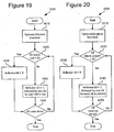
- Figure 19 shows a technique (1900) for encoding binary information in a bit plane in a row-skip coding mode.
- the encoder first checks whether inversion of the bit plane is appropriate, and, if so, performs the inversion (1910). The encoder then checks a row in the bit plane to see if each bit in the row is equal to 0 (1920). If so, the encoder sets the indicator bit for the row to 0 (1930). If any of the bits in the row are not 0, the encoder sets the indicator bit for the row to 1 and encodes each bit in the row with one bit (1940). When the encoder is.done encoding all rows in the bit plane (1950), encoding of the bit plane ends.
- a decoder performs corresponding decoding for the row-skip coding mode.
- Figure 20 shows a technique for encoding binary information in a column-skip coding mode.
- the encoder first checks whether inversion of the bit plane is appropriate, and, if so, performs the inversion (2010). The encoder then checks a column in the bit plane to see if each bit in the column is equal to 0 (2020). If so, the encoder sets the indicator bit for the column to 0 (2030). If any of the bits in the column are not 0, the encoder sets the indicator bit for the column to 1 and encodes each bit in the column with one bit (1940). When the encoder is done encoding all columns in the bit plane (1950), encoding of the bit plane ends.
- a decoder performs corresponding decoding for the column-skip coding mode.
- the encoder uses the normal-2 mode to jointly encode plural binary symbols in a bit plane (e.g., by using a vector Huffman or other variable length encoding scheme).
- the encoder encodes pairs of binary symbols with variable length codes.
- the decoder performs corresponding decoding.
- rowMB x coIMB If rowMB x coIMB is odd, the first symbol is encoded as a single bit. Subsequent symbols are encoded pairwise, in natural scan order. A VLC table is used to encode the symbol pairs to reduce overall entropy.
- conditional inversion When conditional inversion is indicated through the INVERT bit, the encoder pre-inverts the bit plane before the bit plane is coded pairwise. On the decoder side, conditional inversion is implemented by taking the inverse of the final output. (When the diff-2 mode is used, conditional inversion is not performed at this step.)
- Figure 21 shows a technique (2100) for encoding binary information in normal-2 mode.
- the encoder performs an initial check to determine whether inversion of the bit plane is appropriate to improve coding efficiency and, if so, performs the inversion (2110).
- the encoder determines whether the bit plane being coded has an odd number of binary symbols (2120). If so, the encoder encodes the first symbol with a single bit (2130).
- the encoder then encodes symbol pairs with variable length codes, using shorter codes to represent more probable pairs and longer codes to represent less probable pairs (2140). When encoding of the symbol pairs is done (2150), the encoding ends.
- a decoder performs corresponding decoding for the normal-2 coding mode.
- the encoder also uses the normal-6 mode to jointly encode plural binary symbols in a bit plane (e.g., by using a vector Huffman or other variable length encoding scheme).
- the encoder tiles groups of six binary symbols and represents each group with a variable length code.
- the decoder performs corresponding decoding.
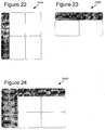
- the bit plane is encoded in groups of six pixels. These pixels are grouped into either 2x3 or 3x2 tiles. The bit plane is tiled maximally using a set of rules, and the remaining pixels are encoded using variants of row-skip and column-skip modes.
- Figures 22, 23 and 24 show examples of frames tiled in the normal-6 coding mode.
- Figure 22 shows a frame (2200) with 3x2 vertical tiles and a 1-symbol wide remainder (shown as a shaded area) to be coded in column-skip mode.
- Figure 23 shows a frame (2300) with 2x3 horizontal tiles and a 1-symbol wide remainder to be coded in row-skip mode.
- Figure 24 shows a frame (2400) with 2x3 horizontal tiles and 1-symbol wide remainders to be coded in row-skip and column-skip modes.
- 3x2 and 2x3 tiles are used in this example, in other embodiments, different configurations of tiles and/or different tiling rules are used.
- the 6-element tiles are encoded first, followed by the column-skip and row-skip encoded linear tiles. If the array size is a multiple of 3x2 or 2x3, the latter linear tiles do not exist and the bit plane is perfectly tiled.
- the 6-element rectangular tiles are encoded using a VLC table.
- conditional inversion When conditional inversion is indicated through the INVERT bit, the encoder pre-inverts the bit plane before the bit plane is tiled and coded. On the decoder side, conditional inversion is implemented by taking the inverse of the final output. (When the diff-6 mode is used, conditional inversion is not performed at this step.)
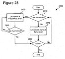
- Figure 25 shows a technique (2500) for encoding binary information in normal-6 mode.
- the encoder performs an initial check to determine whether inversion of the bit plane is appropriate to improve coding efficiency and, if so, performs the inversion (2510).
- the encoder then checks whether the number of rows in the bit plane is a multiple of three (2520). If the number of rows is not a multiple of three, the encoder groups the symbols in the bit plane into 2x3 horizontal tiles (2530).
- the encoder checks whether the number of columns in the bit plane is a multiple of three (2540). If the number of columns is a multiple of three, the encoder groups the symbols in the bit plane into 2x3 horizontal tiles (2530). If the number of columns is not a multiple of three, the encoder groups the symbols into 3x2 vertical tiles (2550).
- the encoder After grouping symbols into 3x2 or 2x3 tiles, the encoder encodes the groups of six tiled symbols using a technique such as a six-dimension vector Huffman coding technique or some other coding technique (2560). The encoder encodes any remaining untiled symbols using the row-skip and/or column-skip coding techniques described above (2570).
- a decoder performs corresponding decoding for the normal-6 coding mode.
- an encoder uses other techniques to code the tiled and untiled symbols.
- Differential coding modes such as diff-2 or diff-6 mode encode bit planes by first generating a bit plane of differential (or residual) bits for the bit plane to be coded, based on a predictor for the bit plane to be coded.
- the residual bit plane is then encoded using, for example, the normal-2 or normal-6 coding mode, without conditional inversion.
- the predictor b ⁇ (i, j) of a given binary symbol b(i, j) will be the binary symbol just to the left b(i -1 ,j) except in the following special cases:
- the residual bit plane is encoded using the normal-2 or normal-6 modes with no conditional inversion.
- Figure 26 shows a technique (2600) for encoding binary information in a differential coding mode.
- the encoder calculates a predictor for a bit plane (2610), for example, as shown in equation 1.
- the encoder then calculates a residual bit plane, for example, by performing an XOR operation on the bit plane and its predictor (2620).
- the encoder then encodes the residual bit plane (e.g., in normal-2 or normal-6 mode) (2630).
- Figure 27 shows a technique (2700) for decoding binary information encoded in a differential coding mode.
- the decoder decodes the residual bit plane (2710) using an appropriate decoding technique, based on the mode used to encode the residual bit plane (e.g., normal-2 or normal-6 mode).
- the decoder also calculates the predictor for the bit plane (2720), using the same technique used in the encoder.
- the decoder then reconstructs the original bit plane, for example, by performing an XOR operation on the decoded residual bit plane and the predictor bit plane (2730).
- All modes except for raw mode encode a bit plane at the frame level which calls for a second pass through the frame during encoding.
- the second pass can add unacceptable delay (e.g., because transmission of the frame header and macroblock layer information is delayed until the last macroblock in the frame is reached, because of the time spent encoding the bit plane).
- the raw mode uses the traditional method of encoding the bit plane one bit per binary symbol at the same location in the bitstream as the rest of the macroblock level information.
- macroblock-level coding of symbols is not a new concept by itself, switching the coding of symbols from frame level to macroblock level provides a low latency alternative to frame-level coding.
- Figure 28 shows a technique (2800) for selectively encoding binary information for a macroblock in raw coding mode for low latency applications.
- the encoder checks whether to use raw mode to encode the binary information (2810). If so, the encoder encodes a bit at the macroblock level for a macroblock (2820) and checks whether the macroblock is the last macroblock in the frame (2830). If the macroblock is not the last macroblock in the frame, the encoder continues by encoding a bit for the next macroblock at the macroblock level (2820).
- the encoder If the encoder does not use the raw coding mode, the encoder encodes a bit plane at the frame level for the macroblocks in the frame (2840). When the encoding of the macroblocks in the frame is done (2850), the encoding ends for the frame.
Landscapes
- Engineering & Computer Science (AREA)
- Multimedia (AREA)
- Signal Processing (AREA)
- Computing Systems (AREA)
- Theoretical Computer Science (AREA)
- Compression Or Coding Systems Of Tv Signals (AREA)
- Compression, Expansion, Code Conversion, And Decoders (AREA)
Description
- The present application claims the benefit of
U.S. Provisional patent Application Serial No. 60/341,674 , entitled "Techniques and Tools for Video Encoding and Decoding," filed December 17, 2001, the disclosure of which is incorporated by reference. The present application also claims the benefit ofU.S. Provisional Patent Application Serial No. 60/377,712 , entitled "Skip Macroblock Coding," filed May 3, 2002, the disclosure of which is incorporated by reference. - Techniques and tools for encoding/decoding binary information in video coding/decoding applications are described. For example, a video encoder encodes skipped macroblock information.
- Digital video consumes large amounts of storage and transmission capacity. A typical raw digital video sequence includes 15 or 30 frames per second. Each frame can include tens or hundreds of thousands of pixels (also called pels). Each pixel represents a tiny element of the picture. In raw form, a computer commonly represents a pixel with 24 bits. Thus, the number of bits per second, or bit rate, of a typical raw digital video sequence can be 5 million bits/second or more.
- Most computers and computer networks lack the resources to process raw digital video. For this reason, engineers use compression (also called coding or encoding) to reduce the bit rate of digital video. Compression can be lossless, in which quality of the video does not suffer but decreases in bit rate are limited by the complexity of the video. Or, compression can be lossy, in which quality of the video suffers but decreases in bit rate are more dramatic. Decompression reverses compression.
- In general, video compression techniques include intraframe compression and interframe compression. Intraframe compression techniques compress individual frames, typically called I-frames, or key frames. Interframe compression techniques compress frames with reference to preceding and/or following frames, and are called typically called predicted frames, P-frames, or B-frames.
- Microsoft Corporation's Windows Media Video, Version 7 ["WMV7"] includes a video encoder and a video decoder. The WMV7 encoder uses intraframe and interframe compression, and the WMV7 decoder uses intraframe and interframe decompression.
-
Figure 1 illustrates block-based intraframe compression (100) of a block (105) of pixels in a key frame in the WMV7 encoder. A block is a set of pixels, for example, an 8x8 arrangement of pixels. The WMV7 encoder splits a key video frame into 8x8 blocks of pixels and applies an 8x8 Discrete Cosine Transform ["DCT"] (110) to individual blocks such as the block (105). A DCT is a type of frequency transform that converts the 8x8 block of pixels (spatial information) into an 8x8 block of DCT coefficients (115), which are frequency information. The DCT operation itself is lossless or nearly lossless. Compared to the original pixel values, however, the DCT coefficients are more efficient for the encoder to compress since most of the significant information is concentrated in low frequency coefficients (conventionally, the upper left of the block (115)) and many of the high frequency coefficients (conventionally, the lower right of the block (115)) have values of zero or close to zero. - The encoder then quantizes (120) the DCT coefficients, resulting in an 8x8 block of quantized DCT coefficients (125). For example, the encoder applies a uniform, scalar quantization step size to each coefficient, which is analogous to dividing each coefficient by the same value and rounding. For example, if a DCT coefficient value is 163 and the step size is 10, the quantized DCT coefficient value is 16. Quantization is lossy. The reconstructed DCT coefficient value will be 160, not 163. Since low frequency DCT coefficients tend to have higher values, quantization results in loss of precision but not complete loss of the information for the coefficients. On the other hand, since high frequency DCT coefficients tend to have values of zero or close to zero, quantization of the high frequency coefficients typically results in contiguous regions of zero values. In addition, in some cases high frequency DCT coefficients are quantized more coarsely than low frequency DCT coefficients, resulting in greater loss of precision/information for the high frequency DCT coefficients.
- The encoder then prepares the 8x8 block of quantized DCT coefficients (125) for entropy encoding, which is a form of lossless compression. The exact type of entropy encoding can vary depending on whether a coefficient is a DC coefficient (lowest frequency), an AC coefficient (other frequencies) in the top row or left column, or another AC coefficient.
- The encoder-encodes the-DC coefficient (126) as a differential from the DC coefficient (136) of a neighboring 8x8 block, which is a previously encoded neighbor (e.g., top or left) of the block being encoded. (
Figure 1 shows a neighbor block (135) that is situated to the left of the block being encoded in the frame.) The encoder entropy encodes (140) the differential. - The entropy encoder can encode the left column or top row of AC coefficients as a differential from a corresponding column or row of the neighboring 8x8 block.
Figure 1 shows the left column (127) of AC coefficients encoded as a differential (147) from the left column (137) of the neighboring (to the left) block (135). The differential coding increases the chance that the differential coefficients have zero values. The remaining AC coefficients are from the block (125) of quantized DCT coefficients. - The encoder scans (150) the 8x8 block (145) of predicted, quantized AC DCT coefficients into a one-dimensional array (155) and then entropy encodes the scanned AC coefficients using a variation of run length coding (160). The encoder selects an entropy code from one or more run/level/last tables (165) and outputs the entropy code.
- A key frame contributes much more to bit rate than a predicted frame. In low or mid-bit rate applications, key frames are often critical bottlenecks for performance, so efficient compression of key frames is critical.
-
Figure 2 illustrates a disadvantage of intraframe compression such as shown inFigure 1 . In particular, exploitation of redundancy between blocks of the key frame is limited to prediction of a subset of frequency coefficients (e.g., the DC coefficient and the left column (or top row) of AC coefficients) from the left (220) or top (230) neighboring block of a block (210). The DC coefficient represents the average of the block, the left column of AC coefficients represents the averages of the rows of a block, and the top row represents the averages of the columns. In effect, prediction of DC and AC coefficients as in WMV7 limits extrapolation to the row-wise (or column-wise) average signals of the left (or top) neighboring block. For a particular row (221) in the left block (220), the AC coefficients in the left DCT coefficient column for the left block (220) are used to predict the entire corresponding row (211) of the block (210). - Interframe compression in the WMV7 encoder uses block-based motion compensated prediction coding followed by transform coding of the residual error.
-
Figures 3 and4 illustrate the block-based interframe compression for a predicted frame in the WMV7 encoder. In particular,Figure 3 illustrates motion estimation for a predicted frame (310) andFigure 4 illustrates compression of a prediction residual for a motion-estimated block of a predicted frame. - The WMV7 encoder splits a predicted frame into 8x8 blocks of pixels. Groups of 4 8x8 blocks form macroblocks. For each macroblock, a motion estimation process is performed. The motion estimation approximates the motion of the macroblock of pixels relative to a reference frame, for example, a previously coded, preceding frame. In
Figure 3 , the WMV7 encoder computes a motion vector for a macroblock (315) in the predicted frame (310). To compute the motion vector, the encoder searches in a search area (335) of a reference frame (330). Within the search area (335), the encoder compares the macroblock (315) from the predicted frame (310) to various candidate macroblocks in order to find a candidate macroblock that is a good match. The encoder can check candidate macroblocks every pixel or every ½ pixel in the search area (335), depending on the desired motion estimation resolution for the encoder. Other video encoders check at other increments, for example, every ¼ pixel. For a candidate macroblock, the encoder checks the difference between the macroblock (315) of the predicted frame (310) and the candidate macroblock and the cost of encoding the motion vector for that macroblock. After the encoder finds a good matching macroblock, the block matching process ends. The encoder outputs the motion vector (entropy coded) for the matching macroblock so the decoder can find the matching macroblock during decoding. When decoding the predicted frame (310), a decoder uses the motion vector to compute a prediction macroblock for the macroblock (315) using information from the reference frame (330). The prediction for the macroblock (315) is rarely perfect, so the encoder usually encodes 8x8 blocks of pixel differences (also called the error or residual blocks) between the prediction macroblock and the macroblock (315) itself. -
Figure 4 illustrates the computation and encoding of an error block (435) for a motion-estimated block in the WMV7 encoder. The error block (435) is the difference between the predicted block (415) and the original current block (425). The encoder applies a DCT (440) to error block (435), resulting in 8x8 block (445) of coefficients. Even more than was the case with DCT coefficients for pixel values, the significant information for the error block (435) is concentrated in low frequency coefficients (conventionally, the upper left of the block (445)) and many of the high frequency coefficients have values of zero or close to zero (conventionally, the lower right of the block (445)). - The encoder then quantizes (450) the DCT coefficients, resulting in an 8x8 block of quantized DCT coefficients (455). The quantization step size is adjustable. Again, since low frequency DCT coefficients tend to have higher values, quantization results in loss of precision, but not complete loss of the information for the coefficients. On the other hand, since high frequency DCT coefficients tend to have values of zero or close to zero, quantization of the high frequency coefficients results in contiguous regions of zero values. In addition, in some cases high frequency DCT coefficients are quantized more coarsely than low frequency DCT coefficients, resulting in greater loss of precision/information for the high frequency DCT coefficients.
- The encoder then prepares the 8x8 block (455) of quantized DCT coefficients for entropy encoding. The encoder scans (460) the 8x8 block (455) into a one dimensional array (465) with 64 elements, such that coefficients are generally ordered from lowest frequency to highest frequency, which typical creates long runs of zero values.
- The encoder entropy encodes the scanned coefficients using a variation of run length coding (470). The encoder selects an entropy code from one or more run/level/last tables (475) and outputs the entropy code.
- When the motion vector for a macroblock is zero (i.e., no motion) and no residual block information is transmitted for the macroblock, the encoder uses a 1-bit skip macroblock flag for the macroblock. For many kinds of video content (e.g., low motion and/or low bitrate video), this reduces bitrate by avoiding the transmission of motion vector and residual block information. The encoder puts the skip macroblock flag for a macroblock at the macroblock layer in the output bitstream, along with other information for the macroblock.
-
Figure 5 shows the decoding process (500) for an inter-coded block. Due to the quantization of the DCT coefficients, the reconstructed block (575) is not identical to the corresponding original block. The compression is lossy. - In summary of
Figure 5 , a decoder decodes (510, 520) entropy-coded information representing a prediction residual using variable length decoding and one or more run/level/last tables (515). The decoder inverse scans (530) a one-dimensional array (525) storing the entropy-decoded information into a two-dimensional block (535). The decoder inverse quantizes and inverse discrete cosine transforms (together, 540) the data, resulting in a reconstructed error block (545). In a separate path, the decoder computes a predicted block (565) using motion vector information (555) for displacement from a reference frame. The decoder combines (570) the predicted block (555) with the reconstructed error block (545) to form the reconstructed block (575). - When the decoder receives a skip macroblock flag for a macroblock, the decoder skips computing a prediction and decoding residual block information for the macroblock. Instead, the decoder uses corresponding pixel data from the location of the macroblock in the reference frame.
- The amount of change between the original and reconstructed frame is termed the distortion and the number of bits required to code the frame is termed the rate. The amount of distortion is roughly inversely proportional to the rate. In other words, coding a frame with fewer bits (greater compression) will result in greater distortion and vice versa. One of the goals of a video compression scheme is to try to improve the rate-distortion- in other words to try to achieve the same distortion using fewer bits (or the same bits and lower distortion).
- Although the use of skip macroblock flags in WMV7 typically reduces bitrate for many kinds of video content, it is less than optimal in some circumstances. In many cases, it fails to exploit redundancy in skip macroblock flags from macroblock to macroblock, for example, when skipped macroblocks occur in bunches in a picture. Also, WMV7 ignores motion prediction for macroblocks in predicted frames when the macroblocks are skipped, which hurts the efficiency of compression of predicted frames in some cases.
- Aside from WMV7, several international standards relate to video compression and decompression. These standards include the Motion Picture Experts Group ["MPEG"] 1, 2, and 4 standards and the H.261, H.262, and H.263 standards from the International Telecommunication Union ["ITU"]. Like WMV7, these standards use a combination of intraframe and interframe compression, although the standards typically differ from WMV7 in the details of the compression techniques used.
- Some international standards recognize skipping coding of macroblocks as a tool to be used in video compression and decompression. For additional detail about skip macroblock coding in the standards, see the standards' specifications themselves.
- The skipped macroblock coding in the above standards typically reduces bitrate for many kinds of video content, but is less than optimal in some circumstances. In many cases, it fails to exploit redundancy in skip macroblock flags from macroblock to macroblock, for example, when skipped macroblocks occur in bunches in a picture. Also, it ignores motion prediction for macroblocks in predicted macroblocks/pictures when the macroblocks are skipped, which hurts the efficiency of compression of predicted macroblocks/pictures in some cases.
- Given the critical importance of video compression and decompression to digital video, it is not surprising that video compression and decompression are richly developed fields. Whatever the benefits of previous video compression and decompression techniques, however, they do not have the advantages of the following techniques and tools.
US 5, 552, 832 relates to video signal processing to generate compressed video signals that can be transmitted under the bandwidth constraints of public switched telephone network connections and then decompressed in real time by a PC system to provide satisfactory audio and video conferencing. The video image signals are encoded based on blocks of 8x8 pixels where each block may be encoded as skipped, intra or inter blocks. A block is skipped if the sum of the absolute values of the quantized DCT coefficient differences for a given block is less than a specified dead-band threshold. If the block composition is changing as a result of an information source, like movement, then the sum will exceed the dead-band threshold within one or two time intervals. If a block is skipped, the decoder will then know to copy the corresponding (8x8) block of DCT coeffcients from the previous decoded frame. Further, a host processor maintains a single DCT coefficient frame buffer. For a skipped block, the corresponding block of the frame buffer is left unchanged from its state for the previous frame. Within a bitstream syntax, a frame header includes a frame type code (FTC) that indicates whether the frame is a mixed frame (with inter, intra, and skipped blocks), a predicted frame (with only inter and skipped blocks) or a reference frame (with only intra blocks). For mixed frames, a frame body consists of bits that define the block type (i.e., intra, inter, or skipped) and the quantized DCT coefficients (or quantized DCT coefficient differences) for each (8x8) block in the current frame. Further, block types are run-length encoded by scanning following a specified block scanning pattern. A scanned pattern may be hard-coded into the encoder and decoder as look-up tables, or the encoder and decoder may have a variety of pre-defined scan patterns for each frame size.
Hsu P. et al, "A low bit-rate video codec based on two-dimensional mesh motion compensation with adaptive interpolation", IEEE Transactions on circuits and systems for video technology, Volume 11, no. 1, 2001 pages 111-117 relates to video coding based on two-dimensional mesh motion estimation and compensation. In particular, for each frame to be coded, the frame and its previous frame is covered with a regular quadrilateral mesh. The nodes of the mesh are spaced 16 pixels apart in both directions. The displacement of the nodes of a frame and its previous frame, i.e., node motion vector, will be used to generate a full motion field patch by patch through bilinear interpolation. In addition to the default bilinear interpolation, 32 new interpolation patterns are introduced, wherein the interpolation patterns are classified into two types of configurations. In the first configuration, the interpolation pattern consists of two regions where each region contains two node motion vectors, whereby the second configuration describes one region containing three node motion vectors and one region containing only one node motion vector. In addition, a classification matrix serves the purpose of indicating the locations where new interpolation patterns have been used and a string of indices to notify the decoder of the actual interpolation patterns introduced by the encoder. To obtain an order of visit for the adaptive interpolated patches, a fixed raster scan of the classification matrix in the encoder and decoder is employed. - It is the object of the invention to have a better compression of video images.
- This object is solved by the invention as claimed in the independent claims.
- Preferred embodiments are defined by the dependent claims.
- In summary, the detailed description is directed to various techniques and tools for encoding and decoding (e.g., in a video encoder/decoder) binary information. The binary information may comprise bits indicating whether a video encoder or decoder skips certain macroblocks in a video frame. Or, the binary information may comprise bits indicating motion vector resolution for macroblocks (e.g. 1-MV or 4-MV), interlace mode (e.g., field or frame), or some other information. Binary information may be encoded on a frame-by-frame basis or on some other basis.
- In some embodiments, the binary information is arranged in a bit plane. For example, the bit plane is coded at the picture/frame layer. Alternatively, the binary information is arranged in some other way and/or coded at a different layer. The encoder and decoder process the binary information. The binary information may comprise macroblock-level information. Alternatively, the encoder and decoder process bit planes of block-level, sub-block-level, or pixel-level information.
- In some embodiments, the encoder and decoder switch coding modes. For example, the encoder and decoder use normal, row-skip, or column-skip mode. The different modes allow the encoder and decoder to exploit redundancy in the binary information. Alternatively, the encoder and decoder use other and/or additional modes such as differential modes. To increase efficiency, the encoder and decoder may use a bit plane inversion technique in some modes.
- In some embodiments, the encoder and decoder define a skipped macroblock as a predicted macroblock whose motion is equal to its causally predicted motion and which has zero residual error. Alternatively, the encoder and decoder define a skipped macroblock as a predicted macroblock with zero motion and zero residual error.
- In some embodiments, the encoder and decoder use a raw coding mode to allow for low-latency applications. For example, in the raw coding mode, encoded macroblocks can be transmitted to the decoder right away, without having to wait until all macroblocks in the frame/picture are encoded. The encoder and decoder can switch between the raw coding mode and other modes.
- The various techniques and tools can be used in combination or independently. In particular, the application describes two implementations of skipped macroblock encoding and decoding, along with corresponding bitstream syntaxes. Different embodiments implement one or more of the described techniques and tools.
- Additional features and advantages will be made apparent from the following detailed description of different embodiments that proceeds with reference to the accompanying drawings.
-
-
Figure 1 is a diagram showing block-based intraframe compression of an 8x8 block of pixels according to prior art. -
Figure 2 is a diagram showing prediction of frequency coefficients according to the prior art. -
Figure 3 is a diagram showing motion estimation in a video encoder according to the prior art. -
Figure 4 is a diagram showing block-based interframe compression for an 8x8 block of prediction residuals in a video encoder according to the prior art. -
Figure 5 is a diagram showing block-based intraframe decompression for an 8x8 block of prediction residuals according to the prior art. -
Figure 6 is a block diagram of a suitable computing environment in which several described embodiments may be implemented. -
Figure 7 is a block diagram of a generalized video encoder system used in several described embodiments. -
Figure 8 is a block diagram of a generalized video decoder system used in several described embodiments. -
Figure 9 is a chart showing the bitstream elements that make up the P picture layer according to the first implementation. -
Figure 10 is a flowchart showing a technique for encoding skipped macroblock information in a video encoder having plural skip-macroblock coding modes. -
Figure 11 is a flowchart showing a technique for decoding skipped macroblock information encoded by a video encoder having plural skip-macroblock coding modes. -
Figure 12 shows an example of a skipped macroblock coding frame. -
Figure 13 is a flowchart showing a technique for encoding in normal skip-macroblock coding mode. -
Figure 14 is a flowchart showing a technique for encoding in a row-prediction skip-macroblock coding mode. -
Figure 15 is a code listing showing pseudo-code for row-prediction decoding of skipped macroblock information. -
Figure 16 is a flowchart showing a technique for encoding in a column-prediction skip-macroblock coding mode. -
Figure 17 is a code listing showing pseudo-code for column-prediction decoding of skipped macroblock information. -
Figure 18 is a flowchart showing a technique for determining whether to skip coding of certain macroblocks in a video encoder. -
Figure 19 is a flowchart showing a technique for encoding binary information in a bit plane in a row-skip coding mode. -
Figure 20 is a flowchart showing a technique for encoding binary information in a bit plane in a column-skip coding mode. -
Figure 21 is a flowchart showing a technique for encoding binary information in a bit plane in a normal-2 coding mode. -
Figures 22, 23 and 24 show examples of frames of binary information tiled in normal-6 mode. -
Figure 25 is a flowchart showing a technique for encoding binary information in a bit plane in a normal-6 coding mode. -
Figure 26 is a flowchart showing a technique for encoding binary information in a differential coding mode. -
Figure 27 , is a flowchart showing a technique for decoding binary information encoded in a differential coding mode. -
Figure 28 is a flowchart showing a technique for selectively encoding binary information in raw coding mode for low latency applications. - Described embodiments relate to techniques and tools for encoding and decoding (e.g., in a video encoder/decoder) binary information. The binary information may comprise bits indicating whether a video encoder or decoder skips certain macroblocks in a video frame. Or, the binary information may comprise bits indicating motion vector resolution for macroblocks (e.g. 1-MV or 4-MV), interlace mode (e.g., field or frame), or some other information. Binary information may be encoded on a frame-by-frame basis or on some other basis.
- In some embodiments, the binary information is arranged in a bit plane. The bit plane is coded at the picture/frame layer. Alternatively, the binary information is arranged in some other way and/or coded at a different layer.
- In some embodiments, the encoder and decoder switch coding modes. For example, the encoder and decoder use normal, row-skip, or column-skip modes. The different modes allow the encoder and decoder to exploit redundancy in the binary information. Alternatively, the encoder and decoder use other and/or additional modes.
- In some embodiments, the encoder and decoder define a skipped macroblock as a predicted macroblock whose motion is equal to its causally predicted motion and which has zero residual error. Alternatively, the encoder and decoder define a skipped macroblock as a predicted macroblock with zero motion and zero residual error.
- In some embodiments, instead of efficient frame/picture-level coding, a raw coding mode is permitted to allow for low-latency applications. In the raw coding mode, encoded macroblocks can be transmitted to the decoder right away, without having to wait until all macroblocks in the frame/picture are encoded.
- In some embodiments, the encoder and decoder process bit planes of macroblock level information. Alternatively, the encoder and decoder process bit planes of block, sub-block, or pixel-level information.
- The various techniques and tools can be used in combination or independently. In particular, the application describes two implementations of skipped macroblock encoding and decoding, along with corresponding bitstream syntaxes. Different embodiments implement one or more of the described techniques and tools.
- In described embodiments, the video encoder and decoder perform various techniques. Although the operations for these techniques are typically described in a particular, sequential order for the sake of presentation, it should be understood that this manner of description encompasses minor rearrangements in the order of operations, unless a particular ordering is required. For example, operations described sequentially may in some cases be rearranged or performed concurrently. Moreover, for the sake of simplicity, flowcharts typically do not show the various ways in which particular techniques can be used in conjunction with other techniques.
- In described embodiments, the video encoder and decoder use various flags and signals in a bitstream. While specific flags and signals are described, it should be understood that this manner of description encompasses different conventions (e.g., 0's rather than 1's) for the flags and signals.
-
Figure 6 illustrates a generalized example of a suitable computing environment (600) in which several of the described embodiments may be implemented: The computing environment (600) is not intended to suggest any limitation as to scope of use or functionality, as the techniques and tools may be implemented in diverse general-purpose or special-purpose computing environments. - With reference to
Figure 6 , the computing environment (600) includes at least one processing unit (610) and memory (620). InFigure 6 , this most basic configuration (630) is included within a dashed line. The processing unit (610) executes computer-executable instructions and may be a real or a virtual processor. In a multi-processing system, multiple processing units execute computer-executable instructions to increase processing power. The memory (620) may be volatile memory (e.g., registers, cache, RAM), non-volatile memory (e.g., ROM, EEPROM, flash memory, etc.), or some combination of the two. The memory (620) stores software (680) implementing an encoder or decoder, such as a video encoder or decoder. - A computing environment may have additional features. For example, the computing environment (600) includes storage (640), one or more input devices (650), one or more output devices (660), and one or more communication connections (670). An interconnection mechanism (not shown) such as a bus, controller, or network interconnects the components of the computing environment (600). Typically, operating system software (not shown) provides an operating environment for other software executing in the computing environment (600), and coordinates activities of the components of the computing environment (600).
- The storage (640) may be removable or non-removable, and includes magnetic disks, magnetic tapes or cassettes, CD-ROMs, DVDs, or any other medium which can be used to store information and which can be accessed within the computing environment (600). The storage (640) stores instructions for the software (680) implementing the encoder or decoder.
- The input device(s) (650) may be a touch input device such as a keyboard, mouse, pen, or trackball, a voice input device, a scanning device, or another device that provides input to the computing environment (600). For audio or video encoding, the input device(s) (650) may be a sound card, video card, TV tuner card, or similar device that accepts audio or video input in analog or digital form, or a CD-ROM or CD-RW that reads audio or video samples into the computing environment (600). The output device(s) (660) may be a display, printer, speaker, CD-writer, or another device that provides output from the computing environment (600).
- The communication connection(s) (670) enable communication over a communication medium to another computing entity. The communication medium conveys information such as computer-executable instructions, audio or video input or output, or other data in a modulated data signal. A modulated data signal is a signal that has one or more of its characteristics set or changed in such a manner as to encode information in the signal. By way of example, and not limitation, communication media include wired or wireless techniques implemented with an electrical, optical, RF, infrared, acoustic, or other carrier.
- The techniques and tools can be described in the general context of computer-readable media. Computer-readable media are any available media that can be accessed within a computing environment. By way of example, and not limitation, with the computing environment (600), computer-readable media include memory (620), storage (640), communication media, and combinations of any of the above.
- The techniques and tools can be described in the general context of computer-executable instructions, such as those included in program modules, being executed in a computing environment on a target real or virtual processor. Generally, program modules include routines, programs, libraries, objects, classes, components, data structures, etc. that perform particular tasks or implement particular abstract data types. The functionality of the program modules may be combined or split between program modules as desired in various embodiments. Computer-executable instructions for program modules may be executed within a local or distributed computing environment.
- For the sake of presentation, the detailed description uses terms like "determine," "select," "reconstruct," and "inform" to describe computer operations in a computing environment. These terms are high-level abstractions for operations performed by a computer, and should not be confused with acts performed by a human being. The actual computer operations corresponding to these terms vary depending on implementation.
-
Figure 7 is a block diagram of a generalized video encoder (700) andFigure 8 is a block diagram of a generalized video decoder (800). - The relationships shown between modules within the encoder and decoder indicate the main flow of information in the encoder and decoder; other relationships are not shown for the sake of simplicity. In particular,
Figures 7 and8 usually do not show side information indicating the encoder settings, modes, tables, etc. used for a video sequence, frame, macroblock, block, etc. Such side information is sent in the output bitstream, typically after entropy encoding of the side information. The format of the output bitstream can be Windows Media Video version 8 format or another format. - The encoder (700) and decoder (800) are block-based and use a 4:2:0 macroblock format with each macroblock including 4 luminance 8x8 luminance blocks (at times treated as one 16x16 macroblock) and two 8x8 chrominance blocks. Alternatively, the encoder (700) and decoder (800) are object-based, use a different macroblock or block format, or perform operations on sets of pixels of different size or configuration than 8x8 blacks and 16x16 macroblocks.
- Depending on implementation and the type of compression desired, modules of the encoder or decoder can be added, omitted, split into multiple modules, combined with other modules, and/or replaced with like modules. In alternative embodiments, encoder or decoders with different modules and/or other configurations of modules perform one or more of the described techniques.
-
Figure 7 is a block diagram of a general video encoder system (700). The encoder system (700) receives a sequence of video frames including a current frame (705), and produces compressed video information (795) as output. Particular embodiments of video encoders typically use a variation or supplemented version of the generalized encoder (700). - The encoder system (700) compresses predicted frames and key frames. For the sake of presentation,
Figure 7 shows a path for key frames through the encoder system (700) and a path for forward-predicted frames. Many of the components of the encoder system (700) are used for compressing both key frames and predicted frames. The exact operations performed by those components can vary depending on the type of information being compressed. - A predicted frame [also called p-frame, b-frame for bi-directional prediction, or inter-coded frame] is represented in terms of prediction (or difference) from one or more other frames. A prediction residual is the difference between what was predicted and the original frame. In contrast, a key frame [also called i-frame, intra-coded frame] is compressed without reference to other frames.
- If the current frame (705) is a forward-predicted frame, a motion estimator (710) estimates motion of macroblocks or other sets of pixels of the current frame (705) with respect to a reference frame, which is the reconstructed previous frame (725) buffered in the frame store (720). In alternative embodiments, the reference frame is a later frame or the current frame is bi-directionally predicted. The motion estimator (710) can estimate motion by pixel, ½ pixel, ¼ pixel, or other increments, and can switch the resolution of the motion estimation on a frame-by-frame basis or other basis. The resolution of the motion estimation can be the same or different horizontally and vertically. The motion estimator (710) outputs as side information motion information (715) such as motion vectors. A motion compensator (730) applies the motion information (715) to the reconstructed previous frame (725) to form a motion-compensated current frame (735). The prediction is rarely perfect, however, and the difference between the motion-compensated current frame (735) and the original current frame (705) is the prediction residual (745). Alternatively, a motion estimator and motion compensator apply another type of motion estimation/compensation.
- A frequency transformer (760) converts the spatial domain video information into frequency domain (i.e., spectral) data. For block-based video frames, the frequency transformer (760) applies a discrete cosine transform ["DCT"] or variant of DCT to blocks of the pixel data or prediction residual data, producing blocks of DCT coefficients. Alternatively, the frequency transformer (760) applies another conventional frequency transform such as a Fourier transform or uses wavelet or subband analysis. In embodiments in which the encoder uses spatial extrapolation (not shown in
Figure 7 ) to encode blocks of key frames, the frequency transformer (760) can apply a re-oriented frequency transform such as a skewed DCT to blocks of prediction residuals for the key frame. In other embodiments, the frequency transformer (760) applies an 8x8, 8x4, 4x8, or other size frequency transforms (e.g., DCT) to prediction residuals for predicted frames. - A quantizer (770) then quantizes the blocks of spectral data coefficients. The quantizer applies uniform, scalar quantization to the spectral data with a step-size that varies on a frame-by-frame basis or other basis. Alternatively, the quantizer applies another type of quantization to the spectral data coefficients, for example, a non-uniform, vector, or non-adaptive quantization, or directly quantizes spatial domain data in an encoder system that does not use frequency transformations. In addition to adaptive quantization, the encoder (700) can use frame dropping, adaptive filtering, or other techniques for rate control.
- If a given macroblock in a predicted frame has no information of certain types (e.g., no motion information for the macroblock and no residual information), the encoder (700) may encode the macroblock as a skipped macroblock. If so, the encoder signals the skipped macroblock in the output bitstream of compressed video information (795).
- When a reconstructed current frame is needed for subsequent motion estimation/compensation, an inverse quantizer (776) performs inverse quantization on the quantized spectral data coefficients. An inverse frequency transformer (766) then performs the inverse of the operations of the frequency transformer (760), producing a reconstructed prediction residual (for a predicted frame) or a reconstructed key frame. If the current frame (705) was a key frame, the reconstructed key frame is taken as the reconstructed current frame (not shown). If the current frame (705) was a predicted frame, the reconstructed prediction residual is added to the motion-compensated current frame (735) to form the reconstructed current frame. The frame store (720) buffers the reconstructed current frame for use in predicting the next frame. In some embodiments, the encoder applies a deblocking filter to the reconstructed frame to adaptively smooth discontinuities in the blocks of the frame.
- The entropy coder (780) compresses the output of the quantizer (770) as well as certain side information (e.g., motion information (715), spatial extrapolation modes, quantization step size). Typical entropy coding techniques include arithmetic coding, differential coding, Huffman coding, run length coding, LZ coding, dictionary coding, and combinations of the above. The entropy coder (780) typically uses different coding techniques for different kinds of information (e.g., DC coefficients, AC coefficients, different kinds of side information), and can choose from among multiple code tables within a particular coding technique.
- The entropy coder (780) puts compressed video information (795) in the buffer (790). A buffer level indicator is fed back to bit rate adaptive modules.
- The compressed video information (795) is depleted from the buffer (790) at a constant or relatively constant bit rate and stored for subsequent streaming at that bit rate. Therefore, the level of the buffer (790) is primarily a function of the entropy of the filtered, quantized video information, which affects the efficiency of the entropy coding. Alternatively, the encoder system (700) streams compressed video information immediately following compression, and the level of the buffer (790) also depends on the rate at which information is depleted from the buffer (790) for transmission.
- Before or after the buffer (790), the compressed video information (795) can be channel coded for transmission over the network. The channel coding can apply error detection and correction data to the compressed video information (795).
-
Figure 8 is a block diagram of a general video decoder system (800). The decoder system (800) receives information (895) for a compressed sequence of video frames and produces output including a reconstructed frame (805). Particular embodiments of video decoders typically use a variation or supplemented version of the generalized decoder (800). - The decoder system (800) decompresses predicted frames and key frames. For the sake of presentation,
Figure 8 shows a path for key frames through the decoder system (800) and a path for forward-predicted frames. Many of the components of the decoder system (800) are used for compressing both key frames and predicted frames. The exact operations performed by those components can vary depending on the type of information being compressed. - A buffer (890) receives the information (895) for the compressed video sequence and makes the received information available to the entropy decoder (880). The buffer (890) typically receives the information at a rate that is fairly constant over time, and includes a jitter buffer to smooth short-term variations in bandwidth or transmission. The buffer (890) can include a playback buffer and other buffers as well. Alternatively, the buffer (890) receives information at a varying rate. Before or after the buffer (890), the compressed video information can be channel decoded and processed for error detection and correction.
- The entropy decoder (880) entropy decodes entropy-coded quantized data as well as entropy-coded side information (e.g., motion information (815), spatial extrapolation modes, quantization step size), typically applying the inverse of the entropy encoding performed in the encoder. Entropy decoding techniques include arithmetic decoding, differential decoding, Huffman decoding, run length decoding, LZ decoding, dictionary decoding, and combinations of the above. The entropy decoder (880) frequently uses different decoding techniques for different kinds of information (e.g., DC coefficients, AC coefficients, different kinds of side information), and can choose from among multiple code tables within a particular decoding technique.
- If the frame (805) to be reconstructed is a forward-predicted frame, a motion compensator (830) applies motion information (815) to a reference frame (825) to form a prediction (835) of the frame (805) being reconstructed. For example, the motion compensator (830) uses a macroblock motion vector to find a macroblock in the reference frame (825). A frame buffer (820) stores previous reconstructed frames for use as reference frames. The motion compensator (830) can compensate for motion at pixel, ½ pixel, ¼ pixel, or other increments, and can switch the resolution of the motion compensation on a frame-by-frame basis or other basis. The resolution of the motion compensation can be the same or different horizontally and vertically. Alternatively, a motion compensator applies another type of motion compensation. The prediction by the motion compensator is rarely perfect, so the decoder (800) also reconstructs prediction residuals.
- When the decoder needs a reconstructed frame for subsequent motion compensation, the frame store (820) buffers the reconstructed frame for use in predicting the next frame. In some embodiments, the encoder applies a deblocking filter to the reconstructed frame to adaptively smooth discontinuities in the blocks of the frame.
- An inverse quantizer (870) inverse quantizes entropy-decoded data. In general, the inverse quantizer applies uniform, scalar inverse quantization to the entropy-decoded data with a step-size that varies on a frame-by-frame basis or other basis. Alternatively, the inverse quantizer applies another type of inverse quantization to the data, for example, a non-uniform, vector, or non-adaptive quantization, or directly inverse quantizes spatial domain data in a decoder system that does not use inverse frequency transformations.
- An inverse frequency transformer (860) converts the quantized, frequency domain data into spatial domain video information. For block-based video frames, the inverse frequency transformer (860) applies an inverse DCT ["IDCT"] or variant of IDCT to blocks of the DCT coefficients, producing pixel data or prediction residual data for key frames or predicted frames, respectively. Alternatively, the frequency transformer (860) applies another conventional inverse frequency transform such as a Fourier transform or uses wavelet or subband synthesis. In embodiments in which the decoder uses spatial extrapolation (not shown in
Figure 8 ) to decode blocks of key frames, the inverse frequency transformer (860) can apply a re-oriented inverse frequency transform such as a skewed IDCT to blocks of prediction residuals for the key frame. In other embodiments, the inverse frequency transformer (860) applies an 8x8, 8x4, 4x8, or other size inverse frequency transforms (e.g., IDCT) to prediction residuals for predicted frames. - When a skipped macroblock is signaled in the bitstream of information (895) for a compressed sequence of video frames, the decoder (800) reconstructs the skipped macroblock without using the information (e.g., motion information and/or residual information) normally included in the bitstream for non-skipped macroblocks.
- In a first implementation, a video encoder and decoder encode and decode, respectively, skipped macroblock information with improved efficiency. The skipped macroblock information is signaled at the picture layer in the video bitstream, which allows the encoder to exploit redundancy in the skipped macroblock information. Also, the encoder and decoder select between multiple coding modes for encoding and decoding the skipped macroblock information.
- In the first implementation, a compressed video sequence is made up of data structured into four hierarchical layers. From top to bottom the layers are: 1) sequence layer; 2) picture layer; 3) macroblock layer; and 4) block layer. At the picture layer, data for each picture consists of a picture header followed by data for the macroblock layer. (Similarly, at the macroblock layer, data for each macroblock consists of a macroblock header followed by the block layer.) While some of the bitstream elements for I pictures and P pictures are identical, others appear only in P pictures, and vice versa.
-
Figure 9 shows the bitstream elements that make up the P-picture layer (900). Table 1 briefly describes the bitstream elements of the P-picture layer (900).Table 1: Bitstream elements of the P-picture layer in first implementation Field Description PTYPE (910) Picture type PQUANT (912) Picture quantizer scale SMBC (920) Skipped macroblock code SMB (930) Skipped macroblock field CPBTAB (940) Coded block pattern table MVRES (942) Motion vector resolution TTMBF (944) Macroblock-level transform type flag TTFRM (946) Frame-level transform type DCTACMBF (948) Macroblock-level DCT AC coding set flag DCTACFRM (950) Frame-level DCT AC coding set index DCTDCTAB (952) Intra DCT DC table MVTAB (954) Motion vector table MB LAYER (960) Macroblock layer - In particular, the P-picture layer (900) includes a Skipped Macroblock field ("SMB") (930) for the macroblocks, in the P picture as well as a Skipped Macroblock Code ("SMBC") field (920) that signals the coding mode for the skipped macroblock field (930). The SMBC field (920) is present only in P-picture headers. SMBC (920) is a 2-bit value that signals one of four modes used for indicating the skipped macroblocks in the frame. In the first implementation, the fixed length codes ("FLCs") for the skipped macroblock coding modes are as follows:
Table 2: Skipped macroblock coding mode code table in first implementation, SMBC FLC Skipped Bit Coding Mode 00 No skipped bit coding 01 Normal skipped bit coding 10 Row-prediction (or, "row-skip") skipped bit coding 11 Column-prediction (or, "column-skip") skipped bit coding - If the coding mode is normal, row-prediction, or column-prediction, then the next field in the bitstream is the SMB field (930) containing the skipped macroblock information. So, the SMB field is present only in P-picture headers and only if SMBC signals normal, row-prediction, or column-prediction skipped macroblock coding. If SMBC signals normal coding, then the size of the SMB field is equal to the number of macroblocks in the frame. If SMBC signals row-prediction or column-prediction, then the size of the SMB is variable as described below.
- The skipped macroblock information informs the decoder as to which macroblocks in the frame are not present in the macroblock layer. For these macroblocks, the decoder will copy the corresponding macroblock pixel data from the reference frame when reconstructing that macroblock.
- As described above, the SMBC field (920) signals the coding mode for the skipped macroblock field (930). More generally,
Figure 10 shows a technique (1000) for encoding skipped macroblock information in a video encoder having multiple skip-macroblock coding modes.Figure 11 shows a corresponding technique (1100) for decoding skipped macroblock information encoded by a video encoder having plural skip-macroblock coding modes. - With reference to
Figure 10 , the encoder selects a skip-macroblock coding mode for coding skipped macroblock information (1010). For example, in the first implementation, the skipped macroblock coding modes include a mode where no macroblocks are skipped, a normal mode, a row-prediction (or, "row-skip") mode, and a column-prediction (or "column-skip") mode. After the coding mode is selected, the encoder encodes the skipped macroblock information (1020). The encoder selects coding modes on a picture-by-picture basis. Alternatively, the encoder selects coding modes on some other basis (e.g., at the sequence level). When the encoder is done encoding the skipped macroblock information (1030), encoding ends. - With reference to
Figure 11 , the decoder determines the skip-macroblock coding mode used by the encoder to encode the skipped macroblock information (1110). The decoder then decodes the skipped macroblock information (1120). The decoder determines coding modes on a picture-by-picture basis. Alternatively, the decoder determines coding modes on some other basis (e.g., at the sequence level). When the decoder is done decoding the skipped macroblock information (1130), decoding ends. - In the first implementation, the skipped macroblock coding modes include a mode where no macroblocks are skipped, a normal mode, a row-prediction (or, "row-skip") mode, and a column-prediction (or "column-skip") mode. The following sections describe how skipped macroblock information is encoded in each mode with reference to
Figure 12 , which shows an example (1200) of a skipped macroblock coding frame. - In normal mode, the skipped/not-skipped status of each macroblock is represented with a bit. Therefore, the size of the SMB field in bits is equal to the number of macroblocks in the frame. The bit position within the SMB field corresponds to the raster scan order of the macroblocks within the frame starting with the upper-left macroblock. A bit value of 0 indicates that the corresponding macroblock is not skipped; a bit value of 1 indicates that the corresponding macroblock is skipped.
-
Figure 13 shows a technique (1300) for encoding in normal skip-macroblock coding mode. First, the encoder checks whether coding of a macroblock will be skipped (1310). If so, the encoder adds a bit value of 1 to the SMB field to indicate that the corresponding macroblock is skipped (1320). Otherwise, the encoder adds a bit value of 0 to the SMB field to indicate that the corresponding macroblock is not skipped (1330). When the encoder is done adding bits to the SMB field (1340), skip macroblock coding ends. - As an example, using normal mode coding, the SMB field for the example frame (1200) in
Figure 12 would be encoded as: 010010111111111111010010. - In row-prediction mode, the status of each macroblock row (from top to bottom) is indicated with a bit. If the bit is 1, then the row contains all skipped macroblocks and the status for the next row follows. If the bit equals 0, then the skipped/not skipped status for each macroblock in that row is signaled with a bit. Therefore, a bit field equal in length to the number of macroblocks in a row follows. The bits in the bit field represent the macroblocks in left-to-right order. Again, a value of 0 indicates that the corresponding macroblock is not skipped; a value of 1 indicates that the corresponding macroblock is skipped.
-
Figure 14 shows a technique (1400) for encoding in row-prediction (or, "row-skip") macroblock coding mode. First, the encoder checks if a row contains all skipped macroblocks (1410). If so, the encoder adds an indicator bit of 1 to the SMB field (1420) and the status for the next row follows. If the row does not contain all skipped macroblocks, the encoder adds an indicator bit of 0 to the SMB field, and the skipped/not-skipped status for each macroblock in that row is signaled with a bit (1430). When the encoder is done with all the rows in the frame (1440), the row-prediction encoding ends. - As for decoding,
Figure 15 shows pseudo-code (1500) illustrating row-prediction decoding of the skipped macroblock information. In the pseudo-code (1500), the function get_bits(n) reads n bits from the bitstream and returns the value. - As an example, using row-prediction mode coding, the SMB field for the example frame (1200) in
Figure 12 would be encoded as: 0010010110010010. - In column-prediction mode, the status of each macroblock column (from left to right) is indicated with a bit. If the bit is 1, then the column contains all skipped macroblocks and the status for the next column follows. If the bit equals 0, then the skipped/not skipped status for each macroblock in that column is signaled with a bit. Therefore, a bit field equal in length to the number of macroblocks in a column follow. The bits in the bit field represent the macroblocks in top-to-bottom order. Again, a value of 0 indicates that the corresponding macroblock is not skipped; a value of 1 indicates that the corresponding macroblock is skipped.
-
Figure 16 shows a technique (1600) for encoding in column-prediction (or, "column-skip") macroblock coding mode. First, the encoder checks if the column contains all skipped macroblocks (1610). If so, the encoder adds an indicator bit of 1 to the SMB field (1620) and the status for the next column follows. If the column does not contain all skipped macroblocks, the encoder adds an indicator bit of 0 to the SMB field, and the skipped/not-skipped status for each macroblock in that column is signaled with a bit (1630). When the encoder is done with all the columns in the frame (1640), the column-prediction encoding ends. - As for decoding,
Figure 17 shows pseudo-code (1700) illustrating column-prediction decoding of the skipped macroblock information. - As an example, using column-prediction mode coding, the SMB field for the example frame (1200) in
Figure 12 would be encoded as: 0011010011000110100110. - In a second implementation, a video encoder and decoder encode and decode, respectively, skipped macroblock information and/or other 2-D binary data with improved efficiency. The encoder and decoder define a skipped macroblock as having a default motion (not necessarily zero motion), which allows the encoder and decoder to skip more macroblocks in many cases. Efficient frame-level coding of bit planes indicates skipped macroblock information and/or other 2-D binary data. Also, the encoder and decoder may use a raw (MB-level) coding option of skipped macroblocks for low-latency applications.
- The second implementation includes a new definition of the concept of a skipped macroblock. "Skip" refers to a condition in a bitstream where no further information needs to be transmitted at that level of granularity. A skipped macroblock (block) is a macroblock (block) that has a default type, default motion, and default residual error. (In comparison, in other implementations and standards, skipped macroblocks are predicted macroblocks with zero motion and zero residuals.
- The new definition of skipped macroblock is a predicted macroblock whose motion is equal to its causally predicted motion, and which has zero residual error. (The point of difference from the other definition is the default motion is equal to the motion predictor, and this may not necessarily be zero.)
- For example, in some embodiments, predicted motion vectors for a current macroblock are taken from the macroblock directly above or directly to the left of the current macroblock. Or, horizontal and vertical components of the predictor are generated from the horizontal and vertical component-wise medians of the macroblocks the left, top, and top right of the current macroblock.
- The motion vectors of a skipped macroblock with four motion vectors (4MV) are given by their predictions performed sequentially in the natural scan order. As with the one motion vector (1 MV) case, the error residuals are zero.
-
Figure 18 shows a technique (1800) for determining whether to skip coding of particular macroblocks in a video encoder according to the new definition of skipped macroblocks. First, the encoder checks whether the current frame is an I-frame or a P-frame (1810). If the current frame is an I-frame, no macroblocks in the current frame are skipped (1820), and skip-macroblock coding for the frame ends. - On the other hand, if the current frame is a P-frame, the encoder checks for macroblocks in the current frame that can be skipped. For a given macroblock, the encoder checks whether the motion vector for the macroblock is equal to the causally predicted motion vector for the macroblock (e.g., whether the differential motion vector for the macroblock is equal to zero) (1830). If the motion for a macroblock does not equal the causally predicted motion, the encoder does not skip the macroblock (1840). Otherwise, the encoder checks whether there is any residual to be encoded for the macroblock (1850). If there is a residual to be coded, the encoder does not skip the macroblock (1860). If there is no residual for the macroblock, however, the encoder skips the macroblock (1870). The encoder continues to encode or skip macroblocks until encoding is done (1880).
- In the second implementation, certain macroblock-specific information (including signaling skipped macroblocks) can be encoded in one bit per macroblock. The status for all macroblocks in a frame can be coded together as a bit plane and transmitted in the frame header.
- In the second implementation, the encoder uses bit plane coding in three cases to signal information about macroblocks in a frame. The three cases are: 1) signaling skipped macroblocks, 2) signaling field or frame macroblock mode, and 3) signaling 1-MV or 4-MV motion vector mode for each macroblock. This section describes bit plane coding for any of the three cases and corresponding decoding.
- Frame-level bit plane coding is used to encode two-dimensional binary arrays. The size of each array is rowMB x coIMB, where rowMB and coIMB are the number of macroblock rows and columns, respectively. Within the bitstream, each array is coded as a set of consecutive bits. One of seven modes is used to encode each array, as enumerated in Table 3 and described below.
Table 3: Coding modes in second implementation Coding Mode Description Raw Coded as one bit per symbol Normal-2 Two symbols coded jointly Diff-2 Differential coding of bit plane, followed by coding two residual symbols jointly Normal-6 Six symbols coded jointly Diff-6 Differential coding of bit plane, followed by coding six residual symbols jointly Row-skip One bit skip to signal rows with no set bits. Column-skip One bit skip to signal columns with no set bits. - In the second implementation, the encoder uses three syntax elements to embed the information in a bit plane: MODE, INVERT and DATABITS.
- The MODE field is a variable length code ("VLC") that encodes the coding mode for the bit plane. For example, the VLC in the MODE field represents any of the seven coding modes enumerated in Table 3. To save bits, the encoder can assign shorter codes to more probable coding modes and longer codes to less probable coding modes. As noted above, the MODE field is transmitted in the frame header.
- The encoder and decoder switch between coding modes on a frame-by-frame basis. For example, the encoder and decoder switch between coding modes as like the encoder and decoder of the first implementation switch between skipped macroblock coding modes in
Figures 10 and 11 , respectively. Alternatively, the encoder and decoder switch using some other technique and/or on some other basis. - If the mode is not raw mode, the one bit INVERT field is sent. In several coding modes where conditional inversion may be performed, the INVERT field indicates whether the bits in the bit plane are to be inverted before encoding takes place in the encoder and whether the output of decoding in the decoder is to be inverted. The INVERT field is 1 when most of the bits in the bit plane are equal to 1, and 0 when most of the bits in the bit plane are equal to 0. The encoder employs several coding modes (such as normal-2 and normal-6) that consume less bits when more 0s are present. If the bit plane to be encoded has more 1s than 0s, the encoder can invert the bit plane to increase the proportion of 0s in the bit plane and increase the potential for bit savings. Other modes (such as diff-2 and diff-6) use the value of the INVERT to calculate a predictor bit plane. Therefore, in some coding modes, the final bit plane reconstructed at the decoder depends on INVERT.
- The DATABITS field is an entropy coded stream of VLC symbols containing the information necessary to reconstruct the bit plane, given the MODE and INVERT fields.
- In the second implementation, the encoder encodes binary information (e.g., skipped macroblock information) in any of seven different coding modes: row-skip mode, column-skip mode, normal-2 mode, normal-6 mode, diff-2 mode, diff-6 mode, and raw mode. A decoder performs corresponding decoding for any of the seven coding modes. Each mode is described in detail below.
- Alternatively, the encoder and decoder use other and/or additional coding modes.
- The row-skip coding mode saves bits by representing a row in a bit plane with a single bit if each binary symbol in the row is of a certain value. For example, the encoder represents a skipped macroblock with a 0 in a bit plane, and uses a row-skip coding mode that represents a row of all 0s with a single bit. The encoder therefore saves bits when entire rows of macroblocks are skipped. The decoder performs corresponding decoding.
- In the second implementation, all-zero rows are indicated using one bit set to 0. When the row is not all zero, the one bit indicator is set to 1, and this is followed by coIMB bits containing the bit plane row in order. Rows are scanned in the natural order.
- Likewise, for the column-skip mode, if the entire row is zero, a 0 bit is sent. Else, a 1 is sent, followed by the rowMB bits containing the entire column, in order. Columns are scanned in the natural order.
- For coding of leftover rows and/or columns in diff-6 and normal-6 modes (described below), the same logic is applied. A one-bit flag indicates whether the row or column is all zero. If not the entire row or column is transmitted using one bit per symbol.
- When the encoder encodes a bit plane consisting primarily of 1s, row-skip and column-skip coding are usually less efficient, because of the lower probability that rows/columns will consist entirely of 0s. However, the encoder can perform an inversion on the bit plane in such a situation to increase the proportion of 0s and potentially increase bit savings. Thus, when conditional inversion is indicated through the INVERT bit, the encoder pre-inverts the bit plane before the bit plane is tiled and coded. On the decoder side, conditional inversion is implemented by taking the inverse of the final output. (This is not performed for the diff-2 and diff-6 mode.)
-
Figure 19 shows a technique (1900) for encoding binary information in a bit plane in a row-skip coding mode. The encoder first checks whether inversion of the bit plane is appropriate, and, if so, performs the inversion (1910). The encoder then checks a row in the bit plane to see if each bit in the row is equal to 0 (1920). If so, the encoder sets the indicator bit for the row to 0 (1930). If any of the bits in the row are not 0, the encoder sets the indicator bit for the row to 1 and encodes each bit in the row with one bit (1940). When the encoder is.done encoding all rows in the bit plane (1950), encoding of the bit plane ends. - A decoder performs corresponding decoding for the row-skip coding mode.
-
Figure 20 shows a technique for encoding binary information in a column-skip coding mode. The encoder first checks whether inversion of the bit plane is appropriate, and, if so, performs the inversion (2010). The encoder then checks a column in the bit plane to see if each bit in the column is equal to 0 (2020). If so, the encoder sets the indicator bit for the column to 0 (2030). If any of the bits in the column are not 0, the encoder sets the indicator bit for the column to 1 and encodes each bit in the column with one bit (1940). When the encoder is done encoding all columns in the bit plane (1950), encoding of the bit plane ends. - A decoder performs corresponding decoding for the column-skip coding mode.
- The encoder uses the normal-2 mode to jointly encode plural binary symbols in a bit plane (e.g., by using a vector Huffman or other variable length encoding scheme). The encoder encodes pairs of binary symbols with variable length codes. The decoder performs corresponding decoding.
- If rowMB x coIMB is odd, the first symbol is encoded as a single bit. Subsequent symbols are encoded pairwise, in natural scan order. A VLC table is used to encode the symbol pairs to reduce overall entropy.
- When conditional inversion is indicated through the INVERT bit, the encoder pre-inverts the bit plane before the bit plane is coded pairwise. On the decoder side, conditional inversion is implemented by taking the inverse of the final output. (When the diff-2 mode is used, conditional inversion is not performed at this step.)
-
Figure 21 shows a technique (2100) for encoding binary information in normal-2 mode. The encoder performs an initial check to determine whether inversion of the bit plane is appropriate to improve coding efficiency and, if so, performs the inversion (2110). The encoder then determines whether the bit plane being coded has an odd number of binary symbols (2120). If so, the encoder encodes the first symbol with a single bit (2130). The encoder then encodes symbol pairs with variable length codes, using shorter codes to represent more probable pairs and longer codes to represent less probable pairs (2140). When encoding of the symbol pairs is done (2150), the encoding ends. - A decoder performs corresponding decoding for the normal-2 coding mode.
- The encoder also uses the normal-6 mode to jointly encode plural binary symbols in a bit plane (e.g., by using a vector Huffman or other variable length encoding scheme). The encoder tiles groups of six binary symbols and represents each group with a variable length code. The decoder performs corresponding decoding.
- In the normal-6 mode (and the diff-6 mode), the bit plane is encoded in groups of six pixels. These pixels are grouped into either 2x3 or 3x2 tiles. The bit plane is tiled maximally using a set of rules, and the remaining pixels are encoded using variants of row-skip and column-skip modes.
- In the second implementation, 3x2 "vertical" tiles are used if and only if rowMB is a multiple of 3 and coIMB is not a multiple of 3. Otherwise, 2x3 "horizontal" tiles are used.
Figures 22, 23 and 24 show examples of frames tiled in the normal-6 coding mode.Figure 22 shows a frame (2200) with 3x2 vertical tiles and a 1-symbol wide remainder (shown as a shaded area) to be coded in column-skip mode.Figure 23 shows a frame (2300) with 2x3 horizontal tiles and a 1-symbol wide remainder to be coded in row-skip mode.Figure 24 shows a frame (2400) with 2x3 horizontal tiles and 1-symbol wide remainders to be coded in row-skip and column-skip modes. - While 3x2 and 2x3 tiles are used in this example, in other embodiments, different configurations of tiles and/or different tiling rules are used.
- The 6-element tiles are encoded first, followed by the column-skip and row-skip encoded linear tiles. If the array size is a multiple of 3x2 or 2x3, the latter linear tiles do not exist and the bit plane is perfectly tiled. The 6-element rectangular tiles are encoded using a VLC table.
- When conditional inversion is indicated through the INVERT bit, the encoder pre-inverts the bit plane before the bit plane is tiled and coded. On the decoder side, conditional inversion is implemented by taking the inverse of the final output. (When the diff-6 mode is used, conditional inversion is not performed at this step.)
-
Figure 25 shows a technique (2500) for encoding binary information in normal-6 mode. The encoder performs an initial check to determine whether inversion of the bit plane is appropriate to improve coding efficiency and, if so, performs the inversion (2510). The encoder then checks whether the number of rows in the bit plane is a multiple of three (2520). If the number of rows is not a multiple of three, the encoder groups the symbols in the bit plane into 2x3 horizontal tiles (2530). - If the number of rows is a multiple of three, the encoder checks whether the number of columns in the bit plane is a multiple of three (2540). If the number of columns is a multiple of three, the encoder groups the symbols in the bit plane into 2x3 horizontal tiles (2530). If the number of columns is not a multiple of three, the encoder groups the symbols into 3x2 vertical tiles (2550).
- After grouping symbols into 3x2 or 2x3 tiles, the encoder encodes the groups of six tiled symbols using a technique such as a six-dimension vector Huffman coding technique or some other coding technique (2560). The encoder encodes any remaining untiled symbols using the row-skip and/or column-skip coding techniques described above (2570).
- A decoder performs corresponding decoding for the normal-6 coding mode.
- In other embodiments, an encoder uses other techniques to code the tiled and untiled symbols.
- Differential coding modes such as diff-2 or diff-6 mode encode bit planes by first generating a bit plane of differential (or residual) bits for the bit plane to be coded, based on a predictor for the bit plane to be coded. The residual bit plane is then encoded using, for example, the normal-2 or normal-6 coding mode, without conditional inversion.
- In the second implementation, the diff-2 and diff-2 modes employ differential coding denoted by the operation diff. If either differential mode is used, a bit plane of differential bits is first generated by examining the predictor b̂(i, j) of the bit plane b(i, j), which is defined as the causal operation:

- In other words, the predictor b̂(i, j) of a given binary symbol b(i, j) will be the binary symbol just to the left b(i -1,j) except in the following special cases:
- 1) If b(i, j) is at the top left corner of the bit plane, or if the above binary symbol b(i, j -1) is not equal to the binary symbol to the left b(i -1,j), the predictor b̂(i, j) is equal to the value of INVERT; or
- 2) If 1) does not apply and b(i, j) is in the left column (i == 0), the predictor b(i, j) will be the above binary symbol b(i,j-1).
- On the encoder side, the diff operation computes the residual bit plane r according to:

- On the decoder side, the residual bit plane is regenerated using the appropriate normal mode. Subsequently, the residual bits are used to regenerate the original bit plane as the binary 2-D difference:

-
Figure 26 shows a technique (2600) for encoding binary information in a differential coding mode. The encoder calculates a predictor for a bit plane (2610), for example, as shown inequation 1. The encoder then calculates a residual bit plane, for example, by performing an XOR operation on the bit plane and its predictor (2620). The encoder then encodes the residual bit plane (e.g., in normal-2 or normal-6 mode) (2630). -
Figure 27 shows a technique (2700) for decoding binary information encoded in a differential coding mode. The decoder decodes the residual bit plane (2710) using an appropriate decoding technique, based on the mode used to encode the residual bit plane (e.g., normal-2 or normal-6 mode). The decoder also calculates the predictor for the bit plane (2720), using the same technique used in the encoder. The decoder then reconstructs the original bit plane, for example, by performing an XOR operation on the decoded residual bit plane and the predictor bit plane (2730). - All modes except for raw mode encode a bit plane at the frame level, which calls for a second pass through the frame during encoding. However, for low-latency situations, the second pass can add unacceptable delay (e.g., because transmission of the frame header and macroblock layer information is delayed until the last macroblock in the frame is reached, because of the time spent encoding the bit plane).
- The raw mode uses the traditional method of encoding the bit plane one bit per binary symbol at the same location in the bitstream as the rest of the macroblock level information. Although macroblock-level coding of symbols is not a new concept by itself, switching the coding of symbols from frame level to macroblock level provides a low latency alternative to frame-level coding.
-
Figure 28 shows a technique (2800) for selectively encoding binary information for a macroblock in raw coding mode for low latency applications. First, the encoder checks whether to use raw mode to encode the binary information (2810). If so, the encoder encodes a bit at the macroblock level for a macroblock (2820) and checks whether the macroblock is the last macroblock in the frame (2830). If the macroblock is not the last macroblock in the frame, the encoder continues by encoding a bit for the next macroblock at the macroblock level (2820). - If the encoder does not use the raw coding mode, the encoder encodes a bit plane at the frame level for the macroblocks in the frame (2840). When the encoding of the macroblocks in the frame is done (2850), the encoding ends for the frame.
- While the technique (2800) shows switching modes on a frame-by-frame basis, alternatively the encoder switches on some other basis.
- Having described and illustrated the principles of our invention with reference to various embodiments, it will be recognized that the various embodiments can be modified in arrangement and detail without departing from such principles. It should be understood that the programs, processes, or methods described herein are not related or limited to any particular type of computing environment, unless indicated otherwise. Various types of general purpose or specialized computing environments may be used with or perform operations in accordance with the teachings described herein. Elements of embodiments shown in software may be implemented in hardware and vice versa.
- In view of the many possible embodiments to which the principles of our invention may be applied, we claim as our invention all such embodiments as may come within the scope of the following claims and equivalents thereto.
Claims (12)
- A computer-implemented method of processing one or more video images, the method comprising:selecting (1010, 1110) a coding mode from a group of plural available coding modes, wherein the group of plural available coding modes comprises a row-prediction coding mode and a column-prediction coding mode; aridprocessing (1020, 1120) a bit plane according to the selected coding mode, wherein the bit plane includes binary information for plural macroblocks of a video image, wherein the binary information represents characteristics of the plural macroblocks of the video image, wherein each of the plural macroblocks includes plural pixels, wherein the binary information includes one binary symbol for each of the plural macroblocks of the video image, and characterized in that:in the row-prediction coding mode (1900) for a row of the macroblocks, a first bit (1930) indicates whether the binary symbol for each of the macroblocks in the row has a certain value (1920) and, if not, the first bit is followed by a bit field (1940) equal in length to number of the macroblocks in the row, each bit in the bit field indicating the value of the binary symbol for a corresponding one of the macroblocks in the row; andin the column-prediction coding mode (2000) for a column of the macroblocks, a first bit (2030) indicates whether the binary symbol for each of the macroblocks in the column has a certain value (2020) and, if not, the first bit is followed by a bit fiel (2040) equal in length to number of the macroblocks in the column, each bit in the bit field indicating the value of the binary symbol for a corresponding one of the macroblocks in the column.
- The method of claim 1 wherein the processing is performed at picture level.
- The method of claim 1 wherein the group of plural available coding modes further comprises one or more vector variable length coding modes.
- The method of claim 1 wherein the group of plural available coding modes further comprises one or more differential coding modes.
- The method of claim 1 wherein the binary information signifies whether the macroblocks of the video image are skipped or not skipped, and wherein a macroblock of the video image is skipped if the motion for the macroblock is equal to the predicted motion of the macroblock and the macroblock has no residual error.
- The method of claim 1 wherein the binary information in the bit plane comprises skipped macroblock information.
- The method of claim 1 wherein the binary information in the bit plane comprises motion vector count information.
- The method of claim 1 wherein the binary information in the bit plane comprises field/frame flags.
- A computer-readable medium storing computer-executable instructions for causing the computer system to perform the method of one of claims 1 to 8 during video decoding, wherein the processing comprises entropy decoding according to the selected coding mode.
- A computer-readable medium-storing computer-executable instructions for causing the computer system to perform the method of one of claims 1 to 8 during video encoding, wherein the processing comprises entropy encoding according to the selected coding mode.
- A video decoder adapted to perform the method of one of claims 1 to 8.
- A video encoder adapted to perform the method of one of claims 1 to 8.
Priority Applications (1)
| Application Number | Priority Date | Filing Date | Title |
|---|---|---|---|
| EP10010110.4A EP2262269B1 (en) | 2001-12-17 | 2002-12-16 | Skip macroblock coding |
Applications Claiming Priority (5)
| Application Number | Priority Date | Filing Date | Title |
|---|---|---|---|
| US34167401P | 2001-12-17 | 2001-12-17 | |
| US341674P | 2001-12-17 | ||
| US37771202P | 2002-05-03 | 2002-05-03 | |
| US377712P | 2002-05-03 | ||
| PCT/US2002/040208 WO2003053066A1 (en) | 2001-12-17 | 2002-12-16 | Skip macroblock coding |
Related Child Applications (2)
| Application Number | Title | Priority Date | Filing Date |
|---|---|---|---|
| EP10010110.4A Division EP2262269B1 (en) | 2001-12-17 | 2002-12-16 | Skip macroblock coding |
| EP10010110.4A Division-Into EP2262269B1 (en) | 2001-12-17 | 2002-12-16 | Skip macroblock coding |
Publications (2)
| Publication Number | Publication Date |
|---|---|
| EP1457056A1 EP1457056A1 (en) | 2004-09-15 |
| EP1457056B1 true EP1457056B1 (en) | 2016-08-10 |
Family
ID=26992608
Family Applications (2)
| Application Number | Title | Priority Date | Filing Date |
|---|---|---|---|
| EP10010110.4A Expired - Lifetime EP2262269B1 (en) | 2001-12-17 | 2002-12-16 | Skip macroblock coding |
| EP02787048.4A Expired - Lifetime EP1457056B1 (en) | 2001-12-17 | 2002-12-16 | Skip macroblock coding |
Family Applications Before (1)
| Application Number | Title | Priority Date | Filing Date |
|---|---|---|---|
| EP10010110.4A Expired - Lifetime EP2262269B1 (en) | 2001-12-17 | 2002-12-16 | Skip macroblock coding |
Country Status (9)
| Country | Link |
|---|---|
| US (10) | US7200275B2 (en) |
| EP (2) | EP2262269B1 (en) |
| JP (3) | JP4610195B2 (en) |
| KR (1) | KR100925968B1 (en) |
| CN (2) | CN102316320B (en) |
| AU (1) | AU2002351389A1 (en) |
| ES (2) | ES2610430T3 (en) |
| HK (2) | HK1133140A1 (en) |
| WO (1) | WO2003053066A1 (en) |
Cited By (1)
| Publication number | Priority date | Publication date | Assignee | Title |
|---|---|---|---|---|
| US11323748B2 (en) | 2018-12-19 | 2022-05-03 | Qualcomm Incorporated | Tree-based transform unit (TU) partition for video coding |
Families Citing this family (206)
| Publication number | Priority date | Publication date | Assignee | Title |
|---|---|---|---|---|
| US6563953B2 (en) | 1998-11-30 | 2003-05-13 | Microsoft Corporation | Predictive image compression using a single variable length code for both the luminance and chrominance blocks for each macroblock |
| US20050207663A1 (en) * | 2001-07-31 | 2005-09-22 | Weimin Zeng | Searching method and system for best matching motion vector |
| US6882685B2 (en) * | 2001-09-18 | 2005-04-19 | Microsoft Corporation | Block transform and quantization for image and video coding |
| CN102316320B (en) | 2001-12-17 | 2014-07-09 | 微软公司 | Skip macroblock coding |
| US7003035B2 (en) * | 2002-01-25 | 2006-02-21 | Microsoft Corporation | Video coding methods and apparatuses |
| BRPI0304565B1 (en) * | 2002-03-15 | 2018-07-24 | Nokia Technologies Oy | COMPENSED MOTION PREDICTION METHOD FOR USE IN DIGITAL VIDEO SEQUENCE ENCODER, ENCODER AND DECODER TO END / DECODE A DIGITAL VIDEO SEQUENCE USING VIDEO TERMINAL, ETID TERMINAL CODING PREDICTION |
| US7656950B2 (en) | 2002-05-29 | 2010-02-02 | Diego Garrido | Video interpolation coding |
| US20040001546A1 (en) | 2002-06-03 | 2004-01-01 | Alexandros Tourapis | Spatiotemporal prediction for bidirectionally predictive (B) pictures and motion vector prediction for multi-picture reference motion compensation |
| US7280700B2 (en) * | 2002-07-05 | 2007-10-09 | Microsoft Corporation | Optimization techniques for data compression |
| CN101043626B (en) * | 2002-07-15 | 2010-06-09 | 株式会社日立制作所 | Dynamic Image Coding Method |
| JP4724351B2 (en) * | 2002-07-15 | 2011-07-13 | 三菱電機株式会社 | Image encoding apparatus, image encoding method, image decoding apparatus, image decoding method, and communication apparatus |
| US7154952B2 (en) * | 2002-07-19 | 2006-12-26 | Microsoft Corporation | Timestamp-independent motion vector prediction for predictive (P) and bidirectionally predictive (B) pictures |
| JP4007594B2 (en) * | 2002-09-26 | 2007-11-14 | 株式会社東芝 | Moving picture coding apparatus and method, moving picture coding system conversion apparatus and method |
| US7415162B2 (en) * | 2003-05-27 | 2008-08-19 | Zaxel Systems, Inc. | Method and apparatus for lossless data transformation with preprocessing by adaptive compression, multidimensional prediction, multi-symbol decoding enhancement enhancements |
| US7428341B2 (en) | 2003-05-27 | 2008-09-23 | Zaxel Systems, Inc. | Method and apparatus for lossless data transformation with preprocessing by adaptive compression, multidimensional prediction, multi-symbol decoding enhancement enhancements |
| NO318318B1 (en) * | 2003-06-27 | 2005-02-28 | Tandberg Telecom As | Procedures for improved video encoding |
| US7426308B2 (en) * | 2003-07-18 | 2008-09-16 | Microsoft Corporation | Intraframe and interframe interlace coding and decoding |
| US7738554B2 (en) | 2003-07-18 | 2010-06-15 | Microsoft Corporation | DC coefficient signaling at small quantization step sizes |
| US8218624B2 (en) * | 2003-07-18 | 2012-07-10 | Microsoft Corporation | Fractional quantization step sizes for high bit rates |
| US10554985B2 (en) | 2003-07-18 | 2020-02-04 | Microsoft Technology Licensing, Llc | DC coefficient signaling at small quantization step sizes |
| US7580584B2 (en) * | 2003-07-18 | 2009-08-25 | Microsoft Corporation | Adaptive multiple quantization |
| US20050013498A1 (en) | 2003-07-18 | 2005-01-20 | Microsoft Corporation | Coding of motion vector information |
| US7602851B2 (en) * | 2003-07-18 | 2009-10-13 | Microsoft Corporation | Intelligent differential quantization of video coding |
| US7092576B2 (en) * | 2003-09-07 | 2006-08-15 | Microsoft Corporation | Bitplane coding for macroblock field/frame coding type information |
| US7567617B2 (en) | 2003-09-07 | 2009-07-28 | Microsoft Corporation | Predicting motion vectors for fields of forward-predicted interlaced video frames |
| US8107531B2 (en) * | 2003-09-07 | 2012-01-31 | Microsoft Corporation | Signaling and repeat padding for skip frames |
| US7369709B2 (en) * | 2003-09-07 | 2008-05-06 | Microsoft Corporation | Conditional lapped transform |
| US8064520B2 (en) * | 2003-09-07 | 2011-11-22 | Microsoft Corporation | Advanced bi-directional predictive coding of interlaced video |
| US7724827B2 (en) | 2003-09-07 | 2010-05-25 | Microsoft Corporation | Multi-layer run level encoding and decoding |
| US7606308B2 (en) * | 2003-09-07 | 2009-10-20 | Microsoft Corporation | Signaling macroblock mode information for macroblocks of interlaced forward-predicted fields |
| US7961786B2 (en) * | 2003-09-07 | 2011-06-14 | Microsoft Corporation | Signaling field type information |
| US7317839B2 (en) * | 2003-09-07 | 2008-01-08 | Microsoft Corporation | Chroma motion vector derivation for interlaced forward-predicted fields |
| US7253374B2 (en) * | 2003-09-15 | 2007-08-07 | General Motors Corporation | Sheet-to-tube welded structure and method |
| CN1615019A (en) * | 2003-11-05 | 2005-05-11 | 华为技术有限公司 | Visual macro-modular encoding method |
| EP1538844A3 (en) * | 2003-11-26 | 2006-05-31 | Samsung Electronics Co., Ltd. | Color image residue transformation and encoding method |
| CN1332563C (en) * | 2003-12-31 | 2007-08-15 | 中国科学院计算技术研究所 | Coding method of video frequency image jump over macro block |
| US7852343B2 (en) * | 2004-04-15 | 2010-12-14 | Panasonic Corporation | Burst memory access method to rectangular area |
| JP4579237B2 (en) * | 2004-04-22 | 2010-11-10 | 三菱電機株式会社 | Image encoding apparatus and image decoding apparatus |
| US7801383B2 (en) | 2004-05-15 | 2010-09-21 | Microsoft Corporation | Embedded scalar quantizers with arbitrary dead-zone ratios |
| US7792188B2 (en) | 2004-06-27 | 2010-09-07 | Apple Inc. | Selecting encoding types and predictive modes for encoding video data |
| US8442108B2 (en) * | 2004-07-12 | 2013-05-14 | Microsoft Corporation | Adaptive updates in motion-compensated temporal filtering |
| US8340177B2 (en) * | 2004-07-12 | 2012-12-25 | Microsoft Corporation | Embedded base layer codec for 3D sub-band coding |
| US8374238B2 (en) * | 2004-07-13 | 2013-02-12 | Microsoft Corporation | Spatial scalability in 3D sub-band decoding of SDMCTF-encoded video |
| KR20070044455A (en) * | 2004-07-20 | 2007-04-27 | 콸콤 인코포레이티드 | Method and apparatus for encoder co-frame rate upconversion (EA-FCRC) for video compression |
| US9509991B2 (en) * | 2004-08-12 | 2016-11-29 | Gurulogic Microsystems Oy | Processing and reproduction of frames |
| GB0418279D0 (en) * | 2004-08-16 | 2004-09-15 | Nds Ltd | System for providing access to operation information |
| US8861601B2 (en) * | 2004-08-18 | 2014-10-14 | Qualcomm Incorporated | Encoder-assisted adaptive video frame interpolation |
| CN101005620B (en) * | 2004-09-03 | 2011-08-10 | 微软公司 | Innovations in coding and decoding macroblock and motion information for interlaced and progressive video |
| KR100647294B1 (en) | 2004-11-09 | 2006-11-23 | 삼성전자주식회사 | Image data encoding and decoding method and apparatus |
| US7671894B2 (en) * | 2004-12-17 | 2010-03-02 | Mitsubishi Electric Research Laboratories, Inc. | Method and system for processing multiview videos for view synthesis using skip and direct modes |
| US20060140591A1 (en) * | 2004-12-28 | 2006-06-29 | Texas Instruments Incorporated | Systems and methods for load balancing audio/video streams |
| US20100040150A1 (en) * | 2004-12-29 | 2010-02-18 | Koninklijke Philips Electronics, N.V. | Method and apparatus for encoding video data stream |
| CA2594887C (en) | 2005-01-27 | 2013-07-09 | Thomson Licensing | Video player for digital video server |
| CN100399828C (en) * | 2005-02-02 | 2008-07-02 | 腾讯科技(深圳)有限公司 | A method for encoding video data |
| US7788106B2 (en) * | 2005-04-13 | 2010-08-31 | Fraunhofer-Gesellschaft Zur Foerderung Der Angewandten Forschung E.V. | Entropy coding with compact codebooks |
| US20060235683A1 (en) * | 2005-04-13 | 2006-10-19 | Fraunhofer-Gesellschaft Zur Forderung Der Angewandten Forschung E.V. | Lossless encoding of information with guaranteed maximum bitrate |
| US7991610B2 (en) * | 2005-04-13 | 2011-08-02 | Fraunhofer-Gesellschaft Zur Foerderung Der Angewandten Forschung E.V. | Adaptive grouping of parameters for enhanced coding efficiency |
| TWI284855B (en) * | 2005-04-29 | 2007-08-01 | Sunplus Technology Co Ltd | Image processing method and method for detecting difference between different image macro-blocks |
| US20060260752A1 (en) * | 2005-05-23 | 2006-11-23 | Ward/Kraft | System and method for producing small production runs of products having removable coatings |
| US8422546B2 (en) | 2005-05-25 | 2013-04-16 | Microsoft Corporation | Adaptive video encoding using a perceptual model |
| KR100636785B1 (en) * | 2005-05-31 | 2006-10-20 | 삼성전자주식회사 | Multi-view stereoscopic imaging system and compression and decompression method applied to it |
| KR101138393B1 (en) * | 2005-07-15 | 2012-04-26 | 삼성전자주식회사 | Apparatus and method for encoding/decoding of color image and video using different prediction among color components according to coding modes |
| US9077960B2 (en) * | 2005-08-12 | 2015-07-07 | Microsoft Corporation | Non-zero coefficient block pattern coding |
| US8036274B2 (en) | 2005-08-12 | 2011-10-11 | Microsoft Corporation | SIMD lapped transform-based digital media encoding/decoding |
| US8654858B2 (en) * | 2005-08-25 | 2014-02-18 | Comtech Ef Data Corp. | Methods and apparatus for differential encoding |
| WO2007044556A2 (en) * | 2005-10-07 | 2007-04-19 | Innovation Management Sciences, L.L.C. | Method and apparatus for scalable video decoder using an enhancement stream |
| KR100736096B1 (en) * | 2005-12-12 | 2007-07-06 | 삼성전자주식회사 | Method and apparatus for encoding and decoding video signal by group |
| US8094721B2 (en) * | 2005-12-29 | 2012-01-10 | Cisco Technology, Inc. | Methods and apparatuses for selecting a mode within a compression scheme |
| KR101256548B1 (en) * | 2005-12-30 | 2013-04-19 | 삼성전자주식회사 | Image encoding and decoding apparatuses and methods |
| US7956930B2 (en) | 2006-01-06 | 2011-06-07 | Microsoft Corporation | Resampling and picture resizing operations for multi-resolution video coding and decoding |
| US8306118B1 (en) * | 2006-03-01 | 2012-11-06 | Maxim Integrated, Inc. | High quality low bitrate video coding by enabling and disabling a non-residual mode |
| US8848789B2 (en) | 2006-03-27 | 2014-09-30 | Qualcomm Incorporated | Method and system for coding and decoding information associated with video compression |
| KR100949974B1 (en) | 2006-03-30 | 2010-03-29 | 엘지전자 주식회사 | A method and apparatus for decoding/encoding a video signal |
| US8130828B2 (en) | 2006-04-07 | 2012-03-06 | Microsoft Corporation | Adjusting quantization to preserve non-zero AC coefficients |
| US7995649B2 (en) | 2006-04-07 | 2011-08-09 | Microsoft Corporation | Quantization adjustment based on texture level |
| US7974340B2 (en) | 2006-04-07 | 2011-07-05 | Microsoft Corporation | Adaptive B-picture quantization control |
| US8503536B2 (en) | 2006-04-07 | 2013-08-06 | Microsoft Corporation | Quantization adjustments for DC shift artifacts |
| US8059721B2 (en) | 2006-04-07 | 2011-11-15 | Microsoft Corporation | Estimating sample-domain distortion in the transform domain with rounding compensation |
| US8711925B2 (en) | 2006-05-05 | 2014-04-29 | Microsoft Corporation | Flexible quantization |
| NO325859B1 (en) | 2006-05-31 | 2008-08-04 | Tandberg Telecom As | Codex preprocessing |
| EP2030450B1 (en) * | 2006-06-19 | 2015-01-07 | LG Electronics Inc. | Method and apparatus for processing a video signal |
| KR100790150B1 (en) * | 2006-07-28 | 2008-01-02 | 삼성전자주식회사 | Video encoder and video data frame encoding method |
| US8888592B1 (en) | 2009-06-01 | 2014-11-18 | Sony Computer Entertainment America Llc | Voice overlay |
| JP2008048240A (en) * | 2006-08-18 | 2008-02-28 | Nec Electronics Corp | Bit plane decoding device and its method |
| TWI375469B (en) | 2006-08-25 | 2012-10-21 | Lg Electronics Inc | A method and apparatus for decoding/encoding a video signal |
| CN101150721B (en) * | 2006-09-21 | 2010-10-13 | 凌阳科技股份有限公司 | Coding method with adaptive bit-plane coding mode |
| US8325819B2 (en) | 2006-10-12 | 2012-12-04 | Qualcomm Incorporated | Variable length coding table selection based on video block type for refinement coefficient coding |
| US9319700B2 (en) * | 2006-10-12 | 2016-04-19 | Qualcomm Incorporated | Refinement coefficient coding based on history of corresponding transform coefficient values |
| US8565314B2 (en) | 2006-10-12 | 2013-10-22 | Qualcomm Incorporated | Variable length coding table selection based on block type statistics for refinement coefficient coding |
| US8599926B2 (en) | 2006-10-12 | 2013-12-03 | Qualcomm Incorporated | Combined run-length coding of refinement and significant coefficients in scalable video coding enhancement layers |
| WO2008056934A1 (en) * | 2006-11-07 | 2008-05-15 | Samsung Electronics Co., Ltd. | Method of and apparatus for video encoding and decoding based on motion estimation |
| KR101366086B1 (en) | 2007-01-03 | 2014-02-21 | 삼성전자주식회사 | Method of deciding on coding for coefficients of residual block, apparatus, encoder and decoder |
| KR20080066522A (en) * | 2007-01-11 | 2008-07-16 | 삼성전자주식회사 | Method and apparatus for encoding and decoding multiview image |
| US9826197B2 (en) | 2007-01-12 | 2017-11-21 | Activevideo Networks, Inc. | Providing television broadcasts over a managed network and interactive content over an unmanaged network to a client device |
| US8238424B2 (en) | 2007-02-09 | 2012-08-07 | Microsoft Corporation | Complexity-based adaptive preprocessing for multiple-pass video compression |
| US8942289B2 (en) * | 2007-02-21 | 2015-01-27 | Microsoft Corporation | Computational complexity and precision control in transform-based digital media codec |
| US8245578B2 (en) * | 2007-02-23 | 2012-08-21 | Direct Measurements, Inc. | Differential non-linear strain measurement using binary code symbol |
| US8498335B2 (en) | 2007-03-26 | 2013-07-30 | Microsoft Corporation | Adaptive deadzone size adjustment in quantization |
| KR101366241B1 (en) * | 2007-03-28 | 2014-02-21 | 삼성전자주식회사 | Method and apparatus for video encoding and decoding |
| US8243797B2 (en) | 2007-03-30 | 2012-08-14 | Microsoft Corporation | Regions of interest for quality adjustments |
| US8189676B2 (en) * | 2007-04-05 | 2012-05-29 | Hong Kong University Of Science & Technology | Advance macro-block entropy coding for advanced video standards |
| US8442337B2 (en) | 2007-04-18 | 2013-05-14 | Microsoft Corporation | Encoding adjustments for animation content |
| US8331438B2 (en) | 2007-06-05 | 2012-12-11 | Microsoft Corporation | Adaptive selection of picture-level quantization parameters for predicted video pictures |
| US8254455B2 (en) | 2007-06-30 | 2012-08-28 | Microsoft Corporation | Computing collocated macroblock information for direct mode macroblocks |
| JP5189640B2 (en) * | 2007-08-09 | 2013-04-24 | ジーブイビービー ホールディングス エス.エイ.アール.エル. | Video data playback system |
| JPWO2009022531A1 (en) * | 2007-08-13 | 2010-11-11 | 日本電気株式会社 | Data compression / decompression method |
| KR101409526B1 (en) * | 2007-08-28 | 2014-06-20 | 한국전자통신연구원 | Apparatus and method for maintaining a constant bit rate of image data |
| WO2009032255A2 (en) * | 2007-09-04 | 2009-03-12 | The Regents Of The University Of California | Hierarchical motion vector processing method, software and devices |
| CN101889289B (en) * | 2007-12-05 | 2014-01-08 | 欧乐2号公司 | Tile-based system and method for compressing video |
| US8147339B1 (en) | 2007-12-15 | 2012-04-03 | Gaikai Inc. | Systems and methods of serving game video |
| US8968087B1 (en) | 2009-06-01 | 2015-03-03 | Sony Computer Entertainment America Llc | Video game overlay |
| US8613673B2 (en) | 2008-12-15 | 2013-12-24 | Sony Computer Entertainment America Llc | Intelligent game loading |
| CN103037220B (en) * | 2008-01-04 | 2016-01-13 | 华为技术有限公司 | Video coding, coding/decoding method and device and processing system for video |
| KR101446773B1 (en) * | 2008-02-20 | 2014-10-02 | 삼성전자주식회사 | Inter prediction coding and decoding method and apparatus using image restoration |
| US8953673B2 (en) * | 2008-02-29 | 2015-02-10 | Microsoft Corporation | Scalable video coding and decoding with sample bit depth and chroma high-pass residual layers |
| KR101431545B1 (en) * | 2008-03-17 | 2014-08-20 | 삼성전자주식회사 | Method and apparatus for Video encoding and decoding |
| US8711948B2 (en) * | 2008-03-21 | 2014-04-29 | Microsoft Corporation | Motion-compensated prediction of inter-layer residuals |
| US8189933B2 (en) | 2008-03-31 | 2012-05-29 | Microsoft Corporation | Classifying and controlling encoding quality for textured, dark smooth and smooth video content |
| US7949775B2 (en) | 2008-05-30 | 2011-05-24 | Microsoft Corporation | Stream selection for enhanced media streaming |
| US8447591B2 (en) | 2008-05-30 | 2013-05-21 | Microsoft Corporation | Factorization of overlapping tranforms into two block transforms |
| US8897359B2 (en) | 2008-06-03 | 2014-11-25 | Microsoft Corporation | Adaptive quantization for enhancement layer video coding |
| US9571856B2 (en) | 2008-08-25 | 2017-02-14 | Microsoft Technology Licensing, Llc | Conversion operations in scalable video encoding and decoding |
| US8213503B2 (en) | 2008-09-05 | 2012-07-03 | Microsoft Corporation | Skip modes for inter-layer residual video coding and decoding |
| US8325796B2 (en) | 2008-09-11 | 2012-12-04 | Google Inc. | System and method for video coding using adaptive segmentation |
| US8503527B2 (en) | 2008-10-03 | 2013-08-06 | Qualcomm Incorporated | Video coding with large macroblocks |
| US9596485B2 (en) * | 2008-10-27 | 2017-03-14 | Sk Telecom Co., Ltd. | Motion picture encoding/decoding apparatus, adaptive deblocking filtering apparatus and filtering method for same, and recording medium |
| KR101597253B1 (en) * | 2008-10-27 | 2016-02-24 | 에스케이 텔레콤주식회사 | Video encoding / decoding device, adaptive deblocking filtering device and filtering method therefor, and recording medium |
| US8840476B2 (en) | 2008-12-15 | 2014-09-23 | Sony Computer Entertainment America Llc | Dual-mode program execution |
| US8926435B2 (en) | 2008-12-15 | 2015-01-06 | Sony Computer Entertainment America Llc | Dual-mode program execution |
| CN101771416B (en) * | 2008-12-29 | 2013-06-05 | 华为技术有限公司 | Bit-plane coding and decoding method, communication system and related equipment |
| US8189666B2 (en) | 2009-02-02 | 2012-05-29 | Microsoft Corporation | Local picture identifier and computation of co-located information |
| WO2010117129A2 (en) * | 2009-04-07 | 2010-10-14 | Lg Electronics Inc. | Broadcast transmitter, broadcast receiver and 3d video data processing method thereof |
| US8379728B2 (en) * | 2009-04-17 | 2013-02-19 | Texas Instruments Incorporated | Adaptive real-time video prediction mode method and computer-readable medium and processor for storage and execution thereof |
| US20100283790A1 (en) * | 2009-05-11 | 2010-11-11 | Yin Jingjiang | Devices to process interlaced video over dsi |
| US8644389B2 (en) * | 2009-05-15 | 2014-02-04 | Texas Instruments Incorporated | Real-time video image processing |
| US9723319B1 (en) | 2009-06-01 | 2017-08-01 | Sony Interactive Entertainment America Llc | Differentiation for achieving buffered decoding and bufferless decoding |
| KR101631280B1 (en) * | 2009-07-28 | 2016-06-16 | 삼성전자주식회사 | Method and apparatus for decoding image based on skip mode |
| KR101631278B1 (en) * | 2009-07-28 | 2016-06-16 | 삼성전자주식회사 | Method and apparatus for encoding/decoding mode information |
| KR101710622B1 (en) * | 2009-07-28 | 2017-02-28 | 삼성전자주식회사 | Method and apparatus for encoding/decoding image based on skip mode |
| KR20110014000A (en) * | 2009-08-04 | 2011-02-10 | 광운대학교 산학협력단 | Apparatus and method for deblocking filtering of image data and apparatus and method for image decoding using same |
| WO2011021914A2 (en) | 2009-08-21 | 2011-02-24 | 에스케이텔레콤 주식회사 | Method and apparatus for encoding/decoding images using adaptive motion vector resolution |
| KR101377530B1 (en) | 2009-08-21 | 2014-03-27 | 에스케이텔레콤 주식회사 | Video Coding Method and Apparatus by Using Adaptive Motion Vector Resolution |
| US8755615B2 (en) | 2009-09-04 | 2014-06-17 | Koninklijke Philips N.V. | Scalable image coding and decoding |
| US8600179B2 (en) * | 2009-09-17 | 2013-12-03 | Samsung Electronics Co., Ltd. | Method and apparatus for encoding and decoding image based on skip mode |
| KR101070173B1 (en) * | 2009-11-10 | 2011-10-05 | 갤럭시아커뮤니케이션즈 주식회사 | Encoding system and method of conversion block for raising video compressive efficiency |
| JP2011166326A (en) * | 2010-02-05 | 2011-08-25 | Sony Corp | Image processing device and method |
| KR101420957B1 (en) * | 2010-03-31 | 2014-07-30 | 미쓰비시덴키 가부시키가이샤 | Image encoding device, image decoding device, image encoding method, and image decoding method |
| WO2011126282A2 (en) | 2010-04-05 | 2011-10-13 | Samsung Electronics Co., Ltd. | Method and apparatus for encoding video by using transformation index, and method and apparatus for decoding video by using transformation index |
| US9049450B2 (en) | 2010-04-05 | 2015-06-02 | Samsung Electronics Co., Ltd. | Method and apparatus for encoding video based on internal bit depth increment, and method and apparatus for decoding video based on internal bit depth increment |
| WO2011126277A2 (en) | 2010-04-05 | 2011-10-13 | Samsung Electronics Co., Ltd. | Low complexity entropy-encoding/decoding method and apparatus |
| PT2947878T (en) * | 2010-04-23 | 2017-05-08 | M&K Holdings Inc | Apparatus for encoding an image |
| KR20110123651A (en) * | 2010-05-07 | 2011-11-15 | 한국전자통신연구원 | Image coding and decoding apparatus using skip coding and method thereof |
| JP2012019447A (en) * | 2010-07-09 | 2012-01-26 | Sony Corp | Image processor and processing method |
| US8560331B1 (en) | 2010-08-02 | 2013-10-15 | Sony Computer Entertainment America Llc | Audio acceleration |
| KR20120016991A (en) * | 2010-08-17 | 2012-02-27 | 오수미 | Interprediction Method |
| US10039978B2 (en) | 2010-09-13 | 2018-08-07 | Sony Interactive Entertainment America Llc | Add-on management systems |
| KR20120035096A (en) * | 2010-10-04 | 2012-04-13 | 한국전자통신연구원 | A method and apparatus of side information signaling for quadtree transform |
| CN107071489B (en) | 2010-11-04 | 2020-10-30 | Ge视频压缩有限责任公司 | Image coding supporting block merging and skip mode |
| JP6054882B2 (en) * | 2011-01-06 | 2016-12-27 | サムスン エレクトロニクス カンパニー リミテッド | Video decoding method |
| US9154799B2 (en) | 2011-04-07 | 2015-10-06 | Google Inc. | Encoding and decoding motion via image segmentation |
| US8891627B1 (en) * | 2011-04-18 | 2014-11-18 | Google Inc. | System and method for coding video using color segmentation |
| KR101383775B1 (en) * | 2011-05-20 | 2014-04-14 | 주식회사 케이티 | Method And Apparatus For Intra Prediction |
| CN103918262B (en) | 2011-06-14 | 2017-11-10 | 王舟 | Code rate distortion optimization based on structural similarity perceives method for video coding and system |
| KR102160647B1 (en) * | 2011-06-16 | 2020-09-28 | 지이 비디오 컴프레션, 엘엘씨 | Entropy coding of motion vector differences |
| EP2727363B1 (en) | 2011-06-28 | 2020-11-18 | HFI Innovation Inc. | Method and apparatus of intra mode coding |
| GB2492397A (en) | 2011-06-30 | 2013-01-02 | Canon Kk | Encoding and decoding residual image data using probabilistic models |
| US20130016769A1 (en) | 2011-07-17 | 2013-01-17 | Qualcomm Incorporated | Signaling picture size in video coding |
| EP2735154A1 (en) * | 2011-07-22 | 2014-05-28 | Motorola Mobility LLC | Device and methods for scanning rectangular-shaped transforms in video coding |
| EP2774376B1 (en) * | 2011-11-03 | 2019-03-20 | InterDigital Madison Patent Holdings | Video encoding and decoding based on image refinement |
| US10390046B2 (en) * | 2011-11-07 | 2019-08-20 | Qualcomm Incorporated | Coding significant coefficient information in transform skip mode |
| BR112014014120A2 (en) | 2011-12-20 | 2017-06-13 | Motorola Mobility Llc | method and apparatus for efficient transformation unit coding |
| US10409445B2 (en) | 2012-01-09 | 2019-09-10 | Activevideo Networks, Inc. | Rendering of an interactive lean-backward user interface on a television |
| US9262670B2 (en) | 2012-02-10 | 2016-02-16 | Google Inc. | Adaptive region of interest |
| US9800945B2 (en) | 2012-04-03 | 2017-10-24 | Activevideo Networks, Inc. | Class-based intelligent multiplexing over unmanaged networks |
| CN109905710B (en) * | 2012-06-12 | 2021-12-21 | 太阳专利托管公司 | Moving picture encoding method and apparatus, and moving picture decoding method and apparatus |
| US20140056347A1 (en) | 2012-08-23 | 2014-02-27 | Microsoft Corporation | Non-Transform Coding |
| US9787990B2 (en) | 2013-01-30 | 2017-10-10 | Intel Corporation | Content adaptive parametric transforms for coding for next generation video |
| US20140254659A1 (en) * | 2013-03-11 | 2014-09-11 | Mediatek Inc. | Video coding method using at least evaluated visual quality and related video coding apparatus |
| WO2014145921A1 (en) | 2013-03-15 | 2014-09-18 | Activevideo Networks, Inc. | A multiple-mode system and method for providing user selectable video content |
| EP3005712A1 (en) | 2013-06-06 | 2016-04-13 | ActiveVideo Networks, Inc. | Overlay rendering of user interface onto source video |
| FR3011429A1 (en) * | 2013-09-27 | 2015-04-03 | Orange | VIDEO CODING AND DECODING BY HERITAGE OF A FIELD OF MOTION VECTORS |
| WO2015052787A1 (en) * | 2013-10-09 | 2015-04-16 | 株式会社日立製作所 | Analysis-data display system and method for transferring and displaying analysis data |
| US9788029B2 (en) | 2014-04-25 | 2017-10-10 | Activevideo Networks, Inc. | Intelligent multiplexing using class-based, multi-dimensioned decision logic for managed networks |
| US9392272B1 (en) | 2014-06-02 | 2016-07-12 | Google Inc. | Video coding using adaptive source variance based partitioning |
| US9578324B1 (en) | 2014-06-27 | 2017-02-21 | Google Inc. | Video coding using statistical-based spatially differentiated partitioning |
| US10264293B2 (en) | 2014-12-24 | 2019-04-16 | Activevideo Networks, Inc. | Systems and methods for interleaving video streams on a client device |
| US10523985B2 (en) | 2014-12-24 | 2019-12-31 | Activevideo Networks, Inc. | Managing deep and shallow buffers in a thin-client device of a digital media distribution network |
| US10306229B2 (en) * | 2015-01-26 | 2019-05-28 | Qualcomm Incorporated | Enhanced multiple transforms for prediction residual |
| US10827186B2 (en) | 2016-08-25 | 2020-11-03 | Intel Corporation | Method and system of video coding with context decoding and reconstruction bypass |
| WO2018041840A1 (en) * | 2016-08-29 | 2018-03-08 | Fraunhofer-Gesellschaft zur Förderung der angewandten Forschung e.V. | Improvements for greatest common line index (gcli) video coding |
| WO2018041379A1 (en) * | 2016-08-29 | 2018-03-08 | Fraunhofer-Gesellschaft zur Förderung der angewandten Forschung e.V. | Improvements for greatest common line index (gcli) video coding |
| US10694202B2 (en) * | 2016-12-01 | 2020-06-23 | Qualcomm Incorporated | Indication of bilateral filter usage in video coding |
| WO2019076138A1 (en) * | 2017-10-16 | 2019-04-25 | Huawei Technologies Co., Ltd. | METHOD AND APPARATUS FOR ENCODING |
| EP3750310A1 (en) | 2018-02-23 | 2020-12-16 | Huawei Technologies Co. Ltd. | Position dependent spatial varying transform for video coding |
| CN110351559B (en) * | 2018-04-04 | 2022-01-28 | 阿里健康信息技术有限公司 | Image coding method and device |
| WO2019211519A1 (en) * | 2018-05-02 | 2019-11-07 | Nokia Technologies Oy | A method and an apparatus for volumetric video encoding and decoding |
| HUE063475T2 (en) | 2018-05-31 | 2024-01-28 | Huawei Tech Co Ltd | Spatially variable transformation with adaptive transformation type |
| US10728555B1 (en) * | 2019-02-06 | 2020-07-28 | Sony Corporation | Embedded codec (EBC) circuitry for position dependent entropy coding of residual level data |
| CN110087077A (en) * | 2019-06-05 | 2019-08-02 | 广州酷狗计算机科技有限公司 | Method for video coding and device, storage medium |
| EP4020993A4 (en) * | 2019-08-23 | 2022-09-07 | Mitsubishi Electric Corporation | Image transmission device, image reception device, image transmission program and image reception program |
| KR20220112754A (en) * | 2019-12-11 | 2022-08-11 | 소니그룹주식회사 | Image processing apparatus, bit stream generation method, coefficient data generation method, and quantization coefficient generation method |
| WO2021120067A1 (en) * | 2019-12-18 | 2021-06-24 | 深圳市大疆创新科技有限公司 | Data encoding method, data decoding method, data processing method, encoder, decoder, system, movable platform, and computer-readable medium |
| WO2021180710A1 (en) * | 2020-03-12 | 2021-09-16 | Interdigital Vc Holdings France | Method and apparatus for video encoding and decoding |
| US11683509B1 (en) | 2021-10-28 | 2023-06-20 | Meta Platforms, Inc. | Prediction unit skip detection in encoder |
| CN116074529B (en) * | 2022-01-07 | 2024-11-01 | 杭州海康威视数字技术股份有限公司 | Image encoding and decoding method, device and storage medium |
| US20240357162A1 (en) * | 2023-04-24 | 2024-10-24 | Qualcomm Incorporated | Receiver selected decimation scheme for video coding |
Family Cites Families (199)
| Publication number | Priority date | Publication date | Assignee | Title |
|---|---|---|---|---|
| US546129A (en) * | 1895-09-10 | Stool | ||
| JPS56128070A (en) * | 1980-03-13 | 1981-10-07 | Fuji Photo Film Co Ltd | Band compressing equipment of variable density picture |
| JPH031688Y2 (en) | 1985-02-20 | 1991-01-18 | ||
| JPS61205086A (en) | 1985-03-08 | 1986-09-11 | Mitsubishi Electric Corp | Picture encoding and decoding device |
| EP0207774B1 (en) * | 1985-07-02 | 1992-03-04 | Matsushita Electric Industrial Co., Ltd. | Block encoder |
| US4760461A (en) | 1986-02-28 | 1988-07-26 | Kabushiki Kaisha Toshiba | Binary data compression and expansion processing apparatus |
| FR2599577B1 (en) * | 1986-05-29 | 1988-08-05 | Guichard Jacques | TRANSFORMATION CODING METHOD FOR TRANSMITTING IMAGE SIGNALS. |
| US4800432A (en) * | 1986-10-24 | 1989-01-24 | The Grass Valley Group, Inc. | Video Difference key generator |
| DE3704777C1 (en) | 1987-02-16 | 1988-04-07 | Ant Nachrichtentech | Method of transmitting and playing back television picture sequences |
| NL8700565A (en) * | 1987-03-10 | 1988-10-03 | Philips Nv | TV SYSTEM IN WHICH TRANSFORMED CODING TRANSFERS DIGITIZED IMAGES FROM A CODING STATION TO A DECODING STATION. |
| EP0290085B1 (en) * | 1987-05-06 | 1996-03-20 | Philips Patentverwaltung GmbH | System for the transmission of video pictures |
| DE3717057A1 (en) | 1987-05-21 | 1988-12-01 | Bayer Ag | METHOD FOR PRODUCING ISOCYANATES |
| US5033105A (en) * | 1987-08-11 | 1991-07-16 | Apple Computer | Video compression algorithm |
| FR2648254B2 (en) * | 1988-09-23 | 1991-08-30 | Thomson Csf | METHOD AND DEVICE FOR ESTIMATING MOTION IN A SEQUENCE OF MOVED IMAGES |
| US5379351A (en) * | 1992-02-19 | 1995-01-03 | Integrated Information Technology, Inc. | Video compression/decompression processing and processors |
| JPH07109990B2 (en) * | 1989-04-27 | 1995-11-22 | 日本ビクター株式会社 | Adaptive interframe predictive coding method and decoding method |
| JP2562499B2 (en) | 1989-05-29 | 1996-12-11 | 日本電信電話株式会社 | High-efficiency image encoding device and its decoding device |
| JPH0822064B2 (en) | 1990-02-15 | 1996-03-04 | 三菱電機株式会社 | Transform coding method |
| EP0715469B1 (en) * | 1989-10-14 | 2001-09-12 | Sony Corporation | Video signal coding/decoding method and apparatus |
| JPH082107B2 (en) * | 1990-03-02 | 1996-01-10 | 国際電信電話株式会社 | Method and apparatus for moving picture hybrid coding |
| JPH03265290A (en) * | 1990-03-14 | 1991-11-26 | Toshiba Corp | Television signal scanning line converter |
| US5091782A (en) * | 1990-04-09 | 1992-02-25 | General Instrument Corporation | Apparatus and method for adaptively compressing successive blocks of digital video |
| US4999705A (en) * | 1990-05-03 | 1991-03-12 | At&T Bell Laboratories | Three dimensional motion compensated video coding |
| US5155594A (en) * | 1990-05-11 | 1992-10-13 | Picturetel Corporation | Hierarchical encoding method and apparatus employing background references for efficiently communicating image sequences |
| US5068724A (en) * | 1990-06-15 | 1991-11-26 | General Instrument Corporation | Adaptive motion compensation for digital television |
| JP3037383B2 (en) * | 1990-09-03 | 2000-04-24 | キヤノン株式会社 | Image processing system and method |
| US5193004A (en) * | 1990-12-03 | 1993-03-09 | The Trustees Of Columbia University In The City Of New York | Systems and methods for coding even fields of interlaced video sequences |
| US5111292A (en) * | 1991-02-27 | 1992-05-05 | General Electric Company | Priority selection apparatus as for a video signal processor |
| JPH0630280A (en) * | 1991-03-19 | 1994-02-04 | Nec Eng Ltd | Selective coding preprocessing system by blocks for binary image data |
| DE4113505A1 (en) * | 1991-04-25 | 1992-10-29 | Thomson Brandt Gmbh | METHOD FOR IMAGE SIGNAL CODING |
| JPH04334188A (en) * | 1991-05-08 | 1992-11-20 | Nec Corp | Coding system for moving picture signal |
| US5317397A (en) * | 1991-05-31 | 1994-05-31 | Kabushiki Kaisha Toshiba | Predictive coding using spatial-temporal filtering and plural motion vectors |
| JP2977104B2 (en) * | 1991-07-26 | 1999-11-10 | ソニー株式会社 | Moving image data encoding method and apparatus, and moving image data decoding method and apparatus |
| US5539466A (en) * | 1991-07-30 | 1996-07-23 | Sony Corporation | Efficient coding apparatus for picture signal and decoding apparatus therefor |
| JP3001688B2 (en) | 1991-08-05 | 2000-01-24 | 株式会社大一商会 | Pachinko ball circulation controller |
| JP2991833B2 (en) * | 1991-10-11 | 1999-12-20 | 松下電器産業株式会社 | Interlace scanning digital video signal encoding apparatus and method |
| JP2962012B2 (en) * | 1991-11-08 | 1999-10-12 | 日本ビクター株式会社 | Video encoding device and decoding device therefor |
| US5227878A (en) | 1991-11-15 | 1993-07-13 | At&T Bell Laboratories | Adaptive coding and decoding of frames and fields of video |
| US5510840A (en) * | 1991-12-27 | 1996-04-23 | Sony Corporation | Methods and devices for encoding and decoding frame signals and recording medium therefor |
| JPH05199422A (en) * | 1992-01-20 | 1993-08-06 | Fujitsu General Ltd | Picture transmission equipment |
| JP2524044B2 (en) | 1992-01-22 | 1996-08-14 | 松下電器産業株式会社 | Image coding method and image coding apparatus |
| US5287420A (en) * | 1992-04-08 | 1994-02-15 | Supermac Technology | Method for image compression on a personal computer |
| KR0166716B1 (en) * | 1992-06-18 | 1999-03-20 | 강진구 | Encoding and decoding method and apparatus by using block dpcm |
| US6226327B1 (en) * | 1992-06-29 | 2001-05-01 | Sony Corporation | Video coding method and apparatus which select between frame-based and field-based predictive modes |
| US6101313A (en) * | 1992-06-29 | 2000-08-08 | Sony Corporation | High efficiency encoding and decoding of picture signals and recording medium containing same |
| US5412435A (en) * | 1992-07-03 | 1995-05-02 | Kokusai Denshin Denwa Kabushiki Kaisha | Interlaced video signal motion compensation prediction system |
| JP2510456B2 (en) | 1992-08-27 | 1996-06-26 | 三菱電機株式会社 | Image coding device |
| US5596659A (en) * | 1992-09-01 | 1997-01-21 | Apple Computer, Inc. | Preprocessing and postprocessing for vector quantization |
| JPH06153180A (en) | 1992-09-16 | 1994-05-31 | Fujitsu Ltd | Image data encoding method and apparatus |
| JPH06113287A (en) * | 1992-09-30 | 1994-04-22 | Matsushita Electric Ind Co Ltd | Picture coder and picture decoder |
| JPH06225279A (en) | 1992-10-26 | 1994-08-12 | Sony Corp | Coding/decoding methods and coding/decoding devices |
| US5982437A (en) * | 1992-10-26 | 1999-11-09 | Sony Corporation | Coding method and system, and decoding method and system |
| KR0166722B1 (en) * | 1992-11-30 | 1999-03-20 | 윤종용 | Encoding and decoding method and apparatus |
| US5400075A (en) * | 1993-01-13 | 1995-03-21 | Thomson Consumer Electronics, Inc. | Adaptive variable length encoder/decoder |
| US5491516A (en) * | 1993-01-14 | 1996-02-13 | Rca Thomson Licensing Corporation | Field elimination apparatus for a video compression/decompression system |
| US5544286A (en) | 1993-01-29 | 1996-08-06 | Microsoft Corporation | Digital video data compression technique |
| US5592228A (en) | 1993-03-04 | 1997-01-07 | Kabushiki Kaisha Toshiba | Video encoder using global motion estimation and polygonal patch motion estimation |
| US5376968A (en) | 1993-03-11 | 1994-12-27 | General Instrument Corporation | Adaptive compression of digital video data using different modes such as PCM and DPCM |
| JP3312417B2 (en) | 1993-03-18 | 2002-08-05 | ソニー株式会社 | Image signal encoding device and image signal decoding device |
| JPH06276481A (en) | 1993-03-18 | 1994-09-30 | Sony Corp | Picture signal coding and decoding method and recording medium |
| PT1098529E (en) * | 1993-03-24 | 2013-11-25 | Sony Corp | Method of coding and decoding motion vector and apparatus therefor, and method of coding and decoding picture signal and apparatus therefor |
| JPH06327001A (en) * | 1993-05-11 | 1994-11-25 | Olympus Optical Co Ltd | Picture processor |
| EP0625853B1 (en) * | 1993-05-21 | 1999-03-03 | Nippon Telegraph And Telephone Corporation | Moving image encoder and decoder |
| US5448297A (en) * | 1993-06-16 | 1995-09-05 | Intel Corporation | Method and system for encoding images using skip blocks |
| US5517327A (en) * | 1993-06-30 | 1996-05-14 | Minolta Camera Kabushiki Kaisha | Data processor for image data using orthogonal transformation |
| US5477272A (en) * | 1993-07-22 | 1995-12-19 | Gte Laboratories Incorporated | Variable-block size multi-resolution motion estimation scheme for pyramid coding |
| US5453799A (en) * | 1993-11-05 | 1995-09-26 | Comsat Corporation | Unified motion estimation architecture |
| JPH07135660A (en) | 1993-11-12 | 1995-05-23 | Matsushita Electric Ind Co Ltd | Movement vector coder |
| US5465118A (en) * | 1993-12-17 | 1995-11-07 | International Business Machines Corporation | Luminance transition coding method for software motion video compression/decompression |
| EP0675652B1 (en) * | 1994-03-30 | 2009-05-13 | Nxp B.V. | Method and circuit for estimating motion between images of two interlaced fields, and digital signal coding devices comprising such a circuit |
| US5550541A (en) * | 1994-04-01 | 1996-08-27 | Dolby Laboratories Licensing Corporation | Compact source coding tables for encoder/decoder system |
| US5767898A (en) * | 1994-06-23 | 1998-06-16 | Sanyo Electric Co., Ltd. | Three-dimensional image coding by merger of left and right images |
| US5796438A (en) * | 1994-07-05 | 1998-08-18 | Sony Corporation | Methods and apparatus for interpolating picture information |
| US5594504A (en) * | 1994-07-06 | 1997-01-14 | Lucent Technologies Inc. | Predictive video coding using a motion vector updating routine |
| JP3474005B2 (en) * | 1994-10-13 | 2003-12-08 | 沖電気工業株式会社 | Video coding method and video decoding method |
| US5552832A (en) * | 1994-10-26 | 1996-09-03 | Intel Corporation | Run-length encoding sequence for video signals |
| EP0710033A3 (en) * | 1994-10-28 | 1999-06-09 | Matsushita Electric Industrial Co., Ltd. | MPEG video decoder having a high bandwidth memory |
| JPH08129128A (en) | 1994-11-01 | 1996-05-21 | Canon Inc | Storage controller using photoelectric conversion element or line sensor, focus detector, line of sight detection device and camera |
| JPH08140099A (en) | 1994-11-11 | 1996-05-31 | Canon Inc | Coding device and method |
| JP2951861B2 (en) | 1994-12-28 | 1999-09-20 | シャープ株式会社 | Image encoding device and image decoding device |
| EP0720383B1 (en) * | 1994-12-30 | 2000-09-13 | Daewoo Electronics Co., Ltd | Method and apparatus for detecting motion vectors in a frame decimating video encoder |
| EP0721287A1 (en) * | 1995-01-09 | 1996-07-10 | Daewoo Electronics Co., Ltd | Method and apparatus for encoding a video signal |
| JP3732867B2 (en) | 1995-03-09 | 2006-01-11 | 株式会社ルネサステクノロジ | Image expansion device |
| EP0731614B1 (en) * | 1995-03-10 | 2002-02-06 | Kabushiki Kaisha Toshiba | Video coding/decoding apparatus |
| KR0181027B1 (en) * | 1995-03-20 | 1999-05-01 | 배순훈 | An image processing system using pixel-by-pixel motion estimation |
| KR0171118B1 (en) * | 1995-03-20 | 1999-03-20 | 배순훈 | Apparatus for encoding video signal |
| KR0181063B1 (en) | 1995-04-29 | 1999-05-01 | 배순훈 | Grid forming method and device in motion compensation using feature points |
| JP3903496B2 (en) | 1995-06-05 | 2007-04-11 | ソニー株式会社 | Image encoding method, encoding device, decoding method, and decoding device |
| US5835149A (en) * | 1995-06-06 | 1998-11-10 | Intel Corporation | Bit allocation in a coded video sequence |
| US5864711A (en) * | 1995-07-05 | 1999-01-26 | Microsoft Corporation | System for determining more accurate translation between first and second translator, and providing translated data to second computer if first translator is more accurate |
| US6208761B1 (en) * | 1995-07-11 | 2001-03-27 | Telefonaktiebolaget Lm Ericsson (Publ) | Video coding |
| US5687097A (en) | 1995-07-13 | 1997-11-11 | Zapex Technologies, Inc. | Method and apparatus for efficiently determining a frame motion vector in a video encoder |
| US5668608A (en) * | 1995-07-26 | 1997-09-16 | Daewoo Electronics Co., Ltd. | Motion vector estimation method and apparatus for use in an image signal encoding system |
| US5764807A (en) * | 1995-09-14 | 1998-06-09 | Primacomp, Inc. | Data compression using set partitioning in hierarchical trees |
| US5623313A (en) | 1995-09-22 | 1997-04-22 | Tektronix, Inc. | Fractional pixel motion estimation of video signals |
| US6307967B1 (en) * | 1995-09-29 | 2001-10-23 | Kabushiki Kaisha Toshiba | Video coding and video decoding apparatus |
| US5883678A (en) * | 1995-09-29 | 1999-03-16 | Kabushiki Kaisha Toshiba | Video coding and video decoding apparatus for reducing an alpha-map signal at a controlled reduction ratio |
| US6026182A (en) | 1995-10-05 | 2000-02-15 | Microsoft Corporation | Feature segmentation |
| US6192081B1 (en) * | 1995-10-26 | 2001-02-20 | Sarnoff Corporation | Apparatus and method for selecting a coding mode in a block-based coding system |
| KR100211917B1 (en) | 1995-10-26 | 1999-08-02 | 김영환 | Object shape information encoding method |
| SE507410C2 (en) | 1995-11-08 | 1998-05-25 | Ericsson Telefon Ab L M | Motion estimation method and apparatus |
| US5692063A (en) * | 1996-01-19 | 1997-11-25 | Microsoft Corporation | Method and system for unrestricted motion estimation for video |
| JP3371191B2 (en) | 1996-03-22 | 2003-01-27 | ソニー株式会社 | Image signal encoding method and decoding method, and encoding apparatus and decoding apparatus |
| US5764814A (en) * | 1996-03-22 | 1998-06-09 | Microsoft Corporation | Representation and encoding of general arbitrary shapes |
| US5982438A (en) * | 1996-03-22 | 1999-11-09 | Microsoft Corporation | Overlapped motion compensation for object coding |
| US6215910B1 (en) | 1996-03-28 | 2001-04-10 | Microsoft Corporation | Table-based compression with embedded coding |
| DE69709912T2 (en) * | 1996-05-28 | 2002-08-22 | Matsushita Electric Industrial Co., Ltd. | Image prediction and decoding apparatus |
| JP3628810B2 (en) | 1996-06-28 | 2005-03-16 | 三菱電機株式会社 | Image encoding device |
| KR100530681B1 (en) | 1996-07-11 | 2006-03-22 | 코닌클리케 필립스 일렉트로닉스 엔.브이. | How to send and receive coded video images |
| JPH1042295A (en) * | 1996-07-19 | 1998-02-13 | Sony Corp | Video signal encoding method and video signal encoder |
| DE19637522A1 (en) | 1996-09-13 | 1998-03-19 | Bosch Gmbh Robert | Process for reducing data in video signals |
| KR100488422B1 (en) * | 1996-09-24 | 2005-09-02 | 주식회사 팬택앤큐리텔 | Grayscale-shaped information encoding / decoding device and method |
| KR100303685B1 (en) * | 1996-09-30 | 2001-09-24 | 송문섭 | Image predictive encoding device and method |
| JP4034380B2 (en) * | 1996-10-31 | 2008-01-16 | 株式会社東芝 | Image encoding / decoding method and apparatus |
| US5748789A (en) | 1996-10-31 | 1998-05-05 | Microsoft Corporation | Transparent block skipping in object-based video coding systems |
| JPH10145779A (en) * | 1996-11-06 | 1998-05-29 | Sony Corp | Field detection device and method, image encoding device and method, and recording medium and its recording method |
| JP3208101B2 (en) * | 1996-11-07 | 2001-09-10 | 松下電器産業株式会社 | Image encoding method, image encoding device, and recording medium recording image encoding program |
| EP0786907A3 (en) | 1997-01-24 | 2001-06-13 | Texas Instruments Incorporated | Video encoder |
| AU5577398A (en) * | 1997-02-14 | 1998-09-08 | Nippon Telegraph & Telephone Corporation | Predictive coding method and decoding method for dynamic image |
| US5991447A (en) | 1997-03-07 | 1999-11-23 | General Instrument Corporation | Prediction and coding of bi-directionally predicted video object planes for interlaced digital video |
| US5974184A (en) * | 1997-03-07 | 1999-10-26 | General Instrument Corporation | Intra-macroblock DC and AC coefficient prediction for interlaced digital video |
| US6005980A (en) * | 1997-03-07 | 1999-12-21 | General Instrument Corporation | Motion estimation and compensation of video object planes for interlaced digital video |
| US6404813B1 (en) * | 1997-03-27 | 2002-06-11 | At&T Corp. | Bidirectionally predicted pictures or video object planes for efficient and flexible video coding |
| JP4001969B2 (en) | 1997-03-31 | 2007-10-31 | ソニー株式会社 | Encoding apparatus and method, and decoding apparatus and method |
| US6259810B1 (en) * | 1997-04-15 | 2001-07-10 | Microsoft Corporation | Method and system of decoding compressed image data |
| US6064771A (en) * | 1997-06-23 | 2000-05-16 | Real-Time Geometry Corp. | System and method for asynchronous, adaptive moving picture compression, and decompression |
| US6351563B1 (en) * | 1997-07-09 | 2002-02-26 | Hyundai Electronics Ind. Co., Ltd. | Apparatus and method for coding/decoding scalable shape binary image using mode of lower and current layers |
| JP3662129B2 (en) * | 1997-11-11 | 2005-06-22 | 松下電器産業株式会社 | Multimedia information editing device |
| US6148033A (en) * | 1997-11-20 | 2000-11-14 | Hitachi America, Ltd. | Methods and apparatus for improving picture quality in reduced resolution video decoders |
| US6111914A (en) | 1997-12-01 | 2000-08-29 | Conexant Systems, Inc. | Adaptive entropy coding in adaptive quantization framework for video signal coding systems and processes |
| EP0921683B1 (en) * | 1997-12-02 | 2010-09-08 | Daewoo Electronics Corporation | Method and apparatus for encoding mode signals for use in a binary shape coder |
| US5973743A (en) * | 1997-12-02 | 1999-10-26 | Daewoo Electronics Co., Ltd. | Mode coding method and apparatus for use in an interlaced shape coder |
| JP3740813B2 (en) * | 1997-12-12 | 2006-02-01 | ソニー株式会社 | Image encoding method and image encoding apparatus |
| KR100252108B1 (en) * | 1997-12-20 | 2000-04-15 | 윤종용 | Digital recording and reproducing apparatus employing MPEG compression encoder and decoder and method thereof |
| US5946043A (en) | 1997-12-31 | 1999-08-31 | Microsoft Corporation | Video coding using adaptive coding of block parameters for coded/uncoded blocks |
| KR100281329B1 (en) | 1998-01-31 | 2001-02-01 | 전주범 | Mode signal coding method of binary shape signal and its restoration method |
| KR100281462B1 (en) * | 1998-03-30 | 2001-02-01 | 전주범 | Method for encoding motion vector of binary shape signals in interlaced shape coding technique |
| US6385345B1 (en) * | 1998-03-31 | 2002-05-07 | Sharp Laboratories Of America, Inc. | Method and apparatus for selecting image data to skip when encoding digital video |
| US7263127B1 (en) * | 1998-04-02 | 2007-08-28 | Intel Corporation | Method and apparatus for simplifying frame-based motion estimation |
| JP3888597B2 (en) * | 1998-06-24 | 2007-03-07 | 日本ビクター株式会社 | Motion compensation coding apparatus and motion compensation coding / decoding method |
| EP0969656B1 (en) | 1998-06-29 | 2007-01-24 | Xerox Corporation | Compression for image boundaries |
| US6275531B1 (en) * | 1998-07-23 | 2001-08-14 | Optivision, Inc. | Scalable video coding method and apparatus |
| TW444507B (en) | 1998-10-22 | 2001-07-01 | Sony Corp | Detecting method and device for motion vector |
| US6573905B1 (en) * | 1999-11-09 | 2003-06-03 | Broadcom Corporation | Video and graphics system with parallel processing of graphics windows |
| US6563953B2 (en) * | 1998-11-30 | 2003-05-13 | Microsoft Corporation | Predictive image compression using a single variable length code for both the luminance and chrominance blocks for each macroblock |
| EP1069774A4 (en) | 1999-02-05 | 2008-09-17 | Sony Corp | Encoding device, encoding method, decoding device, decoding method, coding system and coding method |
| JP3778721B2 (en) | 1999-03-18 | 2006-05-24 | 富士通株式会社 | Video coding method and apparatus |
| JP2000278692A (en) * | 1999-03-25 | 2000-10-06 | Victor Co Of Japan Ltd | Compressed data processing method, processor and recording and reproducing system |
| CN1107381C (en) | 1999-06-03 | 2003-04-30 | 鸿友科技股份有限公司 | Scanned image real-time compression/decompression method |
| JP2001036908A (en) * | 1999-07-15 | 2001-02-09 | Oki Electric Ind Co Ltd | Dynamic image compressing device |
| CN1182726C (en) | 1999-10-29 | 2004-12-29 | 皇家菲利浦电子有限公司 | Video encoding-method |
| FR2802048B1 (en) * | 1999-12-01 | 2002-01-18 | France Telecom | METHOD FOR BROADCASTING DIGITAL TELEVISION, DIGITAL SIGNAL AND EQUIPMENT THEREOF |
| US6483876B1 (en) | 1999-12-28 | 2002-11-19 | Sony Corporation | Methods and apparatus for reduction of prediction modes in motion estimation |
| KR100739281B1 (en) * | 2000-02-21 | 2007-07-12 | 주식회사 팬택앤큐리텔 | Motion estimation method and apparatus |
| JP5041626B2 (en) * | 2000-04-14 | 2012-10-03 | ソニー株式会社 | Decoding device, decoding method, and program |
| TW527832B (en) * | 2000-04-20 | 2003-04-11 | Matsushita Electric Ind Co Ltd | Video encoding apparatus that adjusts code amount by skipping encoding of image data |
| JP3669281B2 (en) | 2000-04-27 | 2005-07-06 | 三菱電機株式会社 | Encoding apparatus and encoding method |
| CN1322759C (en) | 2000-04-27 | 2007-06-20 | 三菱电机株式会社 | Coding apparatus and coding method |
| US6501397B1 (en) | 2000-05-25 | 2002-12-31 | Koninklijke Philips Electronics N.V. | Bit-plane dependent signal compression |
| US6614442B1 (en) * | 2000-06-26 | 2003-09-02 | S3 Graphics Co., Ltd. | Macroblock tiling format for motion compensation |
| KR100341063B1 (en) | 2000-06-28 | 2002-06-20 | 송문섭 | Rate control apparatus and method for real-time video communication |
| KR100353851B1 (en) | 2000-07-07 | 2002-09-28 | 한국전자통신연구원 | Water ring scan apparatus and method, video coding/decoding apparatus and method using that |
| US20020168066A1 (en) * | 2001-01-22 | 2002-11-14 | Weiping Li | Video encoding and decoding techniques and apparatus |
| WO2002071639A1 (en) | 2001-03-05 | 2002-09-12 | Intervideo, Inc. | Systems and methods for error resilient encoding |
| US6677868B2 (en) * | 2001-03-16 | 2004-01-13 | Sharp Laboratories Of America, Inc. | Entropy coding with adaptive syntax to replace high probability symbols with lower probabilities symbols |
| US20030012286A1 (en) | 2001-07-10 | 2003-01-16 | Motorola, Inc. | Method and device for suspecting errors and recovering macroblock data in video coding |
| US6975680B2 (en) * | 2001-07-12 | 2005-12-13 | Dolby Laboratories, Inc. | Macroblock mode decision biasing for video compression systems |
| EP2096871B1 (en) | 2001-09-14 | 2014-11-12 | NTT DoCoMo, Inc. | Coding method, decoding method, coding apparatus, decoding apparatus, image processing system, coding program, and decoding program |
| JP3764458B2 (en) | 2001-11-16 | 2006-04-05 | 株式会社エヌ・ティ・ティ・ドコモ | Image encoding method, image decoding method, image encoding device, image decoding device, and program |
| US6980596B2 (en) | 2001-11-27 | 2005-12-27 | General Instrument Corporation | Macroblock level adaptive frame/field coding for digital video content |
| JP2005510985A (en) | 2001-11-21 | 2005-04-21 | ジェネラル・インストルメント・コーポレーション | Adaptive frame / field coding at the macroblock level of digital video content |
| CN102316320B (en) | 2001-12-17 | 2014-07-09 | 微软公司 | Skip macroblock coding |
| CN101448162B (en) * | 2001-12-17 | 2013-01-02 | 微软公司 | Method for processing video image |
| US6870578B2 (en) | 2001-12-19 | 2005-03-22 | Thomson Licensing Sa. | Apparatus and method for sharing signal control lines |
| US7003035B2 (en) * | 2002-01-25 | 2006-02-21 | Microsoft Corporation | Video coding methods and apparatuses |
| US6798364B2 (en) * | 2002-02-05 | 2004-09-28 | Intel Corporation | Method and apparatus for variable length coding |
| KR100846769B1 (en) | 2002-02-19 | 2008-07-16 | 삼성전자주식회사 | Moving picture encoding method and apparatus therefor with fixed calculation amount |
| EP1347649A1 (en) * | 2002-03-18 | 2003-09-24 | Lg Electronics Inc. | B picture mode determining method and apparatus in video coding system |
| US7099387B2 (en) | 2002-03-22 | 2006-08-29 | Realnetorks, Inc. | Context-adaptive VLC video transform coefficients encoding/decoding methods and apparatuses |
| JP4151374B2 (en) | 2002-03-29 | 2008-09-17 | セイコーエプソン株式会社 | Moving picture coding apparatus and moving picture coding method |
| WO2004004357A1 (en) | 2002-06-28 | 2004-01-08 | Matsushita Electric Industrial Co., Ltd. | Moving picture encoding method, decoding method, data stream, data recording medium, and program |
| CN101043626B (en) | 2002-07-15 | 2010-06-09 | 株式会社日立制作所 | Dynamic Image Coding Method |
| WO2004012459A1 (en) | 2002-07-26 | 2004-02-05 | Matsushita Electric Industrial Co., Ltd. | Moving picture encoding method, moving picture decoding method, and recording medium |
| US7072394B2 (en) * | 2002-08-27 | 2006-07-04 | National Chiao Tung University | Architecture and method for fine granularity scalable video coding |
| US6795584B2 (en) * | 2002-10-03 | 2004-09-21 | Nokia Corporation | Context-based adaptive variable length coding for adaptive block transforms |
| AU2003290536A1 (en) * | 2002-10-23 | 2004-05-13 | Divxnetworks, Inc. | Method and system for supercompression of compressed digital video |
| JP4093405B2 (en) | 2002-10-25 | 2008-06-04 | 株式会社リコー | Image processing apparatus, program, and storage medium |
| US20060257000A1 (en) | 2003-06-25 | 2006-11-16 | Boyce Jill M | Decoding method an apparatus for detection of watermarks in a compressed video bitsream |
| EP1639827B1 (en) | 2003-06-25 | 2010-04-14 | Thomson Licensing | Fast mode-decision encoding for interframes |
| US8107531B2 (en) * | 2003-09-07 | 2012-01-31 | Microsoft Corporation | Signaling and repeat padding for skip frames |
| US7724827B2 (en) | 2003-09-07 | 2010-05-25 | Microsoft Corporation | Multi-layer run level encoding and decoding |
| US7620106B2 (en) * | 2003-09-07 | 2009-11-17 | Microsoft Corporation | Joint coding and decoding of a reference field selection and differential motion vector information |
| US7092576B2 (en) * | 2003-09-07 | 2006-08-15 | Microsoft Corporation | Bitplane coding for macroblock field/frame coding type information |
| US7853980B2 (en) | 2003-10-31 | 2010-12-14 | Sony Corporation | Bi-directional indices for trick mode video-on-demand |
| KR20050061762A (en) | 2003-12-18 | 2005-06-23 | 학교법인 대양학원 | Method of encoding mode determination and motion estimation, and encoding apparatus |
| EP1558039A1 (en) | 2004-01-21 | 2005-07-27 | Deutsche Thomson-Brandt Gmbh | Method and apparatus for generating/evaluating prediction information in picture signal encoding/decoding |
| US7599435B2 (en) | 2004-01-30 | 2009-10-06 | Fraunhofer-Gesellschaft Zur Foerderung Der Angewandten Forschung E.V. | Video frame encoding and decoding |
| CN1293868C (en) | 2004-12-29 | 2007-01-10 | 朱旭祥 | Application of alpha cyclo-alanine in the process for preparing medicine to treat cerebrovascular and cardiovascular disease |
| US7957610B2 (en) | 2006-04-11 | 2011-06-07 | Panasonic Corporation | Image processing method and image processing device for enhancing the resolution of a picture by using multiple input low-resolution pictures |
-
2002
- 2002-12-16 CN CN201110159665.3A patent/CN102316320B/en not_active Expired - Lifetime
- 2002-12-16 ES ES02787048.4T patent/ES2610430T3/en not_active Expired - Lifetime
- 2002-12-16 EP EP10010110.4A patent/EP2262269B1/en not_active Expired - Lifetime
- 2002-12-16 ES ES10010110.4T patent/ES2664270T3/en not_active Expired - Lifetime
- 2002-12-16 JP JP2003553839A patent/JP4610195B2/en not_active Expired - Lifetime
- 2002-12-16 KR KR1020047009359A patent/KR100925968B1/en active IP Right Grant
- 2002-12-16 US US10/321,415 patent/US7200275B2/en not_active Expired - Lifetime
- 2002-12-16 CN CNB028251911A patent/CN100452883C/en not_active Expired - Lifetime
- 2002-12-16 AU AU2002351389A patent/AU2002351389A1/en not_active Abandoned
- 2002-12-16 WO PCT/US2002/040208 patent/WO2003053066A1/en active Application Filing
- 2002-12-16 EP EP02787048.4A patent/EP1457056B1/en not_active Expired - Lifetime
-
2006
- 2006-07-27 US US11/495,354 patent/US7555167B2/en not_active Expired - Lifetime
-
2007
- 2007-01-10 US US11/652,193 patent/US7379607B2/en not_active Expired - Lifetime
-
2009
- 2009-06-30 US US12/495,481 patent/US8428374B2/en not_active Expired - Lifetime
- 2009-11-05 HK HK09110277.4A patent/HK1133140A1/en not_active IP Right Cessation
-
2010
- 2010-09-15 JP JP2010206955A patent/JP5442568B2/en not_active Expired - Lifetime
-
2012
- 2012-05-18 HK HK12104899.0A patent/HK1164594A1/en not_active IP Right Cessation
-
2013
- 2013-04-19 US US13/866,918 patent/US8781240B2/en not_active Expired - Lifetime
- 2013-05-27 JP JP2013111099A patent/JP5819347B2/en not_active Expired - Lifetime
-
2014
- 2014-05-30 US US14/292,540 patent/US9088785B2/en not_active Expired - Fee Related
-
2015
- 2015-06-22 US US14/746,594 patent/US9538189B2/en not_active Expired - Lifetime
-
2016
- 2016-11-03 US US15/342,790 patent/US9774852B2/en not_active Expired - Lifetime
-
2017
- 2017-09-08 US US15/699,925 patent/US10368065B2/en not_active Expired - Fee Related
-
2019
- 2019-07-02 US US16/460,814 patent/US10567753B2/en not_active Expired - Fee Related
Cited By (1)
| Publication number | Priority date | Publication date | Assignee | Title |
|---|---|---|---|---|
| US11323748B2 (en) | 2018-12-19 | 2022-05-03 | Qualcomm Incorporated | Tree-based transform unit (TU) partition for video coding |
Also Published As
Similar Documents
| Publication | Publication Date | Title |
|---|---|---|
| US10567753B2 (en) | Skip macroblock coding | |
| US10687075B2 (en) | Sub-block transform coding of prediction residuals | |
| JP5048146B2 (en) | Bitplane coding and decoding for AC prediction state information | |
| US7602851B2 (en) | Intelligent differential quantization of video coding | |
| US7099515B2 (en) | Bitplane coding and decoding for AC prediction status information |
Legal Events
| Date | Code | Title | Description |
|---|---|---|---|
| PUAI | Public reference made under article 153(3) epc to a published international application that has entered the european phase |
Free format text: ORIGINAL CODE: 0009012 |
|
| 17P | Request for examination filed |
Effective date: 20040603 |
|
| AK | Designated contracting states |
Kind code of ref document: A1 Designated state(s): AT BE BG CH CY CZ DE DK EE ES FI FR GB GR IE IT LI LU MC NL PT SE SI SK TR |
|
| AX | Request for extension of the european patent |
Extension state: AL LT LV MK RO |
|
| 17Q | First examination report despatched |
Effective date: 20041015 |
|
| RAP1 | Party data changed (applicant data changed or rights of an application transferred) |
Owner name: MICROSOFT TECHNOLOGY LICENSING, LLC |
|
| REG | Reference to a national code |
Ref country code: DE Ref legal event code: R079 Ref document number: 60248253 Country of ref document: DE Free format text: PREVIOUS MAIN CLASS: H04N0007500000 Ipc: H04N0019507000 |
|
| RIC1 | Information provided on ipc code assigned before grant |
Ipc: H04N 19/70 20140101ALI20160118BHEP Ipc: H04N 19/61 20140101ALI20160118BHEP Ipc: H04N 19/507 20140101AFI20160118BHEP |
|
| GRAP | Despatch of communication of intention to grant a patent |
Free format text: ORIGINAL CODE: EPIDOSNIGR1 |
|
| INTG | Intention to grant announced |
Effective date: 20160304 |
|
| GRAS | Grant fee paid |
Free format text: ORIGINAL CODE: EPIDOSNIGR3 |
|
| GRAA | (expected) grant |
Free format text: ORIGINAL CODE: 0009210 |
|
| AK | Designated contracting states |
Kind code of ref document: B1 Designated state(s): AT BE BG CH CY CZ DE DK EE ES FI FR GB GR IE IT LI LU MC NL PT SE SI SK TR |
|
| REG | Reference to a national code |
Ref country code: GB Ref legal event code: FG4D |
|
| REG | Reference to a national code |
Ref country code: CH Ref legal event code: EP Ref country code: AT Ref legal event code: REF Ref document number: 819998 Country of ref document: AT Kind code of ref document: T Effective date: 20160815 |
|
| REG | Reference to a national code |
Ref country code: IE Ref legal event code: FG4D Ref country code: NL Ref legal event code: FP |
|
| REG | Reference to a national code |
Ref country code: DE Ref legal event code: R096 Ref document number: 60248253 Country of ref document: DE |
|
| REG | Reference to a national code |
Ref country code: FR Ref legal event code: PLFP Year of fee payment: 15 |
|
| REG | Reference to a national code |
Ref country code: SE Ref legal event code: TRGR |
|
| REG | Reference to a national code |
Ref country code: AT Ref legal event code: MK05 Ref document number: 819998 Country of ref document: AT Kind code of ref document: T Effective date: 20160810 |
|
| PG25 | Lapsed in a contracting state [announced via postgrant information from national office to epo] |
Ref country code: FI Free format text: LAPSE BECAUSE OF FAILURE TO SUBMIT A TRANSLATION OF THE DESCRIPTION OR TO PAY THE FEE WITHIN THE PRESCRIBED TIME-LIMIT Effective date: 20160810 |
|
| PG25 | Lapsed in a contracting state [announced via postgrant information from national office to epo] |
Ref country code: AT Free format text: LAPSE BECAUSE OF FAILURE TO SUBMIT A TRANSLATION OF THE DESCRIPTION OR TO PAY THE FEE WITHIN THE PRESCRIBED TIME-LIMIT Effective date: 20160810 Ref country code: PT Free format text: LAPSE BECAUSE OF FAILURE TO SUBMIT A TRANSLATION OF THE DESCRIPTION OR TO PAY THE FEE WITHIN THE PRESCRIBED TIME-LIMIT Effective date: 20161212 Ref country code: GR Free format text: LAPSE BECAUSE OF FAILURE TO SUBMIT A TRANSLATION OF THE DESCRIPTION OR TO PAY THE FEE WITHIN THE PRESCRIBED TIME-LIMIT Effective date: 20161111 |
|
| REG | Reference to a national code |
Ref country code: ES Ref legal event code: FG2A Ref document number: 2610430 Country of ref document: ES Kind code of ref document: T3 Effective date: 20170427 |
|
| PG25 | Lapsed in a contracting state [announced via postgrant information from national office to epo] |
Ref country code: EE Free format text: LAPSE BECAUSE OF FAILURE TO SUBMIT A TRANSLATION OF THE DESCRIPTION OR TO PAY THE FEE WITHIN THE PRESCRIBED TIME-LIMIT Effective date: 20160810 |
|
| REG | Reference to a national code |
Ref country code: DE Ref legal event code: R097 Ref document number: 60248253 Country of ref document: DE |
|
| PG25 | Lapsed in a contracting state [announced via postgrant information from national office to epo] |
Ref country code: DK Free format text: LAPSE BECAUSE OF FAILURE TO SUBMIT A TRANSLATION OF THE DESCRIPTION OR TO PAY THE FEE WITHIN THE PRESCRIBED TIME-LIMIT Effective date: 20160810 Ref country code: SK Free format text: LAPSE BECAUSE OF FAILURE TO SUBMIT A TRANSLATION OF THE DESCRIPTION OR TO PAY THE FEE WITHIN THE PRESCRIBED TIME-LIMIT Effective date: 20160810 Ref country code: BG Free format text: LAPSE BECAUSE OF FAILURE TO SUBMIT A TRANSLATION OF THE DESCRIPTION OR TO PAY THE FEE WITHIN THE PRESCRIBED TIME-LIMIT Effective date: 20161110 |
|
| PLBE | No opposition filed within time limit |
Free format text: ORIGINAL CODE: 0009261 |
|
| STAA | Information on the status of an ep patent application or granted ep patent |
Free format text: STATUS: NO OPPOSITION FILED WITHIN TIME LIMIT |
|
| 26N | No opposition filed |
Effective date: 20170511 |
|
| REG | Reference to a national code |
Ref country code: CH Ref legal event code: PL |
|
| PG25 | Lapsed in a contracting state [announced via postgrant information from national office to epo] |
Ref country code: SI Free format text: LAPSE BECAUSE OF FAILURE TO SUBMIT A TRANSLATION OF THE DESCRIPTION OR TO PAY THE FEE WITHIN THE PRESCRIBED TIME-LIMIT Effective date: 20160810 |
|
| PG25 | Lapsed in a contracting state [announced via postgrant information from national office to epo] |
Ref country code: MC Free format text: LAPSE BECAUSE OF FAILURE TO SUBMIT A TRANSLATION OF THE DESCRIPTION OR TO PAY THE FEE WITHIN THE PRESCRIBED TIME-LIMIT Effective date: 20160810 |
|
| REG | Reference to a national code |
Ref country code: IE Ref legal event code: MM4A |
|
| PG25 | Lapsed in a contracting state [announced via postgrant information from national office to epo] |
Ref country code: LU Free format text: LAPSE BECAUSE OF NON-PAYMENT OF DUE FEES Effective date: 20161216 Ref country code: CH Free format text: LAPSE BECAUSE OF NON-PAYMENT OF DUE FEES Effective date: 20161231 Ref country code: LI Free format text: LAPSE BECAUSE OF NON-PAYMENT OF DUE FEES Effective date: 20161231 |
|
| REG | Reference to a national code |
Ref country code: FR Ref legal event code: PLFP Year of fee payment: 16 |
|
| PG25 | Lapsed in a contracting state [announced via postgrant information from national office to epo] |
Ref country code: IE Free format text: LAPSE BECAUSE OF NON-PAYMENT OF DUE FEES Effective date: 20161216 |
|
| PG25 | Lapsed in a contracting state [announced via postgrant information from national office to epo] |
Ref country code: CY Free format text: LAPSE BECAUSE OF FAILURE TO SUBMIT A TRANSLATION OF THE DESCRIPTION OR TO PAY THE FEE WITHIN THE PRESCRIBED TIME-LIMIT Effective date: 20160810 |
|
| PG25 | Lapsed in a contracting state [announced via postgrant information from national office to epo] |
Ref country code: TR Free format text: LAPSE BECAUSE OF FAILURE TO SUBMIT A TRANSLATION OF THE DESCRIPTION OR TO PAY THE FEE WITHIN THE PRESCRIBED TIME-LIMIT Effective date: 20160810 |
|
| REG | Reference to a national code |
Ref country code: DE Ref legal event code: R082 Ref document number: 60248253 Country of ref document: DE |
|
| PGFP | Annual fee paid to national office [announced via postgrant information from national office to epo] |
Ref country code: FR Payment date: 20211109 Year of fee payment: 20 Ref country code: NL Payment date: 20211116 Year of fee payment: 20 Ref country code: GB Payment date: 20211104 Year of fee payment: 20 Ref country code: SE Payment date: 20211110 Year of fee payment: 20 Ref country code: CZ Payment date: 20211129 Year of fee payment: 20 Ref country code: DE Payment date: 20211102 Year of fee payment: 20 |
|
| PGFP | Annual fee paid to national office [announced via postgrant information from national office to epo] |
Ref country code: IT Payment date: 20211110 Year of fee payment: 20 Ref country code: BE Payment date: 20211119 Year of fee payment: 20 |
|
| PGFP | Annual fee paid to national office [announced via postgrant information from national office to epo] |
Ref country code: ES Payment date: 20220104 Year of fee payment: 20 |
|
| REG | Reference to a national code |
Ref country code: DE Ref legal event code: R071 Ref document number: 60248253 Country of ref document: DE |
|
| REG | Reference to a national code |
Ref country code: NL Ref legal event code: MK Effective date: 20221215 |
|
| REG | Reference to a national code |
Ref country code: GB Ref legal event code: PE20 Expiry date: 20221215 |
|
| REG | Reference to a national code |
Ref country code: BE Ref legal event code: MK Effective date: 20221216 |
|
| PG25 | Lapsed in a contracting state [announced via postgrant information from national office to epo] |
Ref country code: GB Free format text: LAPSE BECAUSE OF EXPIRATION OF PROTECTION Effective date: 20221215 Ref country code: CZ Free format text: LAPSE BECAUSE OF EXPIRATION OF PROTECTION Effective date: 20221216 |
|
| REG | Reference to a national code |
Ref country code: SE Ref legal event code: EUG |
|
| REG | Reference to a national code |
Ref country code: ES Ref legal event code: FD2A Effective date: 20230427 |
|
| P01 | Opt-out of the competence of the unified patent court (upc) registered |
Effective date: 20230501 |
|
| PG25 | Lapsed in a contracting state [announced via postgrant information from national office to epo] |
Ref country code: ES Free format text: LAPSE BECAUSE OF EXPIRATION OF PROTECTION Effective date: 20221217 |