JP3764458B2 - Image encoding method, image decoding method, image encoding device, image decoding device, and program - Google Patents
Image encoding method, image decoding method, image encoding device, image decoding device, and program Download PDFInfo
- Publication number
- JP3764458B2 JP3764458B2 JP2003545047A JP2003545047A JP3764458B2 JP 3764458 B2 JP3764458 B2 JP 3764458B2 JP 2003545047 A JP2003545047 A JP 2003545047A JP 2003545047 A JP2003545047 A JP 2003545047A JP 3764458 B2 JP3764458 B2 JP 3764458B2
- Authority
- JP
- Japan
- Prior art keywords
- image
- encoding
- block
- motion compensation
- coding
- Prior art date
- Legal status (The legal status is an assumption and is not a legal conclusion. Google has not performed a legal analysis and makes no representation as to the accuracy of the status listed.)
- Expired - Fee Related
Links
Images


Classifications
-
- H—ELECTRICITY
- H04—ELECTRIC COMMUNICATION TECHNIQUE
- H04N—PICTORIAL COMMUNICATION, e.g. TELEVISION
- H04N19/00—Methods or arrangements for coding, decoding, compressing or decompressing digital video signals
- H04N19/10—Methods or arrangements for coding, decoding, compressing or decompressing digital video signals using adaptive coding
- H04N19/134—Methods or arrangements for coding, decoding, compressing or decompressing digital video signals using adaptive coding characterised by the element, parameter or criterion affecting or controlling the adaptive coding
- H04N19/136—Incoming video signal characteristics or properties
-
- H—ELECTRICITY
- H04—ELECTRIC COMMUNICATION TECHNIQUE
- H04N—PICTORIAL COMMUNICATION, e.g. TELEVISION
- H04N19/00—Methods or arrangements for coding, decoding, compressing or decompressing digital video signals
- H04N19/10—Methods or arrangements for coding, decoding, compressing or decompressing digital video signals using adaptive coding
- H04N19/102—Methods or arrangements for coding, decoding, compressing or decompressing digital video signals using adaptive coding characterised by the element, parameter or selection affected or controlled by the adaptive coding
- H04N19/13—Adaptive entropy coding, e.g. adaptive variable length coding [AVLC] or context adaptive binary arithmetic coding [CABAC]
-
- H—ELECTRICITY
- H04—ELECTRIC COMMUNICATION TECHNIQUE
- H04N—PICTORIAL COMMUNICATION, e.g. TELEVISION
- H04N19/00—Methods or arrangements for coding, decoding, compressing or decompressing digital video signals
- H04N19/10—Methods or arrangements for coding, decoding, compressing or decompressing digital video signals using adaptive coding
- H04N19/134—Methods or arrangements for coding, decoding, compressing or decompressing digital video signals using adaptive coding characterised by the element, parameter or criterion affecting or controlling the adaptive coding
- H04N19/157—Assigned coding mode, i.e. the coding mode being predefined or preselected to be further used for selection of another element or parameter
- H04N19/159—Prediction type, e.g. intra-frame, inter-frame or bidirectional frame prediction
-
- H—ELECTRICITY
- H04—ELECTRIC COMMUNICATION TECHNIQUE
- H04N—PICTORIAL COMMUNICATION, e.g. TELEVISION
- H04N19/00—Methods or arrangements for coding, decoding, compressing or decompressing digital video signals
- H04N19/10—Methods or arrangements for coding, decoding, compressing or decompressing digital video signals using adaptive coding
- H04N19/169—Methods or arrangements for coding, decoding, compressing or decompressing digital video signals using adaptive coding characterised by the coding unit, i.e. the structural portion or semantic portion of the video signal being the object or the subject of the adaptive coding
- H04N19/17—Methods or arrangements for coding, decoding, compressing or decompressing digital video signals using adaptive coding characterised by the coding unit, i.e. the structural portion or semantic portion of the video signal being the object or the subject of the adaptive coding the unit being an image region, e.g. an object
- H04N19/176—Methods or arrangements for coding, decoding, compressing or decompressing digital video signals using adaptive coding characterised by the coding unit, i.e. the structural portion or semantic portion of the video signal being the object or the subject of the adaptive coding the unit being an image region, e.g. an object the region being a block, e.g. a macroblock
-
- H—ELECTRICITY
- H04—ELECTRIC COMMUNICATION TECHNIQUE
- H04N—PICTORIAL COMMUNICATION, e.g. TELEVISION
- H04N19/00—Methods or arrangements for coding, decoding, compressing or decompressing digital video signals
- H04N19/50—Methods or arrangements for coding, decoding, compressing or decompressing digital video signals using predictive coding
- H04N19/593—Methods or arrangements for coding, decoding, compressing or decompressing digital video signals using predictive coding involving spatial prediction techniques
-
- H—ELECTRICITY
- H04—ELECTRIC COMMUNICATION TECHNIQUE
- H04N—PICTORIAL COMMUNICATION, e.g. TELEVISION
- H04N19/00—Methods or arrangements for coding, decoding, compressing or decompressing digital video signals
- H04N19/60—Methods or arrangements for coding, decoding, compressing or decompressing digital video signals using transform coding
- H04N19/61—Methods or arrangements for coding, decoding, compressing or decompressing digital video signals using transform coding in combination with predictive coding
Landscapes
- Engineering & Computer Science (AREA)
- Multimedia (AREA)
- Signal Processing (AREA)
- Compression Or Coding Systems Of Tv Signals (AREA)
- Compression, Expansion, Code Conversion, And Decoders (AREA)
Description
【技術分野】
【0001】
本発明は、モバイル映像伝送システムなどの画像伝送システムに好適に適用することが可能な画像符号化方法、画像復号方法、画像符号化装置、画像復号装置、及びプログラムに関するものである。
【背景技術】
【0002】
従来、動画像の符号化方式として、ITU−T H.26xやMPEGシリーズなどの標準動画像符号化方式が知られている。これらの画像符号化方式においては、符号化対象として入力されたフレーム画像に対して、他のフレーム画像との間で動き補償(MC:Motion Compensation)フレーム間予測を行って、画像データを動きベクトルと差分(予測残差)フレーム画像へと変換することが行われている。このような動き補償により、符号化対象となるフレーム画像から時間的変化についての冗長度を除くことが可能となり、画像符号化によるデータ圧縮の効率などが向上される。
【0003】
また、動き補償によって生成された画像データである差分フレーム画像は、さらに直交変換及び可変長符号化されて、画像伝送に用いられる圧縮データである符号化データとなる。このような可変長符号化方法の1つとして、算術符号化(AC:Arithmetic Coding)が用いられている。
【0004】
一般に、複数種類のシンボルを組み合わせた情報源系列(シンボル系列)に対して算術符号化を行う場合、まず、[0.0,1.0)の数直線(確率数直線)上において、それぞれのシンボルに対して、シンボルの出現確率に応じて一定の区間を割り当てる。このとき、シンボルと数直線上の区間との対応関係を表したものは、確率テーブルと呼ばれる。算術符号化によって情報源系列を可変長符号化する際には、この確率テーブルを参照することによって、情報源系列を数直線上で表現した符号語が生成される。
【0005】
ここで、図1〜図3を参照して、算術符号化について説明する。具体的には、文字列「ARITHMETIC」を符号化対象の情報源系列とし、その算術符号化を例として説明する。
【0006】
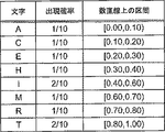
上記した情報源系列内には、A、C、E、H、I、M、R、Tの8種類の文字(シンボル)が現れる。これらの文字に対し、図1の表に示すように、[0.0,1.0)の数直線(確率数直線)上で、文字列における各文字の出現確率に比例した区間長となるようにそれぞれ区間を割り当てる。この文字と数直線上の区間との対応関係を表す図1に示した表が、算術符号化に用いられる確率テーブルとなる。
【0007】
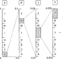
図2は、図1に示した確率テーブルを用いた文字列「ARITHMETIC」の符号化について示す図である。算術符号化においては、確率テーブルに基づいた区間縮小操作を、情報源系列に含まれる各シンボルに対して順次行うことによって、情報源系列を符号化した符号語を生成する。
【0008】
図2に示した例では、まず、符号化対象である文字列「ARITHMETIC」の第1の文字「A」に対して、図1に示した確率テーブルを参照して、数直線上の区間[0,1)を各文字に対応する8個の区間に区分する。そして、それらの区間のうちで、文字「A」に対応する区間[0.0,0.1)へと区間を縮小する。次に、第2の文字「R」に対して、確率テーブルを参照して、区間[0.0,0.1)を8個の区間に区分する。そして、それらの区間のうちで、文字「R」に対応する区間[0.07,0.08)へと区間を縮小する。
【0009】
以下、この区間縮小による符号化操作を各文字に対して順次行っていく。そして、最終的に得られた数直線上の区間[0.0757451536,0.0757451552)において、その区間内にある数値「0.0757451536」が、文字列「ARITHMETIC」を算術符号化した符号語として生成される。
【0010】
図3は、図1に示した確率テーブルを用いた符号語「0.0757451536」の文字列「ARITHMETIC」への復号について示す図である。
【0011】
図3に示した例では、まず、復号対象である符号語「0.0757451536」に対して、図1に示した確率テーブルを参照して、符号語が含まれている区間長0.1の区間[0.0,0.1)を特定する。そして、特定された区間に対応する文字「A」を第1の文字として出力するとともに、(符号語−下限)/(区間長)によって、新たな符号語「0.757451536」を生成する。次に、符号語「0.757451536」に対して、確率テーブルを参照して、符号語が含まれている区間長0.1の区間[0.7,0.8)を特定する。そして、特定された区間に対応する文字「R」を第2の文字として出力するとともに、新たな符号語「0.57451536」を生成する。
【0012】
以下、この復号操作を符号語に対して順次行っていく。そして、算術符号化された符号語「0.0757451536」から、文字列「ARITHMETIC」が復元される。
【0013】
このように、算術符号化を用いた情報源系列の可変長符号化では、情報源系列に含まれるシンボルと数直線上の区間とを対応付けることにより、任意の情報源系列を[0.0,1.0)の数直線上の符号語によって表現することができる。また、シンボルと区間とを対応付ける確率テーブルを各シンボルの出現確率に応じて設定することにより、情報源系列の可変長符号化を効率良く行って、符号化によるデータ圧縮の効率を向上することができる。
【非特許文献1】
VCEG-M10 H.26L Test Model Long Term Number 8 (TML-8) draft0
【発明の開示】
【発明が解決しようとする課題】
【0014】
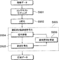
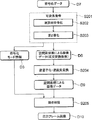
図4は、上述した算術符号化による可変長符号化を用いた画像符号化方法の一例を示すフローチャートである。図4に示した画像符号化方法では、ITU−T H.26L映像符号化方式(VCEG-M10 H.26L Test Model Long Term Number 8 (TML-8) draft0 を参照)で用いられているコンテキストモデリングを用いたCABAC(Context-based Adaptive Binary Arithmetic Coding)と呼ばれる方法によって、画像データの算術符号化を行っている。
【0015】
画像データの符号化においては、まず、符号化対象の画像を所定サイズのブロックに分割し、ブロック毎にイントラフレーム符号化(Intra-Frame Coding、フレーム内符号化)やインターフレーム符号化(Inter-Frame Coding、フレーム間符号化)、DCT等の直交変換などの必要なデータ変換処理を行って、ブロック内にある画像を表す画像データを生成する。そして、その画像データに対して、算術符号化などを用いて可変長符号化を行って、データ圧縮された符号化データが生成される。
【0016】
図4に示した画像符号化方法においては、特に、あらかじめ固定に設定された条件によって符号化を行うのではなく、ブロック毎の画像データを符号化する際に、コンテキストモデリングを行っている(ステップS901、Context Modeling)。コンテキストモデリングを用いた算術符号化では、画像データの符号化に用いる確率テーブルについて、符号化対象のブロックでの画像データに対して適用する確率テーブルが、隣接ブロックでの画像符号化の処理結果などの符号化条件を参照して切り換えて設定される。
【0017】
コンテキストモデリングによる確率テーブルの設定を終了したら、符号化対象の画像データ(例えば複数のDCT係数)を2値化して、伝送すべきデータ系列を生成する(S902、Binarization)。そして、2値化されたデータ系列に対して算術符号化を行って(S903、Adaptive Binary Arithmetic Coding)、符号化データを得る。
【0018】
具体的には、2値化されたデータ系列の各ビットに対し、コンテキストモデリングによって設定された確率テーブルを割り当てて確率評価を行う(S904、Probability Estimation)。そして、割り当てられた確率テーブルを用いてデータ系列を算術符号化し、符号化データである数直線上の符号語を生成する(S905、Arithmetic Coding)。また、算術符号化の処理結果に基づいて、符号化したビットの発生頻度などの情報を確率テーブルへとフィードバックすることによって確率評価を更新し、符号化の傾向を確率テーブルに反映させる(S906、Probability Estimation Update)。
【0019】
コンテキストモデリングを用いた算術符号化による上記の画像符号化方法によれば、符号化条件や処理結果に応じて使用する確率テーブルを切り換えることによって、符号化データでの冗長度を低減することが可能である。
【0020】
一方、画像符号化において上述した動き補償を行う場合、動き補償での補償条件や方法が異なる複数の符号化モードを用意しておき、その中から各画像データに適用する符号化モードを選択して動き補償を行う場合がある。このような場合には、選択された符号化モードを示す符号化モード情報も画像データとともに可変長符号化されて、符号化データに多重化される。したがって、符号化データでの冗長度の低減については、この符号化モード情報についても冗長度の除去を行って、符号化データでのデータ圧縮の効率を向上することが必要となる。
【0021】
本発明は、以上の問題点を解決するためになされたものであり、符号化データに多重化される符号化モード情報に対するデータ圧縮の効率を向上することが可能な画像符号化方法、画像復号方法、画像符号化装置、画像復号装置、及びプログラムを提供することを目的とする。
【課題を解決するための手段】
【0022】
このような目的を達成するために、本発明による画像符号化方法は、フレーム画像を所定サイズのブロックに分割し、ブロック毎に画像データを符号化する符号化方法であって、(1)ブロック内にある画像の画像データをフレーム画像または他のフレーム画像にある他のブロックと比較して動きを検出し、動き補償について用意された複数の符号化モードから画像データに適用する符号化モードを選択して、画像データに対する動き補償を行う動き補償ステップと、(2)所定の2値化テーブルを用いて選択された符号化モードを示す符号化モード情報及び画像データを2値化して2値化パターンを生成するとともに、所定の確率テーブルを用いた算術符号化によって2値化パターンを可変長符号化して、符号化データを生成する符号化ステップとを備え、(3)符号化ステップにおいて、符号化モード情報に対応する2値化パターンに含まれる2値化符号のそれぞれについて、ブロックの隣接ブロックで選択された符号化モードを参照して、適用する確率テーブルを切り換えるとともに、(4)符号化ステップにおいて、複数の符号化モードのそれぞれに対して、スキップモード、インターモード、イントラモードの違い、及び動き補償用ブロックへの区分数の違いに基づいて複雑度を設定しておき、隣接ブロックで選択された符号化モー ドに対応する複雑度を参照して、確率テーブルを切り換えることを特徴とする。
【0023】
同様に、本発明による画像符号化装置は、フレーム画像を所定サイズのブロックに分割し、ブロック毎に画像データを符号化する符号化装置であって、(1)ブロック内にある画像の画像データをフレーム画像または他のフレーム画像にある他のブロックと比較して動きを検出し、動き補償について用意された複数の符号化モードから画像データに適用する符号化モードを選択して、画像データに対する動き補償を行う動き補償手段と、(2)所定の2値化テーブルを用いて選択された符号化モードを示す符号化モード情報及び画像データを2値化して2値化パターンを生成するとともに、所定の確率テーブルを用いた算術符号化によって2値化パターンを可変長符号化して、符号化データを生成する符号化手段とを備え、(3)符号化手段は、符号化モード情報に対応する2値化パターンに含まれる2値化符号のそれぞれについて、ブロックの隣接ブロックで選択された符号化モードを参照して、適用する確率テーブルを切り換えるとともに、(4)符号化手段は、複数の符号化モードのそれぞれに対して、スキップモード、インターモード、イントラモードの違い、及び動き補償用ブロックへの区分数の違いに基づいて複雑度を設定しておき、隣接ブロックで選択された符号化モードに対応する複雑度を参照して、確率テーブルを切り換え
ることを特徴とする。
【0024】
また、本発明による画像符号化プログラムは、上記した画像符号化方法をコンピュータに実行させることを特徴とする。
【0025】
上記した画像符号化方法、装置、及びプログラムにおいては、動き補償での補償条件や方法が異なる複数の符号化モードから適用する符号化モードを選択して動き補償を行った後、動き補償がされた画像データと、動き補償に適用された符号化モードを示す符号化モード情報とを算術符号化し多重化して、データ圧縮された符号化データを生成する。そして、符号化モード情報の算術符号化において、符号化モード情報が2値化された2値化パターンに含まれる2値化符号のそれぞれについて、隣接ブロックでの処理結果を参照しつつ確率テーブルを切り換えて、算術符号化を行うこととしている。
【0026】
これにより、2値化パターンでの2値化符号のそれぞれの符号位置や、隣接ブロックで選択された符号化モードなどが、算術符号化での符号化条件に対して反映される。したがって、符号化モード情報の冗長度を効果的に除去して、符号化データでのデータ圧縮の効率を向上することが可能となる。
【0027】
また、本発明による画像復号方法は、フレーム画像を所定サイズのブロックに分割し、ブロック毎に画像データを符号化した符号化データを復号する復号方法であって、(1)所定の確率テーブルを用いた逆算術符号化によって符号化データを可変長復号して2値化パターンを生成するとともに、所定の2値化テーブルを用いて2値化パターンを逆2値化して、符号化モード情報及びブロック内にある画像の画像データを生成する復号ステップと、(2)動き補償について用意された複数の符号化モードから符号化モード情報が示す選択された符号化モードを適用して、画像データに対する動き補償を行う動き補償ステップとを備え、(3)復号ステップにおいて、符号化モード情報に対応する2値化パターンに含まれる2値化符号のそれぞれについて、ブロックの隣接ブロックで選択された符号化モードを参照して、適用する確率テーブルを切り換えるとともに、(4)復号ステップにおいて、複数の符号化モードのそれぞれに対して、スキップモード、インターモード、イントラモードの違い、及び動き補償用ブロックへの区分数の違いに基づいて複雑度を設定しておき、隣接ブロックで選択された符号化モードに対応する複雑度を参照して、確率テーブルを切り換えることを特徴とする。
【0028】
同様に、本発明による画像復号装置は、フレーム画像を所定サイズのブロックに分割し、ブロック毎に画像データを符号化した符号化データを復号する復号装置であって、(1)所定の確率テーブルを用いた逆算術符号化によって符号化データを可変長復号して2値化パターンを生成するとともに、所定の2値化テーブルを用いて2値化パターンを逆2値化して、符号化モード情報及びブロック内にある画像の画像データを生成する復号手段と、(2)動き補償について用意された複数の符号化モードから符号化モード情報が示す選択された符号化モードを適用して、画像データに対する動き補償を行う動き補償手段とを備え、(3)復号手段は、符号化モード情報に対応する2値化パターンに含まれる2値化符号のそれぞれについて、ブロックの隣接ブロックで選択された符号化モードを参照して、適用する確率テーブルを切り換えるとともに、(4)復号手段は、複数の符号化モードのそれぞれに対して、スキップモード、インターモード、イントラモードの違い、及び動き補償用ブロックへの区分数の違いに基づいて複雑度を設定しておき、隣接ブロックで選択された符号化モードに対応する複雑度を参照して、確率テーブルを切り換えることを特徴とする。
【0029】
また、本発明による画像復号プログラムは、上記した画像復号方法をコンピュータに実行させることを特徴とする。
【0030】
上記した画像復号方法、装置、及びプログラムにおいては、データ圧縮された符号化データを逆算術符号化及び逆2値化することによって符号化モード情報及び画像データを復号した後、符号化モード情報が示す符号化モードを適用して動き補償を行う。そして、符号化データの逆算術符号化において、上述した算術符号化の場合と同様に、符号化モード情報が2値化された2値化パターンに含まれる2値化符号のそれぞれについて、隣接ブロックでの処理結果を参照しつつ確率テーブルを切り換えて、逆算術符号化を行うこととしている。
【0031】
これにより、2値化パターンでの2値化符号のそれぞれの符号位置や、隣接ブロックで選択された符号化モードなどが、逆算術符号化での復号条件に対して反映される。したがって、符号化モード情報の冗長度を効果的に除去して、符号化データでのデータ圧縮の効率が向上された符号化データから、データを好適に復元することが可能となる。
【0032】
また、符号化方法、復号方法、及び符号化装置、復号装置は、複数の符号化モードが、動き補償を行うとともにブロック内にある画像の動き補償用ブロックへの区分方法が互いに異なる2以上の符号化モードを含むことが好ましい。
【0033】
動き補償用ブロックは、符号化対象となっているブロック内を1または複数のブロックに区分して、その区分された動き補償用ブロック毎に動きベクトルの付与を行うためのものである。このような動き補償用ブロックに対し、ブロック区分が異なる2以上の符号化モードを含む上記の複数の符号化モードについて、隣接ブロックで選択された符号化モードを参照して確率テーブルの切り換えを行うことにより、動き補償用ブロックの区分方法を含む動き補償の条件に応じて符号化データでの冗長度を低減させて、そのデータ圧縮の効率をさらに向上することができる。
【0034】
また、複数の符号化モードは、動き補償に使用する参照フレームと同位置の画像をコピーするスキップモードを含むことが好ましい。ただし、このスキップモードについては、複数の符号化モードにスキップモードが含まれない構成としても良い。
【0035】
また、画像伝送システムとしては、フレーム画像を所定サイズのブロックに分割し、ブロック毎に画像データを符号化した符号化データによってフレーム画像を伝送する画像伝送システムであって、(1)フレーム画像から符号化データを生成して出力する上記した画像符号化装置と、(2)画像符号化装置からの符号化データを入力してフレーム画像を復元する上記した画像復号装置とを備えることが好ましい。
【0036】
このような画像伝送システムによれば、符号化データに多重化される符号化モード情報に対するデータ圧縮の効率が向上された符号化データを用いて、効率的に画像を伝送することができる。
【発明の効果】
【0037】
本発明による画像符号化方法、画像復号方法、画像符号化装置、画像復号装置、及びプログラムは、符号化データに多重化される符号化モード情報に対するデータ圧縮の効率を向上することが可能な方法及び装置等として利用可能である。
【発明を実施するための最良の形態】
【0038】
以下、図面とともに本発明による画像符号化方法、画像復号方法、画像符号化装置、画像復号装置、及びプログラムの好適な実施形態について詳細に説明する。なお、図面の説明においては同一要素には同一符号を付し、重複する説明を省略する。また、図面の寸法比率は、説明のものと必ずしも一致していない。
【0039】
まず、画像符号化方法及び画像符号化装置について説明する。
【0040】
図5は、本発明による画像符号化方法の一実施形態を概略的に示すフローチャートである。本符号化方法は、動画像などでのフレーム画像である入力フレーム画像D1に対して所定の変換処理操作及び符号化処理操作を行って、モバイル映像伝送システムなどの画像伝送システムにおいて伝送可能なデータ圧縮された符号化データD7を生成する画像符号化方法である。
【0041】
図5に示した画像符号化方法においては、まず、入力フレーム画像D1に対して所定のデータ処理操作を行って画像データを変換し、空間座標によって表された画像データ(空間画像データ)D5とする(ステップS101、動き補償ステップ)。ここでのデータ処理操作としては、具体的には、動画像でのフレーム画像に対してインターフレーム符号化(フレーム間符号化)を行う場合の動き補償(MC:Motion Compensation)フレーム間予測が行われる。この動き補償は、フレーム画像を所定サイズ(所定の画素数)で分割したブロック毎に、ブロック内にある画像の画像データに対して行われる。
【0042】
ここで、本実施形態の画像符号化方法においては、このフレーム画像の動き補償について、動き補償での補償条件や方法が異なる複数の符号化モードが用意されている。動き補償フレーム間予測では、ブロック内にある画像の画像データをフレーム画像または他のフレーム画像にある他のブロックと比較して、画像の動きを検出し、その検出結果に基づいて、用意された複数の符号化モードから画像データに適用する符号化モードを選択する。
【0043】
そして、選択された符号化モードを適用して画像データの動き補償を行って、動きベクトルと、差分フレーム画像である空間画像データD5とを生成する。また、選択された符号化モードを示す情報は、符号化モード情報D3となる。
【0044】
次に、空間画像データD5に対して直交変換操作を行って、空間周波数によって表された画像データ(周波数画像データ)である複数の直交変換係数D6を生成する(S102、直交変換ステップ)。この直交変換は、フレーム画像を分割したブロック毎に行われ、入力フレーム画像D1に含まれる各ブロックに対して、それぞれ直交変換係数D6が得られる。また、この直交変換係数に対して、必要に応じて量子化操作がさらに行われ、符号化対象となる直交変換係数(量子化係数)が生成される。
【0045】
続いて、複数の直交変換係数D6に対して算術符号化を用いて可変長符号化を行い、圧縮データである符号化データD7を生成する(S103、符号化ステップ)。また、動き補償に対して選択された符号化モードを示す符号化モード情報D3も、直交変換係数D6とともに算術符号化を用いて可変長符号化され、符号化データD7に多重化される。
【0046】
具体的には、まず、符号化モード情報D3と、画像データである直交変換係数D6とがそれぞれ所定の2値化テーブルを用いて2値化されて、2値化パターンが生成される(S104、2値化ステップ)。そして、符号化モード情報D3と直交変換係数D6とに対応する2値化パターンそれぞれに対して、適用する確率テーブルが所定の確率テーブルに設定され、その確率テーブルを用いて2値化パターンが算術符号化されて(S105、算術符号化ステップ)、符号化データD7が生成される。
【0047】
ここで、本実施形態の画像符号化方法においては、2値化パターンに対して算術符号化を行う際に、符号化モード情報に対応する2値化パターンに含まれる2値化符号のそれぞれについて、符号化対象のブロックの隣接ブロックで選択された符号化モードを参照して、各2値化符号に適用する確率テーブルを切り換えている。
【0048】
本実施形態による画像符号化方法の効果について説明する。
【0049】
図5に示した画像符号化方法においては、動き補償での補償条件や方法が異なる複数の符号化モードから適用する符号化モードを選択して動き補償を行った後、動き補償がされた画像データD6と、動き補償に用いられた符号化モードを示す符号化モード情報D3とを算術符号化し多重化して、データ圧縮された符号化データD7を生成する。そして、符号化モード情報D3の算術符号化において、符号化モード情報D3が2値化された2値化パターンに含まれる2値化符号のそれぞれについて、隣接ブロックでの処理結果を参照しつつ確率テーブルを切り換えて、算術符号化を行うこととしている。
【0050】
このように、符号化モード情報に対応する2値化パターンでの2値化符号のそれぞれに対して確率テーブルを適宜切り換えるコンテキストモデリングを行うことにより、2値化パターンでの2値化符号のそれぞれの符号位置や、隣接ブロックで選択された符号化モードなどが、算術符号化での符号化条件に対して好適に反映される。したがって、符号化モード情報D3の冗長度を効果的に除去して、符号化データD7でのデータ圧縮の効率を向上することが可能となる。
【0051】
また、適用する符号化モードを選択するために用意される複数の符号化モードについては、動き補償を行うとともにブロック内にある画像の動き補償用ブロックへの区分方法が互いに異なる2以上の符号化モードを含むことが好ましい。
【0052】
動き補償用ブロックは、符号化対象となっているブロック内を1または複数のブロックに区分して、その区分された動き補償用ブロック毎に動きベクトルの付与を行うためのものである。このような動き補償用ブロックに対し、ブロック区分が異なる2以上の符号化モードを含む上記の複数の符号化モードについて、隣接ブロックで選択された符号化モードを参照して確率テーブルの切り換えを行うことにより、動き補償用ブロックの区分方法を含む動き補償の条件に応じて符号化データでの冗長度を低減させて、そのデータ圧縮の効率をさらに向上することができる。
【0053】
また、複数の符号化モードは、動き補償に使用する参照フレームと同位置の画像をコピーするスキップモードを含むことが好ましい。ただし、このスキップモードについては、複数の符号化モードにスキップモードが含まれない構成としても良い。なお、具体的な符号化モードや、確率テーブルの切り換え方法等については、詳しく後述する。
【0054】
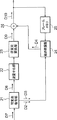
図6は、本発明による画像符号化装置の一実施形態の構成を示すブロック図である。以下、図6に示した画像符号化装置を参照しつつ、図5に示した画像符号化方法についてさらに説明する。なお、以下においては、符号化対象として画像符号化装置に入力される入力フレーム画像D1について、時系列のフレーム画像からなる動画像を想定している。
【0055】
符号化対象として入力された入力フレーム画像D1は、まず、16画素×16ラインのサイズで正方形の画像ブロックへと分割される。この画像ブロックは、動き補償などのデータ処理の単位となる画像ブロックであり、マクロブロックと呼ばれる。なお、後述するDCT(直交変換)では、例えばH.26L符号化方式では、4画素×4ラインのサイズのDCTブロックが用いられる。この場合、1個のマクロブロックは、DCTにおいて、16個の輝度(Luma)ブロックと、8個の色差(Chroma)ブロックとを有する。画像符号化はこれらのブロック毎に行われる。
【0056】
フレーム画像D1は、動き検出部11及び動き補償部12からなる動き補償手段へと入力される。まず、フレーム画像D1は動き検出部11に入力され、マクロブロック毎に画像の動きが検出される。動き検出部11は、動きを検出しようとするマクロブロックでの画像データと、入力フレーム画像または他のフレーム画像にある他のマクロブロックでの画像データとを比較して、画像の動きを示す動きベクトルD2を検出する。
【0057】
具体的には、動き検出部11では、符号化済のフレーム画像としてフレームメモリ20に格納されている局所復号画像D8内の所定の画像領域を参照して、現在の符号化対象となっている入力フレーム画像D1のマクロブロックと類似するパターンを見つけ出す。そして、その類似パターンとマクロブロックとの間の空間的な移動量によって、動きベクトルD2を決定する。
【0058】
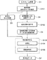
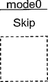
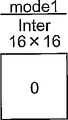
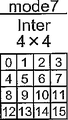
また、このとき、動き補償について用意された複数の符号化モードから、マクロブロックでの動き補償に用いられる符号化モードが選択される。図7A〜図7Jは、動き補償について用意される符号化モードの一例を示す模式図である。この図7A〜図7Jに例示した複数の符号化モードでは、1個のスキップ(Skip)モード0と、7個のインターモード1〜7と、2個のイントラモード8、9との10個の符号化モードが、動き補償に対して用意されている。
【0059】
このうち、スキップモード0は、画像の動きが検出されず、動き補償に使用する参照フレームと同位置の画像をコピーするモードである。
【0060】
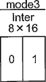
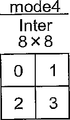
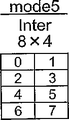
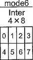
また、インターモード1〜7は、それぞれ異なる動き補償用ブロックへのブロック区分を用いてインターフレーム符号化(フレーム間符号化)を行う場合のモードである。それぞれでの動き補償用ブロックについては、図7B〜図7Hに示すように、モード1では、16×16のサイズで1個のブロックが用いられる。モード2では、16×8のサイズで2個のブロックが用いられる。モード3では、8×16のサイズで2個のブロックが用いられる。モード4では、8×8のサイズで4個のブロックが用いられる。モード5では、8×4のサイズで8個のブロックが用いられる。モード6では、4×8のサイズで8個のブロックが用いられる。モード7では、4×4のサイズで16個のブロックが用いられる。
【0061】
上記した動きベクトルD2は、選択されたインターモードにおける区分された動き補償用ブロック毎に付与され、したがって、各マクロブロックに対して、区分されたブロックの個数分の動きベクトルD2が付与される。なお、各動き補償用ブロックへの動きベクトルD2の付与の順序については、例えば、図7A〜図7J中の各符号化モードにおいて、ブロック内の数字によって示した順序で行われる。
【0062】
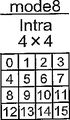
また、イントラモード8、9は、それぞれ異なるブロック区分を用いてイントラフレーム符号化(フレーム内符号化)を行う場合のモードである。それぞれでのブロックについては、図7I、図7Jに示すように、モード8では、4×4のサイズで16個のブロックが用いられる。モード9では、16×16のサイズで1個のブロックが用いられる。
【0063】
符号化モードが選択され、各動き補償用ブロックに対して動きベクトルD2が求められたら、動き補償部12において、動き検出部11からの動きベクトルD2と、フレームメモリ20からの局所復号画像D8とを用いて、動き予測画像を生成する。フレーム画像D1に含まれる全てのマクロブロックについて動きベクトルD2を決定して動き予測画像を生成することにより、入力フレーム画像D1に対する予測フレーム画像D4が得られる。
【0064】
続いて、減算器13において、入力フレーム画像D1と予測フレーム画像D4との間の差分(予測残差)フレーム画像D5が生成される。また、予測フレーム画像D4が作成されていない場合には、入力フレーム画像D1がそのままフレーム画像D5とされる。この空間画像データであるフレーム画像D5が、以後の直交変換及び算術符号化の対象となる。
【0065】
差分フレーム画像D5の画像データは、直交変換部(直交変換手段)14へと入力される。直交変換部14では、差分フレーム画像D5に対して、マクロブロックに含まれる直交変換ブロック(例えば16個の輝度ブロックと8個の色差ブロック)毎に直交変換が行われて、周波数画像データである直交変換係数が生成される。また、この直交変換係数は、量子化部15において所定の量子化パラメータによって量子化されて、算術符号化の対象の画像データとなる最終的な直交変換係数(量子化係数)D6が得られる。
【0066】
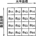
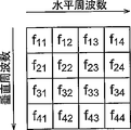
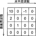
図8A及び図8Bは、画像データの直交変換について示す図である。フレーム画像D5内にある直交変換用に分割された各ブロックの画像データは空間画像データであり、図8Aに4×4の画像成分によって例示するように、水平座標と垂直座標とで規定される4×4の空間画像成分a11〜a44によって表される。直交変換部14は、この空間画像データを所定の変換方法で直交変換することによって、図8Bに示す画像データへと変換する。この画像データは周波数画像データであり、水平周波数と垂直周波数とで規定される4×4の周波数画像成分である直交変換係数f11〜f44によって表される。
【0067】
具体的な直交変換としては、例えば、離散コサイン変換(DCT:Discrete Cosine Transform)を適用することができる。DCTは、フーリエ変換のコサインの項を用いる直交変換であり、画像符号化において多く用いられている。空間画像データに対してDCTを行うことにより、周波数画像データであるDCT係数f11〜f44が生成される。なお、DCTにおいては、例えばH.26L符号化方式では、直交変換用のブロックとして、図8A及び図8Bに示したように4×4のDCTブロックが用いられる。
【0068】
直交変換部14及び量子化部15によって生成された直交変換係数D6は、可変長符号化部(符号化手段)16において、所定の確率テーブルを用いた算術符号化によって可変長符号化される。これにより、入力フレーム画像D1の圧縮データである符号化データD7が生成される。
【0069】
また、可変長符号化部16には、直交変換係数D6に加えて、動き検出部11によって検出された動きベクトルD2と、動き検出部11において選択された符号化モードを示す符号化モード情報D3とが入力されている。これらの動きベクトルD2及び符号化モード情報D3は、可変長符号化部16において、直交変換係数D6と同様に、所定の確率テーブルを用いた算術符号化によって可変長符号化されて、符号化データD7に多重化される。
【0070】
ここで、可変長符号化部16において算術符号化に用いられる確率テーブルの設定については、図5に示した画像符号化方法に関して上述した通りである。動きベクトルD2及び符号化モード情報D3の算術符号化においては、通常は、直交変換係数D6の算術符号化とは異なる確率テーブルが用いられ、符号化モード情報D3に適用する確率テーブルについては、上述のように隣接ブロックでの処理結果を参照しての切り換えが行われる。また、直交変換係数D6の算術符号化においても、輝度ブロックの算術符号化と色差ブロックの算術符号化とで、異なる確率テーブルを用いても良い。
【0071】
また、直交変換部14及び量子化部15によって生成された直交変換係数D6は、本画像符号化装置内において、逆量子化部17及び逆直交変換部18によって復号される。そして、復号された画像データと予測フレーム画像D4とが加算器19において加算されて、局所復号画像D8が生成される。この局所復号画像D8はフレームメモリ20に格納されて、他のフレーム画像の動き補償に利用される。
【0072】
次に、画像復号方法及び画像復号装置について説明する。
【0073】
図9は、本発明による画像復号方法の一実施形態を概略的に示すフローチャートである。本復号方法は、図5に示した画像符号化方法によって生成された符号化データD7に対して所定の復号処理操作及び変換処理操作を行って、入力フレーム画像D1に対応する画像として出力フレーム画像D10を復元する画像復号方法である。
【0074】
図9に示した画像復号方法においては、まず、符号化データD7に対して逆算術符号化を用いて可変長復号を行い、複数の直交変換係数(量子化係数)D6を生成する(S201、復号ステップ)。また、動き補償に対して選択された符号化モードを示す符号化モード情報D3も、直交変換係数D6とともに逆算術符号化を用いて符号化データD7から復号される。
【0075】
具体的には、まず、符号化データD7に対して適用する確率テーブルが所定の確率テーブルに設定され、その確率テーブルを用いて符号化データD7が逆算術符号化されて(S202、逆算術符号化ステップ)、符号化モード情報D3と直交変換係数D6とに対応する2値化パターンがそれぞれ生成される。そして、符号化モード情報D3と直交変換係数D6とに対応する2値化パターンが、それぞれ所定の2値化テーブルを用いて逆2値化されて、符号化データ情報D3及び直交変換係数D6が生成される(S203、逆2値化ステップ)。
【0076】
ここで、本実施形態の画像復号方法においては、符号化データD7に対して逆算術符号化を行う際に、符号化モード情報に対応する2値化パターンに含まれる2値化符号のそれぞれについて、符号化対象のブロックの隣接ブロックで選択された符号化モードを参照して、各2値化符号に適用する確率テーブルを切り換えている。
【0077】
次に、複数の直交変換係数D6に対して逆量子化操作及び逆直交変換操作を順次行って、空間画像データD9を生成する(S204、逆直交変換ステップ)。そして、空間画像データD9に対して符号化モード情報D3が示す符号化モードを適用して動き補償を行い、出力フレーム画像D10を復元する(S205、動き補償ステップ)。
【0078】
本実施形態による画像復号方法の効果について説明する。
【0079】
図9に示した画像復号方法においては、データ圧縮された符号化データD7を逆算術符号化及び逆2値化することによって符号化モード情報D3及び画像データD6を復号した後、符号化モード情報D3が示す符号化モードを適用して動き補償を行う。そして、符号化データD7の逆算術符号化において、上述した算術符号化の場合と同様に、符号化モード情報D3が2値化された2値化パターンに含まれる2値化符号のそれぞれについて、隣接ブロックでの処理結果を参照しつつ確率テーブルを切り換えて、逆算術符号化を行うこととしている。
【0080】
このように、符号化モード情報に対応する2値化パターンでの2値化符号のそれぞれに対して確率テーブルを適宜切り換えるコンテキストモデリングを行うことにより、2値化パターンでの2値化符号のそれぞれの符号位置や、隣接ブロックで選択された符号化モードなどが、逆算術符号化での復号条件に対して好適に反映される。したがって、符号化モード情報D3の冗長度を効果的に除去して、データ圧縮の効率が向上された符号化データD7から、データを好適に復元することが可能となる。
【0081】
図10は、本発明による画像復号装置の一実施形態の構成を示すブロック図である。
【0082】
復号対象として入力された符号化データD7は可変長復号部(復号手段)21に入力されて所定の確率テーブルを用いた逆算術符号化によって可変長復号され、複数の直交変換係数D6等が生成される。可変長復号部21は、データ圧縮された符号化データD7について、フレーム画像の先頭を示す同期ワードを検出し、以後、マクロブロック毎に符号化データD7に含まれている各データを復号して、周波数画像データである直交変換係数D6、動きベクトルD2、及び符号化モード情報D3等を生成する。なお、算術符号化に用いる確率テーブルは、上述のように適宜切り換えられる。
【0083】
可変長復号部21において復号された直交変換係数D6は、逆量子化部22及び逆直交変換部(逆直交変換手段)23によって逆量子化、逆直交変換される。これにより、空間画像データである復元差分フレーム画像D9が生成される。この復元差分フレーム画像D9は、符号化前の差分フレーム画像D5に対応したフレーム画像である。
【0084】
一方、動きベクトルD2及び符号化モード情報D3は、動き補償部24へと入力される。動き補償部24では、符号化モード情報D3が示す符号化モードによって画像の動き補償が行われ、可変長復号部21からの動きベクトルD2と、フレームメモリ25に格納されている他のフレーム画像とを用いて、予測フレーム画像D4が生成される。そして、加算器26において、復元差分フレーム画像D9と予測フレーム画像D4とが加算されて、復元されたフレーム画像が出力フレーム画像D10として出力される。
【0085】
ここで、上記した画像符号化装置において実行される画像符号化方法に対応する処理は、画像符号化をコンピュータに実行させるための画像符号化プログラムによって実現可能である。また、画像復号装置において実行させる画像復号方法に対応する処理は、画像復号をコンピュータに実行させるための画像復号プログラムによって実現可能である。
【0086】
例えば、画像符号化装置は、画像符号化の処理動作に必要な各ソフトウェアプログラムなどが記憶させるROMと、プログラム実行中に一時的にデータが記憶されるRAMとが接続されたCPUによって構成することができる。このような構成において、CPUによって所定の画像符号化プログラムを実行することにより、画像符号化装置を実現することができる。
【0087】
同様に、画像復号装置は、画像復号の処理動作に必要な各ソフトウェアプログラムなどが記憶されるROMと、プログラム実行中に一時的にデータが記憶されるRAMとが接続されたCPUによって構成することができる。このような構成において、CPUによって所定の画像復号プログラムを実行することにより、画像復号装置を実現することができる。
【0088】
また、画像符号化または画像復号のための各処理をCPUに実行させるための上記したプログラムは、コンピュータ読取可能な記録媒体に記録して頒布することが可能である。このような記録媒体には、例えば、ハードディスク及びフレキシブルディスクなどの磁気媒体、CD−ROM及びDVD−ROMなどの光学媒体、フロプティカルディスクなどの磁気光学媒体、あるいは、プログラム命令を実行または格納するように特別に配置された、例えばRAM、ROM、及び半導体不揮発性メモリなどのハードウェアデバイスなどが含まれる。
【0089】
また、画像符号化または画像復号をコンピュータに実行させるための上記したプログラムは、搬送波に包含されるコンピュータデータ信号とすることが可能である。これにより、画像符号化プログラムまたは画像復号プログラムを、有線または無線の搬送路等を介して搬送することができる。
【0090】
以下、図5、図6に示した画像符号化方法及び画像符号化装置における画像データ及び符号化モード情報の算術符号化(可変長符号化)の手順、及びその好適な符号化条件について、ITU−T H.26L符号化方式を例として、具体例を示しつつ説明する。なお、以下に説明する符号化方法及び符号化条件については、図9、図10に示した画像復号方法及び画像復号装置に対しても同様に適用することが可能である。また、具体的な符号化方式については、上記したH.26L符号化方式には限定されない。
【0091】
まず、図11A〜図11Dを参照して、画像データである直交変換係数の算術符号化の手順について説明しておく。ここでは、空間画像データを周波数画像データへと変換する直交変換としては、DCTを想定する。図11Aは、図8Bに示した4×4のDCT係数(量子化係数)f11〜f44の具体的な一数値例を示している。画像符号化装置の可変長符号化部では、このようなDCT係数に対して所定の処理手順で算術符号化を行って、符号化データを生成する。
【0092】
係数fijの添字の値i、jが対応する垂直周波数、水平周波数をそれぞれ表しているDCT係数f11〜f44においては、空間画像データでの画像成分a11〜a44(図8A参照)とは異なり、各DCT係数が、その係数値の大きさなどについて、対応する空間周波数の値に依存したデータ特性を有している。一般に、自然画像においては、低周波数域で大きい直交変換の係数値が得られ、高周波数になるにしたがって係数値が小さくなる。
【0093】
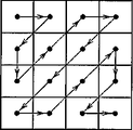
DCT係数の算術符号化の処理手順においては、まず、2次元データであるDCT係数f11〜f44が、図11Bに示すジグザグ・スキャンによって、1次元データへと変換される。このジグザグ・スキャンでは、スキャン後の1次元データが低周波数域から高周波数域へと移行していくデータ列となるように、DCT係数がスキャンされる。これにより、低周波数域から高周波数域へとDCT係数が並ぶ、図11Cに示す1次元データが得られる。
【0094】
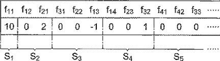
このDCT係数の1次元データは、そのデータ量を低減するため、さらに、図11Dに示すLevel(レベル)及びRun(ラン)からなるデータへと変換される。ここで、Levelは、複数のDCT係数のうちで0でない係数値を持つDCT係数での係数レベルを示す。また、Runは、0でないDCT係数の直前にある係数値が0のデータの数であるランレングスを示す。
【0095】
例えば、図11Aに示したDCT係数のデータ例では、図11Cに示すように、16個のDCT係数f11〜f44が、0でない係数値を持つDCT係数の出現位置に基づいて、係数f11からなる係数群s1、係数f12、f21からなる係数群s2、係数f31〜f13からなる係数群s3、係数f14〜f32からなる係数群s4、及び係数f41〜f44からなる係数群s5へと区分される。
【0096】
そして、これらの係数群s1〜s5に対して、図11Dに示すように、それぞれLevel値及びRun値が求められる。具体的には、係数群s1では、Level値がf11=10、Run値が0である。また、係数群s2では、Level値がf21=2、Run値が1である。また、係数群s3では、Level値がf13=−1、Run値が2である。また、係数群s4では、Level値がf32=1、Run値が2である。
【0097】
また、最後の係数群s5は、全ての係数f41〜f44の係数値が0となっている係数群であり、図11Aに示したDCT係数における有効なデータの終端(EOB:End of Block)となっている。したがって、この係数群s5では、EOB符号を意味する0をLevel値とする。
【0098】
図11Dに示したLevel及びRunからなるデータは、所定の2値化テーブルを用いて2値化され、算術符号化の対象となる2値化パターンが作成される。各Level及びRunのデータがそれぞれ2値化されたら、それらのデータをs1のLevel、s1のRun、s2のLevel、s2のRun、…、s5のLevelの順で、所定の確率テーブルを用いて算術符号化して、図11Aの直交変換係数に対応する符号化データである符号語を生成する。
【0099】
次に、図12〜図15を参照して、動き補償について選択された符号化データを示す符号化データ情報の算術符号化の手順について説明する。ここでは、動き補償について用意される複数の符号化モードとしては、図7A〜図7Jに示した10個の符号化モード0〜9、すなわち1個のスキップモード0、7個のインターモード1〜7、及び2個のイントラモード8、9を想定する。
【0100】
ここで、図7A〜図7Jに示した複数の符号化モードは、動き補償に使用する参照フレームと同位置の画像をコピーするスキップモードと、動き補償を行うとともにブロック内にある画像の動き補償用ブロックへの区分方法が互いに異なる2以上の符号化モードとを含んで設定されている。動き補償用ブロックは、上記したように、符号化対象となっているブロック内を1または複数のブロックに区分して、その区分された動き補償用ブロック毎に動きベクトルの付与を行うためのものである。
【0101】
このような動き補償用ブロックに対し、ブロック区分が異なる2以上の符号化モードを含む図7A〜図7Jに示した複数の符号化モードについて、隣接ブロックで選択された符号化モードを参照して確率テーブルの切り換えを行うことにより、動き補償用ブロックの区分方法を含む動き補償の条件に応じて符号化データでの冗長度を低減させて、そのデータ圧縮の効率をさらに向上することができる。なお、スキップモードについては不要であれば設けない構成としても良い。
【0102】
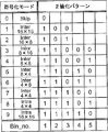
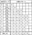
図7A〜図7Jに示した10個の符号化モード0〜9で、どの符号化モードが選択されたかを特定するための符号化モード情報の可変長符号化では、まず、所定の2値化テーブルを用いて符号化モード情報が2値化され、算術符号化の直接の対象となる2値化パターンが作成される。図12は、図7A〜図7Jに示した符号化モードを示す符号化モード情報の2値化に用いられる2値化テーブルの一例を示す表である。
【0103】
符号化モード情報が2値化されたら、得られた2値化パターンを所定の確率テーブルを用いて算術符号化して、符号化モード情報に対応する符号化データである符号語を生成する。ここで、符号化モード情報の算術符号化に適用される確率テーブルについては、2値化パターンに含まれる2値化符号それぞれの2値化パターン内での符号位置(図12に示すBin_no.)毎に、異なる確率テーブルを用いても良い。あるいは、各符号位置で共通の確率テーブルを用いても良い。
【0104】
さらに、図5、図6に示した画像符号化方法及び画像符号化装置においては、上述したように、この符号化モード情報の算術符号化において、符号化モード情報の2値化パターンに含まれる2値化符号のそれぞれについて、符号化対象のブロックの隣接ブロックで、複数の符号化モードのどの符号化モードが選択されたかを参照して確率テーブルを切り換えて、算術符号化を行っている。
【0105】
ここで、図7A〜図7Jに示した10個の符号化モードのうちで、動き補償用ブロックの区分方法が異なる7個のインターモード1〜7について考えると、これらのインターモードからどの符号化モードが選択されるかは、検出される画像の動きの度合に依存する。
【0106】
例えば、フレーム画像中で背景部分などの動きが単純な画像領域では、全体として動きベクトルを付与すれば充分に動き補償が可能である。したがってこの場合には、16×16のモード1などのブロック区分数が少ないインターモードが選択される。一方、動きが複雑で激しい画像領域では、動きベクトルを細かく付与して動き補償を行う必要がある。したがってこの場合には、4×4のモード7などのブロック区分数が多いインターモード、あるいはイントラモードが選択される。
【0107】
そして、このような画像中での動きが単純または複雑な画像領域は、複数のマクロブロックにわたって広がる画像領域となっていることが多い。このため、あるブロックで動き補償用ブロックの区分数が少ないインターモードが選択されていれば、隣接するブロックでも同様に区分数が少ないインターモードが選択される可能性が高い。これは、区分数が多い符号化モードについても同様である。すなわち、隣接するブロック同士では、選択される符号化モードに一定の相関が存在する。
【0108】
この符号化モード選択の特性を利用し、隣接ブロックでの符号化モードの選択結果を参照して符号化モード情報に適用する確率テーブルを切り換えて算術符号化を行えば、符号化モード情報の冗長度を効果的に除去することができ、符号化データでのデータ圧縮の効率を向上することができる。
【0109】
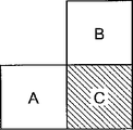
この確率テーブルの切り換えについては、具体的には、例えば図13に示すように、符号化対象のブロックCに対して、左側に位置する隣接ブロックA及び上側に位置する隣接ブロックBを考え、これらの隣接ブロックA、Bでの処理結果を参照する方法がある。
【0110】
すなわち、隣接ブロックA、Bにおいて選択された符号化モードを参照して、ブロックCでの符号化モード情報の2値化パターンに含まれる2値化符号のそれぞれに対して適用する確率テーブルを切り換える。このようなコンテキストモデリングによる確率テーブルの切り換えは、例えば、図4に示したコンテキストモデリングを用いた符号化方法(CABAC)などによって行うことができる。
【0111】
また、隣接ブロックでの処理結果の参照方法としては、隣接ブロックで選択された符号化モードを直接に参照しても良い。
【0112】
あるいは、動き補償について用意されている複数の符号化モードのそれぞれに対してあらかじめ複雑度を設定しておき、隣接ブロックで選択された符号化モードに対応する複雑度を参照して、確率テーブルを切り換える方法を用いることができる。このように、複数の符号化モードのそれぞれに対して複雑度を設定しておくことにより、隣接ブロックで選択された符号化モードなどの条件を、算術符号化での符号化条件に対して好適に反映させることができる。
【0113】
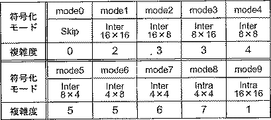
図14は、図7A〜図7Jに示した複数の符号化モードのそれぞれに対して設定される複雑度の例を示す表である。図14に示した設定例では、スキップモード/インターモード/イントラモードの違い、及び動き補償用ブロックへの区分数の違いに基づいて、数字が大きいほど複雑度が高くなるように各符号化モードに対する複雑度0〜7を設定している。
【0114】
具体的には、スキップモード0の複雑度が0、区分数1のイントラモード9での複雑度が1、区分数1のインターモード1での複雑度が2、区分数2のインターモード2及び3での複雑度が3、区分数4のインターモード4での複雑度が4、区分数8のインターモード5及び6での複雑度が5、区分数16のインターモード7での複雑度が6、区分数16のイントラモード8での複雑度が7に設定されている。
【0115】
ただし、各符号化モードに対する複雑度の設定については、図14に示した以外の設定を用いることも可能である。例えば、図14に示した例では、横方向にブロック区分を行っているモード2(図7C)と、縦方向にブロック区分を行っているモード3(図7D)とに対して、同一の複雑度を設定している。これに対して、区分方向の違いによって異なる複雑度を設定しても良い。これは、モード2、3以外の各モードについても同様である。また、区分方向以外の条件を参照して複雑度を設定しても良い。
【0116】
図15は、隣接ブロックで選択された符号化モードに対応する複雑度と、符号化対象のブロックで選択される符号化モードとの相関を示すグラフである。このグラフにおいて、横軸は、符号化対象のブロックで選択される符号化モードを示している。ただし、ここでは、インターモードの符号化モード1〜7について示している。また、縦軸は、各符号化モードが選択される確率を示している。
【0117】
具体的には、図15中に示されている各グラフでは、図13に示した隣接ブロックの参照方法において、隣接ブロックA、Bでそれぞれ選択された符号化モードの複雑度の平均値について着目している。そして、隣接ブロックA、Bでの複雑度の平均値が図14に示した複雑度の設定において0、1、2、3、4、5であった場合について、それぞれブロックCで選択される符号化モードの選択確率のグラフを示している。
【0118】
図15のグラフに示すように、隣接ブロックで選択された符号化モードの複雑度が0〜2で低い場合には、符号化対象のブロックにおいて区分数が少ないインターモード1が選択される確率が大きくなっている。これに対して、隣接ブロックで選択された符号化モードの複雑度が3〜5で高い場合には、符号化対象のブロックにおいて区分数が少ないインターモード1が選択される確率は小さい。隣接するブロック同士での、選択される符号化モードのこのような相関を利用すれば、符号化モード情報の2値化パターンに含まれる各2値化符号に対する確率テーブルを切り換えることにより、符号化モード情報の冗長度を除去することが可能である。
【0119】
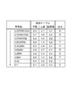
図16は、上記した符号化モード情報の2値化符号に対する確率テーブルの切り換えによる符号量の低減効果について示す表である。この表では、従来のH.26L符号化方式のCABACを用いて画像を符号化した場合の符号量、符号化モード情報の2値化パターンでの各2値化符号に対する確率テーブルを切り換える本発明の方法を用いて画像を符号化した場合の符号量、及び確率テーブルを切り換える方法を用いたことによる符号量の低減率を示している。
【0120】
ここで、符号量の低減率をみるための符号化対象の画像データ、及び画像符号化に用いる量子化パラメータQPについては、(a)テスト画像「Foreman」でQP=24、(b)テスト画像「Stefan」でQP=24、及び(c)テスト画像「Stefan」でQP=16、の3つの条件で画像符号化を行った。
【0121】
図16の表に示すように、3つの条件での画像符号化のすべてにおいて、確率テーブルの切り換えによる符号量の低減効果が得られている。
【0122】
なお、符号化モード情報の2値化パターンに含まれる各2値化符号に対する確率テーブルの切り換えについては、上述した画像符号化方法及び装置では、例えばBin_no.1(符号位置1、図12参照)の2値化符号のみについて確率テーブルの切り換えを行うのではなく、2値化パターンに含まれる2値化符号のそれぞれについて確率テーブルを切り換えている。
【0123】
例えば、図12に示した2値化テーブルでは、選択された符号化モードによって2値化パターンのパターン長が異なっている。これに対して、2値化符号のそれぞれについて確率テーブルを切り換えることにより、複数の符号化モードのいずれが選択された場合であっても、その符号化モードでのデータ圧縮の効率を向上することができる。ただし、この確率テーブルの切り換えについては、複数の2値化符号の全体として切り換えても良く、あるいは、2値化符号のそれぞれで別個に切り換えても良い。
【0124】
ここで、2値化符号に適用する確率テーブルの切り換えについては、2値化符号の2値化パターンでの符号位置(Bin_no.)と、その2値化符号によって区別される符号化モードとの相関を考慮して、確率テーブルを切り換えることが好ましい。このように、2値化パターンに含まれる2値化符号の、それぞれの符号位置に応じた符号化モードとの対応関係を考慮して確率テーブルを切り換えることにより、隣接ブロックで選択された符号化モードなどの条件を、算術符号化での符号化条件に対して好適に反映させることができる。
【0125】
このような確率テーブルの切り換え方法の具体例について、図17を参照して説明する。図17は、図7A〜図7Jに示した符号化モードを示す符号化モード情報の2値化に用いられる2値化テーブルの他の例を示す表である。
【0126】
図17に示した2値化テーブルにおける2値化パターンでは、その1ビット目であるBin_no.1の2値化符号は、符号化モードがスキップモード0か、それ以外のモード1〜9かを示すビットとなっている。したがって、このビットに対しては、例えば、隣接ブロックA、Bがスキップモード0であるかどうかなどによって3つの確率テーブルを切り換える。
【0127】
また、2ビット目であるBin_no.2の2値化符号は、1ビット目が「1」であった場合に、符号化モードが16×16のインターモード1か、それ以外のモード2〜9かを示すビットとなっている。したがって、このビットに対しては、隣接ブロックがスキップモード0または16×16のインターモード1か、それ以外かによって確率テーブルを切り換える。なお、16×16のインターモード1は、背景などの比較的動きの単純な画像部分や、動きの少ない画像部分に多く発生するため、スキップモード0との相関性が高い。
【0128】
具体的には、例えば、隣接マクロブロックA、Bでのモードについて、スキップモード0、16×16のインターモード1、画面外であれば0、それ以外であれば1としたときのA+Bの大きさによって3つの確率テーブルを切り換える。A+B=0のときには0となる確率が大きい確率テーブルとし、A+B=2のときには1となる確率が大きい確率テーブルとする。なお、このような方法は、3ビット目以降についても同様に適用可能である。
【0129】
3ビット目であるBin_no.3の2値化符号は、2ビット目が「1」であった場合に、符号化モードが16×8のインターモード2または8×16のインターモード3か、それ以外のモード4〜9かを示すビットとなっている。したがって、このビットに対しては、1ビット目、2ビット目とは異なる確率テーブルを用いる。
【0130】
また、4ビット目であるBin_no.4の2値化符号は、3ビット目が「1」であった場合に、インターモード4〜7か、イントラモード8、9かを示すビットとなっている。したがって、このビットに対しては、1ビット目、2ビット目、及び3ビット目とは異なる確率テーブルを用いる。
【0131】
また、上記以外のビットは、1〜4ビット目までで大まかに分けた符号化モード情報を、細かく識別するために使用されるビットであり、インターモード4〜7では2ビット、イントラモード8、9では1ビット使用される。これらのビットについては、例えば、すべて同じ確率テーブルを用いる。
【0132】
図18は、本発明による画像伝送システム(例えばモバイル映像伝送システム)の一実施形態の構成を示す模式図である。本画像伝送システムは、図5に示した画像符号化方法が実現される画像符号化装置(例えば図6に示す画像符号化装置)1と、図9に示した画像復号方法が実現される画像復号装置(例えば図10に示す画像復号装置)2とを備えて構成される。
【0133】
本システムにおいて、入力フレーム画像D1は、画像符号化装置1において符号化されて符号化データD7が生成され、有線または無線の所定の伝送路へと出力される。そして、画像符号化装置1から伝送路を伝送された符号化データD7は、画像復号装置2に入力され、出力フレーム画像D10として復元される。
【0134】
このような画像伝送システムによれば、符号化データに多重化される符号化モード情報に対するデータ圧縮の効率が向上された符号化データを用いて、効率的に画像を伝送することができる。
【産業上の利用可能性】
【0135】
本発明による画像符号化方法、画像復号方法、画像符号化装置、画像復号装置、及びプログラムは、符号化データに多重化される符号化モード情報に対するデータ圧縮の効率を向上することが可能な方法及び装置等として利用可能である。
【0136】
すなわち、符号化モード情報と符号化データとの間での可変長符号化または復号において、符号化対象となっているブロックの隣接ブロックで選択された符号化モードを参照し、符号化モード情報に対応する2値化パターンに含まれる2値化符号のそれぞれについて、算術符号化に用いる確率テーブルを切り換える構成によれば、2値化パターンでの2値化符号のそれぞれの符号位置や、隣接ブロックで選択された符号化モードなどが、算術符号化での符号化条件に対して好適に反映される。したがって、符号化モード情報の冗長度を効果的に除去して、符号化データでのデータ圧縮の効率を向上することが可能となる。
【図面の簡単な説明】
【0137】
【図1】算術符号化に用いられる確率テーブルの一例を示す表である。
【図2】図1に示した確率テーブルを用いた文字列の符号化について示す図である。
【図3】図1に示した確率テーブルを用いた文字列の復号について示す図である。
【図4】算術符号化を用いた画像符号化方法の一例を示すフローチャートである。
【図5】画像符号化方法の一実施形態を概略的に示すフローチャートである。
【図6】画像符号化装置の一実施形態の構成を示すブロック図である。
【図7A】動き補償に用いられる符号化モードの一例を示す模式図である。
【図7B】動き補償に用いられる符号化モードの一例を示す模式図である。
【図7C】動き補償に用いられる符号化モードの一例を示す模式図である。
【図7D】動き補償に用いられる符号化モードの一例を示す模式図である。
【図7E】動き補償に用いられる符号化モードの一例を示す模式図である。
【図7F】動き補償に用いられる符号化モードの一例を示す模式図である。
【図7G】動き補償に用いられる符号化モードの一例を示す模式図である。
【図7H】動き補償に用いられる符号化モードの一例を示す模式図である。
【図7I】動き補償に用いられる符号化モードの一例を示す模式図である。
【図7J】動き補償に用いられる符号化モードの一例を示す模式図である。
【図8A】画像データの直交変換について示す図である。
【図8B】画像データの直交変換について示す図である。
【図9】画像復号方法の一実施形態を概略的に示すフローチャートである。
【図10】画像復号装置の一実施形態の構成を示すブロック図である。
【図11A】DCT係数の算術符号化について示す図である。
【図11B】DCT係数の算術符号化について示す図である。
【図11C】DCT係数の算術符号化について示す図である。
【図11D】DCT係数の算術符号化について示す図である。
【図12】符号化モード情報の2値化に用いられる2値化テーブルの例を示す表である。
【図13】符号化対象のブロックCに対して、隣接ブロックA、Bを参照するコンテキストモデリングについて示す図である。
【図14】図7A〜図7Jに示した複数の符号化モードのそれぞれに対して設定される複雑度の例を示す表である。
【図15】隣接ブロックで選択された符号化モードに対応する複雑度と、符号化対象のブロックで選択される符号化モードとの相関を示すグラフである。
【図16】符号化モード情報に対する確率テーブルの切り換えによる符号量の低減効果について示す表である。
【図17】符号化モード情報の2値化に用いられる2値化テーブルの他の例を示す表である。
【図18】画像伝送システムの一実施形態の構成を示す模式図である。
【符号の説明】
【0138】
11…動き検出部、12…動き補償部、13…減算器、14…直交変換部、15…量子化部、16…可変長符号化部、17…逆量子化部、18…逆直交変換部、19…加算器、20…フレームメモリ、 21…可変長復号部、22…逆量子化部、23…逆直交変換部、24…動き補償部、25…フレームメモリ、26…加算器、 D1…入力フレーム画像、D2…動きベクトル、D3…符号化モード情報、D4…予測フレーム画像、D5…差分フレーム画像、D6…直交変換係数、D7…符号化データ、D8…局所復号画像、D9…復元差分フレーム画像、D10…出力フレーム画像。 【Technical field】
[0001]
The present invention is an image encoding method, an image decoding method, an image encoding device, an image decoding device, which can be suitably applied to an image transmission system such as a mobile video transmission system,as well asIt is about the program.
[Background]
[0002]
Conventionally, ITU-T H.264 has been used as a moving image encoding method. Standard moving picture encoding systems such as 26x and MPEG series are known. In these image encoding methods, motion compensation (MC) prediction between frame images input as encoding targets and other frame images is performed, and image data is converted into motion vectors. And conversion into a difference (prediction residual) frame image. By such motion compensation, it becomes possible to remove the redundancy with respect to temporal change from the frame image to be encoded, and the efficiency of data compression by image encoding is improved.
[0003]
In addition, the difference frame image that is image data generated by motion compensation is further subjected to orthogonal transform and variable length encoding to become encoded data that is compressed data used for image transmission. As one of such variable length coding methods, arithmetic coding (AC) is used.
[0004]
In general, when performing arithmetic coding on an information source sequence (symbol sequence) in which a plurality of types of symbols are combined, first, on each number line (probability number line) of [0.0, 1.0] A certain section is assigned to the symbol according to the appearance probability of the symbol. At this time, the correspondence between the symbol and the section on the number line is called a probability table. When variable length coding is performed on the information source sequence by arithmetic coding, a codeword expressing the information source sequence on a number line is generated by referring to the probability table.
[0005]
Here, arithmetic coding will be described with reference to FIGS. Specifically, the character string “ARITHMETIC” is assumed to be an information source sequence to be encoded, and the arithmetic encoding thereof will be described as an example.
[0006]
Eight types of characters (symbols) A, C, E, H, I, M, R, and T appear in the information source series described above. For these characters, as shown in the table of FIG. 1, on the number line [0.0, 1.0] (probability number line), the section length is proportional to the appearance probability of each character in the character string. Each section is assigned as follows. The table shown in FIG. 1 showing the correspondence between the character and the section on the number line is a probability table used for arithmetic coding.
[0007]
FIG. 2 is a diagram showing encoding of the character string “ARITHMETIC” using the probability table shown in FIG. In arithmetic coding, a codeword obtained by encoding an information source sequence is generated by sequentially performing an interval reduction operation based on a probability table for each symbol included in the information source sequence.
[0008]
In the example shown in FIG. 2, first, the first character “A” of the character string “ARITHMETIC” to be encoded is referred to the probability table shown in FIG. 0,1) is divided into 8 sections corresponding to each character. Then, among these sections, the section is reduced to a section [0.0, 0.1) corresponding to the character “A”. Next, for the second character “R”, the section [0.0, 0.1) is divided into eight sections by referring to the probability table. Then, among these sections, the section is reduced to the section [0.07, 0.08) corresponding to the character “R”.
[0009]
Hereinafter, the encoding operation by the section reduction is sequentially performed on each character. Then, in the finally obtained section [0.075745515536, 0.0757451552] on the number line, the numerical value “0.0757451536” in the section is a codeword obtained by arithmetically encoding the character string “ARITHMETIC”. Generated.
[0010]
FIG. 3 is a diagram illustrating decoding of the code word “0.0757451536” into the character string “ARITHMETIC” using the probability table illustrated in FIG. 1.
[0011]
In the example shown in FIG. 3, first, with respect to the code word “0.0757451536” to be decoded, the probability table shown in FIG. Specify the interval [0.0, 0.1). Then, the character “A” corresponding to the identified section is output as the first character, and a new code word “0.755741536” is generated by (code word−lower limit) / (section length). Next, with respect to the code word “0.755741536”, a section [0.7, 0.8) with a section length of 0.1 including the code word is specified with reference to the probability table. Then, the character “R” corresponding to the specified section is output as the second character, and a new code word “0.57451536” is generated.
[0012]
Hereinafter, this decoding operation is sequentially performed on the codeword. Then, the character string “ARITHMETIC” is restored from the codeword “0.0757451536” subjected to arithmetic coding.
[0013]
In this way, in variable-length coding of an information source sequence using arithmetic coding, an arbitrary information source sequence [0.0, 1.0) can be expressed by a code word on a number line. Also, by setting a probability table for associating symbols with sections according to the appearance probability of each symbol, variable length coding of the information source sequence can be efficiently performed, and the efficiency of data compression by coding can be improved. it can.
[Non-Patent Document 1]
VCEG-M10 H.26L Test Model Long Term Number 8 (TML-8) draft0
DISCLOSURE OF THE INVENTION
[Problems to be solved by the invention]
[0014]
FIG. 4 is a flowchart showing an example of an image encoding method using the variable length encoding by the arithmetic encoding described above. In the image encoding method shown in FIG. A method called CABAC (Context-based Adaptive Binary Arithmetic Coding) using context modeling used in the 26L video coding system (see VCEG-M10 H.26L Test Model Long Term Number 8 (TML-8) draft0) Thus, arithmetic coding of image data is performed.
[0015]
In encoding image data, first, an image to be encoded is divided into blocks of a predetermined size, and intra-frame coding (Intra-frame coding) or inter-frame coding (Inter-frame coding) is performed for each block. Necessary data conversion processing such as orthogonal coding such as Frame Coding and inter-frame coding) and DCT is performed to generate image data representing an image in the block. Then, the image data is subjected to variable-length coding using arithmetic coding or the like to generate coded data with data compression.
[0016]
In the image encoding method shown in FIG. 4, in particular, context modeling is performed when encoding image data for each block, rather than encoding according to conditions set in advance (step). S901, Context Modeling). In arithmetic coding using context modeling, the probability table used for coding image data is a probability table applied to the image data in the block to be coded. These are set by switching with reference to the encoding conditions.
[0017]
When the setting of the probability table by context modeling is completed, the image data to be encoded (for example, a plurality of DCT coefficients) is binarized to generate a data series to be transmitted (S902, Binarization). Then, arithmetic coding is performed on the binarized data series (S903, Adaptive Binary Arithmetic Coding) to obtain encoded data.
[0018]
Specifically, a probability table set by context modeling is assigned to each bit of the binarized data series to perform probability evaluation (S904, Probability Estimation). Then, the data sequence is arithmetically encoded using the assigned probability table to generate a code word on a number line as encoded data (S905, Arithmetic Coding). Further, based on the result of arithmetic coding, the probability evaluation is updated by feeding back information such as the frequency of occurrence of coded bits to the probability table, and the tendency of coding is reflected in the probability table (S906, Probability Estimation Update).
[0019]
According to the above image coding method by arithmetic coding using context modeling, it is possible to reduce redundancy in coded data by switching a probability table to be used according to coding conditions and processing results. It is.
[0020]
On the other hand, when performing the above-described motion compensation in image coding, prepare a plurality of coding modes with different compensation conditions and methods in motion compensation, and select the coding mode to be applied to each image data from among them. Motion compensation may be performed. In such a case, the encoding mode information indicating the selected encoding mode is also variable-length encoded together with the image data and multiplexed into the encoded data. Therefore, in order to reduce the redundancy in the encoded data, it is necessary to remove the redundancy in the encoding mode information and improve the data compression efficiency in the encoded data.
[0021]
The present invention has been made to solve the above-described problems, and is an image encoding method and image decoding capable of improving the efficiency of data compression for encoding mode information multiplexed into encoded data. Method, image encoding device, image decoding device,as well asProgramTheThe purpose is to provide.
[Means for Solving the Problems]
[0022]
In order to achieve such an object, an image encoding method according to the present invention is an encoding method for dividing a frame image into blocks of a predetermined size and encoding image data for each block. The image data of the image inside is compared with the frame image or other blocks in the other frame image to detect the motion, and the encoding mode is applied to the image data from the plurality of encoding modes prepared for motion compensation. A motion compensation step for performing motion compensation on the selected image data; and (2) binarizing the encoding mode information and image data indicating the encoding mode selected using a predetermined binarization table. A coding pattern for generating coded data by variable-length coding the binarized pattern by arithmetic coding using a predetermined probability table. (3) In the encoding step, for each of the binary codes included in the binary pattern corresponding to the encoding mode information, the encoding mode selected in the adjacent block of the block is referred to. Switch the probability table to apply(4) In the encoding step, the complexity is set for each of a plurality of encoding modes based on the difference between the skip mode, the inter mode, the intra mode, and the difference in the number of segments for the motion compensation block. The encoding mode selected in the adjacent block Switch the probability table by referring to the complexity corresponding to theIt is characterized by that.
[0023]
Similarly, an image encoding apparatus according to the present invention is an encoding apparatus that divides a frame image into blocks of a predetermined size and encodes image data for each block. (1) Image data of an image in a block Is compared with a frame image or another block in another frame image, motion is detected, and an encoding mode to be applied to the image data is selected from a plurality of encoding modes prepared for motion compensation. Motion compensation means for performing motion compensation; and (2) binarizing encoding mode information and image data indicating an encoding mode selected using a predetermined binarization table to generate a binarization pattern; And (3) encoding means, comprising: encoding means for variable-length encoding the binary pattern by arithmetic encoding using a predetermined probability table to generate encoded data; For each of the binarized codes included in the binary pattern corresponding to the coding mode information and switches the probability table with reference to the coding mode selected in the adjacent block of the block, applyAt the same time, (4) the encoding means sets the complexity for each of the plurality of encoding modes based on the difference between the skip mode, the inter mode, and the intra mode, and the difference in the number of sections to the motion compensation block. Switch the probability table by referring to the complexity corresponding to the coding mode selected in the adjacent block.
RuIt is characterized by that.
[0024]
An image encoding program according to the present invention causes a computer to execute the above-described image encoding method..
[0025]
The above-described image encoding method, apparatus,as well asProgramToIn this case, after selecting a coding mode to be applied from a plurality of coding modes with different compensation conditions and methods in motion compensation, motion compensation is performed, and image data subjected to motion compensation is applied to motion compensation. The coded mode information indicating the coded mode is arithmetically coded and multiplexed to generate coded data with data compression. Then, in the arithmetic coding of the coding mode information, a probability table is obtained for each of the binarized codes included in the binarized pattern obtained by binarizing the coding mode information while referring to the processing result in the adjacent block. Switching is performed to perform arithmetic coding.
[0026]
Thereby, each code position of the binarized code in the binarized pattern, the coding mode selected in the adjacent block, and the like are reflected on the coding conditions in the arithmetic coding. Therefore, it is possible to effectively remove the redundancy of the encoding mode information and improve the data compression efficiency with the encoded data.
[0027]
An image decoding method according to the present invention is a decoding method for dividing a frame image into blocks of a predetermined size and decoding encoded data obtained by encoding image data for each block. The encoded data is subjected to variable length decoding by using the inverse arithmetic coding used to generate a binarized pattern, and the binarized pattern is inverse binarized using a predetermined binarization table to obtain encoding mode information and A decoding step of generating image data of an image in a block; and (2) applying a selected encoding mode indicated by encoding mode information from a plurality of encoding modes prepared for motion compensation, A motion compensation step for performing motion compensation, and (3) each of the binary codes included in the binary pattern corresponding to the coding mode information in the decoding step. For switches the probability table with reference to the coding mode selected in the adjacent block of the block, apply(4) In the decoding step, the complexity is set for each of the plurality of coding modes based on the difference between the skip mode, the inter mode, and the intra mode, and the difference in the number of sections to the motion compensation block. The probability table is switched with reference to the complexity corresponding to the coding mode selected in the adjacent block.It is characterized by that.
[0028]
Similarly, an image decoding apparatus according to the present invention is a decoding apparatus that divides a frame image into blocks of a predetermined size and decodes encoded data obtained by encoding image data for each block, and (1) a predetermined probability table Encoding mode information is generated by variable-length decoding the encoded data by inverse arithmetic encoding using, and the binarized pattern is inversely binarized using a predetermined binarization table. And (2) applying the selected encoding mode indicated by the encoding mode information from the plurality of encoding modes prepared for motion compensation, and generating the image data of the image in the block And (3) a decoding means for each of the binary codes included in the binary pattern corresponding to the encoding mode information. With reference to the coding mode selected by the adjacent blocks of the click switches the probability table to be appliedAt the same time, (4) the decoding means sets the complexity for each of the plurality of coding modes based on the difference between the skip mode, the inter mode, and the intra mode, and the difference in the number of sections to the motion compensation block. The probability table is switched with reference to the complexity corresponding to the coding mode selected in the adjacent block.It is characterized by that.
[0029]
An image decoding program according to the present invention causes a computer to execute the above-described image decoding method..
[0030]
The above-described image decoding method, apparatus,as well asProgramToIn this case, after decoding the coding mode information and the image data by performing inverse arithmetic coding and inverse binarization on the compressed data, the motion is applied by applying the coding mode indicated by the coding mode information. Compensate. Then, in the inverse arithmetic coding of the coded data, as in the case of the arithmetic coding described above, for each of the binarized codes included in the binarized pattern in which the coding mode information is binarized, adjacent blocks Inverse arithmetic coding is performed by switching the probability table while referring to the processing result in FIG.
[0031]
Thereby, each code position of the binarized code in the binarized pattern, the coding mode selected in the adjacent block, and the like are reflected on the decoding condition in the inverse arithmetic coding. Therefore, it is possible to effectively restore the data from the encoded data in which the redundancy of the encoding mode information is effectively removed and the data compression efficiency of the encoded data is improved.
[0032]
In addition, the encoding method, the decoding method, the encoding device, and the decoding device have two or more different encoding modes in which a plurality of encoding modes perform motion compensation and a method for dividing an image in a block into motion compensation blocks is different from each other. Preferably it includes a coding mode.
[0033]
The motion compensation block is for dividing the block to be encoded into one or a plurality of blocks and assigning motion vectors to each of the divided motion compensation blocks. For such a motion compensation block, the probability table is switched with reference to the coding mode selected in the adjacent block for the plurality of coding modes including two or more coding modes having different block sections. As a result, it is possible to reduce the redundancy in the encoded data in accordance with the motion compensation conditions including the motion compensation block segmentation method, and to further improve the data compression efficiency.
[0034]
The plurality of encoding modes preferably include a skip mode for copying an image at the same position as the reference frame used for motion compensation. However, the skip mode may be configured such that the skip mode is not included in the plurality of encoding modes.
[0035]
Also, PaintingImage transmission systemAsIs an image transmission system that divides a frame image into blocks of a predetermined size and transmits the frame image using encoded data obtained by encoding image data for each block. (1) Generates encoded data from a frame image And (2) the above-described image decoding device that inputs the encoded data from the image encoding device and restores the frame image.Is preferred.
[0036]
According to such an image transmission system, an image can be efficiently transmitted using encoded data in which the efficiency of data compression with respect to encoding mode information multiplexed on the encoded data is improved.
【The invention's effect】
[0037]
An image encoding method, an image decoding method, an image encoding device, an image decoding device, and a program according to the present invention are a method capable of improving the efficiency of data compression with respect to encoding mode information multiplexed on encoded data. And can be used as a device.
BEST MODE FOR CARRYING OUT THE INVENTION
[0038]
Hereinafter, together with the drawings, an image encoding method, an image decoding method, an image encoding apparatus, an image decoding apparatus, and an image decoding apparatus according to the present invention,as well asProgramOfPreferred embodiments will be described in detail. In the description of the drawings, the same elements are denoted by the same reference numerals, and redundant description is omitted. Further, the dimensional ratios in the drawings do not necessarily match those described.
[0039]
First, an image encoding method and an image encoding apparatus will be described.
[0040]
FIG. 5 is a flowchart schematically showing an embodiment of an image encoding method according to the present invention. In this encoding method, data that can be transmitted in an image transmission system such as a mobile video transmission system by performing a predetermined conversion processing operation and encoding processing operation on an input frame image D1 that is a frame image in a moving image or the like. This is an image encoding method for generating compressed encoded data D7.
[0041]
In the image encoding method shown in FIG. 5, first, a predetermined data processing operation is performed on the input frame image D1 to convert image data, and image data (spatial image data) D5 represented by spatial coordinates (Step S101, motion compensation step). Specifically, as the data processing operation here, motion compensation (MC) inter-frame prediction is performed when inter-frame coding (inter-frame coding) is performed on a frame image in a moving image. Is called. This motion compensation is performed on image data of an image in the block for each block obtained by dividing the frame image by a predetermined size (a predetermined number of pixels).
[0042]
Here, in the image encoding method of the present embodiment, a plurality of encoding modes having different compensation conditions and methods in motion compensation are prepared for the motion compensation of the frame image. In motion-compensated interframe prediction, image data of an image in a block is compared with a frame image or another block in another frame image to detect the motion of the image, and prepared based on the detection result An encoding mode to be applied to image data is selected from a plurality of encoding modes.
[0043]
Then, motion compensation of the image data is performed by applying the selected encoding mode, and a motion vector and spatial image data D5 that is a difference frame image are generated. Also, information indicating the selected encoding mode is encoding mode information D3.
[0044]
Next, an orthogonal transformation operation is performed on the spatial image data D5 to generate a plurality of orthogonal transformation coefficients D6 that are image data (frequency image data) represented by the spatial frequency (S102, orthogonal transformation step). This orthogonal transform is performed for each block obtained by dividing the frame image, and an orthogonal transform coefficient D6 is obtained for each block included in the input frame image D1. Further, a quantization operation is further performed on the orthogonal transform coefficient as necessary, and an orthogonal transform coefficient (quantization coefficient) to be encoded is generated.
[0045]
Subsequently, variable length coding is performed on the plurality of orthogonal transform coefficients D6 using arithmetic coding to generate coded data D7 which is compressed data (S103, coding step). The coding mode information D3 indicating the coding mode selected for motion compensation is also variable-length coded using arithmetic coding together with the orthogonal transform coefficient D6, and multiplexed into the coded data D7.
[0046]
Specifically, first, the encoding mode information D3 and the orthogonal transformation coefficient D6, which is image data, are each binarized using a predetermined binarization table to generate a binarization pattern (S104). Binarization step). A probability table to be applied is set in a predetermined probability table for each of the binarization patterns corresponding to the encoding mode information D3 and the orthogonal transform coefficient D6, and the binarization pattern is arithmetically calculated using the probability table. Encoded (S105, arithmetic encoding step), encoded data D7 is generated.
[0047]
Here, in the image coding method of the present embodiment, when arithmetic coding is performed on a binarized pattern, each of the binarized codes included in the binarized pattern corresponding to the coding mode information. The probability table applied to each binarized code is switched with reference to the encoding mode selected in the adjacent block of the encoding target block.
[0048]
The effect of the image coding method according to the present embodiment will be described.
[0049]
In the image coding method shown in FIG. 5, after performing motion compensation by selecting a coding mode to be applied from a plurality of coding modes having different compensation conditions and methods in motion compensation, the motion compensated image The data D6 and the encoding mode information D3 indicating the encoding mode used for motion compensation are arithmetically encoded and multiplexed to generate encoded data D7 with data compression. Then, in the arithmetic coding of the coding mode information D3, the probability of each of the binarized codes included in the binarized pattern obtained by binarizing the coding mode information D3 while referring to the processing result in the adjacent block Arithmetic coding is performed by switching tables.
[0050]
In this way, by performing context modeling for appropriately switching the probability table for each of the binarized codes in the binarized pattern corresponding to the coding mode information, each of the binarized codes in the binarized pattern is performed. The coding position selected by the adjacent block, the coding mode selected in the adjacent block, and the like are suitably reflected on the coding conditions in the arithmetic coding. Therefore, the redundancy of the encoding mode information D3 can be effectively removed, and the efficiency of data compression with the encoded data D7 can be improved.
[0051]
In addition, for a plurality of encoding modes prepared for selecting an encoding mode to be applied, two or more encodings that perform motion compensation and have different methods for dividing an image in a block into motion compensation blocks. It is preferable to include a mode.
[0052]
The motion compensation block is for dividing the block to be encoded into one or a plurality of blocks and assigning motion vectors to each of the divided motion compensation blocks. For such a motion compensation block, the probability table is switched with reference to the coding mode selected in the adjacent block for the plurality of coding modes including two or more coding modes having different block sections. As a result, it is possible to reduce the redundancy in the encoded data in accordance with the motion compensation conditions including the motion compensation block segmentation method, and to further improve the data compression efficiency.
[0053]
The plurality of encoding modes preferably include a skip mode for copying an image at the same position as the reference frame used for motion compensation. However, the skip mode may be configured such that the skip mode is not included in the plurality of encoding modes. A specific encoding mode, a probability table switching method, and the like will be described later in detail.
[0054]
FIG. 6 is a block diagram showing a configuration of an embodiment of an image encoding device according to the present invention. Hereinafter, the image encoding method shown in FIG. 5 will be further described with reference to the image encoding apparatus shown in FIG. In the following, it is assumed that the input frame image D1 input to the image encoding apparatus as an encoding target is a moving image composed of time-series frame images.
[0055]
The input frame image D1 input as an encoding target is first divided into square image blocks having a size of 16 pixels × 16 lines. This image block is an image block which is a unit of data processing such as motion compensation, and is called a macro block. In DCT (orthogonal transformation) described later, for example, H.264 is used. In the 26L encoding method, a DCT block having a size of 4 pixels × 4 lines is used. In this case, one macro block has 16 luminance (Luma) blocks and 8 color difference (Chroma) blocks in DCT. Image coding is performed for each of these blocks.
[0056]
The frame image D1 is input to a motion compensation unit including a
[0057]
Specifically, the
[0058]
At this time, an encoding mode used for motion compensation in a macroblock is selected from a plurality of encoding modes prepared for motion compensation. 7A to 7J are schematic diagrams illustrating an example of an encoding mode prepared for motion compensation. In the plurality of encoding modes exemplified in FIGS. 7A to 7J, 10
[0059]
Among these, the
[0060]
In addition, the
[0061]
The motion vector D2 described above is assigned to each partitioned motion compensation block in the selected inter mode, and accordingly, motion vectors D2 corresponding to the number of partitioned blocks are assigned to each macroblock. The order of assigning the motion vector D2 to each motion compensation block is performed, for example, in the order indicated by the numbers in the blocks in each encoding mode in FIGS. 7A to 7J.
[0062]
The
[0063]
When the coding mode is selected and the motion vector D2 is obtained for each motion compensation block, the motion compensation unit 12 uses the motion vector D2 from the
[0064]
Subsequently, the
[0065]
The image data of the difference frame image D5 is input to the orthogonal transformation unit (orthogonal transformation means) 14. In the
[0066]
8A and 8B are diagrams illustrating orthogonal transformation of image data. The image data of each block divided for orthogonal transformation in the frame image D5 is spatial image data, and is defined by horizontal coordinates and vertical coordinates as illustrated by 4 × 4 image components in FIG. 8A. 4 × 4 spatial image component a11~ A44Represented by The
[0067]
As a specific orthogonal transform, for example, a discrete cosine transform (DCT) can be applied. DCT is an orthogonal transform using a cosine term of Fourier transform, and is often used in image coding. By performing DCT on the spatial image data, a DCT coefficient f that is frequency image data is obtained.11~ F44Is generated. In DCT, for example, H.264 is used. In the 26L encoding method, a 4 × 4 DCT block is used as a block for orthogonal transform as shown in FIGS. 8A and 8B.
[0068]
The orthogonal transform coefficient D6 generated by the
[0069]
In addition to the orthogonal transform coefficient D6, the variable
[0070]
Here, the setting of the probability table used for arithmetic coding in the variable
[0071]
Further, the orthogonal transform coefficient D6 generated by the
[0072]
Next, an image decoding method and an image decoding apparatus will be described.
[0073]
FIG. 9 is a flowchart schematically showing an embodiment of the image decoding method according to the present invention. In the present decoding method, a predetermined decoding processing operation and conversion processing operation are performed on the encoded data D7 generated by the image encoding method shown in FIG. 5, and an output frame image is generated as an image corresponding to the input frame image D1. This is an image decoding method for restoring D10.
[0074]
In the image decoding method shown in FIG. 9, first, variable length decoding is performed on the encoded data D7 using inverse arithmetic encoding to generate a plurality of orthogonal transform coefficients (quantization coefficients) D6 (S201, Decryption step). Also, the coding mode information D3 indicating the coding mode selected for motion compensation is also decoded from the coded data D7 using inverse arithmetic coding together with the orthogonal transform coefficient D6.
[0075]
Specifically, first, a probability table to be applied to the encoded data D7 is set in a predetermined probability table, and the encoded data D7 is inversely encoded using the probability table (S202, inverse arithmetic code). Step), binarization patterns corresponding to the encoding mode information D3 and the orthogonal transform coefficient D6 are respectively generated. Then, the binarization patterns corresponding to the encoding mode information D3 and the orthogonal transform coefficient D6 are respectively inverse binarized using a predetermined binarization table, and the encoded data information D3 and the orthogonal transform coefficient D6 are obtained. (S203, inverse binarization step).
[0076]
Here, in the image decoding method of the present embodiment, each of the binarized codes included in the binarized pattern corresponding to the encoding mode information when performing inverse arithmetic encoding on the encoded data D7. The probability table applied to each binarized code is switched with reference to the encoding mode selected in the adjacent block of the encoding target block.
[0077]
Next, the inverse quantization operation and the inverse orthogonal transform operation are sequentially performed on the plurality of orthogonal transform coefficients D6 to generate the spatial image data D9 (S204, inverse orthogonal transform step). Then, motion compensation is performed by applying the coding mode indicated by the coding mode information D3 to the spatial image data D9 to restore the output frame image D10 (S205, motion compensation step).
[0078]
The effect of the image decoding method according to the present embodiment will be described.
[0079]
In the image decoding method shown in FIG. 9, the encoded mode information D3 and the image data D6 are decoded by inverse arithmetic coding and inverse binarization of the compressed data D7, and then the coding mode information is obtained. Motion compensation is performed by applying the encoding mode indicated by D3. Then, in the inverse arithmetic encoding of the encoded data D7, as in the case of the arithmetic encoding described above, for each of the binary codes included in the binary pattern in which the encoding mode information D3 is binarized, The inverse arithmetic coding is performed by switching the probability table while referring to the processing result in the adjacent block.
[0080]
In this way, by performing context modeling for appropriately switching the probability table for each of the binarized codes in the binarized pattern corresponding to the coding mode information, each of the binarized codes in the binarized pattern is performed. And the coding mode selected in the adjacent block are suitably reflected on the decoding conditions in the inverse arithmetic coding. Therefore, the redundancy of the encoding mode information D3 can be effectively removed, and the data can be suitably restored from the encoded data D7 with improved data compression efficiency.
[0081]
FIG. 10 is a block diagram showing a configuration of an embodiment of an image decoding apparatus according to the present invention.
[0082]
The encoded data D7 input as a decoding target is input to the variable length decoding unit (decoding means) 21 and subjected to variable length decoding by inverse arithmetic encoding using a predetermined probability table to generate a plurality of orthogonal transform coefficients D6 and the like. Is done. The variable
[0083]
The orthogonal transform coefficient D6 decoded by the variable
[0084]
On the other hand, the motion vector D2 and the encoding mode information D3 are input to the
[0085]
Here, the processing corresponding to the image encoding method executed in the above-described image encoding apparatus can be realized by an image encoding program for causing a computer to execute image encoding. Further, the processing corresponding to the image decoding method to be executed in the image decoding apparatus can be realized by an image decoding program for causing a computer to execute image decoding.
[0086]
For example, the image encoding device is configured by a CPU to which a ROM for storing software programs necessary for image encoding processing operations and a RAM for temporarily storing data during program execution are connected. Can do. In such a configuration, an image encoding device can be realized by executing a predetermined image encoding program by the CPU.
[0087]
Similarly, the image decoding apparatus is configured by a CPU to which a ROM for storing software programs necessary for image decoding processing operations and a RAM for temporarily storing data during program execution are connected. Can do. In such a configuration, the image decoding apparatus can be realized by executing a predetermined image decoding program by the CPU.
[0088]
The above-described program for causing the CPU to execute each process for image encoding or image decoding can be recorded on a computer-readable recording medium and distributed. In such a recording medium, for example, a magnetic medium such as a hard disk and a flexible disk, an optical medium such as a CD-ROM and a DVD-ROM, a magneto-optical medium such as a floppy disk, or a program instruction is executed or stored. Specially arranged hardware devices such as RAM, ROM, and semiconductor nonvolatile memory are included.
[0089]
Further, the above-described program for causing a computer to perform image encoding or image decoding can be a computer data signal included in a carrier wave. As a result, the image encoding program or the image decoding program can be transported via a wired or wireless transport path or the like.
[0090]
Hereinafter, the ITU will be described with respect to the procedure for arithmetic coding (variable length coding) of image data and coding mode information in the image coding method and the image coding apparatus shown in FIGS. -TH. A 26L encoding method will be described as an example with a specific example. Note that the encoding method and the encoding conditions described below can be similarly applied to the image decoding method and the image decoding apparatus illustrated in FIGS. 9 and 10. As for a specific encoding method, the above-described H.264. It is not limited to 26L encoding system.
[0091]
First, with reference to FIGS. 11A to 11D, a procedure for arithmetic coding of orthogonal transform coefficients that are image data will be described. Here, DCT is assumed as orthogonal transform for transforming spatial image data into frequency image data. FIG. 11A shows the 4 × 4 DCT coefficient (quantization coefficient) f shown in FIG. 8B.11~ F44A specific numerical example is shown. The variable length coding unit of the image coding apparatus performs arithmetic coding on such a DCT coefficient by a predetermined processing procedure to generate coded data.
[0092]
Coefficient fijDCT coefficients f representing the vertical and horizontal frequencies corresponding to the subscript values i and j11~ F44The image component a in the spatial image data11~ A44Unlike (see FIG. 8A), each DCT coefficient has data characteristics that depend on the value of the corresponding spatial frequency with respect to the magnitude of the coefficient value and the like. In general, in a natural image, a large coefficient value of orthogonal transform is obtained in a low frequency range, and the coefficient value decreases as the frequency increases.
[0093]
In the procedure of arithmetic coding of DCT coefficients, first, a DCT coefficient f that is two-dimensional data is used.11~ F44Is converted into one-dimensional data by the zigzag scan shown in FIG. 11B. In this zigzag scan, the DCT coefficients are scanned so that the one-dimensional data after the scan becomes a data string that moves from the low frequency region to the high frequency region. Thereby, the one-dimensional data shown in FIG. 11C in which DCT coefficients are arranged from the low frequency region to the high frequency region is obtained.
[0094]
The one-dimensional data of the DCT coefficient is further converted into data composed of Level (level) and Run (run) shown in FIG. 11D in order to reduce the data amount. Here, Level indicates a coefficient level in a DCT coefficient having a coefficient value other than 0 among a plurality of DCT coefficients. Run indicates a run length that is the number of data having a coefficient value of 0 immediately before a non-zero DCT coefficient.
[0095]
For example, in the DCT coefficient data example shown in FIG. 11A, as shown in FIG. 11C, 16 DCT coefficients f11~ F44Is based on the appearance position of the DCT coefficient having a coefficient value other than 0, the coefficient f11Coefficient group s1, Coefficient f12, F21Coefficient group s consisting of2, Coefficient f31~ F13Coefficient group s consisting of3, Coefficient f14~ F32Coefficient group s consisting of4, And coefficient f41~ F44Coefficient group s consisting of5It is divided into
[0096]
And these coefficient groups s1~ S5On the other hand, as shown in FIG. 11D, the Level value and the Run value are obtained, respectively. Specifically, the coefficient group s1Then, the Level value is f11= 10, the Run value is 0. The coefficient group s2Then, the Level value is f21= 2 and Run value is 1. The coefficient group s3Then, the Level value is f13= -1, Run value is 2. The coefficient group s4Then, the Level value is f32= 1 and Run value is 2.
[0097]
The last coefficient group s5Is all coefficients f41~ F44This is a coefficient group in which the coefficient value is 0, which is the effective end of data (EOB) in the DCT coefficient shown in FIG. 11A. Therefore, this coefficient group s5Then, 0 which means an EOB code is set as a Level value.
[0098]
Data consisting of Level and Run shown in FIG. 11D is binarized using a predetermined binarization table, and a binarization pattern to be subjected to arithmetic coding is created. When each Level and Run data is binarized, the data is converted into s1Level, s1Run, s2Level, s2Run, ..., s5Are code-encoded using a predetermined probability table to generate a code word that is encoded data corresponding to the orthogonal transform coefficient in FIG. 11A.
[0099]
Next, with reference to FIG. 12 to FIG. 15, a description will be given of a procedure for arithmetic coding of coded data information indicating coded data selected for motion compensation. Here, as a plurality of encoding modes prepared for motion compensation, the ten
[0100]
Here, the plurality of coding modes shown in FIGS. 7A to 7J include a skip mode for copying an image at the same position as a reference frame used for motion compensation, motion compensation, and motion compensation for an image in a block. There are two or more encoding modes that are different from each other in the method of dividing into blocks for use. As described above, the motion compensation block divides the encoding target block into one or a plurality of blocks and assigns a motion vector to each of the divided motion compensation blocks. It is.
[0101]
For such a motion compensation block, refer to the encoding mode selected in the adjacent block for the plurality of encoding modes shown in FIGS. 7A to 7J including two or more encoding modes having different block sections. By switching the probability table, it is possible to reduce the redundancy in the encoded data in accordance with the motion compensation conditions including the motion compensation block segmentation method, and to further improve the data compression efficiency. Note that the skip mode may be omitted if unnecessary.
[0102]
In variable length coding of coding mode information for specifying which coding mode is selected in the ten
[0103]
When the encoding mode information is binarized, the obtained binarization pattern is arithmetically encoded using a predetermined probability table to generate a code word that is encoded data corresponding to the encoding mode information. Here, regarding the probability table applied to the arithmetic coding of the coding mode information, the code position (Bin_no. Shown in FIG. 12) in each binarized code included in the binarized pattern. Different probability tables may be used for each. Alternatively, a common probability table may be used for each code position.
[0104]
Further, in the image coding method and the image coding apparatus shown in FIGS. 5 and 6, as described above, in the arithmetic coding of the coding mode information, it is included in the binary pattern of the coding mode information. For each binary code, arithmetic coding is performed by switching the probability table with reference to which coding mode of a plurality of coding modes is selected in a block adjacent to the block to be coded.
[0105]
Here, among the 10 encoding modes shown in FIGS. 7A to 7J, when considering 7
[0106]
For example, in an image region with a simple motion such as a background portion in a frame image, motion compensation can be sufficiently performed by adding a motion vector as a whole. Therefore, in this case, an inter mode with a small number of block sections such as 16 × 16
[0107]
In many cases, such an image area having a simple or complex motion in an image is an image area extending over a plurality of macroblocks. For this reason, if an inter mode with a small number of sections of motion compensation blocks is selected in a certain block, there is a high possibility that an inter mode with a small number of sections is also selected in adjacent blocks. The same applies to an encoding mode with a large number of sections. That is, there is a certain correlation in the coding mode selected between adjacent blocks.
[0108]
By using this coding mode selection characteristic and performing arithmetic coding by switching the probability table applied to the coding mode information with reference to the coding mode selection result in the adjacent block, redundancy of the coding mode information is achieved. The degree of data compression can be effectively removed, and the efficiency of data compression with encoded data can be improved.
[0109]
Regarding the switching of the probability table, specifically, as shown in FIG. 13, for example, the adjacent block A located on the left side and the adjacent block B located on the upper side with respect to the encoding target block C are considered. There is a method of referring to the processing results in adjacent blocks A and B.
[0110]
That is, referring to the encoding mode selected in adjacent blocks A and B, the probability table applied to each of the binary codes included in the binary pattern of the encoding mode information in block C is switched. . Such switching of the probability table by context modeling can be performed, for example, by an encoding method (CABAC) using context modeling shown in FIG.
[0111]
Further, as a method for referring to the processing result in the adjacent block, the encoding mode selected in the adjacent block may be directly referred to.
[0112]
Alternatively, the complexity is set in advance for each of the plurality of encoding modes prepared for motion compensation, and the probability table is referred to by referring to the complexity corresponding to the encoding mode selected in the adjacent block. A method of switching can be used. Thus, by setting the complexity for each of a plurality of encoding modes, conditions such as the encoding mode selected in the adjacent block are suitable for the encoding conditions in arithmetic encoding. Can be reflected.
[0113]
FIG. 14 is a table illustrating an example of complexity set for each of the plurality of encoding modes illustrated in FIGS. 7A to 7J. In the setting example shown in FIG. 14, each coding mode is set such that the larger the number, the higher the complexity, based on the difference between the skip mode / inter mode / intra mode and the difference in the number of divisions into motion compensation blocks.
[0114]
Specifically, the complexity of the
[0115]
However, settings other than those shown in FIG. 14 can be used for setting the complexity for each coding mode. For example, in the example shown in FIG. 14, the same complexity is applied to mode 2 (FIG. 7C) in which block division is performed in the horizontal direction and mode 3 (FIG. 7D) in which block division is performed in the vertical direction. The degree is set. On the other hand, different complexity may be set depending on the difference in the division direction. The same applies to each mode other than
[0116]
FIG. 15 is a graph showing the correlation between the complexity corresponding to the encoding mode selected in the adjacent block and the encoding mode selected in the encoding target block. In this graph, the horizontal axis indicates the encoding mode selected in the block to be encoded. However, here, inter
[0117]
Specifically, in each graph shown in FIG. 15, attention is paid to the average value of the complexity of the encoding modes selected in the adjacent blocks A and B in the adjacent block reference method shown in FIG. 13. is doing. The codes selected in the block C when the average complexity of the adjacent blocks A and B is 0, 1, 2, 3, 4, 5 in the complexity setting shown in FIG. The graph of the selection probability of the conversion mode is shown.
[0118]
As shown in the graph of FIG. 15, when the complexity of the coding mode selected in the adjacent block is low, 0 to 2, there is a probability that the
[0119]
FIG. 16 is a table showing the effect of reducing the code amount by switching the probability table for the binary code of the encoding mode information described above. In this table, the conventional H.264. Code an image using the method of the present invention to switch the probability table for each binarized code in the binarization pattern of the coding amount and coding mode information when the image is encoded using CALAC of the 26L encoding method The code amount and the code amount reduction rate by using the method of switching the probability table are shown.
[0120]
Here, with respect to the image data to be encoded for checking the code amount reduction rate and the quantization parameter QP used for image encoding, (a) QP = 24 in the test image “Foreman”, (b) test image Image coding was performed under three conditions: QP = 24 for “Stefan” and (c) QP = 16 for the test image “Stefan”.
[0121]
As shown in the table of FIG. 16, in all of the image coding under the three conditions, an effect of reducing the code amount by switching the probability table is obtained.
[0122]
Note that the switching of the probability table for each binarized code included in the binarized pattern of the coding mode information is, for example, Bin_no. Instead of switching the probability table only for the binarized code of 1 (
[0123]
For example, in the binarization table shown in FIG. 12, the pattern length of the binarization pattern differs depending on the selected encoding mode. On the other hand, by switching the probability table for each binary code, the efficiency of data compression in that encoding mode can be improved regardless of which of the plurality of encoding modes is selected. Can do. However, the switching of the probability table may be performed as a whole of a plurality of binarized codes, or may be switched separately for each binarized code.
[0124]
Here, regarding switching of the probability table applied to the binarized code, the code position (Bin_no.) In the binarized pattern of the binarized code and the coding mode distinguished by the binarized code It is preferable to switch the probability table in consideration of the correlation. As described above, the coding selected in the adjacent block by switching the probability table in consideration of the correspondence relationship between the binarized codes included in the binarization pattern and the coding modes corresponding to the respective code positions. Conditions such as the mode can be suitably reflected on the coding conditions in arithmetic coding.
[0125]
A specific example of such a probability table switching method will be described with reference to FIG. FIG. 17 is a table showing another example of a binarization table used for binarization of encoding mode information indicating the encoding modes shown in FIGS. 7A to 7J.
[0126]
In the binarization pattern in the binarization table shown in FIG. 17, Bin_no. The binary code of 1 is a bit indicating whether the encoding mode is the
[0127]
In addition, Bin_no. The binary code of 2 is a bit indicating whether the coding mode is 16 × 16
[0128]
Specifically, for example, with respect to the modes in the adjacent macroblocks A and B, the size of A + B when the skip mode is 0, 16 × 16
[0129]
Bin_no., Which is the third bit. When the second bit is “1”, the encoding mode is 16 × 8
[0130]
In addition, Bin_no. When the third bit is “1”, the binarized code of 4 is a bit indicating
[0131]
The bits other than the above are bits used for finely identifying the coding mode information roughly divided by the 1st to 4th bits. In the
[0132]
FIG. 18 is a schematic diagram showing a configuration of an embodiment of an image transmission system (for example, a mobile video transmission system) according to the present invention. The image transmission system includes an image encoding device (for example, an image encoding device shown in FIG. 6) 1 that realizes the image encoding method shown in FIG. 5 and an image that realizes the image decoding method shown in FIG. A decoding apparatus (for example, the image decoding apparatus shown in FIG. 10) 2 is provided.
[0133]
In this system, the input frame image D1 is encoded by the
[0134]
According to such an image transmission system, an image can be efficiently transmitted using encoded data in which the efficiency of data compression with respect to encoding mode information multiplexed on the encoded data is improved.
[Industrial applicability]
[0135]
Image encoding method, image decoding method, image encoding device, image decoding device according to the present invention,as well asProgramIsThe present invention can be used as a method and apparatus that can improve the efficiency of data compression with respect to encoding mode information multiplexed into encoded data.
[0136]
That is, in variable-length encoding or decoding between encoding mode information and encoded data, the encoding mode information is referred to by referring to the encoding mode selected in the block adjacent to the encoding target block. According to the configuration in which the probability table used for arithmetic coding is switched for each of the binarized codes included in the corresponding binarized pattern, each code position of the binarized code in the binarized pattern and adjacent blocks The encoding mode selected in (1) is suitably reflected on the encoding conditions in arithmetic encoding. Therefore, it is possible to effectively remove the redundancy of the encoding mode information and improve the data compression efficiency with the encoded data.
[Brief description of the drawings]
[0137]
FIG. 1 is a table showing an example of a probability table used for arithmetic coding.
FIG. 2 is a diagram showing encoding of a character string using the probability table shown in FIG.
FIG. 3 is a diagram showing decoding of a character string using the probability table shown in FIG. 1;
FIG. 4 is a flowchart illustrating an example of an image encoding method using arithmetic encoding.
FIG. 5 is a flowchart schematically showing an embodiment of an image encoding method.
FIG. 6 is a block diagram illustrating a configuration of an embodiment of an image encoding device.
FIG. 7A is a schematic diagram illustrating an example of an encoding mode used for motion compensation.
FIG. 7B is a schematic diagram illustrating an example of an encoding mode used for motion compensation.
FIG. 7C is a schematic diagram illustrating an example of an encoding mode used for motion compensation.
FIG. 7D is a schematic diagram illustrating an example of an encoding mode used for motion compensation.
FIG. 7E is a schematic diagram illustrating an example of an encoding mode used for motion compensation.
FIG. 7F is a schematic diagram illustrating an example of an encoding mode used for motion compensation.
FIG. 7G is a schematic diagram illustrating an example of an encoding mode used for motion compensation.
FIG. 7H is a schematic diagram illustrating an example of an encoding mode used for motion compensation.
FIG. 7I is a schematic diagram illustrating an example of an encoding mode used for motion compensation.
FIG. 7J is a schematic diagram illustrating an example of an encoding mode used for motion compensation.
FIG. 8A is a diagram illustrating orthogonal transformation of image data.
FIG. 8B is a diagram illustrating orthogonal transformation of image data.
FIG. 9 is a flowchart schematically showing an embodiment of an image decoding method.
FIG. 10 is a block diagram illustrating a configuration of an embodiment of an image decoding device.
FIG. 11A is a diagram showing arithmetic coding of DCT coefficients.
FIG. 11B is a diagram illustrating arithmetic coding of DCT coefficients.
FIG. 11C is a diagram showing arithmetic coding of DCT coefficients.
FIG. 11D is a diagram showing arithmetic coding of DCT coefficients.
FIG. 12 is a table showing an example of a binarization table used for binarization of encoding mode information.
FIG. 13 is a diagram illustrating context modeling with reference to adjacent blocks A and B for a block C to be encoded.
14 is a table showing an example of complexity set for each of a plurality of encoding modes shown in FIGS. 7A to 7J. FIG.
FIG. 15 is a graph showing the correlation between the complexity corresponding to the encoding mode selected in the adjacent block and the encoding mode selected in the block to be encoded.
FIG. 16 is a table showing the effect of reducing the amount of code by switching the probability table for encoding mode information.
FIG. 17 is a table showing another example of a binarization table used for binarization of encoding mode information.
FIG. 18 is a schematic diagram illustrating a configuration of an embodiment of an image transmission system.
[Explanation of symbols]
[0138]
DESCRIPTION OF
Claims (18)
前記ブロック内にある画像の画像データを前記フレーム画像または他のフレーム画像にある他のブロックと比較して動きを検出し、動き補償について用意された複数の符号化モードから前記画像データに適用する符号化モードを選択して、前記画像データに対する動き補償を行う動き補償ステップと、
所定の2値化テーブルを用いて選択された前記符号化モードを示す符号化モード情報及び前記画像データを2値化して2値化パターンを生成するとともに、所定の確率テーブルを用いた算術符号化によって前記2値化パターンを可変長符号化して、符号化データを生成する符号化ステップとを備え、
前記符号化ステップにおいて、前記符号化モード情報に対応する前記2値化パターンに含まれる2値化符号のそれぞれについて、前記ブロックの隣接ブロックで選択された符号化モードを参照して、適用する前記確率テーブルを切り換えるとともに、
前記符号化ステップにおいて、前記複数の符号化モードのそれぞれに対して、スキップモード、インターモード、イントラモードの違い、及び動き補償用ブロックへの区分数の違いに基づいて複雑度を設定しておき、前記隣接ブロックで選択された符号化モードに対応する前記複雑度を参照して、前記確率テーブルを切り換えることを特徴とする画像符号化方法。An encoding method for dividing a frame image into blocks of a predetermined size and encoding image data for each block,
Image data of an image in the block is compared with the frame image or another block in another frame image to detect motion, and applied to the image data from a plurality of encoding modes prepared for motion compensation A motion compensation step of selecting a coding mode and performing motion compensation on the image data;
The encoding mode information indicating the encoding mode selected using a predetermined binarization table and the image data are binarized to generate a binarization pattern, and arithmetic encoding using the predetermined probability table An encoding step for generating encoded data by variable-length encoding the binarized pattern by:
In the encoding step, for each of the binarized codes included in the binarized pattern corresponding to the encoding mode information, the encoding mode selected in an adjacent block of the block is applied and applied While switching the probability table ,
In the encoding step, a complexity is set for each of the plurality of encoding modes based on a difference between a skip mode, an inter mode, an intra mode, and a difference in the number of divisions into motion compensation blocks. The image coding method characterized by switching the probability table with reference to the complexity corresponding to the coding mode selected in the adjacent block .
所定の確率テーブルを用いた逆算術符号化によって前記符号化データを可変長復号して2値化パターンを生成するとともに、所定の2値化テーブルを用いて前記2値化パターンを逆2値化して、符号化モード情報及び前記ブロック内にある画像の画像データを生成する復号ステップと、
動き補償について用意された複数の符号化モードから前記符号化モード情報が示す選択された符号化モードを適用して、前記画像データに対する動き補償を行う動き補償ステップとを備え、
前記復号ステップにおいて、前記符号化モード情報に対応する前記2値化パターンに含まれる2値化符号のそれぞれについて、前記ブロックの隣接ブロックで選択された符号化モードを参照して、適用する前記確率テーブルを切り換えるとともに、
前記復号ステップにおいて、前記複数の符号化モードのそれぞれに対して、スキップモード、インターモード、イントラモードの違い、及び動き補償用ブロックへの区分数の違いに基づいて複雑度を設定しておき、前記隣接ブロックで選択された符号化モードに対応する前記複雑度を参照して、前記確率テーブルを切り換えることを特徴とする画像復号方法。A decoding method of dividing a frame image into blocks of a predetermined size and decoding encoded data obtained by encoding image data for each block,
The encoded data is variable-length decoded by inverse arithmetic coding using a predetermined probability table to generate a binary pattern, and the binarized pattern is inverse binarized using a predetermined binary table. A decoding step of generating encoding mode information and image data of an image in the block;
A motion compensation step for performing motion compensation on the image data by applying a selected coding mode indicated by the coding mode information from a plurality of coding modes prepared for motion compensation;
In the decoding step, for each of the binarized codes included in the binarized pattern corresponding to the coding mode information, the probability of applying with reference to the coding mode selected in the adjacent block of the block While switching the table ,
In the decoding step, for each of the plurality of encoding modes, a complexity is set based on a difference between a skip mode, an inter mode, an intra mode, and a difference in the number of sections to a motion compensation block, An image decoding method , wherein the probability table is switched with reference to the complexity corresponding to an encoding mode selected in the adjacent block .
前記ブロック内にある画像の画像データを前記フレーム画像または他のフレーム画像にある他のブロックと比較して動きを検出し、動き補償について用意された複数の符号化モードから前記画像データに適用する符号化モードを選択して、前記画像データに対する動き補償を行う動き補償手段と、
所定の2値化テーブルを用いて選択された前記符号化モードを示す符号化モード情報及び前記画像データを2値化して2値化パターンを生成するとともに、所定の確率テーブルを用いた算術符号化によって前記2値化パターンを可変長符号化して、符号化データを生成する符号化手段とを備え、
前記符号化手段は、前記符号化モード情報に対応する前記2値化パターンに含まれる2値化符号のそれぞれについて、前記ブロックの隣接ブロックで選択された符号化モードを参照して、適用する前記確率テーブルを切り換えるとともに、
前記符号化手段は、前記複数の符号化モードのそれぞれに対して、スキップモード、インターモード、イントラモードの違い、及び動き補償用ブロックへの区分数の違いに基づいて複雑度を設定しておき、前記隣接ブロックで選択された符号化モードに対応する前記複雑度を参照して、前記確率テーブルを切り換えることを特徴とする画像符号化装置。An encoding device that divides a frame image into blocks of a predetermined size and encodes image data for each block,
Image data of an image in the block is compared with the frame image or another block in another frame image to detect motion, and applied to the image data from a plurality of encoding modes prepared for motion compensation Motion compensation means for selecting a coding mode and performing motion compensation on the image data;
The encoding mode information indicating the encoding mode selected using a predetermined binarization table and the image data are binarized to generate a binarization pattern, and arithmetic encoding using the predetermined probability table And encoding means for generating encoded data by variable-length encoding the binarization pattern,
The encoding means applies each of the binary codes included in the binary pattern corresponding to the encoding mode information with reference to an encoding mode selected in an adjacent block of the block. While switching the probability table ,
The encoding unit sets a complexity for each of the plurality of encoding modes based on a difference between a skip mode, an inter mode, and an intra mode, and a difference in the number of sections to a motion compensation block. An image encoding apparatus , wherein the probability table is switched with reference to the complexity corresponding to the encoding mode selected in the adjacent block .
所定の確率テーブルを用いた逆算術符号化によって前記符号化データを可変長復号して2値化パターンを生成するとともに、所定の2値化テーブルを用いて前記2値化パターンを逆2値化して、符号化モード情報及び前記ブロック内にある画像の画像データを生成する復号手段と、
動き補償について用意された複数の符号化モードから前記符号化モード情報が示す選択された符号化モードを適用して、前記画像データに対する動き補償を行う動き補償手段とを備え、
前記復号手段は、前記符号化モード情報に対応する前記2値化パターンに含まれる2値化符号のそれぞれについて、前記ブロックの隣接ブロックで選択された符号化モードを参照して、適用する前記確率テーブルを切り換えるとともに、
前記復号手段は、前記複数の符号化モードのそれぞれに対して、スキップモード、インターモード、イントラモードの違い、及び動き補償用ブロックへの区分数の違いに基づいて複雑度を設定しておき、前記隣接ブロックで選択された符号化モードに対応する前記複雑度を参照して、前記確率テーブルを切り換えることを特徴とする画像復号装置。A decoding device that divides a frame image into blocks of a predetermined size and decodes encoded data obtained by encoding image data for each block,
The encoded data is variable-length decoded by inverse arithmetic coding using a predetermined probability table to generate a binary pattern, and the binarized pattern is inverse binarized using a predetermined binary table. Decoding means for generating encoding mode information and image data of an image in the block;
Motion compensation means for applying motion compensation to the image data by applying a selected coding mode indicated by the coding mode information from a plurality of coding modes prepared for motion compensation;
The probability that the decoding means applies each of the binary codes included in the binary pattern corresponding to the encoding mode information with reference to the encoding mode selected in the adjacent block of the block. While switching the table ,
The decoding means sets the complexity for each of the plurality of coding modes based on the difference in skip mode, inter mode, intra mode, and the difference in the number of sections to the motion compensation block, An image decoding apparatus , wherein the probability table is switched with reference to the complexity corresponding to the encoding mode selected in the adjacent block .
Applications Claiming Priority (3)
| Application Number | Priority Date | Filing Date | Title |
|---|---|---|---|
| JP2001352379 | 2001-11-16 | ||
| JP2001352379 | 2001-11-16 | ||
| PCT/JP2002/012013 WO2003043347A1 (en) | 2001-11-16 | 2002-11-18 | Image encoding method, image decoding method, image encoder, image decode, program, computer data signal, and image transmission system |
Publications (2)
| Publication Number | Publication Date |
|---|---|
| JPWO2003043347A1 JPWO2003043347A1 (en) | 2005-03-10 |
| JP3764458B2 true JP3764458B2 (en) | 2006-04-05 |
Family
ID=19164565
Family Applications (1)
| Application Number | Title | Priority Date | Filing Date |
|---|---|---|---|
| JP2003545047A Expired - Fee Related JP3764458B2 (en) | 2001-11-16 | 2002-11-18 | Image encoding method, image decoding method, image encoding device, image decoding device, and program |
Country Status (5)
| Country | Link |
|---|---|
| US (1) | US7336711B2 (en) |
| EP (1) | EP1445956A4 (en) |
| JP (1) | JP3764458B2 (en) |
| CN (1) | CN1285216C (en) |
| WO (1) | WO2003043347A1 (en) |
Families Citing this family (32)
| Publication number | Priority date | Publication date | Assignee | Title |
|---|---|---|---|---|
| US6563953B2 (en) * | 1998-11-30 | 2003-05-13 | Microsoft Corporation | Predictive image compression using a single variable length code for both the luminance and chrominance blocks for each macroblock |
| ES2610430T3 (en) | 2001-12-17 | 2017-04-27 | Microsoft Technology Licensing, Llc | Default macroblock coding |
| US7606308B2 (en) * | 2003-09-07 | 2009-10-20 | Microsoft Corporation | Signaling macroblock mode information for macroblocks of interlaced forward-predicted fields |
| US7724827B2 (en) * | 2003-09-07 | 2010-05-25 | Microsoft Corporation | Multi-layer run level encoding and decoding |
| US7590059B2 (en) * | 2004-05-21 | 2009-09-15 | Broadcom Corp. | Multistandard video decoder |
| FR2872975A1 (en) * | 2004-07-06 | 2006-01-13 | Thomson Licensing Sa | METHOD AND DEVICE FOR CHOOSING AN ENCODING MODE |
| KR100648258B1 (en) * | 2004-08-02 | 2006-11-23 | 삼성전자주식회사 | Content-based Adaptive Binary Arithmetic Decoder for Pipeline Architectures with Fast Decoding |
| CN100370834C (en) * | 2005-08-08 | 2008-02-20 | 北京中星微电子有限公司 | Coefficient pantagraph calculating module in multi-mode image encoding and decoding chips |
| US9077960B2 (en) | 2005-08-12 | 2015-07-07 | Microsoft Corporation | Non-zero coefficient block pattern coding |
| JP4622804B2 (en) * | 2005-10-26 | 2011-02-02 | ソニー株式会社 | Encoding apparatus, encoding method, and program |
| KR100644713B1 (en) * | 2005-10-31 | 2006-11-10 | 삼성전자주식회사 | Method for decoding element syntax in context-based adaptive binary arithmetic coding decoder and decoding device therefor |
| JP4902854B2 (en) * | 2006-09-12 | 2012-03-21 | パナソニック株式会社 | Moving picture decoding apparatus, moving picture decoding method, moving picture decoding program, moving picture encoding apparatus, moving picture encoding method, moving picture encoding program, and moving picture encoding / decoding apparatus |
| JP2008118533A (en) * | 2006-11-07 | 2008-05-22 | Toshiba Corp | Decoder, method and program |
| JP4825644B2 (en) * | 2006-11-14 | 2011-11-30 | ルネサスエレクトロニクス株式会社 | Image decoding apparatus, image encoding apparatus, and system LSI |
| GB2457262A (en) * | 2008-02-08 | 2009-08-12 | Linear Algebra Technologies | Compression / decompression of data blocks, applicable to video reference frames |
| US20090245371A1 (en) * | 2008-03-28 | 2009-10-01 | Samsung Electronics Co., Ltd. | Method and apparatus for encoding/decoding information about intra-prediction mode of video |
| US8400683B2 (en) * | 2008-05-28 | 2013-03-19 | Xerox Corporation | Streak compensation using model based projections for run time updates |
| JP2010016453A (en) * | 2008-07-01 | 2010-01-21 | Sony Corp | Image encoding apparatus and method, image decoding apparatus and method, and program |
| GB2466666B (en) | 2009-01-06 | 2013-01-23 | Skype | Speech coding |
| ES2641203T3 (en) | 2009-03-23 | 2017-11-08 | Ntt Docomo, Inc. | Predictive image coding device, predictive image coding procedure, predictive image coding program, predictive image decoding device, predictive image decoding procedure and predictive image decoding program |
| EP2437500A4 (en) * | 2009-05-29 | 2013-04-17 | Mitsubishi Electric Corp | IMAGE ENCODING DEVICE AND METHOD, IMAGE DECODING DEVICE AND METHOD |
| US9467705B2 (en) * | 2009-12-30 | 2016-10-11 | Ariscale Inc. | Video encoding apparatus, video decoding apparatus, and video decoding method for performing intra-prediction based on directionality of neighboring block |
| KR20150013776A (en) | 2010-04-09 | 2015-02-05 | 미쓰비시덴키 가부시키가이샤 | Video encoding device and video decoding device |
| MX367864B (en) | 2010-07-20 | 2019-09-05 | Ntt Docomo Inc | PICTURE PREDICTION ENCODING DEVICE, PICTURE PREDICTION ENCODING METHOD, PICTURE PREDICTION ENCODING PROGRAM, IMAGE PREDICTION DECODING DEVICE, PREDICTION PREDICTION PICTURE DECODING METHOD, AND PREDICTION IMAGE DECODING PROGRAM. |
| JP5706771B2 (en) * | 2010-07-30 | 2015-04-22 | キヤノン株式会社 | Moving picture predictive coding apparatus, control method therefor, and computer program |
| KR20120014676A (en) * | 2010-08-10 | 2012-02-20 | 에스케이 텔레콤주식회사 | Image Coding / Decoding Apparatus and Method Using Adaptive Coding / Decoding Mode Indexing Technique |
| FR2972588A1 (en) | 2011-03-07 | 2012-09-14 | France Telecom | METHOD FOR ENCODING AND DECODING IMAGES, CORRESPONDING ENCODING AND DECODING DEVICE AND COMPUTER PROGRAMS |
| FR2977111A1 (en) | 2011-06-24 | 2012-12-28 | France Telecom | METHOD FOR ENCODING AND DECODING IMAGES, CORRESPONDING ENCODING AND DECODING DEVICE AND COMPUTER PROGRAMS |
| CN103907349B (en) * | 2011-11-04 | 2018-08-28 | 夏普株式会社 | Arithmetic decoding device, image decoding device, arithmetic encoding device, and arithmetic decoding method |
| JP6662363B2 (en) * | 2017-07-31 | 2020-03-11 | 東洋製罐株式会社 | Can manufacturing method, apparatus for forming a three-dimensional molded part on the shoulder of a can, can, can manufacturing tool set |
| KR20250117841A (en) * | 2018-06-06 | 2025-08-05 | 파나소닉 인텔렉츄얼 프로퍼티 코포레이션 오브 아메리카 | Three-dimensional data encoding method, three-dimensional data decoding method, three-dimensional data encoding device, and three-dimensional data decoding device |
| CN117176965A (en) | 2019-05-11 | 2023-12-05 | 北京字节跳动网络技术有限公司 | Methods, devices and systems for video processing |
Family Cites Families (8)
| Publication number | Priority date | Publication date | Assignee | Title |
|---|---|---|---|---|
| US5400075A (en) * | 1993-01-13 | 1995-03-21 | Thomson Consumer Electronics, Inc. | Adaptive variable length encoder/decoder |
| EP1689194A3 (en) | 1996-11-07 | 2008-12-10 | Panasonic Corporation | Image encoder and image decoder |
| JP3222876B2 (en) * | 1996-11-07 | 2001-10-29 | 松下電器産業株式会社 | Image encoding method, image encoding device, and recording medium recording image encoding program |
| JP3975629B2 (en) * | 1999-12-16 | 2007-09-12 | ソニー株式会社 | Image decoding apparatus and image decoding method |
| US6765964B1 (en) * | 2000-12-06 | 2004-07-20 | Realnetworks, Inc. | System and method for intracoding video data |
| CN1305311C (en) * | 2001-06-29 | 2007-03-14 | 株式会社Ntt都科摩 | Image encoder, image decoder, image encoding method, and image decoding method |
| EP2819411B1 (en) * | 2001-09-14 | 2018-08-29 | NTT DoCoMo, Inc. | Coding method and decoding method |
| US20040081238A1 (en) * | 2002-10-25 | 2004-04-29 | Manindra Parhy | Asymmetric block shape modes for motion estimation |
-
2002
- 2002-11-18 WO PCT/JP2002/012013 patent/WO2003043347A1/en not_active Ceased
- 2002-11-18 CN CNB028082478A patent/CN1285216C/en not_active Expired - Fee Related
- 2002-11-18 JP JP2003545047A patent/JP3764458B2/en not_active Expired - Fee Related
- 2002-11-18 EP EP02780118A patent/EP1445956A4/en not_active Withdrawn
- 2002-11-18 US US10/476,145 patent/US7336711B2/en not_active Expired - Fee Related
Also Published As
| Publication number | Publication date |
|---|---|
| EP1445956A1 (en) | 2004-08-11 |
| CN1285216C (en) | 2006-11-15 |
| US20040179601A1 (en) | 2004-09-16 |
| CN1547854A (en) | 2004-11-17 |
| JPWO2003043347A1 (en) | 2005-03-10 |
| WO2003043347A1 (en) | 2003-05-22 |
| WO2003043347A8 (en) | 2005-03-24 |
| US7336711B2 (en) | 2008-02-26 |
| EP1445956A4 (en) | 2009-09-02 |
Similar Documents
| Publication | Publication Date | Title |
|---|---|---|
| JP3764458B2 (en) | Image encoding method, image decoding method, image encoding device, image decoding device, and program | |
| JP3764457B2 (en) | Image encoding method, image decoding method, image encoding device, image decoding device, and program | |
| RU2751082C1 (en) | Method for coding and decoding of images, coding and decoding device and corresponding computer programs | |
| US10602181B2 (en) | Apparatus for decoding an image | |
| US7822119B2 (en) | Image encoding apparatus, image encoding method, image encoding program, image decoding apparatus, image decoding method, and image decoding program | |
| JP3842803B2 (en) | Signal encoding method, signal decoding method, signal encoding device, signal decoding device, signal encoding program, and signal decoding program | |
| JP7750270B2 (en) | Data encoding method and device, data decoding method and device, image processing device | |
| JP3778913B2 (en) | Image encoding method, image decoding method, image encoding device, image decoding device, and program | |
| JP2014526853A (en) | Video decoding device | |
| KR20040106392A (en) | Coding device and method, decoding device and method, recording medium, and program | |
| KR20110114524A (en) | Image predictive encoding apparatus, method and program, image predictive decoding apparatus, method and program, and encoding / decoding system and method | |
| CN104041038A (en) | Method for encoding and decoding images, encoding and decoding device and corresponding computer program | |
| EP2489194A1 (en) | Methods for video coding and decoding | |
| KR20180096194A (en) | Apparatus for coding and decoding a transform coefficient, and coding device and decoding device for the same | |
| JP2012023613A (en) | Moving image encoding device, moving image decoding device, moving image encoding method and moving image decoding method | |
| JP2004129206A (en) | Signal encoding method, signal decoding method, signal encoding device, signal decoding device, signal encoding program, and signal decoding program | |
| JP5469931B2 (en) | Video decoding method, video encoding method | |
| JP6485045B2 (en) | Index operation apparatus, program and method | |
| HK40076028A (en) | Method and recording medium storing coded image data | |
| HK1202200B (en) | Procedure for coding and decoding of images, apparatus for coding and decoding and corresponding computer programs |
Legal Events
| Date | Code | Title | Description |
|---|---|---|---|
| A131 | Notification of reasons for refusal |
Free format text: JAPANESE INTERMEDIATE CODE: A131 Effective date: 20051018 |
|
| A521 | Request for written amendment filed |
Free format text: JAPANESE INTERMEDIATE CODE: A523 Effective date: 20051219 |
|
| TRDD | Decision of grant or rejection written | ||
| A01 | Written decision to grant a patent or to grant a registration (utility model) |
Free format text: JAPANESE INTERMEDIATE CODE: A01 Effective date: 20060117 |
|
| A61 | First payment of annual fees (during grant procedure) |
Free format text: JAPANESE INTERMEDIATE CODE: A61 Effective date: 20060119 |
|
| R150 | Certificate of patent or registration of utility model |
Free format text: JAPANESE INTERMEDIATE CODE: R150 Ref document number: 3764458 Country of ref document: JP Free format text: JAPANESE INTERMEDIATE CODE: R150 |
|
| FPAY | Renewal fee payment (event date is renewal date of database) |
Free format text: PAYMENT UNTIL: 20090127 Year of fee payment: 3 |
|
| FPAY | Renewal fee payment (event date is renewal date of database) |
Free format text: PAYMENT UNTIL: 20100127 Year of fee payment: 4 |
|
| R250 | Receipt of annual fees |
Free format text: JAPANESE INTERMEDIATE CODE: R250 |
|
| FPAY | Renewal fee payment (event date is renewal date of database) |
Free format text: PAYMENT UNTIL: 20110127 Year of fee payment: 5 |
|
| R250 | Receipt of annual fees |
Free format text: JAPANESE INTERMEDIATE CODE: R250 |
|
| FPAY | Renewal fee payment (event date is renewal date of database) |
Free format text: PAYMENT UNTIL: 20110127 Year of fee payment: 5 |
|
| FPAY | Renewal fee payment (event date is renewal date of database) |
Free format text: PAYMENT UNTIL: 20120127 Year of fee payment: 6 |
|
| R250 | Receipt of annual fees |
Free format text: JAPANESE INTERMEDIATE CODE: R250 |
|
| FPAY | Renewal fee payment (event date is renewal date of database) |
Free format text: PAYMENT UNTIL: 20120127 Year of fee payment: 6 |
|
| FPAY | Renewal fee payment (event date is renewal date of database) |
Free format text: PAYMENT UNTIL: 20130127 Year of fee payment: 7 |
|
| R250 | Receipt of annual fees |
Free format text: JAPANESE INTERMEDIATE CODE: R250 |
|
| FPAY | Renewal fee payment (event date is renewal date of database) |
Free format text: PAYMENT UNTIL: 20130127 Year of fee payment: 7 |
|
| FPAY | Renewal fee payment (event date is renewal date of database) |
Free format text: PAYMENT UNTIL: 20140127 Year of fee payment: 8 |
|
| R250 | Receipt of annual fees |
Free format text: JAPANESE INTERMEDIATE CODE: R250 |
|
| R250 | Receipt of annual fees |
Free format text: JAPANESE INTERMEDIATE CODE: R250 |
|
| R250 | Receipt of annual fees |
Free format text: JAPANESE INTERMEDIATE CODE: R250 |
|
| R250 | Receipt of annual fees |
Free format text: JAPANESE INTERMEDIATE CODE: R250 |
|
| R250 | Receipt of annual fees |
Free format text: JAPANESE INTERMEDIATE CODE: R250 |
|
| R250 | Receipt of annual fees |
Free format text: JAPANESE INTERMEDIATE CODE: R250 |
|
| R250 | Receipt of annual fees |
Free format text: JAPANESE INTERMEDIATE CODE: R250 |
|
| R250 | Receipt of annual fees |
Free format text: JAPANESE INTERMEDIATE CODE: R250 |
|
| LAPS | Cancellation because of no payment of annual fees |