JP4724351B2 - Image encoding apparatus, image encoding method, image decoding apparatus, image decoding method, and communication apparatus - Google Patents
Image encoding apparatus, image encoding method, image decoding apparatus, image decoding method, and communication apparatus Download PDFInfo
- Publication number
- JP4724351B2 JP4724351B2 JP2002205488A JP2002205488A JP4724351B2 JP 4724351 B2 JP4724351 B2 JP 4724351B2 JP 2002205488 A JP2002205488 A JP 2002205488A JP 2002205488 A JP2002205488 A JP 2002205488A JP 4724351 B2 JP4724351 B2 JP 4724351B2
- Authority
- JP
- Japan
- Prior art keywords
- image
- prediction
- unit
- motion vector
- motion
- Prior art date
- Legal status (The legal status is an assumption and is not a legal conclusion. Google has not performed a legal analysis and makes no representation as to the accuracy of the status listed.)
- Expired - Lifetime
Links
Images


Classifications
-
- H—ELECTRICITY
- H04—ELECTRIC COMMUNICATION TECHNIQUE
- H04N—PICTORIAL COMMUNICATION, e.g. TELEVISION
- H04N19/00—Methods or arrangements for coding, decoding, compressing or decompressing digital video signals
- H04N19/50—Methods or arrangements for coding, decoding, compressing or decompressing digital video signals using predictive coding
- H04N19/59—Methods or arrangements for coding, decoding, compressing or decompressing digital video signals using predictive coding involving spatial sub-sampling or interpolation, e.g. alteration of picture size or resolution
-
- H—ELECTRICITY
- H04—ELECTRIC COMMUNICATION TECHNIQUE
- H04N—PICTORIAL COMMUNICATION, e.g. TELEVISION
- H04N19/00—Methods or arrangements for coding, decoding, compressing or decompressing digital video signals
- H04N19/10—Methods or arrangements for coding, decoding, compressing or decompressing digital video signals using adaptive coding
- H04N19/102—Methods or arrangements for coding, decoding, compressing or decompressing digital video signals using adaptive coding characterised by the element, parameter or selection affected or controlled by the adaptive coding
- H04N19/103—Selection of coding mode or of prediction mode
- H04N19/105—Selection of the reference unit for prediction within a chosen coding or prediction mode, e.g. adaptive choice of position and number of pixels used for prediction
-
- H—ELECTRICITY
- H04—ELECTRIC COMMUNICATION TECHNIQUE
- H04N—PICTORIAL COMMUNICATION, e.g. TELEVISION
- H04N19/00—Methods or arrangements for coding, decoding, compressing or decompressing digital video signals
- H04N19/10—Methods or arrangements for coding, decoding, compressing or decompressing digital video signals using adaptive coding
- H04N19/102—Methods or arrangements for coding, decoding, compressing or decompressing digital video signals using adaptive coding characterised by the element, parameter or selection affected or controlled by the adaptive coding
- H04N19/103—Selection of coding mode or of prediction mode
- H04N19/107—Selection of coding mode or of prediction mode between spatial and temporal predictive coding, e.g. picture refresh
-
- H—ELECTRICITY
- H04—ELECTRIC COMMUNICATION TECHNIQUE
- H04N—PICTORIAL COMMUNICATION, e.g. TELEVISION
- H04N19/00—Methods or arrangements for coding, decoding, compressing or decompressing digital video signals
- H04N19/10—Methods or arrangements for coding, decoding, compressing or decompressing digital video signals using adaptive coding
- H04N19/102—Methods or arrangements for coding, decoding, compressing or decompressing digital video signals using adaptive coding characterised by the element, parameter or selection affected or controlled by the adaptive coding
- H04N19/103—Selection of coding mode or of prediction mode
- H04N19/109—Selection of coding mode or of prediction mode among a plurality of temporal predictive coding modes
-
- H—ELECTRICITY
- H04—ELECTRIC COMMUNICATION TECHNIQUE
- H04N—PICTORIAL COMMUNICATION, e.g. TELEVISION
- H04N19/00—Methods or arrangements for coding, decoding, compressing or decompressing digital video signals
- H04N19/10—Methods or arrangements for coding, decoding, compressing or decompressing digital video signals using adaptive coding
- H04N19/102—Methods or arrangements for coding, decoding, compressing or decompressing digital video signals using adaptive coding characterised by the element, parameter or selection affected or controlled by the adaptive coding
- H04N19/117—Filters, e.g. for pre-processing or post-processing
-
- H—ELECTRICITY
- H04—ELECTRIC COMMUNICATION TECHNIQUE
- H04N—PICTORIAL COMMUNICATION, e.g. TELEVISION
- H04N19/00—Methods or arrangements for coding, decoding, compressing or decompressing digital video signals
- H04N19/10—Methods or arrangements for coding, decoding, compressing or decompressing digital video signals using adaptive coding
- H04N19/102—Methods or arrangements for coding, decoding, compressing or decompressing digital video signals using adaptive coding characterised by the element, parameter or selection affected or controlled by the adaptive coding
- H04N19/124—Quantisation
-
- H—ELECTRICITY
- H04—ELECTRIC COMMUNICATION TECHNIQUE
- H04N—PICTORIAL COMMUNICATION, e.g. TELEVISION
- H04N19/00—Methods or arrangements for coding, decoding, compressing or decompressing digital video signals
- H04N19/10—Methods or arrangements for coding, decoding, compressing or decompressing digital video signals using adaptive coding
- H04N19/134—Methods or arrangements for coding, decoding, compressing or decompressing digital video signals using adaptive coding characterised by the element, parameter or criterion affecting or controlling the adaptive coding
- H04N19/146—Data rate or code amount at the encoder output
- H04N19/152—Data rate or code amount at the encoder output by measuring the fullness of the transmission buffer
-
- H—ELECTRICITY
- H04—ELECTRIC COMMUNICATION TECHNIQUE
- H04N—PICTORIAL COMMUNICATION, e.g. TELEVISION
- H04N19/00—Methods or arrangements for coding, decoding, compressing or decompressing digital video signals
- H04N19/10—Methods or arrangements for coding, decoding, compressing or decompressing digital video signals using adaptive coding
- H04N19/134—Methods or arrangements for coding, decoding, compressing or decompressing digital video signals using adaptive coding characterised by the element, parameter or criterion affecting or controlling the adaptive coding
- H04N19/154—Measured or subjectively estimated visual quality after decoding, e.g. measurement of distortion
-
- H—ELECTRICITY
- H04—ELECTRIC COMMUNICATION TECHNIQUE
- H04N—PICTORIAL COMMUNICATION, e.g. TELEVISION
- H04N19/00—Methods or arrangements for coding, decoding, compressing or decompressing digital video signals
- H04N19/10—Methods or arrangements for coding, decoding, compressing or decompressing digital video signals using adaptive coding
- H04N19/134—Methods or arrangements for coding, decoding, compressing or decompressing digital video signals using adaptive coding characterised by the element, parameter or criterion affecting or controlling the adaptive coding
- H04N19/157—Assigned coding mode, i.e. the coding mode being predefined or preselected to be further used for selection of another element or parameter
- H04N19/159—Prediction type, e.g. intra-frame, inter-frame or bidirectional frame prediction
-
- H—ELECTRICITY
- H04—ELECTRIC COMMUNICATION TECHNIQUE
- H04N—PICTORIAL COMMUNICATION, e.g. TELEVISION
- H04N19/00—Methods or arrangements for coding, decoding, compressing or decompressing digital video signals
- H04N19/10—Methods or arrangements for coding, decoding, compressing or decompressing digital video signals using adaptive coding
- H04N19/169—Methods or arrangements for coding, decoding, compressing or decompressing digital video signals using adaptive coding characterised by the coding unit, i.e. the structural portion or semantic portion of the video signal being the object or the subject of the adaptive coding
- H04N19/17—Methods or arrangements for coding, decoding, compressing or decompressing digital video signals using adaptive coding characterised by the coding unit, i.e. the structural portion or semantic portion of the video signal being the object or the subject of the adaptive coding the unit being an image region, e.g. an object
- H04N19/176—Methods or arrangements for coding, decoding, compressing or decompressing digital video signals using adaptive coding characterised by the coding unit, i.e. the structural portion or semantic portion of the video signal being the object or the subject of the adaptive coding the unit being an image region, e.g. an object the region being a block, e.g. a macroblock
-
- H—ELECTRICITY
- H04—ELECTRIC COMMUNICATION TECHNIQUE
- H04N—PICTORIAL COMMUNICATION, e.g. TELEVISION
- H04N19/00—Methods or arrangements for coding, decoding, compressing or decompressing digital video signals
- H04N19/50—Methods or arrangements for coding, decoding, compressing or decompressing digital video signals using predictive coding
- H04N19/503—Methods or arrangements for coding, decoding, compressing or decompressing digital video signals using predictive coding involving temporal prediction
- H04N19/51—Motion estimation or motion compensation
- H04N19/513—Processing of motion vectors
- H04N19/517—Processing of motion vectors by encoding
- H04N19/52—Processing of motion vectors by encoding by predictive encoding
-
- H—ELECTRICITY
- H04—ELECTRIC COMMUNICATION TECHNIQUE
- H04N—PICTORIAL COMMUNICATION, e.g. TELEVISION
- H04N19/00—Methods or arrangements for coding, decoding, compressing or decompressing digital video signals
- H04N19/50—Methods or arrangements for coding, decoding, compressing or decompressing digital video signals using predictive coding
- H04N19/503—Methods or arrangements for coding, decoding, compressing or decompressing digital video signals using predictive coding involving temporal prediction
- H04N19/51—Motion estimation or motion compensation
- H04N19/523—Motion estimation or motion compensation with sub-pixel accuracy
-
- H—ELECTRICITY
- H04—ELECTRIC COMMUNICATION TECHNIQUE
- H04N—PICTORIAL COMMUNICATION, e.g. TELEVISION
- H04N19/00—Methods or arrangements for coding, decoding, compressing or decompressing digital video signals
- H04N19/50—Methods or arrangements for coding, decoding, compressing or decompressing digital video signals using predictive coding
- H04N19/503—Methods or arrangements for coding, decoding, compressing or decompressing digital video signals using predictive coding involving temporal prediction
- H04N19/51—Motion estimation or motion compensation
- H04N19/57—Motion estimation characterised by a search window with variable size or shape
-
- H—ELECTRICITY
- H04—ELECTRIC COMMUNICATION TECHNIQUE
- H04N—PICTORIAL COMMUNICATION, e.g. TELEVISION
- H04N19/00—Methods or arrangements for coding, decoding, compressing or decompressing digital video signals
- H04N19/60—Methods or arrangements for coding, decoding, compressing or decompressing digital video signals using transform coding
- H04N19/61—Methods or arrangements for coding, decoding, compressing or decompressing digital video signals using transform coding in combination with predictive coding
Landscapes
- Engineering & Computer Science (AREA)
- Multimedia (AREA)
- Signal Processing (AREA)
- Compression Or Coding Systems Of Tv Signals (AREA)
- Compression, Expansion, Code Conversion, And Decoders (AREA)
Abstract
Description
【0001】
【発明の属する技術分野】
本発明は、画像の高能率符号化あるいは復号化において、既存の画像から符号化すべき画像もしくは復号すべき画像の予測を行い、予測誤差を符号化もしくは予測誤差との加算により復号を行う画像符号化装置、画像符号化方法、画像復号装置、画像復号方法、およびこれらの画像符号化装置と画像復号装置とのうち少なくとも一方を備えた通信装置に関するものである。
【0002】
【従来の技術】
従来、MPEGやITU-T H.26xなどの標準映像符号化方式は、マクロブロックとよばれる、輝度信号16×16画素(+対応する色差信号8×8画素)から構成される正方ブロックにフレーム画面の分割を行い、その単位で動き補償予測によって参照フレームからの動きを推定し、推定誤差分の信号(予測残差信号)と動きベクトル情報とを符号化している。また、MPEG-2ではマクロブロックを2つのフィールド領域に分割してフィールド別に動き予測を行ったり、H.263やMPEG-4ではマクロブロックをさらに8×8画素ブロックのサイズに4分割し、各サブブロック単位で動き予測を行う技術が導入されている。特に、MPEG-4における動き予測ブロックサイズの適応化は、動きベクトルの符号量が増える一方で、より激しい・細かい動きへの追随性が向上し、適切なモード選択を行うことによって性能向上が見込めることが知られている。
【0003】
また、動き補償予測の別の技術的側面として、動きベクトルの精度がある。本来、デジタル画像データゆえ、サンプリングによって生成された離散的な画素情報(以降、整数画素と呼ぶ)しか存在しないが、整数画素の間に内挿演算によって仮想的なサンプルを作り出し、それを予測画像として用いる技術が広く利用されている。この技術には、予測の候補点が増えることによる予測精度の向上と、内挿演算に伴うフィルタ効果によって予測画像の特異点が削減され予測効率が向上するという2つの効果があることが知られている。一方で、仮想サンプルの精度が向上すると、動き量を表現する動きベクトルの精度も上げる必要があるため、その符号量も増加することに注意する必要がある。
【0004】
MPEG-1、MPEG-2ではこの仮想サンプルの精度を1/2画素精度まで許容する半画素予測が採用されている。図17に1/2画素精度のサンプルの生成の様子を示す。同図において、A,B,C,Dは整数画素、e,f,g,h,iはA〜Dから生成される半画素精度の仮想サンプルを示す。
【0005】
e = (A+B)//2
f = (C+D)//2
g = (A+C)//2
h = (B+D)//2
i = (A+B+C+D)//2
(ただし、//は丸めつき除算を示す。)
この半画素精度の仮想サンプル生成手順を、所定のブロックに対して適用する場合は、ブロックの端点から周辺1整数画素分余分なデータを要する。これはブロックの端点(整数画素)から半画素分外側の仮想サンプルを算出する必要があるためである。
【0006】
また、MPEG-4では、1/4画素精度までの仮想サンプルを用いる1/4画素精度予測が採用されている。1/4画素精度予測では、半画素サンプルを生成した後、それらを用いて1/4画素精度のサンプルを生成する。半画素サンプル生成時の過度の平滑化を抑える目的で、タップ数の多いフィルタを用いてもとの信号の周波数成分を極力保持するよう設計される。例えばMPEG-4の1/4画素精度予測では、1/4画素精度の仮想サンプル生成のために作られる半画素精度の仮想サンプルaは、その周辺8画素分を使用して、以下のように生成される。なお、下式は、水平処理の場合のみを示しており、1/4画素精度の仮想サンプル生成のために作られる半画素精度の仮想サンプルaと、下式の整数画素のX成分X-4〜X4との関係は、図18に示す位置関係にある。
【0007】
a = (COE1*X1+COE2*X2+COE3*X3+COE4*X4+COE-1*X-1+COE-2*X-2+COE-3*X-3+COE-4*X-4)//256
(ただし、COEk: フィルタ係数(係数総和が256)。//は丸めつき除算を示す。)この1/4画素精度の仮想サンプル生成手順を、所定のブロックに対して適用する場合は、ブロックの端点から周辺4整数画素分余分なデータを要する。これはブロックの端点(整数画素)から1/4画素分外側の仮想サンプルを算出する必要があるためである。
【0008】
【発明が解決しようとする課題】
しかし、予測対象ブロックの端点において、フィルタタップ数に応じた数の予測対象ブロックの周辺画素がフィルタ演算に必要になるため、タップ数次第では予測画像生成のために必要なメモリバンド幅が大きくなるという問題がある。
【0009】
特に、MPEG-4の1/4画素精度予測では、この問題を避けるため、予測対象ブロックの端点画素を折り返すことで予測画像生成のために必要な新規読み出し画素数を抑える工夫がなされているが、これにより、予測対象ブロックの境界での自然なフィルタリングが阻まれ、符号化効率上好ましいとはいえないという問題がある。
【0010】
そこで、本発明は、マクロブロックなど映像フレームを小領域単位に分割して個々に動き補償予測を行う場合でも、メモリバンド幅を抑えつつ、符号化効率を向上させることを可能とする画像符号化装置、画像符号化方法、画像復号装置、画像復号方法、およびこれらの画像符号化装置と画像復号装置とのうち少なくとも一方を備えた通信装置を提供することを目的とする。
【0011】
【課題を解決するための手段】
上記課題を解決するため、本発明は、動画像信号の各フレームを所定の方法で分割した領域単位で動き補償予測を行い生成した予測画像と上記動画像信号との間の差分信号を圧縮符号化した符号化ビットストリームを生成する動画像符号化装置であって、予測画像の生成に用いる参照画像を格納するフレームメモリと、動き補償予測の単位となる領域の形状に応じて、予測画像の構成要素となる仮想画素の精度を切り換えて予測画像の候補を生成し、該複数の予測画像候補のうち予測効率が大きい予測画像を与える動きベクトルを生成する動き検出部と、上記動き検出部にて生成された動きベクトルに基づき、動き補償予測の単位となる領域の形状に応じて予測画像の構成要素となる仮想画素の精度を切り換えて予測画像を生成する動き補償部と、を備え、上記符号化ビットストリームに、上記動き補償予測の単位となる領域の形状を示す形状情報と、上記動きベクトルとを多重する動画像符号化装置である。
また、本発明は、動画像信号の各フレームを所定の方法で分割した領域単位で動き補償予測を行い生成した予測画像と上記動画像信号との間の差分信号を圧縮符号化した符号化ビットストリームを生成する動画像符号化装置であって、予測画像の生成に用いる参照画像を格納するフレームメモリと、動き補償予測の単位となる領域の形状に応じて、予測画像の構成要素となる仮想画素の精度を切り換えて予測画像の候補を生成し、該複数の予測画像候補のうち予測効率が大きい予測画像を与える動きベクトルを生成する動き検出部と、上記動き検出部にて生成された動きベクトルに基づき、動き補償予測の単位となる領域の形状に応じて予測画像の構成要素となる仮想画素の精度を切り換えて予測画像を生成する動き補償部と、を備え、記符号化ビットストリームに、上記動き補償予測の単位となる領域の形状を示す形状情報と、該形状情報で示される動き補償予測の単位となる領域の形状に応じて上記動きベクトルの予測符号化方法を切り換えて符号化された動きベクトルとを多重する動画像符号化装置である。
また、動画像信号の各フレームを所定の方法で分割した領域単位で動き補償予測を行い生成した予測画像と上記動画像信号との間の差分信号を圧縮符号化した符号化ビットストリームを生成する動画像符号化装置であって、予測画像の生成に用いる参照画像を格納するフレームメモリと、動き補償予測の単位となる領域の形状に応じて、予測画像の構成要素となる仮想画素の精度を切り換えるか否かを所定の動画像データの単位で制御する制御信号に基づいて予測画像の候補を生成し、該複数の予測画像候補のうち予測効率が大きい予測画像を与える動きベクトルを生成する動き検出部と、上記動き検出部にて生成された動きベクトルに基づき、動き補償予測の単位となる領域の形状に応じて予測画像の構成要素となる仮想画素の精度を切り換えるか否かを所定の動画像データの単位で制御する制御信号に基づいて予測画像を生成する動き補償部と、を備え、上記符号化ビットストリームに、上記制御信号を所定の動画像データの単位で多重するとともに、上記動き補償予測の単位となる領域の形状を示す形状情報と、上記動きベクトルとを多重する動画像符号化装置である。
特に、動画像符号化装置において、上記動き補償部は、複数の精度であるフレームメモリに格納された参照画像の複数の画素データに基づいて所定の方法で仮想画素を生成する第1の精度と、その第1の精度の仮想画素に基づいて仮想画素を生成する第2の精度とのうちから上記領域単位毎にいずれか一の指示された精度にしたがって動き補償予測を行って参照画像を生成することを特徴とする。
また、上記動き補償予測の単位となる領域は、動画像信号の各フレームを輝度信号相当で16画素×16ラインに分割したマクロブロックをさらに分割した予測単位ブロックであり、当該領域の形状を示す形状情報は、マクロブロックを予測単位ブロックへ分割する方法を指示する情報であることを特徴とする。
また、予測画像の生成に用いる参照画像を格納するフレームメモリが複数設けられ、上記動き補償部は、上記複数のフレームメモリに格納された複数の参照画像を参照し動き補償予測を行って予測画像を生成することを特徴とする。
また、さらに、動画像信号をイントラモードにより符号化を行うイントラモードを備え、上記動き補償部による動き補償予測モードか、上記イントラモードかを選択的に行うと共に、上記符号化ビットストリームに、さらに選択したモードを示す符号化モード情報を多重することを特徴とする。
また、さらに、動画像信号を空間予測モードにより予測符号化を行う空間予測部を備え、上記動き補償部による動き補償予測モードか、上記空間予測部による空間予測モードかを選択的に行うと共に、上記符号化ビットストリームに、さらに選択したモードを示す符号化モード情報を多重することを特徴とする。
また、動画像信号の各フレームを所定の方法で分割した領域単位で動き補償予測を行い生成した参照画像と上記動画像信号との間の差分信号を圧縮符号化した符号化ビットストリームを生成する際の動画像符号化方法であって、動き補償予測の単位となる領域の形状に応じて、予測画像の構成要素となる仮想画素の精度を切り換えて予測画像の候補を生成し、該複数の予測画像候補のうち予測効率が大きい予測画像を与える動きベクトルを生成すると共に、生成した動きベクトルに基づき、動き補償予測の単位となる領域の形状に応じて予測画像の構成要素となる仮想画素の精度を切り換えて予測画像を生成し、上記符号化ビットストリームに、上記動き補償予測の単位となる領域の形状を示す形状情報と、上記動きベクトルとを多重する動画像符号化方法である。
また、動画像信号の各フレームを所定の方法で分割した領域単位で動き補償予測を行い生成した参照画像と上記動画像信号との間の差分信号を圧縮符号化した符号化ビットストリームを生成する際の動画像符号化方法であって、動き補償予測の単位となる領域の形状に応じて、予測画像の構成要素となる仮想画素の精度を切り換えて予測画像の候補を生成し、該複数の予測画像候補のうち予測効率が大きい予測画像を与える動きベクトルを生成すると共に、生成した動きベクトルに基づき、動き補償予測の単位となる領域の形状に応じて予測画像の構成要素となる仮想画素の精度を切り換えて予測画像を生成し、上記符号化ビットストリームに、上記動き補償予測の単位となる領域の形状を示す形状情報と、該形状情報で示される動き補償予測の単位となる領域の形状に応じて上記動きベクトルの予測符号化方法を切り換えて符号化された動きベクトルとを多重する動画像符号化方法である。
また、動画像信号の各フレームを所定の方法で分割した領域単位で動き補償予測を行い生成した参照画像と上記動画像信号との間の差分信号を圧縮符号化した符号化ビットストリームを生成する際の動画像符号化方法であって、動き補償予測の単位となる領域の形状に応じて、予測画像の構成要素となる仮想画素の精度を切り換えるか否かを所定の動画像データの単位で制御する制御信号に基づいて予測画像の候補を生成し、該複数の予測画像候補のうち予測効率が大きい予測画像を与える動きベクトルを生成すると共に、生成した動きベクトルに基づき、動き補償予測の単位となる領域の形状に応じて予測画像の構成要素となる仮想画素の精度を切り換えるか否かを所定の動画像データの単位で制御する制御信号に基づいて予測画像を生成し、上記符号化ビットストリームに、上記制御信号を所定の動画像データの単位で多重するとともに、上記動き補償予測の単位となる領域の形状を示す形状情報と、上記動きベクトルとを多重する動画像符号化方法である。
また、動画像信号の各フレームを所定の方法で分割した領域単位で動き補償予測を行い生成した予測画像と上記動画像信号との間の差分信号を圧縮符号化した符号化ビットストリームを入力して動画像信号を復元する動画像復号装置であって、予測画像の生成に用いる参照画像を格納するフレームメモリと、上記符号化ビットストリームを入力して上記差分信号と、動きベクトルと、上記動き補償予測の単位となる領域の形状を示す形状情報とを復号する復号部と、上記動き補償予測の単位となる領域の形状を示す形状情報に基づいて予測画像の構成要素となる仮想画素の精度を切り換え、切り換えられた精度にしたがい上記復号部にて復号された動きベクトルを用い上記フレームメモリに格納された参照画像を参照して予測画像を生成する動き補償部と、上記復号部にて復号された上記差分信号と、上記動き補償部にて生成された予測画像とを加算して動画像信号を復元する動画像復号装置である。
また、動画像信号の各フレームを所定の方法で分割した領域単位で動き補償予測を行い生成した予測画像と上記動画像信号との間の差分信号を圧縮符号化した符号化ビットストリームを入力して動画像信号を復元する動画像復号装置であって、予測画像の生成に用いる参照画像を格納するフレームメモリと、上記符号化ビットストリームを入力して上記差分信号と、上記動き補償予測の単位となる領域の形状を示す形状情報とを復号するとともに、該形状情報に基づいて動きベクトルの予測復元方法を切り換えて動きベクトルの復号を行う復号部と、上記動き補償予測の単位となる領域の形状を示す形状情報に基づいて予測画像の構成要素となる仮想画素の精度を切り換え、切り換えられた精度にしたがい上記復号部にて復号された動きベクトルを用い上記フレームメモリに格納された参照画像を参照して予測画像を生成する動き補償部と、上記復号部にて復号された上記差分信号と、上記動き補償部にて生成された予測画像とを加算して動画像信号を復元する動画像復号装置である。
また、動画像信号の各フレームを所定の方法で分割した領域単位で動き補償予測を行い生成した予測画像と上記動画像信号との間の差分信号を圧縮符号化した符号化ビットストリームを入力して動画像信号を復元する動画像復号装置であって、予測画像の生成に用いる参照画像を格納するフレームメモリと、上記符号化ビットストリームを入力して上記差分信号と上記動き補償予測の単位となる領域の形状を示す形状情報と、所定の動画像データの単位で定義される制御信号を復号するとともに、上記形状情報に基づいて動きベクトルの予測復元方法を切り換えるか否かを、上記制御信号に基づいて所定の動画像データの単位で制御して動きベクトルの復号を行う復号部と、上記動き補償予測の単位となる領域の形状を示す形状情報に基づいて予測画像の構成要素となる仮想画素の精度を切り換えるか否かを、上記制御信号に基づいて所定の動画像データの単位で制御して仮想画素の精度を決定し、決定された精度にしたがい上記復号部にて復号された動きベクトルを用い上記フレームメモリに格納された参照画像を参照して予測画像を生成する動き補償部と、上記復号部にて復号された上記差分信号と、上記動き補償部にて生成された予測画像とを加算して動画像信号を復元する動画像復号装置である。
特に、動画像復号装置において、上記動き補償部は、複数の精度であるフレームメモリに格納された参照画像の複数の画素データに基づいて所定の方法で仮想画素を生成する第1の精度と、その第1の精度の仮想画素に基づいて仮想画素を生成する第2の精度とのうちから上記領域単位毎にいずれか一の指示された精度にしたがって動き補償を行って参照画像を生成することを特徴とする。
また、上記動き補償の単位となる領域は、動画像信号の各フレームを輝度信号相当で16画素×16ラインに分割したマクロブロックをさらに分割した予測単位ブロックであり、当該領域の形状を示す形状情報は、マクロブロックを予測単位ブロックへ分割する方法を指示する情報であり、対応する動きベクトルは、各予測単位ブロックで利用する動きベクトルであることを特徴とする。
また、予測画像の生成に用いる参照画像を格納するフレームメモリが複数設けられ、上記動き補償部は、上記複数のフレームメモリに格納された複数の参照画像を参照し動き補償を行って予測画像を生成することを特徴とする。
また、上記復号部は、さらに上記符号化ビットストリームから符号化モード情報を復号し、上記符号化モード情報に基づき、動画像信号をイントラモードにより復号するか、あるいは上記動き補償部による動き補償予測モードにより復号することを特徴とする。
また、さらに、動画像信号を空間予測モードにより予測符号化を行う空間予測部を備え、上記復号部は、さらに上記符号化ビットストリームから符号化モード情報を復号し、上記符号化モード情報に基づき、動画像信号を上記空間予測部による空間予測モードにより復号するか、あるいは上記動き補償部による動き補償予測モードにより復号することを特徴とする。
また、動画像信号の各フレームを所定の方法で分割した領域単位で動き補償予測を行い生成した参照画像と上記動画像信号との間の差分信号を圧縮符号化した符号化ビットストリームを入力して動画像信号を復元する際の動画像復号方法であって、上記符号化ビットストリームを入力して上記差分信号と、動きベクトルと、上記動き補償予測の単位となる領域の形状を示す形状情報とを復号し、その動き補償予測の単位となる領域の形状を示す形状情報に基づいて予測画像の構成要素となる仮想画素の精度を切り換え、切り換えられた精度にしたがい上記復号された動きベクトルを用い上記参照画像を参照して予測画像を生成し、上記復号された上記差分信号と、上記動き補償によって生成された予測画像とを加算して動画像信号を復元する動画像復号方法である。
また、動画像信号の各フレームを所定の方法で分割した領域単位で動き補償予測を行い生成した参照画像と上記動画像信号との間の差分信号を圧縮符号化した符号化ビットストリームを入力して動画像信号を復元する際の動画像復号方法であって、上記符号化ビットストリームを入力して上記差分信号と、上記動き補償予測の単位となる領域の形状を示す形状情報とを復号するとともに、該形状情報に基づいて動きベクトルの予測復元方法を切り換えて動きベクトルの復号し、その動き補償予測の単位となる領域の形状を示す形状情報に基づいて予測画像の構成要素となる仮想画素の精度を切り換え、切り換えられた精度にしたがい上記復号された動きベクトルを用い上記参照画像を参照して予測画像を生成し、上記復号された上記差分信号と、上記動き補償によって生成された予測画像とを加算して動画像信号を復元する動画像復号方法である。
また、動画像信号の各フレームを所定の方法で分割した領域単位で動き補償予測を行い生成した参照画像と上記動画像信号との間の差分信号を圧縮符号化した符号化ビットストリームを入力して動画像信号を復元する際の動画像復号方法であって、上記符号化ビットストリームを入力して上記差分信号と上記動き補償予測の単位となる領域の形状を示す形状情報と、所定の動画像データの単位で定義される制御信号を復号するとともに、上記形状情報に基づいて動きベクトルの予測復元方法を切り換えるか否かを、上記制御信号に基づいて所定の動画像データの単位で制御して動きベクトルの復号し、その動き補償予測の単位となる領域の形状を示す形状情報に基づいて予測画像の構成要素となる仮想画素の精度を切り換えるか否かを、上記制御信号に基づいて所定の動画像データの単位で制御して仮想画素の精度を決定し、決定された精度にしたがい上記復号部にて復号された動きベクトルを用い上記参照画像を参照して予測画像を生成し、上記復号された上記差分信号と、上記動き補償によって生成された予測画像とを加算して動画像信号を復元する動画像復号方法である。
また、上記いずれかの画像符号化装置と、いずれかの画像復号装置とのうち、少なくとも一方を備えている通信装置である。
【0012】
【発明の実施の形態】
実施の形態1.
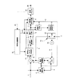
本実施の形態1では、映像の各フレーム画像をマクロブロックの単位に分割し、さらに、マクロブロック内を複数の形状のサブブロックに分割して個々に動き補償予測を可能とする動き補償予測手段を有する映像符号化・復号装置について説明する。本実施の形態1の映像符号化・復号装置の特徴は、動き補償予測の単位となる領域(ブロック)の形状やその大きさに応じて、従来例にて述べた仮想サンプルの精度を切り替えることと、それに伴い動きベクトルの符号化・復号方法も切り替えることの2点にある。本実施の形態1における映像符号化装置および復号装置の構成を図1および図2に示す。
【0013】
図1は、本実施の形態1における映像符号化装置の構成を示している。この映像符号化装置は、図3に示すように、減算器10、符号化モード判定部12、量子化部16、逆量子化部18、逆直交変換部19、切替器52、加算器53、フレームメモリ3、動き検出部2、動き補償部7、可変長符号化器6、送信バッファ24、符号化制御部22を有している。
【0014】
次に図3に示す映像符号化装置の動作を説明する。
▲1▼符号化装置の動作概要
図1の符号化装置において、入力映像信号1は、個々の映像フレームがマクロブロックに分割された単位で入力されるものとし、まず、動き検出部2において、フレームメモリ3に格納される参照画像4を用いてマクロブロック単位に動きベクトル5が検出される。動きベクトル5に基づいて動き補償部7において予測画像8が得られ、減算器10にて予測画像8と入力信号1との差分をとることによって予測残差信号9が得られる。
【0015】
符号化モード判定部12では、予測残差信号9を符号化する動き予測モード、フレーム内を符号化するイントラモードなど、マクロブロックの符号化方法を指定する複数のモードの中から、当該マクロブロックをもっとも効率よく符号化することができるモードを選択する。この符号化モード情報13は符号化対象情報として可変長符号化部6へ出力される。ここで、符号化モード判定部12にて符号化モード情報13として動き予測モードが選択される場合は、動きベクトル5が符号化対象情報として可変長符号化部6に受け渡される。
【0016】
また、符号化モード判定部12において選択された符号化対象信号は、直交変換部15、量子化部16を経て、直交変換係数データ17として可変長符号化部6へ受け渡される一方、その直交変換係数データ17は、逆量子化部18、逆直交変換部19を経たのち、切替器52へ出力される。
【0017】
切替器52では、符号化モード情報13に従って、その符号化モード情報13が動き予測モードを示している場合には、逆量子化および逆直交変換された直交変換係数データ17と、動き補償部7からの予測画像8と加算して局所復号画像21としてフレームメモリ3へ出力するか、あるいはその符号化モード情報13がイントラモードを示している場合には、逆量子化および逆直交変換された直交変換係数データ17をそのまま局所復号画像21として出力する。局所復号画像21は以降のフレームの動き予測に用いられるため、参照画像データとしてフレームメモリ3へ格納される。
【0018】
量子化部16では、符号化制御部22において決定される量子化ステップパラメータ23によって与えられる量子化精度で直交変換係数データの量子化を行う。この量子化ステップパラメータ23を調整することで出力の符号化レートと品質のバランスとをとる。一般には、可変長符号化の後、伝送直前の送信バッファ24に蓄積される符号化データの占有量を一定時間ごとに確認し、そのバッファ残量25に応じてパラメータ調整が行われる。具体的には、例えば、バッファ残量25が少ない場合は、レートを抑え気味にする一方、バッファ残量25に余裕がある場合は、レートを高めにして品質を向上させるようにする。なお、この、符号化制御部22において決定される量子化ステップパラメータ23は、可変長符号化部6へも出力される。
【0019】
可変長符号化部6では、動きベクトル5、量子化ステップパラメータ23、符号化モード情報13、直交変換係数データ17などの符号化対象データのエントロピー符号化を行い、送信バッファ24経由で、映像圧縮データ26として伝送する。
【0020】
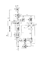
図2は、本実施の形態1における映像復号装置の構成を示している。この映像復号装置は、図2に示すように、可変長復号部27、逆量子化部18、逆直交変換部19、加算器55、切替器54、動き補償部7、フレームメモリ3を有している。
【0021】
▲2▼復号装置の動作概要
次に、図2に示す実施の形態1の映像復号装置の動作を説明する。
図2に示した復号装置では、映像圧縮データ26を受け取ると、可変長復号部27にて後述するエントロピー復号処理が行われて、動きベクトル5、符号化モード情報13、直交変換係数データ17、量子化ステップパラメータ23などが復元される。
【0022】
直交変換係数データ17、量子化ステップパラメータ23は、符号化側と同じ逆量子化部18と逆直交変換部19によって復号される。
【0023】
また、切替器54は、符号化モード情報13が動き予測モードを示している場合は、動き補償部7において復号された動きベクトル5と符号化モード情報13とに基づいて予測画像8を復元し出力する一方、イントラモードを示している場合は、0を出力する。
【0024】
そして、切替器54からの出力は、加算器55にて逆直交変換部19の出力である復号信号と加算されることによって復号画像21が得られる。復号画像21は以降のフレームの予測画像生成に用いられるため、フレームメモリ3に格納される。
【0025】
▲3▼動き補償予測の詳細動作
次に、符号化装置の動き検出部2、動き補償部7、フレームメモリ3を用いて行われる動き補償予測処理について、また、復号装置の動き補償部7、フレームメモリ3を用いて行われる動き補償処理について、それぞれ説明する。
【0026】
▲3▼−1 符号化装置における動き補償予測処理手順
図3に、符号化装置における動き補償予測処理のフローチャートを示す。以下、ステップごとに説明する。
【0027】
▲3▼−1−1 仮想サンプル精度の決定 ( ステップ S1)
図4に、本実施の形態1における動きベクトルの検出単位領域の構成を示す。同図において、16×16 MCとはマクロブロックそのものを動きベクトル検出単位とする。16×8 MCは縦方向に2分割した領域を、8×16 MCは横方向に2分割した領域をそれぞれ動きベクトル検出単位とする。8×8 MCはマクロブロックを4つの領域に均等分割し、それぞれを動きベクトル検出単位とする。さらに、本実施の形態1の場合、8×8 MCでは、個々の分割領域に対して、さらに縦2分割(8×4 MC)、横2分割(4×8 MC)、4分割(4×4 MC)の領域分割を可能とし、それぞれを動きベクトル検出単位とすることができるようにする。
【0028】
これは、一般に、細かい分割ではマクロブロック内部に複雑な動きが存在する場合に予測効率をあげることができる一方、多くの動きベクトル情報を伝送する必要がある。このようにマクロブロック内部で動きベクトル検出単位領域の形状を様々に適応化できるように構成すれば、局所的に最適な分割形状と動きベクトルの選択・検出を行いながら符号化を実行することができるからである。
【0029】
さて、個々の領域の動きベクトルの検出においては、従来例に示したとおり、仮想サンプルを用いた動き補償予測を用いる。ただし、従来の標準映像符号化方式などと異なり、本実施の形態1では、例えば、図4に示すように、個々の動きベクトル検出単位の領域の形状や大きさ等に関連付けて局所的に仮想サンプルの精度および動きベクトルの予測符号化方法を決定する。
【0030】
そして、本実施の形態1の符号化装置では、動き補償予測の単位である動きベクトル検出単位の領域の形状や大きさ等を示す形状情報を、符号化モード情報13の中の動き予測モードの一部として可変長符号化部6にて符号化し、復号装置に伝送する。
【0031】
したがって、本実施の形態1の復号装置では、符号化モード情報13だけによって、動き予測モードかイントラ符号化モードかであるかの符号化モード以外に、その符号化モード情報13の中の動き予測モードの一部として含まれる形状情報により、動き補償予測の単位である動きベクトル検出単位領域の形状や大きさ、およびその形状や大きさから一義的に決まる仮想サンプルの精度および動きベクトルの予測符号化方法を判定することができるので、仮想サンプル精度および動きベクトルの予測符号化方法の切り替えのための付加情報を一切必要としない。
【0032】
本実施の形態1では、その決定ルールとして、8×8 MCより小さい例えば8×4や、4×8、4×4サイズ等の動きベクトル検出単位領域では半画素精度の仮想サンプルを用いることとし、それ以上のサイズの動きベクトル検出単位領域では1/4画素精度の仮想サンプルを用いる。
【0033】
このルールを適用する理由として、動きベクトル検出単位領域の形状の選ばれ方が挙げられる。つまり、一般に、動きが均一でかつ動き速度の遅い領域では画面の空間解像度が保持され、テクスチャに対する視認度が向上する。こういった領域では大きな動きベクトル検出領域によりできるだけ動きベクトルを均一にし、動き領域の細分化に伴う領域間不連続を回避して信号の再現性を高めるとともに、仮想サンプルの精度を向上して予測効率を上げることが望ましい。逆に、動きが複雑であったり、動きの速度が視覚的に認知しにくい領域では画面の詳細なテクスチャが保存されず、視覚的には空間解像度が低く感じられる。こういった領域では、ある程度信号の再現性を犠牲にしても動きベクトルの本数を多くして予測効率を向上させることが望ましい。ただし、信号の空間解像度が低くなること、動きベクトルの情報量が多くなることから、仮想サンプルの精度は低く設定しても全体的な符号化効率の観点からは問題ないと考えられる。
【0034】
このような仮想サンプル精度の局所的設定を可能とすることにより、図5に示すように、8×4, 4×8, 4×4 MCの各モードについて、仮想サンプル生成に必要なメモリバンド幅を削減することができ、装置の簡略化にも効果的である。同図では、中段のモード状態に対して、上段はこれらのすべてのモードに対して1/4画素精度の仮想サンプルを用いることを想定した場合を示しており、かつ仮想サンプル生成のためにKタップのフィルタを用いる場合、すなわち、動きベクトル検出単位領域の端点からそれぞれK画素(K≧2)分の整数画素データをメモリから読み出す必要があることを示している。従来例では、K画素分の半分は折り返しで作成する例を示したが、ここでは折り返しを行わず、連続するK画素すべてを使用することで自然なフィルタリングを行うことを想定している。
【0035】
それに対し、本実施の形態1のように、これらの8×4, 4×8, 4×4 MCの各モードでは、半画素精度の仮想サンプルのみを使用することをあらかじめ決定しておくことにより、仮想サンプル生成のためにメモリから読み出す必要があるデータは、例えば従来例の半画素精度サンプル生成手順に従えば動きベクトル検出単位領域の周辺1画素分だけでよい。小さいサイズの動きベクトル検出単位領域では、個々の検出単位領域が空間的に不連続であるため、このことが極めて大きな意味をもつ。
▲3▼−1−2 予測誤差量の算出 ( ステップ S2 、 S3)
ステップS1で決定された仮想サンプル生成ルールに従い、それぞれのモードで個々の動きベクトル検出単位領域ごとに、各動きベクトル候補に対して予測画像を生成し、予測対象の動きベクトル検出単位領域との差分をとることにより予測誤差量を算出する。ここで、仮想サンプルについては、従来例の図17に示したような半画素精度サンプルの生成、図18に示したような1/4画素精度サンプルの生成を行うものとする。ただし、本実施の形態1の場合、図18の端点での画素値折り返し使用は行わないこととし、フィルタタップ数は一般性を持たせるため、以降Kタップとする。したがって、半画素精度の仮想サンプルを用いる8×8 MCより小さい例えば8×4や、4×8、4×4MC以下のモードの場合は、仮想サンプル生成に用いる画素データは、図5の下段に示すように、各8×4, 4×8, 4×4動きベクトル検出単位領域の周辺1画素分だけメモリから読み出すことになる(ステップS2)。
【0036】
予測誤差量の算出は(ステップS3)、ブロックマッチング法に基づき、各画素単位の誤差量を加算することで算出するのが一般的であり、誤差量としては主に二乗誤差 (p p')2もしくは差分絶対値 | p p' |が用いられる。ただし、pは予測対象の画素値、p'は予測画像内の対応する位置の画素値である。以下では、誤差量は、後者の差分絶対値を想定し、動きベクトル検出単位領域ごとあるいはマクロブロック内の総和としてSAD(Sum of Absolute Difference)というタームを用いることとする。
【0037】
▲3▼−1−3 動きベクトル符号量の算出 ( ステップ S4)
次いで、動きベクトルの符号量を算出する(ステップS4)。動きベクトルは、通常、周辺領域との相関が高いため、周辺領域の動きベクトルを予測値として、周辺領域の動きベクトルの予測値と、求めた動きベクトルとの間の予測差分値(MVD)を可変長符号化する。予測値の設定の方法には様々な手法が存在するが、ここでは予測値は所定のルールで定められたものとして動きベクトルの予測差分値(MVD)が得られるものとし、その詳細は割愛する。
【0038】
そして、本実施の形態1では、予測差分値(MVD)の符号量を求めるにあたり、▲3▼−1−1で定めた仮想サンプル精度を考慮する。
【0039】
図6を用いてステップS4における予測差分値(MVD)の求め方を説明する。なお、この動作は動き検出部2において実行されるが、最終的にステップS9で定まる動きベクトルを可変長符号化部6で符号化する場合にも同じルールが適用される。
【0040】
図6において、符号化対象となる動きベクトルをMV1〜MV5とし、所定の予測値設定ルールにしたがってMV1およびMV3に対して定められた予測ベクトルをPMV1、MV5に対して求められた予測ベクトルをPMV2とする。MV2はMV1を、MV4はMV3をそれぞれ予測値とするものとする。PMV1、PMV2はすでに符号化済みの値であるため適宜キャッシュしておけばよい。
【0041】
PMV1は、16×8 MCによる動きベクトル、MV5は8×8 MCによる動きベクトルであるため、▲3▼−1−1で定めたルールに従えば1/4画素精度の仮想サンプルを用いて決定された動きベクトルである。一方、MV1〜MV4およびPMV2は4×4 MCによる動きベクトルであるため、▲3▼−1−1で定めたルールに従えば半画素精度の仮想サンプルを用いて決定された動きベクトルである。つまり、PMV1,MV5と、MV1〜MV4と、PMV2との間には仮想サンプルの精度の違いが存在する。一方、動きベクトル符号化時にはあらかじめ予測ベクトルの値およびその仮想サンプル精度は既知である。このことを利用して、本実施の形態1では、予測差分値(MVD)を得るために適応的に動きベクトルの精度のあわせこみを行う。すなわち、以下の条件により、予測差分値(MVD)を求める。
【0042】
(1)条件1:自身(MV)が1/2画素精度の仮想サンプルを用いた予測により得られた動きベクトルである場合は、PMVの精度により、以下のように2つに分かれる。
条件1−1:PMVが同じ精度の仮想サンプルを用いた動きベクトルである場合
MVD = MV − PMV
【0043】
条件1−2:PMVが1/4画素精度の仮想サンプルを用いた動きベクトルである場合
MVD = MV − (PMV >> 1)
【0044】
(2)条件2:自身(MV)が1/4画素精度の仮想サンプルを用いた予測により得られた動きベクトルである場合は、PMVの精度により、以下のように2つに分かれる。
条件2−1:PMVが同じ精度の仮想サンプルを用いた動きベクトルである場合
MVD = MV − PMV
【0045】
条件2−2:PMVが1/2画素精度の仮想サンプルを用いた動きベクトルである場合
MVD = MV − (PMV << 1)
【0046】
ただし、x << yは、xに対する左方向へのyビットシフト演算、x >> yはxに対する右方向へのyビットシフト演算を示している。
【0047】
PMV1とMV1、MV3との間のルールとしては、上記条件1−2が適用され、MV1,MV3とMV2,MV4との間のルールとしては、上記条件1−1が適用され、PMV2とMV5との間のルールとしては条件2−2が適用される。
【0048】
この手順により、半画素精度の動きベクトルに対しては半画素精度でMVDを算出することが可能であり、常時1/4画素精度のMVDを用いるのに比べ符号量を削減することが可能である。
【0049】
▲3▼−1−4 コストの算出・最小コストの更新 ( ステップ S5 、 S6 、 S7)
上記の結果得られる予測差分値(MVD)を符号化することにより、符号量RMVDが得られる。これとステップS2におけるSADとを用いて、各動きベクトル候補について下記の式により、コストCを求める(ステップS5)。
【0050】
C = SADMV + λRMVD
(λは正の定数)
【0051】
動き補償部7は、上記のようにしてコストを算出するごとに、算出したコストが最小であるか否かを判断し(ステップS6)、それ以前に算出されたモードのコストよりも小さい値が現れれば(ステップS6"Y")、最小コストの更新を行うとともに、該当する予測モード、動きベクトルデータを保持しておく(ステップS7)。
【0052】
なお、ステップS1〜S7は、16×16 MC〜8×8 MCおよびそれ以下の分割モードすべてについて実行され、ステップS2〜S5は、各動きベクトル検出単位領域に対し、あらかじめ符号化装置において設定された所定の動きベクトル探索範囲内、すなわち水平・垂直方向の平行移動量の上限を規定する窓内のすべての動きベクトル候補に対して実行する。
【0053】
▲3▼−1−5 最終モード・動きベクトルの決定 ( ステップ S8 、 S9)
以上説明した▲3▼−1−4のコストの算出・最小コストの更新処理(ステップS5、S6、S7)が終了したら、続いて全予測モードでコストを算出したか否かを判断し(ステップS8)、全予測モードでコスト算出をしていなければ(ステップS8"N")、以上説明した▲3▼−1−4までに示す処理(ステップS1〜S7)を行う一方、全予測モードでコスト算出をした場合には(ステップS8"Y")、▲3▼−1−4で得られるマクロブロックの単位のコストのうち、最もコストの小さい予測モードを、実際に符号化する予測モードとして決定する(ステップS9)。また、予測モードの決定と同時に、当該予測モードに対応した動きベクトルが決定されることになる(ステップS9)。
【0054】
以上説明した動き補償予測処理により決定された予測モードは、最終的にはイントラモードとの比較で最適なモードが決定され、符号化モード情報13として可変長符号化部6を通じてマクロブロック単位に映像圧縮データ26に多重される。また、決定された動きベクトルデータ5は、▲3▼−1−3の手順でMVDデータ化され、可変長符号化部6を通じてマクロブロック単位に映像圧縮データ26に多重される。
▲3▼−2 復号装置における動き補償処理
図7に、復号装置側における動き補償処理のフローチャートを示す。以下、フローチャートを参照して復号装置側における動き補償処理を詳細に説明する。
【0055】
▲3▼−2−1 予測モード、動きベクトルデータの復号 ( ステップ S10)
図2に示すように復号装置側では、可変長復号部27が、例えば図1に示す符号化装置から出力された映像圧縮データ26からマクロブロック単位に符号化モード情報13を復号する。これがインター(フレーム間予測)モードを示す場合、可変長復号部27は、続いて予測差分値(MVD)の形式で符号化されている動きベクトルデータ5を復号する(ステップS10)。
【0056】
▲3▼−2−2 仮想サンプル精度の決定 ( ステップ S11)
符号化モード情報13がインター(フレーム間予測)モード、すなわち、本実施の形態1の場合例えば図4に示すいずれかの動き補償予測モードを表す場合は、符号化装置における動き補償予測処理手順として説明した▲3▼−1−1の手順(ステップS1)の場合と同様に、仮想サンプル精度の決定を行う。つまり、符号化装置側の動作で説明したように、動き補償予測の単位、すなわち動きベクトル検出単位の領域の形状や大きさ等を示す形状情報は、符号化モード情報13の中の動き予測モードの一部として可変長符号化部6で符号化されているので、復号装置側では、復号した符号化モード情報13の中に動き予測モードの一部として含まれる形状情報により、動き補償予測の単位である動きベクトル検出単位領域の形状や大きさ、およびその形状や大きさから一義的に決まる仮想サンプルの精度を判定することができる
【0057】
▲3▼−2−3 動きベクトルの復号 ( ステップ S12)
次いで、予測差分値(MVD)の形式で復号された動きベクトルを、実際に各動きベクトル適用単位領域、すなわち符号化装置の説明における各動きベクトル検出単位領域に対して使用された動きベクトルデータ(MV)へ復号する(ステップS12)。この手順は、本実施の形態1では、可変長復号部27等において行われ、符号化装置における動き補償予測処理手順として説明した▲3▼−1−3の逆の手順をとればよい。つまり、本実施の形態1の場合、仮想サンプルの精度の判定の場合と同様に、符号化モード情報13の中に動き予測モードの一部として含まれる形状情報から動きベクトルの予測復元方法が一義的に決まるので、その形状情報に基づいて動きベクトルの予測復元方法を切り換えて動きベクトルを復号する。図6を用いて▲3▼−1−3の手順と対比させて説明する。
【0058】
▲3▼−1−3と同様、ここでは符号化装置・復号装置の間であらかじめ取り決められた共通の予測値設定方法を用いる。まず、MV1、MV3に対しては、PMV1を用いて、
【0059】
MV1 = MVD1 + (PMV1 >> 1)
MV3 = MVD3 + (PMV1 >> 1)
【0060】
として復号される。ここで、MVD1はMV1に対応する予測差分値(MVD)、MVD3はMV3に対応する予測差分値(MVD)である。
【0061】
また、MV2,MV4に対しては、
MV2 = MVD2 + MV1
MV4 = MVD4 + MV3
【0062】
MV5に対しては、
MV5 = MVD5 + (PMV2 << 1)
として復号を行う。
【0063】
すなわち、以下の条件式に従う。
(1)条件1:自身(MV)が1/2画素精度の仮想サンプルを用いた予測により得られた動きベクトルである場合は、PMVの精度により、以下のように2つに分かれる。
条件1−1:PMVが同じ精度の仮想サンプルを用いた動きベクトルである場合
MV = MVD + PMV
【0064】
条件1−2:PMVが1/4画素精度の仮想サンプルを用いた動きベクトルである場合
MV = MVD + (PMV >> 1)
【0065】
(2)条件2:自身(MV)が1/4画素精度の仮想サンプルを用いた予測により得られた動きベクトルである場合は、PMVの精度により、以下のように2つに分かれる。
条件2−1:PMVが同じ精度の仮想サンプルを用いた動きベクトルである場合
MV = MVD + PMV
【0066】
条件2−2:PMVが1/2画素精度の仮想サンプルを用いた動きベクトルである場合
MV = MVD + (PMV << 1)
なるルールを用いることで動きベクトルの復号を行う。
【0067】
▲3▼−2−4 予測画像生成 ( ステップ S13 、 S14)
▲3▼−2−2で決定された仮想サンプル生成ルールに従い、▲3▼−2−3で復号された動きベクトルデータを用いて、個々の動きベクトル適用単位領域ごとに予測画像を生成する。仮想サンプルについては、従来例の図17に示したような半画素精度サンプルの生成、図18に示したような1/4画素精度サンプルの生成を行うものとする。ただし、図18の端点での画素値折り返し使用は行わないこととし、フィルタタップ数は一般性を持たせるため、以降Kタップとする。したがって、半画素精度の仮想サンプルを用いる8×8 MCより小さい例えば8×4や、4×8、4×4 MC以下のモードの場合は、符号化装置における動き補償予測処理のステップS2の場合と同様に、仮想サンプル生成に用いる画素データは図5の下段に示すようにメモリから読み出して、予測画像を生成することになる。
【0068】
従って、以上の構成をもつ本実施の形態1の映像符号化装置または復号装置を用いることにより、動きの局所的な状況に適応して、動き補償予測単位となるブロックの大きさに応じて動き補償予測を行う際の仮想サンプルの精度を切り替えると共に、動きベクトルの算出方法も切り替えるようにしたので、メモリバンド幅を抑えながら画質を保った圧縮符号化を行うことが可能となる。特に、メモリバンド幅削減は、特に映像再生を主とするプレーヤを、携帯電話、携帯情報端末などにハードウエア実装する際に、映像復号処理実装の簡略化、消費電力化に著しい効果を発揮する。
【0069】
なお、上記実施の形態1の説明では、動き補償予測単位となるブロックの大きさに応じて動き補償予測を行う際の仮想サンプルの精度を切り替えると共に、動きベクトルの算出方法も切り替えるようにしたが、本発明では、これに限らず、動き補償予測単位となるブロックの大きさに応じて動き補償予測を行う際の仮想サンプルの精度を切り替えるのみで、動きベクトルの算出方法は切り替えないようにしても勿論よい。ただし、この場合には、、メモリバンド幅を抑えながら符号化効率を向上させることができるが、動き補償予測の精度を低くした分だけ画質が落ちることになる。このことは、以下のすべての実施の形態においても適用される。
【0070】
また、本実施の形態1では、符号化装置における▲3▼−1−1、復号装置における▲3▼−2−2において仮想サンプル精度を決定した後、使用する仮想サンプル精度に合わせて仮想サンプル生成のためのフィルタ処理を変更するように構成した。1/4画素精度の場合はまず半画素精度仮想サンプルを、図18のように整数画素データを用いてK(=8)タップフィルタによって生成し、それによって生成された半画素精度仮想サンプルをさらに線形補間することによって1/4画素精度サンプルを生成した。半画素精度の場合は、整数画素データの線形補間によって半画素精度サンプルを生成する。この場合は動き補償予測対象ブロックサイズ+周辺1画素分だけメモリから読み出せば済む。このフィルタ処理の違いにより、小さいブロックサイズでの動き補償予測ではメモリから読み出すデータ量を低減することをポイントとしたが、このフィルタ処理そのものは仮想サンプル精度に依存せずに一意に定めるように構成してもよい。つまり、半画素精度サンプルのみを使用する小さいブロックサイズの場合であっても、Kタップフィルタで半画素精度サンプルを構成するようにしても良い。このフィルタ処理の固定化により、メモリから読み出すデータ量に関してはメモリバンド幅削減にはならないが、一方で、Kタップフィルタで生成された半画素サンプルから1/4画素精度のサンプルを作り出す処理は必要なく、かつ▲3▼−1−3、▲3▼−2−3のように動きベクトルの表現精度は依然として制限することができ、動きベクトルの符号化を効率化することが可能となる。
【0071】
さらに、本実施の形態1では、常に映像入力の単位をフレームとして記述したが、奇数フィールドと偶数フィールド等のインタレース映像入力を想定する場合には、厳密にはフレームは2枚のフィールド画像データの組合わせで定義される。この場合、本実施の形態1の映像符号化装置および映像復号装置は、各フィールドごとにマクロブロックを構成して符号化・復号する場合にも適用可能であることは明らかである。このことは、以下のすべての実施の形態においても適用される。
【0072】
また、本実施の形態1では、8×8より小さいサイズとして8×4や、4×8、4×4サイズの動きベクトル検出単位領域では半画素精度の仮想サンプルを用いることとし説明したが、本発明ではこれに限らず、8×8より小さいサイズとして4×2や、2×4等の8×4や4×8、4×4サイズ以外であっても良いし、8×8を基準としてではなく、8×16や16×8等他のサイズを基準にして大小により仮想サンプルの精度を変えても良い。またさらに、8×8等の所定サイズより小さいサイズの動きベクトル検出単位領域において半画素精度の仮想サンプルを用いるのでなく、所定サイズより小さいサイズの動きベクトル検出単位領域においては整数画素精度として動き補償予測を行うようにしても勿論よい。このようにすれば、画質は多少落ちるものの、メモリバンド幅は大幅に削減することが可能となる。要は、符号化単位であるマクロブロックをさらに分割して動き補償予測を行う動きベクトル検出単位領域において、メモリバンド幅が問題となる所定のブロックサイズを基準に動きベクトルの探索精度を下げて、メモリバンド幅を削減すれば良いのである。このことは、以下のすべての実施の形態においても適用される。
【0073】
実施の形態2. ( Bフレームおよび複数参照フレーム予測の例 )
本実施の形態2では、実施の形態1に述べた映像符号化装置および映像復号装置に加えて、複数のフレームメモリからなるフレームメモリ群を用意して、マクロブロックまたはマクロブロックを分割した動き補償予測ブロックの単位で、複数のフレームメモリを使用して動き補償予測を行うことを可能とする装置について説明する。
【0074】
図8に、本実施の形態2における映像符号化装置の構成を示す。同図において、図1に示す実施の形態1の符号化装置との違いは、フレームメモリ3がフレームメモリ群28に置き換わっており、動き検出部2、動き補償部7がフレームメモリ群28を利用して複数のフレームメモリから最適な予測画像と動きベクトルを得るように構成されている点である。動き検出部2、動き補償部7は、図1の符号化装置と比べて動作の詳細が異なるが、以下ではその前提で同一図番にて説明を行うものとする。
【0075】
▲1▼符号化装置の動作概要
入力映像信号1は、個々の映像フレームがマクロブロックに分割された単位で入力されるものとし、まず、動き検出部2において、フレームメモリ群28に格納される複数の参照画像4を用いてマクロブロック単位に動きベクトル5が検出される。
【0076】
複数の参照画像を用いた動きベクトル検出の方法としては、例えばISO/IEC13818-2(MPEG-2ビデオ規格)で開示される両方向予測がある。
【0077】
図9に、ISO/IEC13818-2(MPEG-2ビデオ規格)で開示される両方向予測の実行の方法を示す。。同図において、F(t)が現在符号化対象の入力映像フレームであり、フレームメモリ中に格納される参照画像にはF'()として区別をした。B(x,y,t)がF(t)内のある動き補償予測単位のブロックであるとする。両方向予測では、B(x,y,t)の位置から動きベクトルMVf(B(x,y,t))だけ移動させた過去の参照画像F'(t-1)中のブロック画像を前方向予測画像Pf(B(x,y,t))とし、B(x,y,t)の位置から動きベクトルMVb(B(x,y,t))だけ移動させた未来の参照画像F'(t+1)中のブロック画像を後方向予測画像Pb(B(x,y,t))とし、Pf(B(x,y,t))とPb(B(x,y,t))との加算平均でB(x,y,t)の予測画像Pi(B(x,y,t))を生成する。MVf(B(x,y,t))やMVb(B(x,y,t))は、動き検出部2において、それぞれ対応する参照画像上の与えられた探索範囲内でB(x,y,t)との絵柄の類似度が高い、もしくは画素差分が最も小さくなるブロック画像を探し出し、その偏移分を検出した値に該当する。
【0078】
図10に、複数の参照画像を用いて動きベクトルを検出する片方向予測の一例を示す。図10に示す別の例は、例えば、特開平4-127689号公報に開示された過去の複数の参照画像をフレームメモリ群28に格納できるように構成された符号化装置であって、動き補償予測単位のブロックB(x,y,t)に類似するブロック画像が直前の参照画像F(t-1)にはなく、さらにその前の参照画像F(t-2)に見つかるような場合でも、動きベクトルMVt-2(B(x,y,t))を用いて動き補償予測が行えるため、映像の局所的な性質に適応した動き補償予測が行えるようにしたものである。
【0079】
本実施の形態2では、複数のフレームメモリからなるフレームメモリ群28を有しているので、その複数のフレームメモリそれぞれに格納された複数の参照画像を用いて動きベクトルを検出する図9または図10のいずれの構成の符号化装置にも適用可能である。
【0080】
さて、本実施の形態2では、上記の図9または図10の事例のように検出された動きベクトル5には、その動きベクトル5がフレームメモリ群28のうちでどのフレームメモリを参照したかを指示する情報が組になって明示されている。
【0081】
このため、本実施の形態2の動き補償部7では、それらの情報に従ってフレームメモリ群28の中の適切なフレームメモリを参照することで予測画像8が得られる。さらに入力信号1との差分をとることによって予測残差信号9が得られる。なお、動きベクトル5がフレームメモリ群28の中のどのフレームメモリを参照したかを指示する情報は、動きベクトル5そのものでなく、別情報としてデコーダに通知するための符号化データの形で表現されてもよい。
【0082】
また、本実施の形態2の符号化モード判定部12では、予測残差信号9を符号化する動き予測モード、フレーム内符号化を行うイントラモードなど、マクロブロックの符号化方法を指定する複数のモードの中から、当該マクロブロックをもっとも効率よく符号化することができるモードを選択して符号化モード情報13として出力する。動き予測モードとは、実施の形態1に説明した図4に示すようなマクロブロック内分割の形状や、図9においてPf(B(x,y,t))だけを用いて予測を行うか、Pb(B(x,y,t))だけを用いて予測を行うか、それらの加算平均をとるかなどを識別する情報などに該当する。この符号化モード情報13は、符号化対象情報として可変長符号化部6に受け渡される。符号化モード情報13として動き予測モードが選択される場合は、動きベクトル5が符号化対象情報として可変長符号化部6に受け渡され、可変長符号化される。
【0083】
なお、符号化モード判定部12において選択された符号化対象信号11の符号化である直交変換部以降の処理は、実施の形態1に同じであるため、説明を省略する。
【0084】
次に、本実施の形態2における映像復号装置について説明する。
図11に、本実施の形態2における映像復号装置の構成を示す。同図において、図2に示す実施の形態1の復号装置との違いは、フレームメモリ3がフレームメモリ群28に置き換わっており、動き補償部7が可変長復号部27で復号される動きベクトル5と符号化モード情報13とにしたがって、フレームメモリ群28のうち指定されたフレームメモリから予測画像を得るように構成される。動き補償部7は図2の復号装置と比べて動作の詳細が異なるが、以下ではその前提で同一図番にて説明を行う。
【0085】
▲2▼復号装置の動作概要
復号装置では映像圧縮データ26を受け取ると、まず可変長復号部27にて後述するエントロピー復号処理が行われて、動きベクトル5、符号化モード情報13、直交変換係数データ17、量子化ステップパラメータ23などが復元される。なお、直交変換係数データ17、量子化ステップパラメータ23による予測残差信号の復元処理は、実施の形態1の復号装置と同一であるため、説明を省略する。
【0086】
そして、実施の形態1の復号装置の場合と同様に、動き補償部7は、可変長復号部27にて復号された動きベクトル5と符号化モード情報13とに基づき、フレームメモリ群28の中の所定のフレームメモリに格納される参照画像を用いて予測画像8を復元する。
【0087】
切替器54は、符号化モード情報13に基づいて、動き予測モードであれば動き補償部7からの予測画像8を加算器55へ出力する一方、イントラモードであれば0を加算器55へ出力する。加算器55では、これら切替器54からの出力を、逆直交変換部19の出力である復号信号と加算することによって復号画像21を得る。復号画像21は以降のフレームの予測画像生成に用いられるため、フレームメモリ群28に格納される。
【0088】
▲3▼動き補償予測の動作
符号化装置における動き検出部2、動き補償部7およびフレームメモリ群28を用いて行われる動き補償予測処理や、復号装置における動き補償部7およびフレームメモリ群28を用いて行われる動き補償処理については、図9や図10から明らかなように、フレームメモリごとの処理単位に分離して考えることができる。符号化装置側にて個々の参照画像(F'(t-1)など)が格納されるフレームメモリを用いて動きベクトル5と予測画像8を得る処理を実施の形態1にて説明した▲3▼−1−1〜▲3▼−1−5からなる▲3▼−1の符号化装置における動き補償予測処理処理、また復号装置側にて個々の参照画像(F'(t-1)など)が格納されるフレームメモリを用いて予測画像8を得る処理を実施の形態1の▲3▼−2−1〜▲3▼−2−4からなる▲3▼−2の復号装置における動き補償処理とみなすことができ、実施の形態1に記載した手順をそのまま適用可能である。
【0089】
従って、以上の構成をもつ本実施の形態2の映像符号化装置または復号装置によれば、上記実施の形態1の映像符号化装置または復号装置の場合と同様に、動きの局所的な状況に適応して動き補償予測単位となるブロックの大きさに応じて、従来例にて述べた仮想サンプルの精度を切り替えると共に、動きベクトルの符号化・復号方法も切り替えているので、メモリバンド幅を抑えながら画質を保った圧縮符号化を行うことが可能となる。
【0090】
特に、図9に示すように前方向も後方向も含めた両方向の複数のフレームメモリから予測画像を生成する必要がある場合や、図10に示す片方向でも複数のフレームメモリから予測画像を生成する必要がある場合には、それだけフレームメモリからの読み出し画素数が増大することは明らかであるが、本実施の形態2によれば、動きが複雑等で精緻な動き補償予測の効果が薄れる場合には、仮想サンプル精度を半画素、あるいは整数画素までに限定して動きベクトルの表現精度も低くすることで、符号化効率を保ちながらフレームメモリアクセス時のメモリバンド幅を低減することができる。その結果、本実施の形態2によれば、特に複数のフレームメモリに格納された複数の参照画像を参照して動き補償予測を行う両方向予測等の場合には、符号化装置における動きベクトル検出処理ならびに復号装置の予測画像生成処理に関して著しい演算量削減効果が期待される。
【0091】
また、本実施の形態2では、複数のフレームメモリを有しているので、図9に示す通常の両方向予測や、図10に示す過去の複数の参照画像からの片方向予測だけでなく、例えば、通常はその複数のフレームメモリの内容を復号画像をもって逐次更新を行う一方、複数のフレームメモリのうち一のフレームメモリの内容のみ更新しないことが指示等された場合には、その複数のフレームメモリのうち一のフレームメモリの内容のみ更新しないようにして、複数のフレームメモリを逐次更新を行うショートタームフレームメモリと、次のイベントが発生するまで参照画像が更新されないロングタームフレームメモリとして使用して、ショートタームフレームメモリとロングタームフレームメモリの参照画像を用いて動き補償予測を行うようにしても勿論かまわない。このようにすれば、動画像信号の時間的な局所的特性に応じて複数のフレームメモリを弾力的に使用することが可能となり、フレームメモリを効率的に使用しつつも、符号化シーケンスに影響されずに高い予測効率を維持しながら符号化を行うことができることになる。
特に、動きの局所的な状況に適応して、動き補償予測単位となるブロックの大きさに応じて動き補償予測を行う際の仮想サンプルの精度を切り替えたり、動きベクトルの算出方法も切り替えるだけでなく、その動き補償予測を行う領域単位で適応的に図9に示す両方向予測や図10に示す片方向予測等を切り替えたり、あるいはその領域単位で通常はその複数のフレームメモリの内容を復号画像をもって逐次更新を行うのと、複数のフレームメモリのうち一のフレームメモリの内容のみ更新しないことが指示等された場合におけるその複数のフレームメモリのうち一のフレームメモリの内容のみ更新しないようにすることを適応的に切り替えるようにすれば、空間的だけでなく時間的な局所的な動きなどの各種の特徴が現れる場合でも、メモリバンド幅を増大させることなく、符号化効率を向上させると共に、画質も向上させることが可能となる。
【0092】
実施の形態3. ( 仮想画素算出手段の切り換えフラグ )
本実施の形態3では、実施の形態1や実施の形態2に述べた映像符号化装置および映像復号装置に対し、さらに、仮想サンプル算出方法の適応切り換えの自由度を向上させる仮想サンプル算出方法切り換えフラグを導入した映像符号化装置および映像復号装置について説明する。
【0093】
実施の形態1および2に示した映像符号化装置および映像復号装置では、図4の、8×8 MCより小さい例えば8×4や、4×8、4×4サイズでの動き補償予測を半画素精度の仮想サンプルに限定して予測を行うように構成したが、映像によっては、8×8 MCより小さいよりも小さい単位での動き補償予測であっても予測効率向上のために1/4画素精度の動き補償予測を必要とする場合がありうる。例えば、動き補償予測対象の画像が十分にテクスチャを保存していながら、入力信号に載った微妙な雑音成分が動きベクトルのばらつきを生じさせてしまうような場合がありうる。このような場合では、単純に動きの複雑さのみを仮定して仮想サンプル精度を固定化させてしまうのでなく、映像の局所的な信号状況に適応化させて、最適な仮想サンプル精度を選択させることで、真に微細な仮想サンプル精度を必要とする場合にのみ必要最小限の演算量を追加させるように装置構成を行うことができ、さらなる映像符号化品質の向上を図ることが可能である。
【0094】
図12に、本実施の形態3における映像符号化装置の構成を示す。
図13に、本実施の形態3における映像復号装置の構成を示す。図12および13において、上記に述べた動き補償予測精度の適応化のための役割を果たすのが、動き補償予測の精度切り替え信号である仮想サンプル精度切り換えフラグ29であり、それ以外の点は、図1または図2に示す実施の形態1の映像符号化装置または映像復号装置と同様である。
【0095】
次に動作を説明する。
図12に示す本実施の形態3の符号化装置側では、仮想サンプル精度切り換えフラグ29は、符号化装置内部における入力映像データの事前解析もしくは符号化装置を含むシステムにおける外的要因、例えば送信バッファ24のバッファ残量や符号化ビットレート等の送信環境などに基づいて、所定の映像データ単位でフラグの値の決定が行われ、動き検出部2および動き補償部7に入力される。動き検出部2および動き補償部7では、入力する仮想サンプル精度切り換えフラグ29に基づいて、以下に示すように、切り換え単位を適応的に変化させながら、動き補償予測の際の仮想サンプル精度や、動きベクトルの算出方法を変えて、動きベクトルおよび予測画像を生成する。
【0096】
仮想サンプル精度切り換えフラグ29の値については、例えば以下のような意味付けを考えることができる。具体的には、仮想サンプル精度切り換えフラグ29がONまたは1であるとは、切り換え単位となる映像データ単位内において、すべての8×8MC未満のブロックサイズでの動き補償予測を1/4画素精度の動き補償予測によって行う、ということを指示する。つまり、この場合は従来例の図18に示したような多タップフィルタを用いることを前提に多くの画素データをフレームメモリから読み出すことを許容しても予測効率を優先する。この際は、すべての動きベクトルが同一精度であるため、▲3▼−1−3に述べた動きベクトルの精度変換を伴う動きベクトル予測と符号量算出は実施しない。
【0097】
これに対し、仮想サンプル精度切り換えフラグ29がOFFまたは0であるとは、すべての8×8MC未満である図4の場合であれば8×4や、4×8、4×4サイズでのブロックサイズでの動き補償予測を半画素精度の動き補償予測を実施せよ、ということを指示する。この指定は、従来例の図17に示したような半画素精度の仮想サンプルでも必要十分な予測効率が得られるケースで用いられる。この際は、8×8MC未満のブロックサイズでは、動きベクトルの精度が異なるため、適宜、▲3▼−1−3に述べた動きベクトルの精度変換を伴う動きベクトル予測と符号量算出を実施することになる。なお、ON/OFFと、1/0の関係は、これに固定化されるものではなく、もちろん逆の関連付けを行ってもよい(ON=0、OFF=1)。
【0098】
仮想サンプル精度切り換えフラグ29の切り換え単位となる映像データ単位は、例えばマクロブロック、スライス(複数のマクロブロックから構成される映像フレームの単位領域)、フレームやフィールド(インタレース信号の場合)、シーケンス(複数の映像フレームから構成される時系列単位)などがありうる。
【0099】
このように符号化側で設定された仮想サンプル精度切り換えフラグ29は、所定の映像データ単位で可変長符号化部6においてビットストリームに多重化される。
【0100】
復号装置では、図13に示すように、可変長復号部27が仮想サンプル精度切り換えフラグ29の値を復号し、同フラグ29が付与された映像データ単位ごとに上記規範に基づいて、可変長復号部27は、必要に応じて▲3▼−2−3に述べた精度適応の動きベクトル5の復号処理を行い、動き補償部7は、仮想サンプル精度切り換えフラグ29が指定する精度の仮想サンプル生成処理と動きベクトル5に基づいて、予測画像8の生成を行うように構成する。
【0101】
従って、以上の構成を有する本実施の形態3の映像符号化装置および映像復号装置によれば、予測効率と演算負荷とのトレードオフを自在に制御することが可能となり、自由度の高い映像符号化を行うことができるようになる。
【0102】
なお、本実施の形態3は、実施の形態1の事例をもとに説明したが、仮想サンプル精度切り換えフラグ29が実施の形態2における映像符号化装置および映像復号装置にも適用可能であることはいうまでもない。
【0103】
実施の形態4. ( 空間予測部あり )
上記実施の形態1〜3の画像符号化装置および画像復号装置側では、イントラモードの場合、空間予測を行わない通常のフレーム内符号化により説明したが、この実施の形態4では、イントラモードとしてフレーム内で空間予測を用いて動画像信号と予測信号との差分信号を符号化するイントラ予測モードにより符号化を行う空間予測部10aを設けた例について説明する。
【0104】
図14に、図1に示す実施の形態1の符号化装置に対し空間予測部10aを追加した本実施の形態4の符号化装置の構成を示す。図14に示すように、本実施の形態4の符号化装置では、空間予測部10aを追加したので、空間予測部10aから可変長符号化部14へイントラ予測モード14を出力すると共に、切替器52には実施の形態1〜3の場合のイントラモードの0入力の代わりに空間予測部10aから空間予測画像20が出力されることになる。その他は、実施の形態1と同様である。
【0105】
図15に、図2に示す実施の形態1の復号装置から空間予測部10aを追加した本実施の形態4の復号装置の構成を示す。図15に示すように、本実施の形態4の復号装置では空間予測部10aを追加したので、すなわち図14に示すように符号化装置側にて空間予測部10aを追加したので、可変長復号部27から空間予測部10aへイントラ予測モード14が出力されると共に、切替器54には実施の形態1〜3の場合のイントラモードの0入力の代わりに空間予測部10aから空間予測画像20が出力されることになる。その他は、実施の形態1と同様である。
【0106】
簡単に動作を説明すると、図14に示す本実施の形態4の符号化装置では、空間予測部10aによるイントラ予測モード符号化が行われる場合には、空間予測部10aから可変長符号化部14へイントラ予測モード14が出力され、可変長符号化部6では、動きベクトル5、量子化ステップパラメータ23、符号化モード情報13、直交変換係数データ17と共にイントラ予測モード14もエントロピー符号化を行い、送信バッファ24経由で、映像圧縮データ26として伝送する。そして、本実施の形態4の切替器52では、符号化モード情報13に従って、その符号化モード情報13が時間方向の予測である動き予測モードを示している場合には、逆量子化および逆直交変換された直交変換係数データ17と、動き補償部7からの予測画像8と加算して局所復号画像21としてフレームメモリ3へ出力するか、あるいはその符号化モード情報13が空間方向の予測であるイントラ予測モードを示している場合には、逆量子化および逆直交変換された直交変換係数データ17と、空間予測画像20とが加算されて局所復号画像21として出力され、降のフレームの動き予測に用いられるため、参照画像データとしてフレームメモリ3へ格納される。
【0107】
その一方、図15に示す本実施の形態4の復号装置では、可変長復号部27がイントラ予測モード14を復号され、空間予測部10aへ出力され、空間予測画像20が復元される。そして、本実施の形態4の切替器54では、可変長復号部27からの符号化モード情報13に基づいて、時間方向の予測である動き予測モードであれば動き補償部7からの予測画像8を加算器55へ出力する一方、空間方向の予測であるイントラ予測モードを示している場合には空間予測画像20を加算器55へ出力する。加算器55では、これら切替器54からの出力を、逆直交変換部19の出力である復号信号と加算することによって復号画像21を得て、以降のフレームの予測画像生成に用いられるため、フレームメモリ3に格納される。
【0108】
従って、本実施の形態4の画像符号化装置および画像復号装置側によれば、上記実施の形態1の画像符号化装置および画像復号装置におけるイントラモードの代わりに、フレーム内で空間予測を用いて動画像信号と予測信号との差分信号を符号化するイントラ予測モードを採用するようにしたので、上記実施の形態1と同様の効果が得られると共に、上記実施の形態1にて行う通常のイントラモードよりも、圧縮効率を向上させることができる。
【0109】
なお、この実施の形態4では、図1に示す実施の形態1の符号化装置、および図2に示す実施の形態1の復号装置に対し空間予測部10aを追加したものを実施の形態として図示して説明したが、本発明では、これに限らず、図8および図11に示す実施の形態2の符号化装置および復号装置に対し空間予測部10aを追加することも、さらには図12および図13に示す実施の形態3の符号化装置および復号装置に対し空間予測部10aを追加することも可能であり、これらの場合も、上記と同様に説明することができる。
【0110】
実施の形態5. ( 応用製品 )
上記実施の形態1〜4では、画像符号化装置または画像復号装置等の要素製品として説明したが、この実施の形態5では、実施の形態1〜4の画像符号化装置または画像復号装置等の要素製品が実装される最終製品について簡単に説明する。
【0111】
図16は、実施の形態1〜4の画像符号化装置および画像復号装置等の要素製品が実装された実施の形態6の携帯電話の構成を示している。この携帯電話は、図16に示すように、送受信部71、ベースバンド゛処理部72、制御部73、音声コーデック74、ビデオコーデック75、インタフェース76、カメラ77、ディスプレイ78、マイク・スピーカ79、アンテナ80等を備えて構成されており、このビデオコーデック75が上記実施の形態1〜4のいずれかの画像符号化装置および画像復号装置が搭載されることになる。
【0112】
従って、本実施の形態6の携帯電話によれば、実施の形態1〜4の画像符号化装置および画像復号装置等の要素製品を実装することにより、動きの局所的な状況に適応して、メモリバンド幅を抑えながら画質を保った圧縮符号化を行うことが可能となり、メモリバンド幅削減により映像復号処理実装の簡略化、消費電力化に著しい効果を発揮する。
【0113】
なお、本実施の形態5では、実施の形態1〜4の画像符号化装置または画像復号装置等の要素製品が実装される最終製品として、画像符号化装置および画像復号装置の双方をビデオコーデック75に搭載した携帯端末を一例に説明したが、本発明では、これに限らずに、図示まではしないが、実施の形態1〜4の画像符号化装置のみを搭載した放送装置や、実施の形態1〜4の画像復号装置のみを搭載したDVDプレーヤ等にも適用できることは勿論である。これら映像再生を主とするプレーヤや、携帯電話、携帯情報端末などにハードウエア実装する際に、メモリバンド幅削減により映像復号処理実装の簡略化、消費電力化に著しい効果を発揮する。
【0114】
【発明の効果】
以上説明したように、本発明に係る画像符号化装置および方法によれば、動き補償予測の単位となる領域の形状に応じて、予測画像の構成要素となる仮想画素の精度を切り換えて予測画像の候補を生成し、該複数の予測画像候補のうち予測効率が大きい予測画像を与える動きベクトルを生成すると共に、生成した動きベクトルに基づき、動き補償予測の単位となる領域の形状に応じて予測画像の構成要素となる仮想画素の精度を切り換えて予測画像をするようにしたので、動き補償予測単位となる領域の形状に応じて動き補償予測の精度を切り換えることにより、メモリバンド幅を抑えながら符号化効率を向上させた圧縮符号化を行うことが可能となる。
【0115】
また、動き補償予測単位となる領域の形状に応じて動き補償予測の精度を切り換えると共に、動き補償予測の単位となる領域の形状に応じて動きベクトルの予測符号化方法も切り換えて適応的に切り変えて符号化を行うことにより、例えば、メモリバンド幅を抑えながら符号化効率を向上させた分だけ動きベクトルに多く符号量を割り当てることが可能となり、メモリバンド幅を抑えながら画質も保つこと等もできることになる。
【0116】
また、本発明に係る画像復号装置によれば、符号化ビットストリームを入力して上記差分信号と、動きベクトルと、上記動き補償予測の単位となる領域の形状を示す形状情報とを復号し、その動き補償予測の単位となる領域の形状を示す形状情報に基づいて予測画像の構成要素となる仮想画素の精度を切り換え、切り換えられた精度にしたがい上記復号された動きベクトルを用い上記参照画像を参照して予測画像を生成し、上記復号された上記差分信号と、上記動き補償によって生成された予測画像とを加算して動画像信号を復元するようにしたので、メモリバンド幅を抑えながら符号化効率を向上させて圧縮符号化が行われた符号化ビットストリームを復号することが可能となる。
【0117】
特に、メモリバンド幅削減は、特に映像再生を主とするプレーヤを、携帯電話、携帯情報端末などの映像符号化装置、映像復号装置のハードウエア実装する際に、映像復号処理実装の簡略化、消費電力化に著しい効果を発揮するので、これら符号化装置、復号装置の実装コストを抑えながら伝送・記録効率の高い映像符号化装置、映像復号装置を提供することが可能となる。
【図面の簡単な説明】
【図1】 実施の形態1における映像符号化装置の構成を示す図。
【図2】 実施の形態1における映像復号装置の構成を示す図。
【図3】 符号化装置における動き補償予測処理を示すフローチャート。
【図4】 実施の形態1における動きベクトルの検出単位領域の構成を示す。
【図5】 実施の形態1による仮想サンプル精度の局所的設定により、8×4, 4×8,4×4 MCの各モードについて、仮想サンプル生成に必要なメモリバンド幅を削減することができることを説明するための図。
【図6】 ステップS4における予測差分値(MVD)の求め方を説明するための図.。
【図7】 復号装置側における動き補償処理を示すフローチャート。
【図8】
【図9】 両方向予測の実行の方法を示す図。
【図10】 複数の参照画像を用いて動きベクトルを検出する両方向予測とは別の例を示す図。
【図11】 実施の形態2における映像符号化装置の構成を示す図。
【図12】 実施の形態3における映像符号化装置の構成を示す図。
【図13】 実施の形態3における映像復号装置の構成を示す図。
【図14】 実施の形態4における映像符号化装置の構成を示す図。
【図15】 実施の形態4における映像復号装置の構成を示す図。
【図16】 実施の形態1〜4の画像符号化装置および画像復号装置等の要素製品が実装された実施の形態5の携帯電話の構成を示す図。
【図17】 1/2画素精度のサンプルの生成の様子を示す図。
【図18】 水平処理の場合のみの1/4画素精度の仮想サンプル生成のために作られる半画素精度の仮想サンプルaと、下式の整数画素のX成分X-4〜X4との位置関係を示す図。
【符号の説明】
2 動き検出部、3 フレームメモリ、6 可変長符号化器、7 動き補償部、、10 減算器、10a 空間予測部12 符号化モード判定部、16 量子化部、18 逆量子化部、19 逆直交変換部、22 符号化制御部、、24 送信バッファ、27 可変長復号部、28 フレームメモリ群、52 切替器、53 加算器、、54 切替器、55 加算器。[0001]
BACKGROUND OF THE INVENTION
The present invention relates to an image code that predicts an image to be encoded or an image to be decoded from an existing image and encodes or decodes a prediction error by addition with the prediction error in high-efficiency encoding or decoding of an image. The present invention relates to an encoding device, an image encoding method, an image decoding device, an image decoding method, and a communication device including at least one of these image encoding device and image decoding device.
[0002]
[Prior art]
Conventionally, standard video coding schemes such as MPEG and ITU-T H.26x are called macroblocks, which are framed into square blocks composed of 16 × 16 pixels of luminance signals (+ 8 × 8 pixels of corresponding color difference signals). The screen is divided, the motion from the reference frame is estimated by motion compensated prediction in that unit, and the signal for the estimation error (prediction residual signal) and the motion vector information are encoded. In MPEG-2, the macroblock is divided into two field areas and motion prediction is performed for each field. In H.263 and MPEG-4, the macroblock is further divided into four 8 × 8 pixel block sizes. A technique for performing motion prediction in units of sub-blocks has been introduced. In particular, adaptation of the motion prediction block size in MPEG-4 increases the coding amount of the motion vector, but improves the followability to more intense and fine motion, and can improve performance by selecting an appropriate mode. It is known.
[0003]
Another technical aspect of motion compensation prediction is the accuracy of motion vectors. Originally, because it is digital image data, there is only discrete pixel information (hereinafter referred to as integer pixels) generated by sampling, but virtual samples are created by interpolation between integer pixels, and this is predicted image The technology used as is widely used. This technology is known to have two effects: improvement of prediction accuracy by increasing the number of candidate points for prediction, and improvement of prediction efficiency by reducing singular points of the predicted image due to the filter effect accompanying interpolation. ing. On the other hand, when the accuracy of the virtual sample is improved, it is necessary to increase the accuracy of the motion vector expressing the amount of motion, so it is necessary to pay attention to the increase in the code amount.
[0004]
MPEG-1 and MPEG-2 employ half-pixel prediction that allows the accuracy of this virtual sample to be up to 1/2 pixel accuracy. FIG. 17 shows a state of generating a sample with 1/2 pixel accuracy. In the figure, A, B, C, and D are integer pixels, and e, f, g, h, and i are half-pixel precision virtual samples generated from A to D, respectively.
[0005]
e = (A + B) // 2
f = (C + D) // 2
g = (A + C) // 2
h = (B + D) // 2
i = (A + B + C + D) // 2
(However, // indicates division with rounding.)
When this half-pixel precision virtual sample generation procedure is applied to a predetermined block, extra data for one integer pixel from the end of the block is required. This is because it is necessary to calculate a virtual sample that is half a pixel outside the end point (integer pixel) of the block.
[0006]
In MPEG-4, 1/4 pixel accuracy prediction using virtual samples up to 1/4 pixel accuracy is employed. In the 1/4 pixel accuracy prediction, after a half pixel sample is generated, a 1/4 pixel accuracy sample is generated using them. In order to suppress excessive smoothing at the time of half-pixel sample generation, the frequency component of the original signal is designed to be kept as much as possible even when a filter having a large number of taps is used. For example, in the 1/4 pixel accuracy prediction of MPEG-4, the half pixel accuracy virtual sample a created for generating the 1/4 pixel accuracy virtual sample uses the surrounding 8 pixels as follows, Generated. The following formula shows only the case of horizontal processing. The half-pixel precision virtual sample a created for generating a 1/4 pixel precision virtual sample and the X component X of the integer pixel of the following formula-Four~ XFourIs the positional relationship shown in FIG.
[0007]
a = (COE1* X1+ COE2* X2+ COEThree* XThree+ COEFour* XFour+ COE-1* X-1+ COE-2* X-2+ COE-3* X-3+ COE-Four* X-Four) // 256
(However, COEk: Filter coefficients (coefficient sum is 256). // indicates rounding division. When this virtual sample generation procedure with 1/4 pixel accuracy is applied to a predetermined block, extra data for the surrounding 4 integer pixels is required from the end point of the block. This is because it is necessary to calculate a virtual sample that is 1/4 pixel outside the end point (integer pixel) of the block.
[0008]
[Problems to be solved by the invention]
However, since the number of neighboring pixels of the prediction target block corresponding to the number of filter taps is necessary for the filter operation at the end point of the prediction target block, the memory bandwidth required for generating the predicted image increases depending on the number of taps. There is a problem.
[0009]
In particular, in the 1/4 pixel accuracy prediction of MPEG-4, in order to avoid this problem, there is a contrivance to suppress the number of newly read pixels necessary for predictive image generation by folding back the end pixel of the prediction target block. As a result, there is a problem that natural filtering at the boundary of the prediction target block is hindered, which is not preferable in terms of coding efficiency.
[0010]
Therefore, the present invention provides an image coding that can improve the coding efficiency while suppressing the memory bandwidth even when a motion compensation prediction is performed by dividing a video frame such as a macro block into small regions. It is an object to provide a device, an image encoding method, an image decoding device, an image decoding method, and a communication device including at least one of these image encoding device and image decoding device.
[0011]
[Means for Solving the Problems]
In order to solve the above problems, the present invention compresses a difference signal between a prediction image generated by performing motion compensation prediction in units of regions obtained by dividing each frame of a moving image signal by a predetermined method and the moving image signal. A video encoding device that generates a coded bitstream that is encoded, and includes a frame memory that stores a reference image used to generate a predicted image and a shape of a prediction image according to a shape of a region that is a unit of motion compensated prediction. A motion detection unit that generates prediction image candidates by switching the accuracy of virtual pixels that are constituent elements, and generates a motion vector that gives a prediction image having a high prediction efficiency among the plurality of prediction image candidates, and the motion detection unit Motion compensation that generates a predicted image by switching the accuracy of virtual pixels that are constituent elements of the predicted image according to the shape of the region that is the unit of motion compensated prediction based on the motion vector generated When provided with, in the coded bit stream, and shape information indicating a shape of the region which is a unit of the motion compensation prediction, a video encoding apparatus for multiplexing and the motion vector.
The present invention also provides a coded bit obtained by compressing and encoding a difference signal between a predicted image generated by performing motion compensation prediction in units of regions obtained by dividing each frame of a moving image signal by a predetermined method and the moving image signal. A moving image encoding apparatus that generates a stream, a frame memory that stores a reference image used to generate a predicted image, and a virtual that is a constituent element of the predicted image according to the shape of a region that is a unit of motion compensated prediction A motion detection unit that generates prediction image candidates by switching pixel accuracy, generates a motion vector that gives a prediction image having high prediction efficiency among the plurality of prediction image candidates, and a motion generated by the motion detection unit A motion compensation unit that generates a prediction image by switching the accuracy of virtual pixels that are constituent elements of the prediction image according to the shape of a region that is a unit of motion compensation prediction based on a vector. The motion vector predictive coding method according to the shape information indicating the shape of the region that is the unit of motion compensation prediction and the shape of the region that is the unit of motion compensation prediction indicated by the shape information This is a moving picture encoding apparatus that multiplexes motion vectors encoded by switching.
Also, an encoded bit stream is generated by compressing and encoding the difference signal between the predicted image generated by performing motion compensation prediction in units of regions obtained by dividing each frame of the moving image signal by a predetermined method. A moving picture coding apparatus, which is a frame memory for storing a reference picture used to generate a predicted picture, and the accuracy of virtual pixels that are constituent elements of the predicted picture according to the shape of a region serving as a unit of motion compensated prediction. Motion that generates a predicted image candidate based on a control signal that controls whether or not to switch in units of predetermined moving image data, and generates a motion vector that gives a predicted image with high prediction efficiency among the plurality of predicted image candidates Based on the motion vector generated by the detection unit and the motion detection unit, the accuracy of the virtual pixel that is a constituent element of the predicted image is cut according to the shape of the region that is a unit of motion compensation prediction. A motion compensation unit that generates a predicted image based on a control signal that controls whether or not the predetermined moving image data is a unit of the predetermined moving image data. It is a moving picture coding apparatus that multiplexes in units and multiplexes the shape information indicating the shape of the region serving as a unit of the motion compensation prediction and the motion vector.
In particular, in the video encoding device, the motion compensation unit has a first accuracy for generating a virtual pixel by a predetermined method based on a plurality of pixel data of a reference image stored in a frame memory having a plurality of accuracy. Then, a reference image is generated by performing motion compensation prediction according to any one of the instructed accuracy for each region unit from the second accuracy for generating the virtual pixel based on the virtual pixel of the first accuracy. It is characterized by doing.
The region serving as the unit of motion compensation prediction is a prediction unit block obtained by further dividing a macroblock obtained by dividing each frame of a moving image signal into 16 pixels × 16 lines corresponding to a luminance signal, and indicates the shape of the region. The shape information is information indicating a method of dividing a macroblock into prediction unit blocks.
In addition, a plurality of frame memories for storing reference images used for generating predicted images are provided, and the motion compensation unit performs motion compensation prediction with reference to the plurality of reference images stored in the plurality of frame memories, thereby predicting images. Is generated.
Furthermore, an intra mode for encoding a moving image signal in an intra mode is provided, and the motion compensation prediction mode by the motion compensation unit or the intra mode is selectively performed, and the encoded bit stream is further The encoding mode information indicating the selected mode is multiplexed.
Further, the image processing apparatus further includes a spatial prediction unit that performs predictive coding of the moving image signal in the spatial prediction mode, and selectively performs the motion compensation prediction mode by the motion compensation unit or the spatial prediction mode by the spatial prediction unit, The encoding bit stream is further multiplexed with encoding mode information indicating the selected mode.
Also, a coded bitstream is generated by compressing and coding the difference signal between the reference image generated by motion compensation prediction in units of regions obtained by dividing each frame of the video signal by a predetermined method and the video signal. A prediction image candidate by switching the accuracy of virtual pixels that are constituent elements of the prediction image according to the shape of a region that is a unit of motion compensated prediction. A motion vector that gives a prediction image with high prediction efficiency among the prediction image candidates is generated, and based on the generated motion vector, a virtual pixel that is a constituent element of the prediction image according to a shape of a region that is a unit of motion compensation prediction A motion picture is generated by generating a prediction image with switching accuracy and multiplexing the shape information indicating the shape of the region serving as a unit of the motion compensated prediction and the motion vector in the encoded bitstream. An image encoding method.
Also, a coded bitstream is generated by compressing and coding the difference signal between the reference image generated by motion compensation prediction in units of regions obtained by dividing each frame of the video signal by a predetermined method and the video signal. A prediction image candidate by switching the accuracy of virtual pixels that are constituent elements of the prediction image according to the shape of a region that is a unit of motion compensated prediction. A motion vector that gives a prediction image with high prediction efficiency among the prediction image candidates is generated, and based on the generated motion vector, a virtual pixel that is a constituent element of the prediction image according to a shape of a region that is a unit of motion compensation prediction A prediction image is generated with the accuracy switched, and shape information indicating a shape of a region serving as a unit of the motion compensation prediction and a motion compensation prediction indicated by the shape information are included in the encoded bitstream. Depending on the shape of the region where the unit is a moving image coding method for multiplexing the encoded motion vector is switched predictive coding method of the motion vector.
Also, a coded bitstream is generated by compressing and coding the difference signal between the reference image generated by motion compensation prediction in units of regions obtained by dividing each frame of the video signal by a predetermined method and the video signal. In the predetermined moving image data unit, whether or not to switch the accuracy of the virtual pixel that is a constituent element of the predicted image according to the shape of the region that is a unit of motion compensation prediction. A prediction image candidate is generated based on a control signal to be controlled, and a motion vector that gives a prediction image having a high prediction efficiency among the plurality of prediction image candidates is generated, and a motion compensated prediction unit is generated based on the generated motion vector Generates a predicted image based on a control signal that controls whether or not to switch the accuracy of virtual pixels that are constituent elements of the predicted image according to the shape of the region to be determined in units of predetermined moving image data A moving image in which the control signal is multiplexed on the coded bit stream in units of predetermined moving image data, and shape information indicating the shape of a region serving as a unit of the motion compensation prediction and the motion vector are multiplexed. It is an encoding method.
In addition, an encoded bit stream obtained by compressing and encoding a difference signal between a predicted image generated by performing motion compensation prediction in units of regions obtained by dividing each frame of the moving image signal by a predetermined method and the moving image signal is input. A moving picture decoding device for restoring a moving picture signal, a frame memory for storing a reference picture used for generating a predicted picture, the coded bitstream, the difference signal, the motion vector, and the motion A decoding unit that decodes shape information indicating the shape of a region that is a unit of compensated prediction, and accuracy of virtual pixels that are components of a predicted image based on the shape information that indicates the shape of a region that is a unit of motion compensation prediction And the predicted image is generated by referring to the reference image stored in the frame memory using the motion vector decoded by the decoding unit according to the switched accuracy. And it can compensator, and the differential signal decoded by said decoding unit, a video decoding apparatus for restoring a moving picture signal by adding the predicted image generated by the motion compensation unit.
In addition, an encoded bit stream obtained by compressing and encoding a difference signal between a predicted image generated by performing motion compensation prediction in units of regions obtained by dividing each frame of the moving image signal by a predetermined method and the moving image signal is input. A moving picture decoding apparatus for restoring a moving picture signal, a frame memory for storing a reference picture used for generating a predicted picture, a unit for the difference signal and the motion compensated prediction by inputting the coded bitstream And a decoding unit that decodes a motion vector by switching a motion vector prediction / restoration method based on the shape information, and a region that is a unit of the motion compensation prediction. Based on the shape information indicating the shape, the accuracy of the virtual pixel that is a constituent element of the predicted image is switched, and the motion vector decoded by the decoding unit according to the switched accuracy. A motion compensation unit that generates a predicted image with reference to a reference image stored in the frame memory using the network, the difference signal decoded by the decoding unit, and a predicted image generated by the motion compensation unit Is a moving picture decoding apparatus that restores a moving picture signal.
In addition, an encoded bit stream obtained by compressing and encoding a difference signal between a predicted image generated by performing motion compensation prediction in units of regions obtained by dividing each frame of the moving image signal by a predetermined method and the moving image signal is input. A moving picture decoding apparatus that restores a moving picture signal, a frame memory that stores a reference picture used for generating a predicted picture, the encoded bitstream, the difference signal, and the motion compensated prediction unit; Decoding the shape information indicating the shape of the region and the control signal defined in units of predetermined moving image data, and whether to switch the motion vector predictive restoration method based on the shape information. Based on shape information indicating the shape of a region serving as a unit of motion compensation prediction, and a decoding unit that performs motion vector decoding by controlling in units of predetermined moving image data based on Whether or not to switch the accuracy of the virtual pixel that is a constituent element of the predicted image is controlled in units of predetermined moving image data based on the control signal to determine the accuracy of the virtual pixel, and the above accuracy is determined according to the determined accuracy. A motion compensation unit that generates a prediction image with reference to a reference image stored in the frame memory using a motion vector decoded by a decoding unit, the differential signal decoded by the decoding unit, and the motion compensation This is a moving picture decoding apparatus that restores a moving picture signal by adding the predicted picture generated by the unit.
In particular, in the video decoding device, the motion compensation unit has a first accuracy for generating a virtual pixel by a predetermined method based on a plurality of pixel data of a reference image stored in a frame memory having a plurality of accuracy, A reference image is generated by performing motion compensation according to any one of the instructed accuracy for each region unit from the second accuracy for generating a virtual pixel based on the virtual pixel of the first accuracy. It is characterized by.
The region serving as a unit of motion compensation is a prediction unit block obtained by further dividing a macroblock obtained by dividing each frame of a moving image signal into 16 pixels × 16 lines corresponding to a luminance signal, and a shape indicating the shape of the region The information is information for instructing a method of dividing a macroblock into prediction unit blocks, and the corresponding motion vector is a motion vector used in each prediction unit block.
In addition, a plurality of frame memories for storing reference images used for generating predicted images are provided, and the motion compensation unit performs motion compensation with reference to the plurality of reference images stored in the plurality of frame memories to generate predicted images. It is characterized by generating.
Further, the decoding unit further decodes coding mode information from the coded bitstream, and based on the coding mode information, decodes a moving image signal in an intra mode, or performs motion compensation prediction by the motion compensation unit. The decoding is performed according to the mode.
Further, the image processing apparatus further includes a spatial prediction unit that performs predictive coding on the moving image signal in a spatial prediction mode, and the decoding unit further decodes coding mode information from the coded bitstream, and based on the coding mode information. The video signal is decoded by a spatial prediction mode by the spatial prediction unit or by a motion compensation prediction mode by the motion compensation unit.
In addition, an encoded bitstream obtained by compressing and encoding a difference signal between a reference image generated by motion compensation prediction in units of regions obtained by dividing each frame of the moving image signal by a predetermined method and the moving image signal is input. A video decoding method for restoring a video signal, wherein the coded bitstream is input and the difference information, the motion vector, and shape information indicating the shape of a region serving as a unit of the motion compensation prediction And the accuracy of the virtual pixel that is a constituent element of the predicted image is switched based on the shape information indicating the shape of the region that is the unit of the motion compensation prediction, and the decoded motion vector is converted according to the switched accuracy. A prediction image is generated with reference to the reference image, and the decoded difference signal and the prediction image generated by the motion compensation are added to restore the moving image signal. An image decoding method.
In addition, an encoded bitstream obtained by compressing and encoding a difference signal between a reference image generated by motion compensation prediction in units of regions obtained by dividing each frame of the moving image signal by a predetermined method and the moving image signal is input. A video decoding method for restoring a video signal by decoding the differential signal and shape information indicating a shape of a region serving as a unit of motion compensation prediction by inputting the encoded bitstream. In addition, the motion vector prediction restoration method is switched based on the shape information, the motion vector is decoded, and the virtual pixel which is a constituent element of the predicted image based on the shape information indicating the shape of the region serving as a unit of the motion compensation prediction The prediction image is generated by referring to the reference image using the decoded motion vector according to the switched accuracy, and the decoded difference signal , Which is a moving image decoding method for restoring a moving picture signal by adding the predicted image generated by the motion compensation.
In addition, an encoded bitstream obtained by compressing and encoding a difference signal between a reference image generated by motion compensation prediction in units of regions obtained by dividing each frame of the moving image signal by a predetermined method and the moving image signal is input. A moving picture decoding method for restoring a moving picture signal, wherein the coded bitstream is inputted, the difference signal, shape information indicating a shape of a region serving as a unit of the motion compensation prediction, and a predetermined moving image In addition to decoding a control signal defined in units of image data, whether to switch the motion vector prediction / restoration method based on the shape information is controlled in units of predetermined moving image data based on the control signal. Whether or not to switch the accuracy of the virtual pixel that is a constituent element of the predicted image based on the shape information indicating the shape of the region that is a unit of the motion compensation prediction. Based on the control signal, control is performed in units of predetermined moving image data to determine the accuracy of the virtual pixel, and prediction is performed with reference to the reference image using the motion vector decoded by the decoding unit according to the determined accuracy. In this moving image decoding method, an image is generated, and the decoded difference signal and the predicted image generated by the motion compensation are added to restore a moving image signal.
In addition, the communication apparatus includes at least one of any one of the image encoding apparatuses and any one of the image decoding apparatuses.
[0012]
DETAILED DESCRIPTION OF THE INVENTION
In the first embodiment, each frame image of a video is divided into macroblock units, and further, the macroblock is divided into sub-blocks of a plurality of shapes, and motion compensation prediction means capable of individually performing motion compensation prediction A video encoding / decoding device having the above will be described. The video encoding / decoding device according to the first embodiment is characterized in that the accuracy of virtual samples described in the conventional example is switched according to the shape and size of a region (block) that is a unit of motion compensation prediction. Accordingly, the motion vector encoding / decoding method is switched accordingly. The configuration of the video encoding device and the decoding device according to the first embodiment is shown in FIGS.
[0013]
FIG. 1 shows the configuration of the video encoding apparatus according to the first embodiment. As shown in FIG. 3, the video encoding apparatus includes a
[0014]
Next, the operation of the video encoding apparatus shown in FIG. 3 will be described.
(1) Outline of operation of encoding device
In the encoding apparatus of FIG. 1, the
[0015]
The encoding
[0016]
The encoding target signal selected by the encoding
[0017]
In the
[0018]
The
[0019]
The variable
[0020]
FIG. 2 shows the configuration of the video decoding apparatus according to the first embodiment. As shown in FIG. 2, the video decoding apparatus includes a variable
[0021]
(2) Outline of decoding device operation
Next, the operation of the video decoding apparatus according to
In the decoding apparatus shown in FIG. 2, when the
[0022]
The orthogonal
[0023]
Further, when the
[0024]
Then, the output from the
[0025]
(3) Detailed operation of motion compensation prediction
Next, regarding motion compensation prediction processing performed using the motion detection unit 2,
[0026]
(3) -1 Motion compensated prediction processing procedure in encoding apparatus
FIG. 3 shows a flowchart of motion compensation prediction processing in the encoding device. Hereinafter, each step will be described.
[0027]
(3) -1-1 Determination of virtual sample accuracy ( Step S1)
FIG. 4 shows a configuration of a motion vector detection unit region in the first embodiment. In the figure, 16 × 16 MC uses a macro block itself as a motion vector detection unit. 16 × 8 MC is an area divided into two in the vertical direction, and 8 × 16 MC is an area divided into two in the horizontal direction. In 8 × 8 MC, a macroblock is equally divided into four areas, each of which is used as a motion vector detection unit. Further, in the case of the first embodiment, in 8 × 8 MC, each divided region is further divided into two vertically (8 × 4 MC), two horizontally (4 × 8 MC), and four (4 × 4 MC). 4 MC) area division is possible, and each can be used as a motion vector detection unit.
[0028]
In general, fine division can improve prediction efficiency when complex motion exists inside a macroblock, but a lot of motion vector information needs to be transmitted. When the shape of the motion vector detection unit region can be adapted in various ways inside the macroblock in this way, encoding can be executed while selecting and detecting the optimal divided shape and motion vector locally. Because it can.
[0029]
Now, in the detection of the motion vector of each area, motion compensation prediction using virtual samples is used as shown in the conventional example. However, unlike the conventional standard video encoding method and the like, in the first embodiment, for example, as shown in FIG. 4, a virtual image is locally associated with the shape and size of each motion vector detection unit region. Determine sample accuracy and motion vector predictive coding method.
[0030]
In the encoding apparatus according to the first embodiment, the shape information indicating the shape and size of the region of the motion vector detection unit, which is a unit of motion compensation prediction, is used as the motion prediction mode in the
[0031]
Therefore, in the decoding apparatus according to the first embodiment, only the
[0032]
In the first embodiment, the decision rule uses a virtual sample with half-pixel accuracy in a motion vector detection unit area smaller than 8 × 8 MC, for example, 8 × 4, 4 × 8, or 4 × 4 size. In a motion vector detection unit area of a larger size, a 1/4 pixel precision virtual sample is used.
[0033]
The reason for applying this rule is how the shape of the motion vector detection unit region is selected. That is, generally, in a region where the motion is uniform and the motion speed is slow, the spatial resolution of the screen is maintained, and the visibility with respect to the texture is improved. In these areas, the motion vector detection area is made as uniform as possible by using a large motion vector detection area, thereby avoiding discontinuity between areas due to subdivision of the motion area, improving the reproducibility of the signal, and improving the accuracy of the virtual samples and predicting It is desirable to increase efficiency. On the other hand, in a region where the movement is complicated or the movement speed is difficult to visually perceive, the detailed texture of the screen is not saved, and the spatial resolution is visually felt low. In such a region, it is desirable to increase the number of motion vectors to improve the prediction efficiency even at the expense of signal reproducibility to some extent. However, since the spatial resolution of the signal is low and the amount of motion vector information is large, it can be considered that there is no problem from the viewpoint of overall coding efficiency even if the accuracy of the virtual samples is set low.
[0034]
By enabling such local setting of virtual sample accuracy, as shown in FIG. 5, the memory bandwidth required for virtual sample generation for each mode of 8 × 4, 4 × 8, and 4 × 4 MC This is effective in simplifying the apparatus. In the figure, for the mode state in the middle stage, the upper part shows the case where it is assumed that a virtual sample with 1/4 pixel accuracy is used for all these modes, and K is used for virtual sample generation. In the case of using the tap filter, that is, it is indicated that it is necessary to read integer pixel data for K pixels (K ≧ 2) from the end points of the motion vector detection unit area from the memory. In the conventional example, an example in which half of K pixels are created by folding is assumed, but here it is assumed that natural filtering is performed by using all consecutive K pixels without performing folding.
[0035]
In contrast, as in the first embodiment, in each of these 8 × 4, 4 × 8, and 4 × 4 MC modes, it is determined in advance that only half-pixel precision virtual samples are used. For example, the data that needs to be read from the memory for generating the virtual sample may be only one pixel around the motion vector detection unit region according to the conventional half-pixel accuracy sample generation procedure. In a small-sized motion vector detection unit region, this is significant because each detection unit region is spatially discontinuous.
(3) -1-2 Calculation of prediction error ( Step S2 , S3)
According to the virtual sample generation rule determined in step S1, a prediction image is generated for each motion vector candidate for each motion vector detection unit region in each mode, and the difference from the motion vector detection unit region to be predicted The prediction error amount is calculated by taking Here, with respect to the virtual sample, generation of a half pixel accuracy sample as shown in FIG. 17 of the conventional example and generation of a 1/4 pixel accuracy sample as shown in FIG. 18 are performed. However, in the case of the first embodiment, pixel value folding at the end points in FIG. 18 is not used, and the number of filter taps is hereinafter referred to as K taps in order to have generality. Therefore, in the case of a mode smaller than 8 × 8 MC using a half-pixel precision virtual sample, for example, 8 × 4, 4 × 8, or 4 × 4 MC or less, pixel data used for virtual sample generation is shown in the lower part of FIG. As shown in the figure, only one pixel around the 8 × 4, 4 × 8, 4 × 4 motion vector detection unit area is read from the memory (step S2).
[0036]
The prediction error amount is generally calculated by adding the error amount of each pixel unit based on the block matching method (step S3), and the error amount is mainly a square error (p p ')2Alternatively, the absolute difference value | p p '| is used. Here, p is a pixel value to be predicted, and p ′ is a pixel value at a corresponding position in the predicted image. In the following, the error amount is assumed to be the latter absolute difference value, and the term SAD (Sum of Absolute Difference) is used for each motion vector detection unit area or the sum in the macroblock.
[0037]
(3) -1-3 Calculation of motion vector code amount ( Step S4)
Next, the code amount of the motion vector is calculated (step S4). Since the motion vector usually has a high correlation with the surrounding area, the motion vector of the surrounding area is used as a predicted value, and the predicted difference value (MVD) between the motion vector predicted value of the surrounding area and the calculated motion vector is calculated. Variable length coding. There are various methods for setting the predicted value. Here, the predicted value is determined by a predetermined rule, and a motion vector predicted difference value (MVD) is obtained, and details thereof are omitted. .
[0038]
And in this
[0039]
A method of obtaining the predicted difference value (MVD) in step S4 will be described with reference to FIG. This operation is executed in the motion detection unit 2, but the same rule is applied when the motion vector finally determined in step S9 is encoded by the variable
[0040]
In FIG. 6, the motion vectors to be encoded are MV1 to MV5, the prediction vectors defined for MV1 and MV3 according to a predetermined prediction value setting rule are PMV1, and the prediction vector obtained for MV5 is PMV2. And Assume that MV2 is MV1 and MV4 is MV3. Since PMV1 and PMV2 are already encoded values, they may be appropriately cached.
[0041]
PMV1 is a motion vector based on 16 × 8 MC, and MV5 is a motion vector based on 8 × 8 MC. Therefore, according to the rule defined in (3) -1-1, it is determined using a virtual sample with 1/4 pixel accuracy. Motion vector. On the other hand, since MV1 to MV4 and PMV2 are motion vectors based on 4 × 4 MC, according to the rule defined in (3) -1-1, the motion vectors are determined using half-pixel precision virtual samples. That is, there is a difference in the accuracy of virtual samples among PMV1, MV5, MV1 to MV4, and PMV2. On the other hand, at the time of motion vector coding, the value of a prediction vector and its virtual sample accuracy are already known. Utilizing this fact, the first embodiment adaptively adjusts the accuracy of motion vectors in order to obtain a prediction difference value (MVD). That is, a predicted difference value (MVD) is obtained under the following conditions.
[0042]
(1) Condition 1: When the self (MV) is a motion vector obtained by prediction using a virtual sample with 1/2 pixel accuracy, it is divided into two as follows according to the accuracy of PMV.
Condition 1-1: When PMV is a motion vector using virtual samples with the same accuracy
MVD = MV− PMV
[0043]
Condition 1-2: When PMV is a motion vector using a virtual sample with 1/4 pixel accuracy
MVD = MV− (PMV >> 1)
[0044]
(2) Condition 2: When the self (MV) is a motion vector obtained by prediction using a virtual sample with 1/4 pixel accuracy, it is divided into two as follows according to the accuracy of PMV.
Condition 2-1: When PMV is a motion vector using virtual samples with the same accuracy
MVD = MV− PMV
[0045]
Condition 2-2: When PMV is a motion vector using a virtual sample with 1/2 pixel accuracy
MVD = MV− (PMV << 1)
[0046]
However, x << y represents a y-bit shift operation in the left direction with respect to x, and x >> y represents a y-bit shift operation in the right direction with respect to x.
[0047]
As a rule between PMV1 and MV1, MV3, the above condition 1-2 is applied, and as a rule between MV1, MV3 and MV2, MV4, the above condition 1-1 is applied, and PMV2 and MV5 Condition 2-2 is applied as a rule between.
[0048]
With this procedure, it is possible to calculate MVD with half-pixel accuracy for half-pixel precision motion vectors, and it is possible to reduce the amount of code compared to using MVD with 1 / 4-pixel accuracy at all times. is there.
[0049]
(3) -1-4 Calculation of cost / Update of minimum cost ( Step S5 , S6 , S7)
By encoding the prediction difference value (MVD) obtained as a result of the above, the code amount RMVDIs obtained. Using this and SAD in step S2, cost C is obtained for each motion vector candidate by the following equation (step S5).
[0050]
C = SADMV + λRMVD
(λ is a positive constant)
[0051]
Each time the
[0052]
Steps S1 to S7 are executed for all division modes of 16 × 16 MC to 8 × 8 MC and lower, and steps S2 to S5 are set in advance in the encoding device for each motion vector detection unit region. It is executed for all motion vector candidates within a predetermined motion vector search range, that is, within a window that defines the upper limit of the parallel movement amount in the horizontal and vertical directions.
[0053]
(3) -1-5 Final mode / motion vector determination ( Step S8 , S9)
When the cost calculation / minimum cost update process (steps S5, S6, S7) described in (3) -1-4 described above is completed, it is subsequently determined whether the cost has been calculated in all prediction modes (step S5). S8) If the cost has not been calculated in all prediction modes (step S8 “N”), the above-described processing up to (3) -1-4 (steps S1 to S7) is performed, while in all prediction modes. When the cost is calculated (step S8 “Y”), among the macroblock unit costs obtained in (3) -1-4, the prediction mode with the lowest cost is set as the prediction mode for actual encoding. Determine (step S9). Simultaneously with the determination of the prediction mode, a motion vector corresponding to the prediction mode is determined (step S9).
[0054]
As the prediction mode determined by the motion compensation prediction process described above, an optimum mode is finally determined by comparison with the intra mode, and video is recorded as
(3) -2 Motion compensation processing in decoding device
FIG. 7 shows a flowchart of motion compensation processing on the decoding device side. Hereinafter, the motion compensation processing on the decoding device side will be described in detail with reference to the flowchart.
[0055]
(3) -2-1 Prediction mode, decoding of motion vector data ( Step S10)
As shown in FIG. 2, on the decoding device side, the variable
[0056]
(3) -2-2 Determination of virtual sample accuracy ( Step S11)
When the
[0057]
(3) -2-3 Motion vector decoding ( Step S12)
Next, the motion vector decoded in the form of a prediction difference value (MVD) is actually used for each motion vector application unit region, i.e., the motion vector data used for each motion vector detection unit region in the description of the encoding device ( MV) (step S12). In the first embodiment, this procedure is performed in the variable
[0058]
{Circle around (3)} Similar to 1-3, here, a common prediction value setting method determined in advance between the encoding device and the decoding device is used. First, for MV1 and MV3, using PMV1,
[0059]
MV1 = MVD1 + (PMV1 >> 1)
MV3 = MVD3 + (PMV1 >> 1)
[0060]
Is decrypted as Here, MVD1 is a prediction difference value (MVD) corresponding to MV1, and MVD3 is a prediction difference value (MVD) corresponding to MV3.
[0061]
For MV2 and MV4,
MV2 = MVD2 + MV1
MV4 = MVD4 + MV3
[0062]
For MV5,
MV5 = MVD5 + (PMV2 << 1)
Is decrypted as follows.
[0063]
That is, the following conditional expression is followed.
(1) Condition 1: When the self (MV) is a motion vector obtained by prediction using a virtual sample with 1/2 pixel accuracy, it is divided into two as follows according to the accuracy of PMV.
Condition 1-1: When PMV is a motion vector using virtual samples with the same accuracy
MV = MVD + PMV
[0064]
Condition 1-2: When PMV is a motion vector using a virtual sample with 1/4 pixel accuracy
MV = MVD + (PMV >> 1)
[0065]
(2) Condition 2: When the self (MV) is a motion vector obtained by prediction using a virtual sample with 1/4 pixel accuracy, it is divided into two as follows according to the accuracy of PMV.
Condition 2-1: When PMV is a motion vector using virtual samples with the same accuracy
MV = MVD + PMV
[0066]
Condition 2-2: When PMV is a motion vector using a virtual sample with 1/2 pixel accuracy
MV = MVD + (PMV << 1)
The motion vector is decoded by using the following rule.
[0067]
(3) -2-4 Predictive image generation ( Step S13 , S14)
In accordance with the virtual sample generation rule determined in (3) -2-2, a predicted image is generated for each individual motion vector application unit area using the motion vector data decoded in (3) -2-3. As for the virtual sample, a half-pixel accuracy sample as shown in FIG. 17 of the conventional example and a 1 / 4-pixel accuracy sample as shown in FIG. 18 are generated. However, pixel value folding at the end points in FIG. 18 is not used, and the number of filter taps is hereinafter referred to as K taps in order to have generality. Therefore, in the case of the mode of 8 × 4, 4 × 8, 4 × 4 MC or less, for example, smaller than 8 × 8 MC using a half-pixel precision virtual sample, in the case of step S2 of the motion compensation prediction process in the encoding device Similarly to the above, pixel data used for virtual sample generation is read from the memory as shown in the lower part of FIG. 5 to generate a predicted image.
[0068]
Therefore, by using the video encoding apparatus or decoding apparatus according to the first embodiment having the above configuration, the motion can be adapted to the local situation of motion according to the size of the block serving as a motion compensation prediction unit. Since the accuracy of the virtual sample at the time of compensation prediction is switched and the calculation method of the motion vector is also switched, it is possible to perform compression coding while maintaining the image quality while suppressing the memory bandwidth. In particular, the reduction in memory bandwidth has a significant effect on simplification of video decoding processing and power consumption, especially when a video playback player is mounted on a mobile phone, a personal digital assistant, etc. .
[0069]
In the description of the first embodiment, the accuracy of virtual samples when performing motion compensation prediction is switched according to the size of a block serving as a motion compensation prediction unit, and the motion vector calculation method is also switched. In the present invention, the present invention is not limited to this, and only the accuracy of virtual samples when performing motion compensation prediction is switched according to the size of a block serving as a motion compensation prediction unit, and the motion vector calculation method is not switched. Of course. However, in this case, the encoding efficiency can be improved while suppressing the memory bandwidth, but the image quality is lowered by the amount that the accuracy of motion compensation prediction is lowered. This also applies to all the following embodiments.
[0070]
Also, in the first embodiment, after determining the virtual sample accuracy in (3) -1-1 in the encoding device and (3) -2-2 in the decoding device, the virtual samples are matched with the virtual sample accuracy to be used. It was configured to change the filtering process for generation. In the case of 1/4 pixel accuracy, first, a half pixel accuracy virtual sample is generated by a K (= 8) tap filter using integer pixel data as shown in FIG. 18, and the generated half pixel accuracy virtual sample is further generated. A 1/4 pixel precision sample was generated by linear interpolation. In the case of half pixel accuracy, a half pixel accuracy sample is generated by linear interpolation of integer pixel data. In this case, it suffices to read out from the memory by the motion compensation prediction target block size + one peripheral pixel. Due to the difference in filter processing, the key point was to reduce the amount of data read from memory in motion compensation prediction with a small block size, but this filter processing itself is configured to be uniquely determined without depending on the virtual sample accuracy. May be. That is, even in the case of a small block size that uses only half-pixel accuracy samples, the half-pixel accuracy samples may be configured with a K tap filter. This fixed filter processing does not reduce the memory bandwidth with respect to the amount of data read from the memory, but on the other hand, it is necessary to create a sample with 1/4 pixel accuracy from the half-pixel sample generated by the K-tap filter. In addition, the accuracy of motion vector expression can still be limited as in (3) -1-3 and (3) -2-3, and the encoding of the motion vector can be made more efficient.
[0071]
Furthermore, in the first embodiment, the unit of video input is always described as a frame. However, when an interlaced video input such as an odd field and an even field is assumed, strictly speaking, a frame is composed of two field image data. Defined by a combination of In this case, it is obvious that the video encoding apparatus and video decoding apparatus according to the first embodiment can be applied to a case where a macroblock is configured for each field to perform encoding / decoding. This also applies to all the following embodiments.
[0072]
Further, in the first embodiment, it has been described that half-pixel precision virtual samples are used in motion vector detection unit regions of 8 × 4, 4 × 8, and 4 × 4 sizes as sizes smaller than 8 × 8. In the present invention, the size is not limited to this, and the size smaller than 8 × 8 may be other than 4 × 2, 8 × 4 such as 2 × 4, 4 × 8, 4 × 4, or 8 × 8 as a standard. Instead, the accuracy of the virtual sample may be changed depending on the size based on another size such as 8 × 16 or 16 × 8. Furthermore, instead of using a virtual sample with half-pixel accuracy in a motion vector detection unit region of a size smaller than a predetermined size such as 8 × 8, motion compensation is performed with integer pixel accuracy in a motion vector detection unit region of a size smaller than the predetermined size. Of course, the prediction may be performed. In this way, although the image quality is somewhat lowered, the memory bandwidth can be greatly reduced. In short, in the motion vector detection unit region that performs motion compensation prediction by further dividing a macroblock that is a coding unit, the motion vector search accuracy is lowered based on a predetermined block size in which the memory bandwidth is a problem, It is only necessary to reduce the memory bandwidth. This also applies to all the following embodiments.
[0073]
Embodiment 2. FIG. ( Example of B frame and multiple reference frame prediction )
In the second embodiment, in addition to the video encoding device and the video decoding device described in the first embodiment, a frame memory group including a plurality of frame memories is prepared and a macro block or a macro block is divided into motion compensations. An apparatus capable of performing motion compensation prediction using a plurality of frame memories in units of prediction blocks will be described.
[0074]
FIG. 8 shows the configuration of the video encoding apparatus according to the second embodiment. In the figure, the difference from the encoding apparatus of the first embodiment shown in FIG. 1 is that the
[0075]
(1) Outline of operation of encoding device
The
[0076]
As a method of motion vector detection using a plurality of reference images, there is a bidirectional prediction disclosed in, for example, ISO / IEC13818-2 (MPEG-2 video standard).
[0077]
FIG. 9 shows a method of performing bidirectional prediction disclosed in ISO / IEC13818-2 (MPEG-2 video standard). . In the figure, F (t) is an input video frame to be encoded at present, and a reference image stored in the frame memory is distinguished as F ′ (). Let B (x, y, t) be a block of a motion compensated prediction unit in F (t). In bi-directional prediction, the motion vector MV is calculated from the position B (x, y, t).fThe block image in the past reference image F ′ (t−1) moved by (B (x, y, t)) is converted to the forward prediction image P.f(B (x, y, t)) and the motion vector MV from the position of B (x, y, t)bThe block image in the future reference image F ′ (t + 1) shifted by (B (x, y, t)) is converted to the backward predicted image P.b(B (x, y, t)) and Pf(B (x, y, t)) and PbPredicted image P of B (x, y, t) by averaging with (B (x, y, t))i(B (x, y, t)) is generated. MVf(B (x, y, t)) or MVb(B (x, y, t)) has a high pattern similarity with B (x, y, t) within the given search range on the corresponding reference image in the motion detector 2, or This corresponds to a value obtained by searching for a block image having the smallest pixel difference and detecting the shift.
[0078]
FIG. 10 shows an example of unidirectional prediction in which a motion vector is detected using a plurality of reference images. Another example shown in FIG. 10 is an encoding device configured to be able to store a plurality of past reference images disclosed in, for example, Japanese Patent Laid-Open No. Hei 4 (1990) -27689 in the
[0079]
Since the second embodiment includes the
[0080]
In the second embodiment, the
[0081]
Therefore, in the
[0082]
In addition, the coding
[0083]
In addition, since the process after the orthogonal transformation part which is the encoding of the
[0084]
Next, the video decoding apparatus according to the second embodiment will be described.
FIG. 11 shows the configuration of the video decoding apparatus according to the second embodiment. In the figure, the difference from the decoding apparatus of the first embodiment shown in FIG. 2 is that the
[0085]
(2) Outline of decoding device operation
When receiving the
[0086]
Then, as in the case of the decoding apparatus of the first embodiment, the
[0087]
Based on the
[0088]
(3) Motion compensation prediction operation
Motion compensation prediction processing performed using the motion detection unit 2,
[0089]
Therefore, according to the video encoding device or decoding device of the second embodiment having the above-described configuration, as in the case of the video encoding device or decoding device of the first embodiment, the local situation of motion can be obtained. In addition to switching the accuracy of the virtual samples described in the conventional example and switching the motion vector encoding / decoding method according to the size of the block that is the motion compensation prediction unit, the memory bandwidth is suppressed. However, it is possible to perform compression encoding while maintaining image quality.
[0090]
In particular, when a predicted image needs to be generated from a plurality of frame memories in both directions including the forward direction and the backward direction as shown in FIG. 9, or a predicted image is generated from a plurality of frame memories in one direction as shown in FIG. It is clear that the number of pixels read out from the frame memory increases when it is necessary, but according to the second embodiment, the effect of precise motion compensation prediction is diminished due to complicated movements, etc. In other words, by limiting the virtual sample accuracy to half pixels or integer pixels and reducing the motion vector representation accuracy, it is possible to reduce the memory bandwidth when accessing the frame memory while maintaining the coding efficiency. As a result, according to the second embodiment, particularly in the case of bidirectional prediction or the like in which motion compensation prediction is performed with reference to a plurality of reference images stored in a plurality of frame memories, motion vector detection processing in the encoding device In addition, a significant amount of calculation reduction effect is expected for the predicted image generation processing of the decoding device.
[0091]
In addition, since the second embodiment has a plurality of frame memories, not only the normal bidirectional prediction shown in FIG. 9 and the unidirectional prediction from a plurality of past reference images shown in FIG. Ordinarily, the contents of the plurality of frame memories are sequentially updated with the decoded image, while if it is instructed not to update only the contents of one frame memory among the plurality of frame memories, the plurality of frame memories Among them, the content of one frame memory is not updated, and a short term frame memory that sequentially updates a plurality of frame memories and a long term frame memory that does not update the reference image until the next event occurs are used. , Motion compensation prediction is performed using reference images of short term frame memory and long term frame memory. Also it does not matter of course. In this way, a plurality of frame memories can be used flexibly according to the temporal local characteristics of the video signal, and the encoding sequence is affected while using the frame memories efficiently. Thus, encoding can be performed while maintaining high prediction efficiency.
In particular, by adapting to the local situation of motion, simply switching the accuracy of virtual samples when performing motion compensation prediction according to the size of the block that is the motion compensation prediction unit, or switching the motion vector calculation method Alternatively, the bidirectional prediction shown in FIG. 9 or the unidirectional prediction shown in FIG. 10 is adaptively switched in units of regions for which motion compensation prediction is performed, or the contents of the plurality of frame memories are usually decoded images in units of the regions. When the update is performed sequentially, when it is instructed not to update only the contents of one of the plurality of frame memories, only the contents of one of the plurality of frame memories are not updated. If you switch between them in an adaptive manner, even if various features such as local movement in time as well as space appear, Without increasing the bandwidth, thereby improving the coding efficiency, image quality becomes possible to improve.
[0092]
In the third embodiment, virtual sample calculation method switching that further improves the degree of freedom of adaptive switching of the virtual sample calculation method with respect to the video encoding device and video decoding device described in the first and second embodiments. A video encoding device and a video decoding device in which a flag is introduced will be described.
[0093]
In the video encoding device and the video decoding device shown in the first and second embodiments, the motion compensation prediction in the size of 8 × 4, 4 × 8, 4 × 4, for example, which is smaller than 8 × 8 MC in FIG. Although it is configured to perform prediction only for virtual samples with pixel accuracy, depending on the video, even for motion compensated prediction in units smaller than smaller than 8 × 8 MC, 1/4 is used to improve prediction efficiency. There may be cases where motion compensated prediction with pixel accuracy is required. For example, there may be a case in which a subtle noise component included in the input signal causes variation in motion vectors while the motion compensation prediction target image sufficiently preserves the texture. In such a case, the virtual sample accuracy is not simply fixed assuming only the complexity of the movement, but is adapted to the local signal condition of the video and the optimum virtual sample accuracy is selected. Thus, the apparatus configuration can be configured to add the minimum amount of computation only when truly fine virtual sample accuracy is required, and it is possible to further improve the video coding quality. .
[0094]
FIG. 12 shows the configuration of the video encoding apparatus according to the third embodiment.
FIG. 13 shows the configuration of the video decoding apparatus according to the third embodiment. 12 and 13, the virtual sample
[0095]
Next, the operation will be described.
On the encoding device side of the third embodiment shown in FIG. 12, the virtual sample
[0096]
Regarding the value of the virtual sample
[0097]
On the other hand, if the virtual sample
[0098]
The video data unit as the switching unit of the virtual sample
[0099]
The virtual sample
[0100]
In the decoding apparatus, as shown in FIG. 13, the variable
[0101]
Therefore, according to the video encoding device and the video decoding device of the third embodiment having the above configuration, it is possible to freely control the trade-off between the prediction efficiency and the calculation load, and the video code having a high degree of freedom. Can be made.
[0102]
Although the third embodiment has been described based on the case of the first embodiment, the virtual sample
[0103]
Embodiment 4 FIG. ( There is a spatial prediction unit )
In the image coding apparatus and the image decoding apparatus according to the first to third embodiments described above, in the intra mode, the normal intra-frame coding without performing spatial prediction has been described. However, in the fourth embodiment, as the intra mode, An example in which a spatial prediction unit 10a that performs encoding in an intra prediction mode in which a difference signal between a moving image signal and a prediction signal is encoded using spatial prediction in a frame will be described.
[0104]
FIG. 14 shows the configuration of the coding apparatus according to the fourth embodiment in which a spatial prediction unit 10a is added to the coding apparatus according to the first embodiment shown in FIG. As shown in FIG. 14, in the coding apparatus according to the fourth embodiment, since the spatial prediction unit 10a is added, the
[0105]
FIG. 15 shows the configuration of the decoding apparatus according to the fourth embodiment in which a spatial prediction unit 10a is added to the decoding apparatus according to the first embodiment shown in FIG. As shown in FIG. 15, since the spatial prediction unit 10a is added in the decoding apparatus of the fourth embodiment, that is, the spatial prediction unit 10a is added on the encoding device side as shown in FIG. The
[0106]
The operation will be briefly described. In the encoding apparatus according to the fourth embodiment shown in FIG. 14, when intra prediction mode encoding is performed by the spatial prediction unit 10a, the spatial prediction unit 10a to the variable
[0107]
On the other hand, in the decoding apparatus according to the fourth embodiment shown in FIG. 15, the variable
[0108]
Therefore, according to the image coding apparatus and the image decoding apparatus according to the fourth embodiment, spatial prediction is used in a frame instead of the intra mode in the image coding apparatus and the image decoding apparatus according to the first embodiment. Since the intra prediction mode for encoding the difference signal between the moving image signal and the prediction signal is employed, the same effects as those of the first embodiment can be obtained, and the normal intra performed in the first embodiment can be obtained. The compression efficiency can be improved as compared with the mode.
[0109]
In addition, in this Embodiment 4, what added the space prediction part 10a with respect to the encoding apparatus of
[0110]
In
[0111]
FIG. 16 shows the configuration of a mobile phone according to a sixth embodiment in which element products such as the image encoding device and the image decoding device according to the first to fourth embodiments are mounted. As shown in FIG. 16, the cellular phone includes a transmission /
[0112]
Therefore, according to the mobile phone of the sixth embodiment, by implementing the element products such as the image encoding device and the image decoding device of the first to fourth embodiments, it can be adapted to the local situation of motion, It becomes possible to perform compression encoding while maintaining the image quality while suppressing the memory bandwidth, and by reducing the memory bandwidth, the video decoding processing implementation can be simplified and the power consumption can be significantly reduced.
[0113]
In the fifth embodiment, both the image encoding device and the image decoding device are used as a video codec 75 as a final product on which the component products such as the image encoding device or the image decoding device of the first to fourth embodiments are mounted. In the present invention, the present invention is not limited to this, but is not limited to the illustration. However, the present invention is not limited to this. Of course, the present invention can also be applied to a DVD player or the like equipped with only one to four image decoding devices. When hardware is mounted on these players mainly for video playback, mobile phones, personal digital assistants, etc., a significant effect is achieved in simplifying video decoding processing and reducing power consumption by reducing the memory bandwidth.
[0114]
【The invention's effect】
As described above, according to the image coding apparatus and method according to the present invention, the predicted image is switched by switching the accuracy of the virtual pixel that is a component of the predicted image in accordance with the shape of the region that is the unit of motion compensation prediction. And generating a motion vector that gives a predicted image with high prediction efficiency among the plurality of predicted image candidates, and predicting according to the shape of the region that is a unit of motion compensated prediction based on the generated motion vector Since the prediction image is generated by switching the accuracy of the virtual pixel that is a component of the image, the memory bandwidth is suppressed by switching the accuracy of the motion compensation prediction according to the shape of the region that is the motion compensation prediction unit. It becomes possible to perform compression encoding with improved encoding efficiency.
[0115]
In addition, the accuracy of motion compensation prediction is switched according to the shape of the region serving as the motion compensation prediction unit, and the motion vector predictive coding method is also switched according to the shape of the region serving as the motion compensation prediction unit to adaptively switch. By changing the encoding, for example, it is possible to allocate a larger amount of code to the motion vector as much as the encoding efficiency is improved while suppressing the memory bandwidth, and maintaining the image quality while suppressing the memory bandwidth, etc. You can also do it.
[0116]
Further, according to the image decoding apparatus according to the present invention, the encoded bitstream is input and the difference signal, the motion vector, and shape information indicating the shape of the region serving as a unit of the motion compensation prediction are decoded, Based on the shape information indicating the shape of the region serving as a unit of the motion compensated prediction, the accuracy of the virtual pixel that is a constituent element of the predicted image is switched, and the reference image is used using the decoded motion vector according to the switched accuracy. The prediction image is generated by referring to the decoded difference signal and the prediction image generated by the motion compensation to restore the moving image signal. It is possible to decode the encoded bitstream that has been subjected to compression encoding while improving the conversion efficiency.
[0117]
In particular, the memory bandwidth reduction is achieved by simplifying the implementation of video decoding processing, especially when implementing a video encoding device such as a mobile phone or a personal digital assistant, or hardware of a video decoding device, mainly for video playback. Since a remarkable effect is achieved in terms of power consumption, it is possible to provide a video encoding device and a video decoding device with high transmission / recording efficiency while suppressing the mounting cost of these encoding devices and decoding devices.
[Brief description of the drawings]
FIG. 1 is a diagram illustrating a configuration of a video encoding device according to
2 shows a configuration of a video decoding apparatus in
FIG. 3 is a flowchart showing motion compensation prediction processing in the encoding device.
FIG. 4 shows a configuration of a motion vector detection unit region in the first embodiment.
FIG. 5 shows that the local setting of the virtual sample accuracy according to the first embodiment can reduce the memory bandwidth necessary for virtual sample generation for each mode of 8 × 4, 4 × 8, and 4 × 4 MC. The figure for demonstrating.
FIG. 6 is a view for explaining how to obtain a predicted difference value (MVD) in step S4.
FIG. 7 is a flowchart showing motion compensation processing on the decoding device side.
[Fig. 8]
FIG. 9 is a diagram illustrating a method of executing bidirectional prediction.
FIG. 10 is a diagram illustrating an example different from bidirectional prediction in which a motion vector is detected using a plurality of reference images.
11 shows a configuration of a video encoding device in Embodiment 2. FIG.
12 shows a configuration of a video encoding apparatus in
13 is a diagram showing a configuration of a video decoding apparatus in
14 shows a configuration of a video encoding apparatus in Embodiment 4. FIG.
15 shows a configuration of a video decoding device in Embodiment 4. FIG.
FIG. 16 is a diagram showing a configuration of a mobile phone according to a fifth embodiment in which element products such as the image encoding device and the image decoding device according to the first to fourth embodiments are mounted.
FIG. 17 is a diagram illustrating a state of generation of a sample with 1/2 pixel accuracy.
FIG. 18 is a half-pixel precision virtual sample a created for generating a quarter-pixel precision virtual sample only in the case of horizontal processing, and an X component X of an integer pixel of the following equation:-Four~ XFourFIG.
[Explanation of symbols]
2 motion detection unit, 3 frame memory, 6 variable length encoder, 7 motion compensation unit, 10 subtractor, 10a
Claims (4)
予測画像の生成に用いる参照画像を格納するフレームメモリと、
符号化対象フレームと上記フレームメモリに格納される参照画像との間で動きベクトルを検出する動き検出部と、
上記動き検出部にて検出された動きベクトルに基づき、予測画像を生成する動き補償部と、を備え、
該動き補償部は、検出する動きベクトルが指定可能な複数の画素位置の精度と仮想画素レベルの予測画像生成時に用いるフィルタ処理とを、動き補償予測の単位となる領域の形状にしたがって切り換えて動きベクトルの検出ならびに予測画像の生成を行い、上記切り換えられた画素位置指定可能精度とフィルタ処理を指示する情報であって、動き補償予測の単位となる領域の形状を示す形状情報を符号化ビットストリームに多重化するとともに、該情報に基づいて検出した動きベクトルの符号化を行うことを特徴とする動画像符号化装置。A moving image that generates a coded bitstream obtained by compressing and encoding a difference signal between a predicted image generated by performing motion compensation prediction in units of regions obtained by dividing each frame of the moving image signal by a predetermined method and the moving image signal An encoding device comprising:
A frame memory for storing a reference image used to generate a predicted image;
A motion detector that detects a motion vector between the encoding target frame and the reference image stored in the frame memory;
A motion compensation unit that generates a predicted image based on the motion vector detected by the motion detection unit;
The motion compensation unit motion and filtering process using the accuracy of the motion vector is a plurality of pixel positions that can be specified when the predicted image generation of the virtual pixel level detecting, by switching thus the shape of the area as a unit of motion compensation prediction Encoded bitstream that detects vector and generates predicted image, and specifies the switched pixel position specifiable accuracy and filter processing, and indicates shape information indicating the shape of the region that is a unit of motion compensation prediction And a motion vector encoded based on the information is encoded.
符号化対象フレームと上記フレームメモリに格納される参照画像との間で動きベクトルを検出すると共に、
検出された動きベクトルに基づき、予測画像を生成し、
検出する動きベクトルが指定可能な複数の画素位置の精度と仮想画素レベルの予測画像生成時に用いるフィルタ処理とを、動き補償予測の単位となる領域の形状にしたがって切り換えて動きベクトルの検出ならびに予測画像の生成を行い、上記切り換えられた画素位置指定可能精度とフィルタ処理を指示する情報であって、動き補償予測の単位となる領域の形状を示す形状情報を符号化ビットストリームに多重化するとともに、該情報に基づいて検出した動きベクトルの符号化を行うことを特徴とする動画像符号化方法。When generating an encoded bitstream in which a difference signal between a reference image generated by performing motion compensation prediction in units of regions obtained by dividing each frame of a moving image signal by a predetermined method and the moving image signal is compressed and encoded A video encoding method comprising:
Detecting a motion vector between a frame to be encoded and a reference image stored in the frame memory;
Based on the detected motion vector, generate a prediction image,
And a filter process using the accuracy of the motion vector is a plurality of pixel positions that can be specified when the predicted image generation of the virtual pixel level to be detected, detection and predictive image of the motion vectors by switching thus the shape of the area as a unit of motion compensation prediction Information indicating the switched pixel position specifiable accuracy and filter processing, and multiplexing the shape information indicating the shape of the region serving as a unit of motion compensation prediction into the encoded bitstream, A moving image encoding method, wherein a motion vector detected based on the information is encoded.
予測画像の生成に用いる参照画像を格納するフレームメモリと、
上記符号化ビットストリームを入力して上記差分信号と、動きベクトルと、該動きベクトルの画素位置指定可能精度ならびに仮想画素レベルの予測画像生成時に用いるフィルタ処理をあらわす指示情報であって、動き補償予測の単位となる領域の形状を示す形状情報とを復号する復号部と、
上記指示情報に基づいて上記復号部にて復号された動きベクトルを用い上記フレームメモリに格納された参照画像を参照して予測画像を生成する動き補償部と、を備え、
上記復号部にて復号された上記差分信号と、上記動き補償部にて生成された予測画像とを加算して動画像信号を復元することを特徴とする動画像復号装置。Moving image by inputting a coded bitstream obtained by compressing and encoding a difference signal between a predicted image generated by motion compensation prediction in units of regions obtained by dividing each frame of the moving image signal by a predetermined method and the moving image signal A video decoding device for restoring an image signal,
A frame memory for storing a reference image used to generate a predicted image;
A instruction information representing the said difference signal by inputting the coded bit stream, and a motion vector, a filtering process to be used during the prediction image generation pixel position specifying possible accuracy and the virtual pixel level motion vector, the motion compensation prediction A decoding unit that decodes shape information indicating the shape of a region that is a unit of
A motion compensation unit that generates a predicted image with reference to a reference image stored in the frame memory using a motion vector decoded by the decoding unit based on the instruction information,
A moving picture decoding apparatus characterized by adding the difference signal decoded by the decoding section and the predicted image generated by the motion compensation section to restore a moving picture signal.
上記符号化ビットストリームを入力して上記差分信号と、動きベクトルと、該動きベクトルの画素位置指定可能精度ならびに仮想画素レベルの予測画像生成時に用いるフィルタ処理をあらわす指示情報であって、動き補償予測の単位となる領域の形状を示す形状情報とを復号し、その指示情報に基づいて上記復号された動きベクトルを用い上記参照画像を参照して予測画像を生成し、
上記復号された上記差分信号と、上記動き補償によって生成された予測画像とを加算して動画像信号を復元することを特徴とする動画像復号方法。Moving image by inputting a coded bitstream obtained by compression-coding a difference signal between a reference image generated by motion compensation prediction in units of regions obtained by dividing each frame of a moving image signal by a predetermined method and the moving image signal A video decoding method for restoring an image signal,
A instruction information representing the said difference signal by inputting the coded bit stream, and a motion vector, a filtering process to be used during the prediction image generation pixel position specifying possible accuracy and the virtual pixel level motion vector, the motion compensation prediction And shape information indicating the shape of the region that is a unit of, and based on the instruction information, using the decoded motion vector to generate a predicted image with reference to the reference image,
A moving picture decoding method comprising: adding the decoded difference signal and a predicted picture generated by the motion compensation to restore a moving picture signal.
Priority Applications (19)
| Application Number | Priority Date | Filing Date | Title |
|---|---|---|---|
| JP2002205488A JP4724351B2 (en) | 2002-07-15 | 2002-07-15 | Image encoding apparatus, image encoding method, image decoding apparatus, image decoding method, and communication apparatus |
| KR20047003731A KR100593350B1 (en) | 2002-07-15 | 2003-06-24 | Image encoding device, image encoding method, image decoding device, image decoding method, and communication device |
| CN2006100996696A CN1905679B (en) | 2002-07-15 | 2003-06-24 | Image encoding device, image encoding method, image decoding device, image decoding method, and communication device |
| CNB038010453A CN1254113C (en) | 2002-07-15 | 2003-06-24 | Image encoding device, image encoding method, image decoding device, image decoding method, and communication device |
| PCT/JP2003/007995 WO2004008772A1 (en) | 2002-07-15 | 2003-06-24 | Image encoding device, image encoding method, image decoding device, image decoding method, and communication device |
| EP20070017234 EP1863289A3 (en) | 2002-07-15 | 2003-06-24 | Apparatus and method for image coding and decoding and communication apparatus |
| US10/488,229 US8045616B2 (en) | 2002-07-15 | 2003-06-24 | Image coding device, image coding method, image decoding device, image decoding method and communication apparatus |
| EP20090014813 EP2230848A1 (en) | 2002-07-15 | 2003-06-24 | Image encoding and decoding device |
| CA2459229A CA2459229C (en) | 2002-07-15 | 2003-06-24 | Image coder and decoder which select interpolated pixel accuracy depending on the size of coverage of local motion vector detection areas |
| EP03764122A EP1418763A4 (en) | 2002-07-15 | 2003-06-24 | Image encoding device, image encoding method, image decoding device, image decoding method, and communication device |
| EP20090014812 EP2222085A2 (en) | 2002-07-15 | 2003-06-24 | Image coding and decoding apparatus |
| CN2006100996681A CN1882094B (en) | 2002-07-15 | 2003-06-24 | Image encoding device, image encoding method, image decoding device, image decoding method, and communication device |
| CNA2006100515821A CN1819659A (en) | 2002-07-15 | 2003-06-24 | Image encoding device, image encoding method, image decoding device, image decoding method, and communication device |
| TW92117917A TW200402662A (en) | 2002-07-15 | 2003-07-01 | Image encoder, image encoding method, image decoder, image decoding method and communication device |
| TW96123210A TWI395489B (en) | 2002-07-15 | 2003-07-01 | A video coding apparatus, and an image decoding apparatus |
| US11/926,816 US8401079B2 (en) | 2002-07-15 | 2007-10-29 | Image coding apparatus, image coding method, image decoding apparatus, image decoding method and communication apparatus |
| US11/926,660 US8054884B2 (en) | 2002-07-15 | 2007-10-29 | Image coding apparatus, image coding method, image decoding apparatus, image decoding method and communication apparatus |
| US11/926,630 US20080056371A1 (en) | 2002-07-15 | 2007-10-29 | Image coding apparatus, image coding method, image decoding apparatus, image decoding method and communication apparatus |
| US11/943,716 US20080084930A1 (en) | 2002-07-15 | 2007-11-21 | Image coding apparatus, image coding method, image decoding apparatus, image decoding method and communication apparatus |
Applications Claiming Priority (1)
| Application Number | Priority Date | Filing Date | Title |
|---|---|---|---|
| JP2002205488A JP4724351B2 (en) | 2002-07-15 | 2002-07-15 | Image encoding apparatus, image encoding method, image decoding apparatus, image decoding method, and communication apparatus |
Related Child Applications (1)
| Application Number | Title | Priority Date | Filing Date |
|---|---|---|---|
| JP2008283053A Division JP4793424B2 (en) | 2008-11-04 | 2008-11-04 | Image encoding apparatus, image encoding method, image decoding apparatus, image decoding method, and communication apparatus |
Publications (2)
| Publication Number | Publication Date |
|---|---|
| JP2004048552A JP2004048552A (en) | 2004-02-12 |
| JP4724351B2 true JP4724351B2 (en) | 2011-07-13 |
Family
ID=30112765
Family Applications (1)
| Application Number | Title | Priority Date | Filing Date |
|---|---|---|---|
| JP2002205488A Expired - Lifetime JP4724351B2 (en) | 2002-07-15 | 2002-07-15 | Image encoding apparatus, image encoding method, image decoding apparatus, image decoding method, and communication apparatus |
Country Status (8)
| Country | Link |
|---|---|
| US (5) | US8045616B2 (en) |
| EP (4) | EP2230848A1 (en) |
| JP (1) | JP4724351B2 (en) |
| KR (1) | KR100593350B1 (en) |
| CN (4) | CN1882094B (en) |
| CA (1) | CA2459229C (en) |
| TW (2) | TWI395489B (en) |
| WO (1) | WO2004008772A1 (en) |
Families Citing this family (124)
| Publication number | Priority date | Publication date | Assignee | Title |
|---|---|---|---|---|
| JP4724351B2 (en) | 2002-07-15 | 2011-07-13 | 三菱電機株式会社 | Image encoding apparatus, image encoding method, image decoding apparatus, image decoding method, and communication apparatus |
| US7620254B2 (en) * | 2003-08-07 | 2009-11-17 | Trident Microsystems (Far East) Ltd. | Apparatus and method for motion-vector-aided interpolation of a pixel of an intermediate image of an image sequence |
| EP1538844A3 (en) * | 2003-11-26 | 2006-05-31 | Samsung Electronics Co., Ltd. | Color image residue transformation and encoding method |
| JP4243205B2 (en) * | 2004-02-18 | 2009-03-25 | 日本放送協会 | Moving picture coding apparatus, method and program thereof |
| US8340177B2 (en) * | 2004-07-12 | 2012-12-25 | Microsoft Corporation | Embedded base layer codec for 3D sub-band coding |
| US8442108B2 (en) * | 2004-07-12 | 2013-05-14 | Microsoft Corporation | Adaptive updates in motion-compensated temporal filtering |
| EP1617672A1 (en) * | 2004-07-13 | 2006-01-18 | Matsushita Electric Industrial Co., Ltd. | Motion estimator/compensator including a 16-bit 1/8 pel interpolation filter |
| US8374238B2 (en) | 2004-07-13 | 2013-02-12 | Microsoft Corporation | Spatial scalability in 3D sub-band decoding of SDMCTF-encoded video |
| CN100377599C (en) * | 2004-09-03 | 2008-03-26 | 北京航空航天大学 | A fast sub-picture element movement estimating method |
| KR100647294B1 (en) | 2004-11-09 | 2006-11-23 | 삼성전자주식회사 | Method and apparatus for encoding and decoding image data |
| JP2006148615A (en) * | 2004-11-22 | 2006-06-08 | Hitachi Ltd | Decoding device and program for making computer execute encoding method |
| JP2006157481A (en) * | 2004-11-30 | 2006-06-15 | Canon Inc | Image coding apparatus and method thereof |
| JP4317814B2 (en) | 2004-12-06 | 2009-08-19 | 株式会社ルネサステクノロジ | Encoding apparatus and encoding method for moving picture information |
| US20060133507A1 (en) * | 2004-12-06 | 2006-06-22 | Matsushita Electric Industrial Co., Ltd. | Picture information decoding method and picture information encoding method |
| JP4501676B2 (en) | 2004-12-22 | 2010-07-14 | 日本電気株式会社 | Video compression encoding method, video compression encoding apparatus, and program |
| JP2008526077A (en) * | 2004-12-22 | 2008-07-17 | エヌエックスピー ビー ヴィ | Video stream changing device |
| KR100703751B1 (en) * | 2005-02-14 | 2007-04-06 | 삼성전자주식회사 | Method and apparatus for encoding and decoding referencing virtual area image |
| US7817180B2 (en) * | 2005-04-28 | 2010-10-19 | Apple Inc. | Video processing in a multi-participant video conference |
| US7864209B2 (en) * | 2005-04-28 | 2011-01-04 | Apple Inc. | Audio processing in a multi-participant conference |
| US8861701B2 (en) * | 2005-04-28 | 2014-10-14 | Apple Inc. | Multi-participant conference adjustments |
| US7653250B2 (en) * | 2005-04-28 | 2010-01-26 | Apple Inc. | Adjusting sampling rate for encoding |
| US7949117B2 (en) * | 2005-04-28 | 2011-05-24 | Apple Inc. | Heterogeneous video conferencing |
| US7899170B2 (en) | 2005-04-28 | 2011-03-01 | Apple Inc. | Multi-participant conference setup |
| US7692682B2 (en) * | 2005-04-28 | 2010-04-06 | Apple Inc. | Video encoding in a video conference |
| CN102281448B (en) * | 2005-07-22 | 2014-04-30 | 三菱电机株式会社 | Image encoder and image decoder, image encoding method and image decoding method |
| EP3229472B1 (en) | 2005-09-26 | 2020-07-01 | Mitsubishi Electric Corporation | Moving image coding apparatus |
| JP4675383B2 (en) * | 2005-11-11 | 2011-04-20 | 富士通株式会社 | Image decoding apparatus and method, and image encoding apparatus |
| US9071844B2 (en) * | 2005-12-16 | 2015-06-30 | Texas Instruments Incorporated | Motion estimation with motion vector penalty |
| US7956930B2 (en) | 2006-01-06 | 2011-06-07 | Microsoft Corporation | Resampling and picture resizing operations for multi-resolution video coding and decoding |
| KR100867995B1 (en) * | 2006-01-07 | 2008-11-10 | 한국전자통신연구원 | Method and apparatus for video data encoding and decoding |
| JP2007189518A (en) * | 2006-01-13 | 2007-07-26 | Matsushita Electric Ind Co Ltd | Signal processing apparatus, imaging device, network camera system, and video system |
| US20090052536A1 (en) * | 2006-02-09 | 2009-02-26 | Nec Corporation | Video Decoding Device, Decoded Image Recording Device, Their Method and Program |
| US8665967B2 (en) * | 2006-02-15 | 2014-03-04 | Samsung Electronics Co., Ltd. | Method and system for bit reorganization and packetization of uncompressed video for transmission over wireless communication channels |
| US20070230461A1 (en) * | 2006-03-29 | 2007-10-04 | Samsung Electronics Co., Ltd. | Method and system for video data packetization for transmission over wireless channels |
| US8787465B2 (en) * | 2006-03-31 | 2014-07-22 | Intel Corporation | Method for neighboring block data management of advanced video decoder |
| EP2023639A4 (en) | 2006-04-28 | 2010-09-01 | Ntt Docomo Inc | Image predictive coding device, image predictive coding method, image predictive coding program, image predictive decoding device, image predictive decoding method and image predictive decoding program |
| JP4592656B2 (en) * | 2006-08-17 | 2010-12-01 | 富士通セミコンダクター株式会社 | Motion prediction processing device, image encoding device, and image decoding device |
| JP4712643B2 (en) | 2006-08-17 | 2011-06-29 | 富士通セミコンダクター株式会社 | Inter-frame prediction processing apparatus, inter-frame prediction method, image encoding apparatus, and image decoding apparatus |
| JP4763549B2 (en) | 2006-08-18 | 2011-08-31 | 富士通セミコンダクター株式会社 | Inter-frame prediction processing apparatus, image encoding apparatus, and image decoding apparatus |
| JP4762095B2 (en) * | 2006-09-20 | 2011-08-31 | 株式会社東芝 | Image decoding apparatus and image decoding method |
| KR100827093B1 (en) * | 2006-10-13 | 2008-05-02 | 삼성전자주식회사 | Method for video encoding and apparatus for the same |
| KR100858245B1 (en) * | 2006-11-17 | 2008-09-12 | 주식회사 휴맥스 | Recorded medium having program for coding and decoding using bit-precision, and Apparatus there of |
| US8175041B2 (en) * | 2006-12-14 | 2012-05-08 | Samsung Electronics Co., Ltd. | System and method for wireless communication of audiovisual data having data size adaptation |
| JP4908180B2 (en) * | 2006-12-20 | 2012-04-04 | 株式会社東芝 | Video encoding device |
| US8929448B2 (en) * | 2006-12-22 | 2015-01-06 | Sony Corporation | Inter sub-mode decision process in a transcoding operation |
| US8145002B2 (en) * | 2007-06-28 | 2012-03-27 | Mitsubishi Electric Corporation | Image encoding device and image encoding method |
| EP3410706B1 (en) | 2007-06-29 | 2021-12-01 | Velos Media International Limited | Image encoding device and image decoding device |
| US8842739B2 (en) | 2007-07-20 | 2014-09-23 | Samsung Electronics Co., Ltd. | Method and system for communication of uncompressed video information in wireless systems |
| US8259811B2 (en) * | 2007-11-30 | 2012-09-04 | Olympus Imaging Corp | Method for determining a number of items of encoded data that can be stored in a memory, and method for controlling sizes of items of encoded image data to be stored in a memory |
| CN101459838B (en) * | 2007-12-14 | 2010-11-03 | 安凯(广州)微电子技术有限公司 | Inter-frame prediction system, method and multimedia processor |
| US20110032991A1 (en) * | 2008-01-09 | 2011-02-10 | Mitsubishi Electric Corporation | Image encoding device, image decoding device, image encoding method, and image decoding method |
| US8953673B2 (en) * | 2008-02-29 | 2015-02-10 | Microsoft Corporation | Scalable video coding and decoding with sample bit depth and chroma high-pass residual layers |
| US8711948B2 (en) | 2008-03-21 | 2014-04-29 | Microsoft Corporation | Motion-compensated prediction of inter-layer residuals |
| US9967590B2 (en) | 2008-04-10 | 2018-05-08 | Qualcomm Incorporated | Rate-distortion defined interpolation for video coding based on fixed filter or adaptive filter |
| US9077971B2 (en) | 2008-04-10 | 2015-07-07 | Qualcomm Incorporated | Interpolation-like filtering of integer-pixel positions in video coding |
| US8705622B2 (en) | 2008-04-10 | 2014-04-22 | Qualcomm Incorporated | Interpolation filter support for sub-pixel resolution in video coding |
| US8176524B2 (en) * | 2008-04-22 | 2012-05-08 | Samsung Electronics Co., Ltd. | System and method for wireless communication of video data having partial data compression |
| US8284839B2 (en) * | 2008-06-23 | 2012-10-09 | Mediatek Inc. | Joint system for frame rate conversion and video compression |
| KR101379187B1 (en) * | 2008-06-23 | 2014-04-15 | 에스케이 텔레콤주식회사 | Image Encoding/Decoding Method and Apparatus Using Block Transformation |
| US8494058B2 (en) | 2008-06-23 | 2013-07-23 | Mediatek Inc. | Video/image processing apparatus with motion estimation sharing, and related method and machine readable medium |
| JP2010050833A (en) * | 2008-08-22 | 2010-03-04 | Canon Inc | Video coding device |
| US9571856B2 (en) | 2008-08-25 | 2017-02-14 | Microsoft Technology Licensing, Llc | Conversion operations in scalable video encoding and decoding |
| US8213503B2 (en) * | 2008-09-05 | 2012-07-03 | Microsoft Corporation | Skip modes for inter-layer residual video coding and decoding |
| US8325796B2 (en) | 2008-09-11 | 2012-12-04 | Google Inc. | System and method for video coding using adaptive segmentation |
| US8107750B2 (en) * | 2008-12-31 | 2012-01-31 | Stmicroelectronics S.R.L. | Method of generating motion vectors of images of a video sequence |
| US9369759B2 (en) * | 2009-04-15 | 2016-06-14 | Samsung Electronics Co., Ltd. | Method and system for progressive rate adaptation for uncompressed video communication in wireless systems |
| CN102484699B (en) * | 2009-06-23 | 2015-11-25 | 法国电信 | The method of Code And Decode, the corresponding intrument for Code And Decode are carried out to image |
| KR101712351B1 (en) * | 2009-06-26 | 2017-03-06 | 에스케이 텔레콤주식회사 | Video Encoding/Decoding Method and Apparatus by Using Multiple Dimensional Integer Transform |
| WO2011001077A1 (en) * | 2009-07-03 | 2011-01-06 | France Telecom | Prediction of a movement vector of a current image partition pointing to a reference zone that covers multiple reference image partitions and encoding and decoding using one such prediction |
| EP3678374A1 (en) * | 2009-07-03 | 2020-07-08 | Orange | Prediction of a motion vector of a partition of a current image having a geometric shape or size different to that of at least one reference neighboring partition, encoding and decoding using such a prediction |
| KR20110017302A (en) * | 2009-08-13 | 2011-02-21 | 삼성전자주식회사 | Method and apparatus for encoding/decoding image by using motion vector accuracy control |
| KR101452859B1 (en) | 2009-08-13 | 2014-10-23 | 삼성전자주식회사 | Method and apparatus for encoding and decoding motion vector |
| WO2011046587A1 (en) * | 2009-10-14 | 2011-04-21 | Thomson Licensing | Methods and apparatus for adaptive coding of motion information |
| TWI566586B (en) | 2009-10-20 | 2017-01-11 | 湯姆生特許公司 | Method for coding a block of a sequence of images and method for reconstructing said block |
| WO2011080807A1 (en) * | 2009-12-28 | 2011-07-07 | 富士通株式会社 | Moving picture coding device and moving picture decoding device |
| WO2011083520A1 (en) * | 2010-01-08 | 2011-07-14 | 富士通株式会社 | Moving picture coding device and moving picture decoding device |
| KR101487687B1 (en) | 2010-01-14 | 2015-01-29 | 삼성전자주식회사 | Method and apparatus for encoding and decoding image using large transform unit |
| KR101768207B1 (en) * | 2010-01-19 | 2017-08-16 | 삼성전자주식회사 | Method and apparatus for encoding/decoding motion vector based on reduced motion vector predictor candidates |
| EP2536149A4 (en) * | 2010-02-09 | 2015-06-24 | Nippon Telegraph & Telephone | Predictive coding method for motion vector, predictive decoding method for motion vector, video coding device, video decoding device, and programs therefor |
| CA2788946A1 (en) | 2010-02-09 | 2011-08-18 | Nippon Telegraph And Telephone Corporation | Motion vector predictive encoding method, motion vector predictive decoding method, moving picture encoding apparatus, moving picture decoding apparatus, and programs thereof |
| EP2536150B1 (en) * | 2010-02-09 | 2017-09-13 | Nippon Telegraph And Telephone Corporation | Predictive coding method for motion vector, predictive decoding method for motion vector, video coding device, video decoding device, and programs therefor |
| US9237355B2 (en) * | 2010-02-19 | 2016-01-12 | Qualcomm Incorporated | Adaptive motion resolution for video coding |
| JP5368631B2 (en) * | 2010-04-08 | 2013-12-18 | 株式会社東芝 | Image encoding method, apparatus, and program |
| US9020043B2 (en) | 2010-05-10 | 2015-04-28 | Google Inc. | Pathway indexing in flexible partitioning |
| JP2011244210A (en) * | 2010-05-18 | 2011-12-01 | Sony Corp | Image processing apparatus and method |
| JP2012019490A (en) * | 2010-07-09 | 2012-01-26 | Sony Corp | Image processing device and image processing method |
| JP5563403B2 (en) * | 2010-08-12 | 2014-07-30 | 日本電信電話株式会社 | Video encoding method, video decoding method, video encoding device, video decoding device, and programs thereof |
| JP5485851B2 (en) * | 2010-09-30 | 2014-05-07 | 日本電信電話株式会社 | Video encoding method, video decoding method, video encoding device, video decoding device, and programs thereof |
| US10327008B2 (en) | 2010-10-13 | 2019-06-18 | Qualcomm Incorporated | Adaptive motion vector resolution signaling for video coding |
| AU2012216026B2 (en) | 2011-02-10 | 2016-04-28 | Sun Patent Trust | Moving picture coding method, moving picture coding apparatus, moving picture decoding method, moving picture decoding apparatus, and moving picture coding and decoding apparatus |
| US8891627B1 (en) | 2011-04-18 | 2014-11-18 | Google Inc. | System and method for coding video using color segmentation |
| US20140185948A1 (en) * | 2011-05-31 | 2014-07-03 | Humax Co., Ltd. | Method for storing motion prediction-related information in inter prediction method, and method for obtaining motion prediction-related information in inter prediction method |
| US10536701B2 (en) | 2011-07-01 | 2020-01-14 | Qualcomm Incorporated | Video coding using adaptive motion vector resolution |
| US9232233B2 (en) * | 2011-07-01 | 2016-01-05 | Apple Inc. | Adaptive configuration of reference frame buffer based on camera and background motion |
| GB2493755B (en) * | 2011-08-17 | 2016-10-19 | Canon Kk | Method and device for encoding a sequence of images and method and device for decoding a sequence of images |
| JP6008334B2 (en) | 2011-08-25 | 2016-10-19 | サン パテント トラスト | Decoding device and decoding method |
| EP2755387B1 (en) | 2011-09-07 | 2017-02-15 | Sun Patent Trust | Image coding method and image coding apparatus |
| EP2760205B1 (en) | 2011-09-19 | 2020-11-04 | Sun Patent Trust | Image decoding method, image decoding device |
| MX2014003992A (en) | 2011-10-19 | 2014-05-07 | Panasonic Corp | Image encoding method, image decoding method, image encoding device, image decoding device, and image encoding and decoding device. |
| MX2014005114A (en) | 2011-10-28 | 2014-08-27 | Samsung Electronics Co Ltd | Method and device for intra prediction of video. |
| TWI569634B (en) * | 2011-10-31 | 2017-02-01 | Jvc Kenwood Corp | Dynamic image decoding device, dynamic image decoding method and dynamic image decoding program |
| KR20130050149A (en) * | 2011-11-07 | 2013-05-15 | 오수미 | Method for generating prediction block in inter prediction mode |
| US9510018B2 (en) | 2011-11-23 | 2016-11-29 | Luca Rossato | Signal analysis and generation of transient information |
| TWI577181B (en) * | 2011-12-28 | 2017-04-01 | Jvc Kenwood Corp | Dynamic video coding device, dynamic image coding method and dynamic image coding program |
| KR20160035095A (en) * | 2012-01-20 | 2016-03-30 | 소니 주식회사 | Complexity reduction of significance map coding |
| US10469851B2 (en) * | 2012-04-16 | 2019-11-05 | New Cinema, LLC | Advanced video coding method, system, apparatus, and storage medium |
| ITVI20120087A1 (en) | 2012-04-17 | 2013-10-18 | St Microelectronics Srl | DIGITAL VIDEO STABILIZATION |
| JP6180524B2 (en) | 2012-07-09 | 2017-08-16 | ヴィド スケール インコーポレイテッド | Power-aware video decoding and streaming |
| WO2014163209A1 (en) * | 2013-04-05 | 2014-10-09 | シャープ株式会社 | Image decoding apparatus |
| US9774881B2 (en) | 2014-01-08 | 2017-09-26 | Microsoft Technology Licensing, Llc | Representing motion vectors in an encoded bitstream |
| US9749642B2 (en) | 2014-01-08 | 2017-08-29 | Microsoft Technology Licensing, Llc | Selection of motion vector precision |
| US10924746B2 (en) | 2014-01-29 | 2021-02-16 | Mediatek Inc. | Method and apparatus for adaptive motion vector precision |
| US9392272B1 (en) | 2014-06-02 | 2016-07-12 | Google Inc. | Video coding using adaptive source variance based partitioning |
| US9578324B1 (en) | 2014-06-27 | 2017-02-21 | Google Inc. | Video coding using statistical-based spatially differentiated partitioning |
| US9946956B2 (en) * | 2016-06-15 | 2018-04-17 | Qualcomm Incorporated | Differential image processing |
| US10979732B2 (en) * | 2016-10-04 | 2021-04-13 | Qualcomm Incorporated | Adaptive motion vector precision for video coding |
| CN108235007B (en) * | 2016-12-12 | 2023-06-27 | 上海天荷电子信息有限公司 | Data compression method and device for each mode using different precision and same coding parameter |
| US10764603B2 (en) | 2018-12-31 | 2020-09-01 | Alibaba Group Holding Limited | Resolution-adaptive video coding |
| CN113366848A (en) | 2019-02-02 | 2021-09-07 | 北京字节跳动网络技术有限公司 | Buffer reset for intra block copy in video coding |
| WO2020177659A1 (en) | 2019-03-01 | 2020-09-10 | Beijing Bytedance Network Technology Co., Ltd. | Direction-based prediction for intra block copy in video coding |
| CN117640927A (en) | 2019-03-04 | 2024-03-01 | 北京字节跳动网络技术有限公司 | Implementation aspects in intra block replication in video codec |
| CN111031318B (en) | 2019-06-21 | 2020-12-29 | 杭州海康威视数字技术股份有限公司 | Encoding and decoding method, device and equipment |
| JP2022539468A (en) * | 2019-07-06 | 2022-09-09 | 北京字節跳動網絡技術有限公司 | A virtual prediction buffer for intra-block copying in video coding |
| CN113963672B (en) * | 2021-11-05 | 2023-02-24 | 惠州华星光电显示有限公司 | Display brightness adjusting method and device, electronic equipment and storage medium |
Family Cites Families (40)
| Publication number | Priority date | Publication date | Assignee | Title |
|---|---|---|---|---|
| US135411A (en) * | 1873-02-04 | Improvement in inhalers | ||
| JP2702139B2 (en) * | 1988-03-18 | 1998-01-21 | 富士通株式会社 | Video predictive coding |
| JPH04127689A (en) | 1990-09-19 | 1992-04-28 | Hitachi Ltd | Predictive encoding system for moving image |
| US5436666A (en) * | 1993-05-21 | 1995-07-25 | Intel Corporation | Limited-domain motion estimation/compensation for video encoding/decoding |
| US5477272A (en) * | 1993-07-22 | 1995-12-19 | Gte Laboratories Incorporated | Variable-block size multi-resolution motion estimation scheme for pyramid coding |
| US5610657A (en) | 1993-09-14 | 1997-03-11 | Envistech Inc. | Video compression using an iterative error data coding method |
| US5754699A (en) * | 1994-11-24 | 1998-05-19 | Victor Company Of Japan, Ltd. | Method of reducing mosquito noise generated during decoding process of image data and device for decoding image data using the same |
| DE69535007T2 (en) * | 1994-12-20 | 2006-12-21 | Matsushita Electric Industrial Co., Ltd., Kadoma | Method and device for object-based predictive coding and transmission of digital images and decoding device |
| JP3169783B2 (en) * | 1995-02-15 | 2001-05-28 | 日本電気株式会社 | Video encoding / decoding system |
| CN1122421C (en) * | 1995-08-04 | 2003-09-24 | 株式会社大宇电子 | Improved motion vector estimation method and apparatus for use in image signal encoding system |
| EP1274252A3 (en) * | 1995-08-29 | 2005-10-05 | Sharp Kabushiki Kaisha | Video coding device and video decoding device with a motion compensated interframe prediction |
| JP2806332B2 (en) * | 1995-11-29 | 1998-09-30 | 日本電気株式会社 | Video motion compensation circuit |
| US5692063A (en) * | 1996-01-19 | 1997-11-25 | Microsoft Corporation | Method and system for unrestricted motion estimation for video |
| JP3573465B2 (en) * | 1996-01-22 | 2004-10-06 | 松下電器産業株式会社 | Digital image encoding / decoding method and digital image encoding / decoding apparatus using the same |
| CN1158875C (en) * | 1996-01-29 | 2004-07-21 | 松下电器产业株式会社 | Method for supplementing digital image with picture element, and digital image encoder and decoder using same |
| KR100226684B1 (en) * | 1996-03-22 | 1999-10-15 | 전주범 | A half pel motion estimator |
| CN1177485C (en) * | 1996-05-17 | 2004-11-24 | 松下电器产业株式会社 | Image decoding device |
| EP1085763B1 (en) * | 1996-05-28 | 2003-01-22 | Matsushita Electric Industrial Co., Ltd. | Image predictive coding apparatus and method. |
| EP0817499A3 (en) * | 1996-06-28 | 2002-05-22 | Matsushita Electric Industrial Co., Ltd. | Image coding method using extrapolated pixels in insignificant areas of blocks |
| TW366648B (en) * | 1996-10-24 | 1999-08-11 | Matsushita Electric Ind Co Ltd | Method of supplementing pixel signal coding device, and pixel signal decoding device |
| JP4294743B2 (en) * | 1996-12-13 | 2009-07-15 | 富士通株式会社 | Motion vector search apparatus and moving picture coding apparatus |
| US6005980A (en) * | 1997-03-07 | 1999-12-21 | General Instrument Corporation | Motion estimation and compensation of video object planes for interlaced digital video |
| EP1237377B1 (en) * | 1997-06-09 | 2013-02-27 | Hitachi, Ltd. | Image decoding |
| JP2897763B2 (en) * | 1997-07-28 | 1999-05-31 | 日本ビクター株式会社 | Motion compensation coding device, decoding device, coding method and decoding method |
| US6249318B1 (en) * | 1997-09-12 | 2001-06-19 | 8×8, Inc. | Video coding/decoding arrangement and method therefor |
| DE69836473T2 (en) | 1997-09-23 | 2007-09-20 | Koninklijke Philips Electronics N.V. | MOTION ESTIMATION AND MOTION COMPENSATED INTERPOLATION |
| JP3856262B2 (en) | 1998-03-09 | 2006-12-13 | 日本ビクター株式会社 | Motion compensation encoding apparatus, motion compensation encoding method, and motion compensation code recording medium |
| US6266373B1 (en) * | 1998-06-15 | 2001-07-24 | U.S. Philips Corporation | Pixel data storage system for use in half-pel interpolation |
| JP3855522B2 (en) * | 1999-02-23 | 2006-12-13 | 松下電器産業株式会社 | Video converter |
| IT1313382B1 (en) * | 1999-03-18 | 2002-07-23 | St Microelectronics Srl | ESTIMATE OF THE RECURRENT MOTION TEMPORAL SPACE WITH 1/2 MACROBLOCK AND 1/4 PIXEL SUB-SAMPLING |
| US6968008B1 (en) | 1999-07-27 | 2005-11-22 | Sharp Laboratories Of America, Inc. | Methods for motion estimation with adaptive motion accuracy |
| US6683992B2 (en) * | 1999-12-28 | 2004-01-27 | Matsushita Electric Industrial Co., Ltd. | Image decoding apparatus and image coding apparatus |
| US6943827B2 (en) * | 2001-04-16 | 2005-09-13 | Kddi Corporation | Apparatus for monitoring quality of picture in transmission |
| US6859494B2 (en) * | 2001-07-27 | 2005-02-22 | General Instrument Corporation | Methods and apparatus for sub-pixel motion estimation |
| KR100642043B1 (en) * | 2001-09-14 | 2006-11-03 | 가부시키가이샤 엔티티 도코모 | Coding method, decoding method, coding apparatus, decoding apparatus, image processing system, coding program, and decoding program |
| ES2664270T3 (en) * | 2001-12-17 | 2018-04-18 | Microsoft Technology Licensing, Llc | Default macroblock coding |
| KR100962759B1 (en) * | 2002-01-24 | 2010-06-09 | 가부시키가이샤 히타치세이사쿠쇼 | Moving picture signal coding method and decoding method |
| US7003035B2 (en) * | 2002-01-25 | 2006-02-21 | Microsoft Corporation | Video coding methods and apparatuses |
| JP4724351B2 (en) | 2002-07-15 | 2011-07-13 | 三菱電機株式会社 | Image encoding apparatus, image encoding method, image decoding apparatus, image decoding method, and communication apparatus |
| DE102008044402A1 (en) | 2008-12-05 | 2010-06-10 | Robert Bosch Gmbh | Machine tool with a guide device for a tool |
-
2002
- 2002-07-15 JP JP2002205488A patent/JP4724351B2/en not_active Expired - Lifetime
-
2003
- 2003-06-24 EP EP20090014813 patent/EP2230848A1/en not_active Withdrawn
- 2003-06-24 CN CN2006100996681A patent/CN1882094B/en not_active Expired - Lifetime
- 2003-06-24 KR KR20047003731A patent/KR100593350B1/en active IP Right Grant
- 2003-06-24 EP EP20090014812 patent/EP2222085A2/en not_active Withdrawn
- 2003-06-24 WO PCT/JP2003/007995 patent/WO2004008772A1/en active Application Filing
- 2003-06-24 CA CA2459229A patent/CA2459229C/en not_active Expired - Lifetime
- 2003-06-24 US US10/488,229 patent/US8045616B2/en active Active
- 2003-06-24 CN CN2006100996696A patent/CN1905679B/en not_active Expired - Lifetime
- 2003-06-24 CN CNB038010453A patent/CN1254113C/en not_active Expired - Lifetime
- 2003-06-24 CN CNA2006100515821A patent/CN1819659A/en active Pending
- 2003-06-24 EP EP20070017234 patent/EP1863289A3/en not_active Withdrawn
- 2003-06-24 EP EP03764122A patent/EP1418763A4/en not_active Ceased
- 2003-07-01 TW TW96123210A patent/TWI395489B/en not_active IP Right Cessation
- 2003-07-01 TW TW92117917A patent/TW200402662A/en not_active IP Right Cessation
-
2007
- 2007-10-29 US US11/926,816 patent/US8401079B2/en not_active Expired - Lifetime
- 2007-10-29 US US11/926,630 patent/US20080056371A1/en not_active Abandoned
- 2007-10-29 US US11/926,660 patent/US8054884B2/en not_active Expired - Lifetime
- 2007-11-21 US US11/943,716 patent/US20080084930A1/en not_active Abandoned
Also Published As
| Publication number | Publication date |
|---|---|
| CN1557099A (en) | 2004-12-22 |
| TW200740248A (en) | 2007-10-16 |
| EP2222085A2 (en) | 2010-08-25 |
| CN1905679A (en) | 2007-01-31 |
| US20080063069A1 (en) | 2008-03-13 |
| US20080084930A1 (en) | 2008-04-10 |
| TWI297134B (en) | 2008-05-21 |
| CN1882094B (en) | 2012-08-29 |
| CA2459229A1 (en) | 2004-01-22 |
| TW200402662A (en) | 2004-02-16 |
| WO2004008772A1 (en) | 2004-01-22 |
| KR100593350B1 (en) | 2006-06-28 |
| CN1882094A (en) | 2006-12-20 |
| US20040233990A1 (en) | 2004-11-25 |
| US20080063068A1 (en) | 2008-03-13 |
| KR20040036943A (en) | 2004-05-03 |
| JP2004048552A (en) | 2004-02-12 |
| US8045616B2 (en) | 2011-10-25 |
| EP1863289A3 (en) | 2009-01-21 |
| EP1418763A4 (en) | 2009-01-21 |
| TWI395489B (en) | 2013-05-01 |
| US8054884B2 (en) | 2011-11-08 |
| CN1254113C (en) | 2006-04-26 |
| CN1819659A (en) | 2006-08-16 |
| CN1905679B (en) | 2010-06-02 |
| EP1418763A1 (en) | 2004-05-12 |
| EP2230848A1 (en) | 2010-09-22 |
| US20080056371A1 (en) | 2008-03-06 |
| CA2459229C (en) | 2010-01-26 |
| EP1863289A2 (en) | 2007-12-05 |
| US8401079B2 (en) | 2013-03-19 |
Similar Documents
| Publication | Publication Date | Title |
|---|---|---|
| JP4724351B2 (en) | Image encoding apparatus, image encoding method, image decoding apparatus, image decoding method, and communication apparatus | |
| JP4793424B2 (en) | Image encoding apparatus, image encoding method, image decoding apparatus, image decoding method, and communication apparatus | |
| KR101037816B1 (en) | Coding and decoding for interlaced video | |
| KR101083870B1 (en) | Advanced bi-directional predictive coding of interlaced video | |
| KR100681370B1 (en) | Predicting motion vectors for fields of forward-predicted interlaced video frames | |
| KR101420957B1 (en) | Image encoding device, image decoding device, image encoding method, and image decoding method | |
| JPWO2003003749A1 (en) | Image encoding device, image decoding device, image encoding method, and image decoding method | |
| JP3866624B2 (en) | Moving picture encoding method, moving picture decoding method, moving picture encoding apparatus, and moving picture decoding apparatus | |
| JP2012151576A (en) | Image coding method, image coding device, image decoding method and image decoding device | |
| JP3674535B2 (en) | Video coding method and apparatus | |
| JP2009260421A (en) | Moving image processing system, encoding device, encoding method, encoding program, decoding device, decoding method and decoding program | |
| KR101038822B1 (en) | Coding and decoding for interlaced video | |
| WO2012090425A1 (en) | Moving image encoding device, moving image encoding method, and moving image encoding program, as well as moving image decoding device, moving image decoding method, and moving image decoding program | |
| JP2007221202A (en) | Moving picture encoder and moving picture encoding program | |
| JP2012138838A (en) | Moving image decoding apparatus, moving image decoding method and moving image decoding program | |
| JP2012138837A (en) | Moving image encoding apparatus, moving image encoding method and moving image encoding program |
Legal Events
| Date | Code | Title | Description |
|---|---|---|---|
| RD01 | Notification of change of attorney |
Free format text: JAPANESE INTERMEDIATE CODE: A7421 Effective date: 20040707 |
|
| A621 | Written request for application examination |
Free format text: JAPANESE INTERMEDIATE CODE: A621 Effective date: 20050629 |
|
| A131 | Notification of reasons for refusal |
Free format text: JAPANESE INTERMEDIATE CODE: A131 Effective date: 20070904 |
|
| A521 | Request for written amendment filed |
Free format text: JAPANESE INTERMEDIATE CODE: A523 Effective date: 20071101 |
|
| A131 | Notification of reasons for refusal |
Free format text: JAPANESE INTERMEDIATE CODE: A131 Effective date: 20080902 |
|
| A02 | Decision of refusal |
Free format text: JAPANESE INTERMEDIATE CODE: A02 Effective date: 20081224 |
|
| A521 | Request for written amendment filed |
Free format text: JAPANESE INTERMEDIATE CODE: A523 Effective date: 20090220 |
|
| A911 | Transfer to examiner for re-examination before appeal (zenchi) |
Free format text: JAPANESE INTERMEDIATE CODE: A911 Effective date: 20090305 |
|
| A912 | Re-examination (zenchi) completed and case transferred to appeal board |
Free format text: JAPANESE INTERMEDIATE CODE: A912 Effective date: 20091106 |
|
| A521 | Request for written amendment filed |
Free format text: JAPANESE INTERMEDIATE CODE: A523 Effective date: 20110309 |
|
| A01 | Written decision to grant a patent or to grant a registration (utility model) |
Free format text: JAPANESE INTERMEDIATE CODE: A01 |
|
| A61 | First payment of annual fees (during grant procedure) |
Free format text: JAPANESE INTERMEDIATE CODE: A61 Effective date: 20110411 |
|
| FPAY | Renewal fee payment (event date is renewal date of database) |
Free format text: PAYMENT UNTIL: 20140415 Year of fee payment: 3 |
|
| R151 | Written notification of patent or utility model registration |
Ref document number: 4724351 Country of ref document: JP Free format text: JAPANESE INTERMEDIATE CODE: R151 |
|
| FPAY | Renewal fee payment (event date is renewal date of database) |
Free format text: PAYMENT UNTIL: 20140415 Year of fee payment: 3 |
|
| R250 | Receipt of annual fees |
Free format text: JAPANESE INTERMEDIATE CODE: R250 |
|
| R250 | Receipt of annual fees |
Free format text: JAPANESE INTERMEDIATE CODE: R250 |
|
| R250 | Receipt of annual fees |
Free format text: JAPANESE INTERMEDIATE CODE: R250 |
|
| R250 | Receipt of annual fees |
Free format text: JAPANESE INTERMEDIATE CODE: R250 |
|
| R250 | Receipt of annual fees |
Free format text: JAPANESE INTERMEDIATE CODE: R250 |
|
| R250 | Receipt of annual fees |
Free format text: JAPANESE INTERMEDIATE CODE: R250 |
|
| R250 | Receipt of annual fees |
Free format text: JAPANESE INTERMEDIATE CODE: R250 |
|
| EXPY | Cancellation because of completion of term |