EP1456046B1 - Fabrication et regulation d'une climatisation destinee a un vehicule - Google Patents
Fabrication et regulation d'une climatisation destinee a un vehicule Download PDFInfo
- Publication number
- EP1456046B1 EP1456046B1 EP02805291A EP02805291A EP1456046B1 EP 1456046 B1 EP1456046 B1 EP 1456046B1 EP 02805291 A EP02805291 A EP 02805291A EP 02805291 A EP02805291 A EP 02805291A EP 1456046 B1 EP1456046 B1 EP 1456046B1
- Authority
- EP
- European Patent Office
- Prior art keywords
- heat
- refrigerant
- air
- heating
- heat exchanger
- Prior art date
- Legal status (The legal status is an assumption and is not a legal conclusion. Google has not performed a legal analysis and makes no representation as to the accuracy of the status listed.)
- Expired - Lifetime
Links
Images


Classifications
-
- B—PERFORMING OPERATIONS; TRANSPORTING
- B60—VEHICLES IN GENERAL
- B60H—ARRANGEMENTS OF HEATING, COOLING, VENTILATING OR OTHER AIR-TREATING DEVICES SPECIALLY ADAPTED FOR PASSENGER OR GOODS SPACES OF VEHICLES
- B60H1/00—Heating, cooling or ventilating [HVAC] devices
- B60H1/00642—Control systems or circuits; Control members or indication devices for heating, cooling or ventilating devices
- B60H1/00814—Control systems or circuits characterised by their output, for controlling particular components of the heating, cooling or ventilating installation
- B60H1/00878—Control systems or circuits characterised by their output, for controlling particular components of the heating, cooling or ventilating installation the components being temperature regulating devices
- B60H1/00899—Controlling the flow of liquid in a heat pump system
-
- F—MECHANICAL ENGINEERING; LIGHTING; HEATING; WEAPONS; BLASTING
- F25—REFRIGERATION OR COOLING; COMBINED HEATING AND REFRIGERATION SYSTEMS; HEAT PUMP SYSTEMS; MANUFACTURE OR STORAGE OF ICE; LIQUEFACTION SOLIDIFICATION OF GASES
- F25B—REFRIGERATION MACHINES, PLANTS OR SYSTEMS; COMBINED HEATING AND REFRIGERATION SYSTEMS; HEAT PUMP SYSTEMS
- F25B40/00—Subcoolers, desuperheaters or superheaters
-
- F—MECHANICAL ENGINEERING; LIGHTING; HEATING; WEAPONS; BLASTING
- F25—REFRIGERATION OR COOLING; COMBINED HEATING AND REFRIGERATION SYSTEMS; HEAT PUMP SYSTEMS; MANUFACTURE OR STORAGE OF ICE; LIQUEFACTION SOLIDIFICATION OF GASES
- F25B—REFRIGERATION MACHINES, PLANTS OR SYSTEMS; COMBINED HEATING AND REFRIGERATION SYSTEMS; HEAT PUMP SYSTEMS
- F25B9/00—Compression machines, plants or systems, in which the refrigerant is air or other gas of low boiling point
- F25B9/002—Compression machines, plants or systems, in which the refrigerant is air or other gas of low boiling point characterised by the refrigerant
- F25B9/008—Compression machines, plants or systems, in which the refrigerant is air or other gas of low boiling point characterised by the refrigerant the refrigerant being carbon dioxide
-
- B—PERFORMING OPERATIONS; TRANSPORTING
- B60—VEHICLES IN GENERAL
- B60H—ARRANGEMENTS OF HEATING, COOLING, VENTILATING OR OTHER AIR-TREATING DEVICES SPECIALLY ADAPTED FOR PASSENGER OR GOODS SPACES OF VEHICLES
- B60H1/00—Heating, cooling or ventilating [HVAC] devices
- B60H1/00642—Control systems or circuits; Control members or indication devices for heating, cooling or ventilating devices
- B60H1/00814—Control systems or circuits characterised by their output, for controlling particular components of the heating, cooling or ventilating installation
- B60H1/00878—Control systems or circuits characterised by their output, for controlling particular components of the heating, cooling or ventilating installation the components being temperature regulating devices
- B60H2001/00942—Control systems or circuits characterised by their output, for controlling particular components of the heating, cooling or ventilating installation the components being temperature regulating devices comprising a plurality of heat exchangers, e.g. for multi zone heating or cooling
-
- B—PERFORMING OPERATIONS; TRANSPORTING
- B60—VEHICLES IN GENERAL
- B60H—ARRANGEMENTS OF HEATING, COOLING, VENTILATING OR OTHER AIR-TREATING DEVICES SPECIALLY ADAPTED FOR PASSENGER OR GOODS SPACES OF VEHICLES
- B60H1/00—Heating, cooling or ventilating [HVAC] devices
- B60H1/00642—Control systems or circuits; Control members or indication devices for heating, cooling or ventilating devices
- B60H1/00814—Control systems or circuits characterised by their output, for controlling particular components of the heating, cooling or ventilating installation
- B60H1/00878—Control systems or circuits characterised by their output, for controlling particular components of the heating, cooling or ventilating installation the components being temperature regulating devices
- B60H2001/00949—Control systems or circuits characterised by their output, for controlling particular components of the heating, cooling or ventilating installation the components being temperature regulating devices comprising additional heating/cooling sources, e.g. second evaporator
-
- B—PERFORMING OPERATIONS; TRANSPORTING
- B60—VEHICLES IN GENERAL
- B60H—ARRANGEMENTS OF HEATING, COOLING, VENTILATING OR OTHER AIR-TREATING DEVICES SPECIALLY ADAPTED FOR PASSENGER OR GOODS SPACES OF VEHICLES
- B60H1/00—Heating, cooling or ventilating [HVAC] devices
- B60H1/00642—Control systems or circuits; Control members or indication devices for heating, cooling or ventilating devices
- B60H1/00814—Control systems or circuits characterised by their output, for controlling particular components of the heating, cooling or ventilating installation
- B60H1/00878—Control systems or circuits characterised by their output, for controlling particular components of the heating, cooling or ventilating installation the components being temperature regulating devices
- B60H2001/00957—Control systems or circuits characterised by their output, for controlling particular components of the heating, cooling or ventilating installation the components being temperature regulating devices comprising locations with heat exchange within the refrigerant circuit itself, e.g. cross-, counter-, or parallel heat exchange
-
- F—MECHANICAL ENGINEERING; LIGHTING; HEATING; WEAPONS; BLASTING
- F25—REFRIGERATION OR COOLING; COMBINED HEATING AND REFRIGERATION SYSTEMS; HEAT PUMP SYSTEMS; MANUFACTURE OR STORAGE OF ICE; LIQUEFACTION SOLIDIFICATION OF GASES
- F25B—REFRIGERATION MACHINES, PLANTS OR SYSTEMS; COMBINED HEATING AND REFRIGERATION SYSTEMS; HEAT PUMP SYSTEMS
- F25B2309/00—Gas cycle refrigeration machines
- F25B2309/06—Compression machines, plants or systems characterised by the refrigerant being carbon dioxide
- F25B2309/061—Compression machines, plants or systems characterised by the refrigerant being carbon dioxide with cycle highest pressure above the supercritical pressure
-
- F—MECHANICAL ENGINEERING; LIGHTING; HEATING; WEAPONS; BLASTING
- F25—REFRIGERATION OR COOLING; COMBINED HEATING AND REFRIGERATION SYSTEMS; HEAT PUMP SYSTEMS; MANUFACTURE OR STORAGE OF ICE; LIQUEFACTION SOLIDIFICATION OF GASES
- F25B—REFRIGERATION MACHINES, PLANTS OR SYSTEMS; COMBINED HEATING AND REFRIGERATION SYSTEMS; HEAT PUMP SYSTEMS
- F25B2600/00—Control issues
- F25B2600/25—Control of valves
- F25B2600/2501—Bypass valves
-
- F—MECHANICAL ENGINEERING; LIGHTING; HEATING; WEAPONS; BLASTING
- F25—REFRIGERATION OR COOLING; COMBINED HEATING AND REFRIGERATION SYSTEMS; HEAT PUMP SYSTEMS; MANUFACTURE OR STORAGE OF ICE; LIQUEFACTION SOLIDIFICATION OF GASES
- F25B—REFRIGERATION MACHINES, PLANTS OR SYSTEMS; COMBINED HEATING AND REFRIGERATION SYSTEMS; HEAT PUMP SYSTEMS
- F25B41/00—Fluid-circulation arrangements
- F25B41/30—Expansion means; Dispositions thereof
- F25B41/39—Dispositions with two or more expansion means arranged in series, i.e. multi-stage expansion, on a refrigerant line leading to the same evaporator
Definitions
- a throttle device with at least one evaporator includes, which are connected in series and form an integral, closed circuit for the supply of cooling power or heating power generated in terms of the critical pressure in the circuit supercritical pressure and at the same time on the low pressure side of the circuit, a subcritical pressure is reached, the on the low pressure side cooled refrigerant is supplied via the evaporator thermal energy, or cooling energy is dissipated and the Refrigerant mass flow in the circuit is regulated by regulating it in the compressor ( DE 44 322 72 C2 ).
- An embodiment of the invention with respect to the integration of the system in the air conditioner of a vehicle and the different modes of operation heating, cooling and drying. not done.
- the system If the system is used for cooling and drying the vehicle interior air, then cools and dries the indoor heat exchanger sucked wet vehicle interior air. Thus, the vehicle interior air cools, condenses the water vapor contained in the intake air and the vehicle cabin is air conditioned.
- a device for the interior air conditioning of a waste heat generating drive equipped vehicle contains a refrigerant circuit and a heating medium circuit, both of which can be coupled to transfer heat only via at least one first heat exchanger. While in the heating medium circuit, a heat exchanger for detecting the waste heat of the drive and a arranged to be transported to the interior air to be arranged heat exchanger, the refrigerant circuit contains by way of air an evaporator, a bypass channel to this and an exhaust duct to this and an exhaust pipe and a refrigerant compressor , Switching valves allow a condenser and cooler to be integrated into the two circuits in the case of cooling operation; The heating heat exchanger can also be switched off by means of a valve-equipped bypass. This should be energy-saving various climate problems in the vehicle solvable.
- a disadvantage of these solutions is that the heating of the cabin air is not direct, but via a heating heat exchanger in the heat transfer circuit as part of the engine cooling system. Due to the thermal masses results in a high inertia of the system, which reduces the dynamics during heating and road safety is not conducive.
- DE 3907201 C2 is a motor vehicle with a heating, that also operates as a heat pump working air conditioning.
- a heating that also operates as a heat pump working air conditioning.
- various measures are proposed.
- a separate heat exchanger is provided for the heating operation, further, a humidity sensor can be attached to the indoor heat exchanger, which either inhibits the heating mode depending on the detected moisture or activated downstream of the cooling evaporator dehumidifying device for the air to be conditioned.
- a disadvantage of the one solution is that in frequently occurring operating conditions of the vehicle, such as the previous drying of the air for the vehicle cabin at outdoor temperatures of eg 0 ° C to 10 ° C no heating operation is possible or only a very limited performance of the system can be removed ,
- the other solution avoids the desirable continuous air drying when using the refrigeration system in heat pump operation and thus does not meet the demands on the fogging of the windows in the vehicle cabin, especially in recirculation mode.
- Dehumidifiers for example, based on adsorptive materials cause a pressure drop in the air mass flow for the ventilation of the vehicle cabin and must be desorbed periodically. To achieve continuity here, at least two dehumidifiers must be provided switchable be, which means a considerable technical effort in connection with an electric heater and air conveyor and outflow for desorption.
- EP 09 898 003 A2 is a heat pump refrigeration cycle for a preferred application in a non-combustion engine operated vehicles described.
- the system includes an air conditioner with 2 refrigerant exchanged heat exchangers, a first condenser and an evaporator.
- the heat exchanger arranged downstream with respect to the incoming cabin air is connected fluidically directly to the high-pressure side of the compressor and, depending on the operating situation, is flowed through under high pressure with hot refrigerant. For the required heating of the cabin, the indoor air flow is only routed through this component if necessary.
- the refrigerant flows from the compressor through the first condenser in the air conditioning box, is then cooled in the second condenser, expanded in a throttle device and liquefied and then passes to absorb heat to cool the cabin air in the evaporator.
- no air flow is passed through the first capacitor in pure cooling mode.
- cooling mode with reheating as required for dehumidification (reheat mode) only a partial flow passes through this component.
- the refrigerant flows sequentially through the first condenser, through the second condenser, through the throttle point liquefied in the evaporator, to the accumulator back to the compressor.
- the entire refrigerant is always first through the first condenser, then passed through the second condenser, evaporator, and the accumulator, wherein different pressures and temperatures can be set at different throttle points and different bypass points can make the circuit different.
- the second condenser is in this case arranged between the first heat exchanger and the evaporator and designed as an internal heat exchanger, by means of which heat between two partial streams of the cooled in the first condenser refrigerant is transferable to each other.
- One of the two partial flows is preceded by a further throttle device for relaxing a part of the refrigerant cooled in the first condenser.
- the relaxed partial flow which can extract heat from the non-expanded partial flow in the inner heat exchanger, is integrated into the refrigeration cycle by means of a line which opens directly into the compressor. By means of the directly opening into the compressor line, the evaporator and the evaporator upstream of the throttle device can be bridged. If the further throttle device is completely closed, then during operation of the refrigeration cycle the non-expanded refrigerant is supplied to the throttling device upstream of the evaporator without prior cooling in the inner heat exchanger.
- the disadvantage is that a high heat load is constantly introduced into the air conditioning box, the heat exchanger must withstand high temperature and pressure loads, the piping of the system in the vehicle is complex and space-consuming, avoidable pressure drops Set efficiency reduction and requires a large refrigerant charge.
- the system therefore does not meet the general requirements for complexity, cost, efficiency, performance and ecology.
- the prior art thus describes systems in which the refrigeration system evaporator, ie, the heat exchanger through which the refrigerant flows, cools and dries the air entering the vehicle interior during operation, or heats the air entering the vehicle interior during operation of the refrigeration system during heating operation.
- the refrigeration system evaporator ie, the heat exchanger through which the refrigerant flows
- cools and dries the air entering the vehicle interior during operation or heats the air entering the vehicle interior during operation of the refrigeration system during heating operation.
- the water vapor condenses on the cold surfaces of the heat exchanger.
- the heating mode the water adhering to the surface of the refrigerant flowing through the heat exchanger can evaporate and humidify the air mass flow entering the vehicle interior. This can lead to increased disc fitting.
- the object of the present invention is to redesign and expand an arrangement of components of a refrigeration system in vehicles, which improve the heating performance in vehicles in all operating states, which allows any switching of the refrigeration system between heating and cooling operation without window fitting.
- the inflowing cabin air is to be dried well below the present day even when the heat pump is operating and outside temperatures are high.
- the storage of heat eg for heating and cooling
- the drive motor to maintain the occupant comfort.
- the options for heat pump operation are in each case the options as the main heat source, the coolant of the vehicle drive ( Fig. 5 . 7 . 11 . 12 . 14 . 16 ) or the outside air ( Fig. 6 . 8th . 13 . 15 . 17 . 18 . 20 . 21 . 22 ) to use.
- the sensible and latent heat can contribute to the function of the heat pump as a secondary heat source ( Fig. 9 . 10 . 19 ).
- the refrigerant flows from the compressor via a switching valve via the condenser / gas cooler and optionally the high pressure side of the internal heat exchanger to a first expansion valve in which the refrigerant is liquefied and via the evaporator, the collector and optionally the low-pressure side of the inner heat exchanger via a further switching valve in the refrigerant compressor.
- the gas cooler supplies heat to the Environment.
- the evaporator is located in the air box. It cools and dries the interior air for the vehicle cabin.
- the compressor which can be regulated in its delivery volume, the circulating refrigerant mass flow can be adjusted.
- the desired evaporator temperature can be adjusted.
- the refrigerant flows from the compressor, deflected by the switching valve through a gas cooler / condenser in the air box, a first expansion valve, the evaporator, a second expansion valve for heat absorption in a heat exchanger and a second switching valve back to the compressor.
- the cycle is closed.
- the output of useful heat at the heat pump takes place in the gas cooler / condenser. This can pass on the heat differently. It can be arranged directly in the air conditioning box downstream of the evaporator and heating heat exchanger or be introduced into the heating medium flow and used over the heating heat exchanger for heating the indoor air for the cabin.
- the pressure and thus the temperature in the refrigerant evaporator can be varied by means of the first expansion valve and the second expansion valve. On the one hand, this is essential for the maintenance of drying, on the other hand, in the case of a dry heat exchanger matrix, the evaporator can be used to increase the heat output of the plant.
- the Absorption of heat in the refrigeration cycle takes place via the ambient heat exchanger at an evaporation temperature below the outside temperature.
- the engine heat can also be used with an engine coolant / refrigerant heat exchanger.
- the refrigerant encounters an adjustable expansion valve, in which it is regulated to a temperature that is sufficient and as far as possible comfortable for the drying of the air. Thereafter, the refrigerant is expanded to a temperature below that of the heat source.
- the refrigeration cycle absorbs heat.
- the compressed refrigerant condenses / cools in the heat pump condenser. It gives off its heat directly to the cabin air or diverts it indirectly into the heating medium flow in front of the heating heat exchanger.
- the refrigerant meets the fully opened first expansion valve, in which the refrigerant is throttled only slightly and the refrigerant can be cooled further.
- the entering cabin air is preheated. As a result, the heating power of the system can be further increased.
- the refrigerant is expanded to a temperature below that of the heat source.
- the refrigeration cycle absorbs heat and the refrigerant returns to the refrigerant compressor.
- the integrated heat pump system is sufficient for heating the vehicle in heating mode, vehicle heating by means of the engine coolant does not initially take place.
- heat exchangers can be in heat exchange with other operating fluids and components in this circuit.
- the interconnection of the circuit depends on the heating priority of the components or systems. They are therefore located upstream or downstream of the heater core.
- heat can be introduced into the circuit at the start of the operation of the integrated heat pump system in the cooling mode indirectly via the heat carrier circuit for heating, which can be used for heating other operating fluids and components.
- the heat dissipation from the refrigerant circuit is very high.
- the invention includes instead of directly applied with air and refrigerant evaporator in Air conditioning box to use a heat transfer liquid / air heat exchanger in the air box.
- the heat transfer to the indoor air is thus indirectly via a small active circuit of heat transfer fluid.
- the heat transfer fluid circuit consists of a liquid pump and one and a liquid / air heat exchanger.
- the heat transfer fluid circuit may also contain a liquid storage tank, which can increase the volume of liquid in circulation accordingly. In this liquid circuit only a small volume of liquid circulates until the criteria for charging the accumulator are met. Thereafter, a partial volume of the circulating liquid flows into the memory until the memory has reached a desired or achievable temperature. This can be maintained during normal vehicle operation. Now, if the performance of the refrigeration system drops or is turned off, the temperature of the circulating heat transfer fluid can be kept at a usable temperature level by decoupling the heat transfer fluid contained in the memory for a certain period.
- the invention further describes a refrigeration cycle in which the heat transfer during cooling and heating of the air flow is indirect and in which the flow direction of the refrigerant in the refrigeration cycle is reversible.
- the refrigerant flows from the compressor via a switching valve via the condenser / gas cooler and the high pressure side of the internal heat exchanger to a first expansion valve, in which the Refrigerant liquefies and via the evaporator, the collector and the low pressure side of the internal heat exchanger via another switching valve in the refrigerant compressor.
- the gas cooler dissipates heat to the environment.
- the evaporator is designed as a refrigerant / heat transfer liquid heat exchanger and is located outside of the air conditioning box.
- the compressor which can be regulated in its delivery volume, the circulating refrigerant mass flow can be adjusted.
- a desired evaporator temperature can be adjusted.
- cooling and drying or cooling / drying and heating (reheat) In the latter, the heating of the air flow for the interior takes place in the air box via the heater core downstream of the evaporator liquid / air heat exchanger.
- the refrigerant flows from the compressor via a switching valve via the refrigerant / cakesssenssenkeits- heat exchanger in the bypass by the first expansion valve, the inner heat exchanger to another expansion device in which the refrigerant is liquefied and via the gas cooler / condenser via another switching valve in the refrigerant compressor.
- the collector and the internal heat exchanger can be flowed through.
- the gas cooler supplies heat from the environment.
- the liquid / air The heat exchanger air-conditioning box flows through the warm heat-transfer liquid when the heat exchanger air side is dry, and heats the cabin air flow inside the cabin. In wet heat exchanger air side, the warm heat transfer fluid is fed into the coolant circuit of the drive and fed through the heater core in the air box to the interior.
- a heat pump system can be used for the cooling and drying and heating of the interior air for the vehicle cabin. It is possible to switch between the heating and cooling operating modes without affecting the window fitting, especially in winter. Furthermore, if necessary, a continuous drying of the indoor air is possible even during operation of the heat pump. The spontaneous response of the heat pump as a heater, the engine coolant is not needed for heating. The drive motor therefore quickly reaches its operating temperature. Consumption and pollutant reduction become possible.
- heat transfer fluids for energy transport for cooling and heating the indoor air there are no refrigerant-carrying components in the interior or in the air flow to the vehicle cabin.
- the compressor 12 operates under high load - ie in a heat pump system in heating z. B. as a transcritical refrigeration process, it compresses as in Fig. 3 a refrigerant mass flow from an outlet pressure P1 to a higher pressure P2 above the critical pressure, wherein the process temperature increases from T1 to T2.
- the compressed gaseous refrigerant is isobarically cooled to a temperature T3 in the gas cooler / condenser 20 via a coolant flowing through it, such as the air mass flow for the vehicle cabin or a heat transfer fluid.
- the refrigerant is isenthalp as it flows through the expansion valve 16 is relaxed to an intermediate pressure P4, which is the between the output pressure P1 and the compression pressure P2, wherein the refrigerant continues to cool to a temperature T4, which may already be located in the liquefaction region of the refrigerant. If the possibly resulting two-phase mixture gas / liquid of the refrigerant reaches the evaporator 5, a liquid portion of the two-phase mixture evaporates due to the absorption of heat.
- the refrigerant is isenthalp as it flows through the expansion valve 17 is relaxed to the outlet pressure P1, wherein the temperature of the refrigerant drops to T6.
- the liquid refrigerant collects in the buffer container 19 and from there flows as a mixture of liquid and gaseous refrigerant into the compressor 12.
- the expansion valve 16 is shown as fully open.
- the refrigerant experiences so only a slight relaxation.
- the intermediate pressure P4 almost corresponds to the compression pressure P2.
- the refrigerant continues to cool down to temperature T5.
- the evaporator 5 now works as a gas cooler / condenser.
- the refrigerant is isenthalp as it flows through the expansion valve 17 is relaxed to the outlet pressure P1, wherein the temperature of the refrigerant drops to T6.
- the refrigerant heats up to the temperature T7. If the entire liquid portion of the refrigerant is not vaporized, the refrigerant then collects in the buffer container 19 and from there enters the compressor 12.
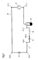
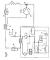
- Fig. 5 schematically shows a schematic diagram of a fiction, according to the invention integrated heat pump system.
- the refrigerant passes under high pressure and temperature in the switching valve 13.
- the operating mode cooling or heating is switched. If the valve 13 is switched to the operating mode cooling, the refrigerant releases heat to the environment via the gas cooler (14) and is further deprived in the high-pressure part of the interior heat exchanger (15).
- the refrigerant in the first expansion valve (16) is expanded to evaporating pressure.
- the operating point is in the 2-phase area. In the evaporator 5, it takes heat from the air flow for the vehicle cabin, which is thereby cooled.
- the second expansion valve (17) is not switched and thus closed.
- the refrigerant flows via the open valve (26) into the collector (19). On the low pressure side of the inner heat exchanger (15), the refrigerant is overheated and then sucked by the compressor (12). In the air box, the air flow for the cabin is cooled, the humidity contained condenses on the cold surfaces of the heat exchanger. If necessary, the air is heated by the heat exchanger 7 accordingly.
- the refrigerant releases the heat via gas cooler / condenser (20) to the air flow for the vehicle cabin.
- the refrigerant After passing through the check valve (10), the refrigerant enters the first expansion valve (16). After appropriate throttling and heat absorption or heat dissipation in the evaporator 5, the refrigerant flows through the second expansion valve 17, in which it is isenthalp relaxed to the evaporation pressure level of heat absorption. In this case, valve 26 is closed.
- heat is supplied from the engine coolant to the refrigerant and optionally superheated.
- the refrigerant flows through the collector 19 and leaves the collector 19 with a defined refrigerant quality, ie ratio of gaseous mass flow to the total mass flow of the refrigerant.
- the refrigerant then flows through the low pressure side of the inner heat exchanger and arrives at Compressor.
- Check valve (6) and (10) are not necessarily required for the function of the heat pump system. You avoid in both cases, that the respective unused circuit part fills with refrigerant. To compensate for this in terms of performance and efficiency, more refrigerant must be added to the system, which is not effective for reasons of environmental protection.
- the air fed into the vehicle cabin is to be dried before heating or the air-side surface of the heat exchanger is wetted with condensate. Drying of the air will always be necessary when the incoming air has a dew point above freezing point. It is particularly expedient to match the evaporation temperature of the refrigerant in this component with the outside temperature in order to ensure the necessary drying in order to safely avoid window fogging without, however, dehumidifying the air for hygienic reasons.
- operation of the air conditioning box in the recirculation mode in winter eg comfort increase during heating or to reduce the pollutant in the cabin no longer a problem.
- the moisture content of the incoming air into the evaporator can by means of humidity sensor, dew point sensor, fog sensor on the windscreen, etc. be determined. Together with the knowledge of the outside temperature can thus be determined a need for drying. With a moisture sensor at a characteristic position on the surface of the evaporator can be determined whether the evaporator is wet. In this case, the evaporator can continue to be operated as an evaporator. The evaporation temperature is either controlled as in the drying or held in the vicinity of the freezing point.
- the first expansion valve 16 is opened a little more and the expansion valve 17 is closed a little more until the evaporation temperature in the evaporator has reached the desired target temperature. Conversely, expansion valve 16 is opened slightly less and expansion valve 17 is opened a little more when the actual evaporator temperature is above the setpoint temperature. The desired compression pressure remains unaffected by this measure, since the total pressure loss through the first expansion valve 16, the evaporator 5 and the second expansion valve 17 remains constant.
- the incoming air is to be preheated in the cabin with the evaporator. This only makes sense if the evaporator has a dry air-side surface. If moisture can be safely avoided by evaporating water through suitable measures, then the expansion valve 16 is fully opened. This heating two heat exchangers in countercurrent with the cabin air in the air box. It can be transmitted very high power.
- the refrigerant inlet temperature into the evaporator 5 is almost equal to the refrigerant outlet temperature at the gas cooler / condenser 20 in the air conditioning box 3.
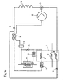
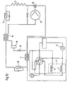
- Fig. 6 schematically shows a schematic diagram of an inventive integrated heat pump system that works with heating with a 2-stage expansion.
- the actual heat absorption of the refrigeration cycle during heating takes place from the outside air.
- the refrigerant passes under high pressure and temperature in the switching valve 13.
- the operating mode cooling or heating is switched. If the valve 13 is switched to the operating mode cooling, the refrigerant releases heat to the environment via the gas cooler (14) and is further deprived in the high-pressure part of the interior heat exchanger (15).
- the refrigerant After passing through the check valve (6), the refrigerant is expanded in the first expansion valve (16) to evaporating pressure.
- the operating point is in the 2-phase area. In the evaporator 5, it takes heat from the air flow for the vehicle cabin, which is thereby cooled.
- the refrigerant flows into the collector (19). On the low pressure side of the inner heat exchanger (15), the refrigerant is overheated and then sucked by the compressor (12). In the air box, the air flow for the cabin is cooled, the humidity contained condenses on the cold surfaces of the heat exchanger. If necessary, the air is heated by the heat exchanger 7 accordingly. If the valve 13 is switched to the operating mode heating, the refrigerant releases the heat via the gas cooler / condenser (20) to the air flow for the vehicle cabin. After passing through the check valve (10), the refrigerant enters the first expansion valve (16).
- the refrigerant flows through the collector 19 and leaves the collector 19 with a defined refrigerant quality then to the low pressure side of the internal heat exchanger.
- the switching valve 21 blocks the direct path to the compressor, thus the second expansion valve 17 is flowed through, in which it is isenthalp relaxed to the evaporation pressure level of the heat absorption.
- the condenser / gas cooler 14 the refrigerant is supplied with heat from the environment and optionally superheated. The refrigerant then passes via the switching valve 21 back to the compressor 12th It is particularly advantageous in this circuit that the engine coolant circuit is not used for heating the cabin during the heating of the vehicle. For heat absorption, a heat exchanger present in the refrigeration cycle is used. Thus, the drive motor heats up quickly, which keeps consumption, wear and emissions low.
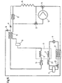
- Fig. 7 schematically shows a schematic diagram of an integrated heat pump system according to the invention.
- the refrigerant passes under high pressure and temperature in the switching valve 13.
- the operating mode cooling or heating is switched. If the valve 13 is switched to the operating mode cooling, the refrigerant releases heat to the environment via the gas cooler (14) and is further deprived in the high-pressure part of the interior heat exchanger (15).
- the refrigerant is expanded in the first expansion valve (16) to evaporating pressure.
- the operating point is in the 2-phase area. In the evaporator 5, it takes heat from the air flow for the vehicle cabin, which is thereby cooled.
- the second expansion valve (17) is not switched and thus closed.
- the refrigerant flows via the open valve (26) into the collector (19). On the Low pressure side of the inner heat exchanger (15), the refrigerant is overheated and then from the compressor. (12) sucked. In the air box, the air flow for the cabin is cooled, the humidity contained condenses on the cold surfaces of the heat exchanger. If necessary, the air is heated by the heat exchanger 7 accordingly.
- the valve 13 is switched to the heating operating mode, the refrigerant releases the heat to the engine coolant via a refrigerant / heat transfer fluid heat exchanger (27). After passing through the check valve (10), the refrigerant enters the first expansion valve (16).
- the refrigerant flows through the second expansion valve 17, in which it is isenthalp relaxed to the evaporation pressure level of heat absorption. In this case, valve 26 is closed.
- the refrigerant / heat transfer fluid heat exchanger 18 heat is supplied to the refrigerant from the engine coolant and optionally superheated.
- the refrigerant flows through the collector 19, the low pressure side of the inner heat exchanger 15 and reaches the compressor 12th
- the transfer of heat in heating mode is done indirectly via the engine coolant.
- the heated engine coolant is conveyed by the heating pump (8) into the heating heat exchanger (7), where it gives off heat to the air flow for the vehicle cabin.
- the engine coolant can flow through further heat exchangers for heat absorption and discharge, such as the exhaust gas recirculation cooler (23). Is the temperature of the engine coolant before entering the engine higher than that of the engine coolant in the engine, or should the engine not be associated with its heating be flowed through, it is via the valve (22) directly to the refrigerant-engine coolant-heat exchanger (27) promoted. If the engine coolant in the engine is warmer than the engine coolant before entering the engine, the engine coolant is routed through the engine to absorb heat. Advantages of such an arrangement result in air-side pressure drop in the air conditioning box by only 2 heat exchangers and the same control of the temperature and air distribution in the cabin during heating operation with the heat pump system and the conventional heating.
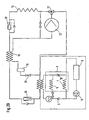
- Fig. 8 is schematically illustrated in a schematic diagram of an integrated heat pump system according to the invention shown operating in heating with a 2-stage expansion. The actual heat absorption of the refrigeration cycle during heating takes place from the outside air.
- the refrigerant After compression, the refrigerant passes under high pressure and temperature in the switching valve 13. Here, the operating mode cooling or heating is switched. If the valve 13 is switched to the operating mode cooling, the refrigerant releases heat to the environment via the gas cooler (14) and is further deprived in the high-pressure part of the interior heat exchanger (15). After passing through the check valve (6), the refrigerant is expanded in the first expansion valve (16) to evaporating pressure. The operating point is in the 2-phase area. In the evaporator 5, it takes heat from the air flow for the vehicle cabin, which is thereby cooled. The refrigerant flows into the collector (19). On the low pressure side of the inner heat exchanger (15), the refrigerant is overheated and then sucked by the compressor (12).
- the air flow for the cabin is cooled, the humidity contained condenses on the cold surfaces of the heat exchanger. If necessary, the air is heated by the heat exchanger 7 accordingly.
- the valve 13 is switched to the heating operating mode, the refrigerant releases the heat to the engine coolant via a refrigerant / engine coolant heat exchanger (27). After passing through the check valve (10), the refrigerant enters the first expansion valve (16). After appropriate throttling and heat absorption or heat dissipation in the evaporator 5, the refrigerant flows through the collector 19 and leaves the collector 19 with a defined refrigerant quality then to the low pressure side of the internal heat exchanger.
- the switching valve 21 blocks the direct path to the compressor, thus the second expansion valve 17 is flowed through, in which it is isenthalp relaxed to the evaporation pressure level of the heat absorption becomes.
- the condenser / gas cooler 14 the refrigerant is supplied with heat from the environment and optionally superheated. The refrigerant then passes via the switching valve 21 back to the compressor 12th It is particularly advantageous in this circuit that the heat absorption of the heat pump takes place from the outside air and thus the engine coolant circuit is heated particularly quickly, which has advantages in consumption, wear and emissions.
- Fig. 9 is shown schematically in an understanding of the invention facilitating schematic diagram of an integrated heat pump system.
- the refrigerant passes under high pressure and temperature in front of the switching valves 24 and 25. If the valve 24 is opened, the refrigerant via the gas cooler (14) heat to the environment and is further in the high pressure part of the interior heat exchanger (15) , After passing through the check valve (6), the refrigerant is expanded in the first expansion valve (16) to evaporating pressure. The operating point is in the 2-phase area. In the evaporator 5, it takes heat from the air flow for the vehicle cabin, which is thereby cooled. The refrigerant flows into the collector (19).
- the refrigerant On the low pressure side of the inner heat exchanger (15), the refrigerant is overheated and then sucked by the compressor (12). In the air box, the air flow for the cabin is cooled, the humidity contained condenses on the cold surfaces of the heat exchanger. If necessary, the air is heated by the heat exchanger 7 accordingly.
- the refrigerant releases the heat to a gas cooler / condenser 20. After passing through the check valve (10), the refrigerant enters the expansion valve 16. After appropriate throttling and heat absorption of the refrigerant circuit in the evaporator 5, the refrigerant flows through the collector 19 and leaves the collector 19 with a defined refrigerant quality on the low pressure side of the internal heat exchanger to the compressor 12th , It is particularly advantageous in this circuit that the heat absorption of the heat pump from the air flow of the cabin air takes place and thus the engine coolant circuit is heated very quickly, which has advantages in consumption, wear and emissions. The heating capacity of this system is limited by the heat extractable from the cabin and the compressor power supplied.
- Fig. 10 is shown schematically in an understanding of the invention facilitating schematic diagram of an integrated heat pump system.
- the refrigerant passes under high pressure and temperature in front of the switching valves 24 and 25. If the valve 24 is opened, the refrigerant via the gas cooler (14) heat to the environment and is further in the high pressure part of the interior heat exchanger (15) , After passing through the check valve (6), the refrigerant is expanded in the first expansion valve (16) to evaporating pressure. The operating point is in the 2-phase area. In the evaporator 5, it takes heat from the air flow for the vehicle cabin, which is thereby cooled. The refrigerant flows into the collector (19).
- the refrigerant On the Low pressure side of the inner heat exchanger (15), the refrigerant is overheated and then sucked by the compressor (12). In the air box, the air flow for the cabin cooled, the humidity contained condenses on the cold surfaces of the heat exchanger. If necessary, the air is heated by the heat exchanger 7 accordingly.
- the valve 25 When the valve 25 is switched, the refrigerant releases the heat to the engine coolant via a refrigerant / engine coolant heat exchanger (27). After passing through the check valve (10), the refrigerant enters the expansion valve 16.
- the refrigerant flows through the collector 19 and leaves the collector 19 with a defined refrigerant quality on the low pressure side of the internal heat exchanger to the compressor 12th , It is particularly advantageous in this circuit that the heat absorption of the heat pump takes place from the air flow of the cabin air and the energy is introduced into the engine coolant circuit. Another benefit arises in the case of cooling. At a start with a heated vehicle interior very large heat fluxes can be discharged into the engine coolant for a short time. As a result, a large cooling capacity is provided. This circuit is always useful when the engine coolant temperature is less than 40 ° C. As a result, the drive motor heats up advantageously.
- FIG 11 shows the circuit Figure 7 with the difference that switching valve 13 has been replaced by two shut-off valves 24 and 25.
- This circuit is always useful when the engine coolant temperature is less than 40 ° C. As a result, the drive motor heats up advantageously.
- Fig. 12 schematically shows a schematic diagram of an integrated heat pump system according to the invention .
- the refrigerant passes under high pressure and temperature in front of the switching valves 24 and 25. If the valve 24 is opened, the refrigerant via the gas cooler (14) heat to the environment and is further in the high pressure part of the interior heat exchanger (15) , After passing through the check valve (6), the refrigerant is expanded in the first expansion valve (16) to evaporating pressure. In the evaporator 5, it takes heat from the air flow for the vehicle cabin, which is thereby cooled. The second expansion valve (17) is not switched and thus closed. The refrigerant flows via the open valve (26) into the collector (19).
- the refrigerant On the low pressure side of the inner heat exchanger (15), the refrigerant is overheated and then sucked by the compressor (12). In the air box, the air flow for the cabin is cooled, the humidity contained condenses on the cold surfaces of the heat exchanger. If necessary, the air is heated by the heat exchanger 7 accordingly.
- the refrigerant releases the heat to a gas cooler / condenser 20.
- the refrigerant enters the expansion valve 16.
- the second expansion valve 17 in which it is isenthalp relaxed to the evaporation pressure level of the heat absorption.
- valve 26 is closed.
- the refrigerant is supplied with heat from the engine coolant and optionally superheated and returned to the compressor 12.
- the collector 19 and the low pressure side of the internal heat exchanger 15 are not flowed through by the circulating refrigerant and communicate with the compressor inlet.
- Fig. 13 schematically shows a schematic diagram of an integrated heat pump system according to the invention, which works with heating with a 2-stage expansion.
- the refrigerant passes under high pressure and temperature before the switching valves 24 and 25. If the valve 24 is open, the refrigerant is on the Gas cooler (14) heat to the environment and is further in the high pressure part of the inner heat exchanger (15) is de-heated. After passing through the check valve (6), the refrigerant is expanded in the first expansion valve (16) to evaporating pressure. The operating point is in the 2-phase area. In the evaporator 5, it takes heat from the air flow for the vehicle cabin, which is thereby cooled. The refrigerant flows into the collector (19).
- the refrigerant On the low pressure side of the inner heat exchanger (15), the refrigerant is overheated and then sucked by the compressor (12). In the air box, the air flow for the cabin is cooled, the humidity contained condenses on the cold surfaces of the heat exchanger. If necessary, the air is heated by the heat exchanger 7 accordingly.
- the valve 25 When the valve 25 is switched, the refrigerant releases the heat to a gas cooler / condenser 20 to the air flow for the vehicle cabin. After passing through the check valve (10), the refrigerant enters the first expansion valve (16).
- the refrigerant flows through the second expansion valve 17, in which it is isenthalp relaxed to the evaporation pressure level of heat absorption.
- the switching valve 26 blocks the way to the collector 19.
- the refrigerant is supplied heat from the environment and optionally superheated. The refrigerant then passes via the switching valve 21 back to the compressor 12th
- the engine coolant circuit is not used for heating the cabin during the heating of the vehicle.
- a heat exchanger present in the refrigeration cycle is used.
- the drive motor heats up quickly, which keeps consumption, wear and emissions low.
- Fig. 14 schematically shows a schematic diagram of an integrated heat pump system according to the invention.
- the refrigerant passes under high pressure and temperature in the switching valve 13.
- the operating mode cooling or heating is switched. If the valve 13 is switched to the operating mode cooling, the refrigerant releases heat to the environment via the gas cooler (14) and is further deprived in the high-pressure part of the interior heat exchanger (15).
- the refrigerant is expanded in the first expansion valve (16) to evaporating pressure.
- the second expansion valve (17) is not switched and thus closed.
- the refrigerant flows via the open valve (26) into the collector (19).
- the refrigerant is overheated and then sucked by the compressor (12).
- the air box the air flow for the cabin is cooled, the humidity contained condenses on the cold surfaces of the heat exchanger. If necessary, the air is heated by the heat exchanger 7 accordingly.
- the refrigerant releases the heat via gas cooler / condenser 20 to the air flow for the vehicle cabin.
- the refrigerant passes to the inlet of the high pressure side of the inner heat exchanger 15 and in succession in the first Expansion valve 16.
- the check valve 6 a subsequent flow of the refrigerant is prevented in the gas cooler 14, in which heat can be dissipated to the environment and the refrigerant contained condenses. In this case, the specific volume increases, which leads to the afterflow of the refrigerant from the circulation.
- the gas cooler fills with liquid refrigerant.
- the refrigerant flows through the second expansion valve 17, in which it is isenthalp relaxed to the evaporation pressure level of heat absorption. In this case, valve 26 is closed.
- the refrigerant / heat transfer fluid heat exchanger 18 heat is supplied from the engine coolant to the refrigerant and optionally superheated.
- the refrigerant flows through the collector 19, the low-pressure side of the interior heat exchanger 15 and reaches the compressor 12. In this circuit, the remaining energy in the refrigerant to overheat the refrigerant before entering the compressor 12 by means of the internal heat exchanger 15 is used. Since some of the energy remains in the circuit so that the suction gas temperatures in the compressor 12 are high, high compressor outlet temperatures are reached. This is the heat at high temperature ready.
- Fig. 15 is shown schematically in a schematic diagram of an integrated heat pump system according to the invention, which works with heating with a 2-stage expansion. The actual heat absorption of the refrigeration cycle during heating takes place from the outside air.
- the refrigerant After compression, the refrigerant passes under high pressure and temperature in the switching valve 13. Here, the operating mode cooling or heating is switched. If the valve 13 is switched to the operating mode cooling, the refrigerant releases heat to the environment via the gas cooler (14) and is further deprived in the high-pressure part of the interior heat exchanger (15). After passing through the check valve (6), the refrigerant is expanded in the first expansion valve (16) to evaporating pressure. In the evaporator 5, it takes heat from the air flow for the vehicle cabin, which is thereby cooled. The refrigerant flows into the collector (19). On the low pressure side of the inner heat exchanger (15), the refrigerant is overheated and then sucked by the compressor (12).
- the air flow for the cabin is cooled, the humidity contained condenses on the cold surfaces of the heat exchanger. If necessary, the air is heated by the heat exchanger 7 accordingly.
- the valve 13 is switched to the heating operating mode, the refrigerant releases the heat to the engine coolant via a refrigerant / engine coolant heat exchanger (27).
- the refrigerant passes to the inlet of the high pressure side of the inner heat exchanger 15 and in succession in the first expansion valve 16.
- the check valve 6 a subsequent flow of the refrigerant is prevented in the gas cooler 14.
- the refrigerant flows through the collector 19 to the low pressure side of the inner heat exchanger 15.
- the switching valve 21 blocks the direct path to the compressor, thus the second expansion valve 17 is flowed through, in which it is enthalpy is relaxed to the evaporation pressure level of heat absorption.
- the condenser / gas cooler 14 the refrigerant is supplied with heat from the environment and optionally superheated. The refrigerant then passes via the switching valve 21 back to the compressor 12th
- Fig. 16 schematically shows a schematic diagram of an integrated heat pump system according to the invention.
- the refrigerant passes under high pressure and temperature in the switching valve 13.
- the operating mode cooling or heating is switched. If the valve 13 is switched to the operating mode cooling, the refrigerant releases heat to the environment via the gas cooler (14) and is further deprived in the high-pressure part of the interior heat exchanger (15).
- the refrigerant is expanded in the first expansion valve (16) to evaporating pressure.
- the second expansion valve (17) is not switched and thus closed.
- the refrigerant flows via the open valve (26) into the collector (19). On the low pressure side of the inner heat exchanger (15), the refrigerant is overheated and then sucked by the compressor (12).
- cooling By switching the switching valve 30 in the operating mode cooling can be cooled in the position of the valve 13 to heating.
- the refrigerant releases a part of the heat via a refrigerant / engine coolant - heat exchanger 27 to the engine coolant and then flows through the switching valve 30 through the check valve 10 in the gas cooler 14. Here, it gives off more heat to the environment and is in the high pressure part of the interior Heat exchanger 15 further deprived.
- the refrigerant in the first Expansion valve 16 relaxed to evaporating pressure.
- the second expansion valve 17 is not switched and thus closed.
- the refrigerant flows via the open valve 26 into the collector 19.
- On the low pressure side of the inner heat exchanger 15, the refrigerant is superheated and then sucked by the compressor 12. In the air box, the air flow for the cabin is cooled, the humidity contained condenses on the cold surfaces of the heat exchanger. If necessary, the air is heated by the heat exchanger 7 accordingly.
- the refrigerant releases the heat to the engine coolant via a refrigerant / engine coolant heat exchanger (27).
- the refrigerant reaches the inlet of the high pressure side of the inner heat exchanger 15 and in succession in the first expansion valve 16.
- the check valve 6 a subsequent flow of the refrigerant is prevented in the gas cooler 14, in which heat to the environment can be dissipated and the refrigerant contained condenses. In this case, the specific volume increases, which leads to the afterflow of the refrigerant from the circulation.
- the gas cooler fills with liquid refrigerant.
- the refrigerant flows through the second expansion valve 17, in which it is isenthalp relaxed to the evaporation pressure level of heat absorption. In this case, valve 26 is closed.
- the refrigerant / heat transfer fluid heat exchanger 18 heat is supplied from the engine coolant to the refrigerant and optionally superheated.
- the refrigerant flows through the collector 19, the low pressure side of the inner heat exchanger 15 and passes to the compressor 12. In this circuit, the energy contained in the refrigerant after compression is introduced into the engine coolant, which thus heats up quickly after driving. This results in advantages in terms of wear, consumption and emission.
- the heat is dissipated not only in the gas cooler but also via the engine radiator. This allows a more efficient heat dissipation.
- the inlet temperature of the refrigerant in the gas cooler is significantly reduced. The temperature is thus below 100 ° C, which represents a major advantage for reasons of strength of the aluminum materials commonly used in heat exchangers.
- Fig. 17 schematically shows a schematic diagram of a heat pump system according to the invention, which allows a 2-stage expansion in the heating mode, indirectly transfers the heat by means of a first heat transfer fluid, the heat for cooling or heating the air indirectly by means of a second heat transfer fluid transfers and heat pump operation, the heat absorbs the air.
- Fig. 18 schematically shows a schematic diagram of an integrated heat pump system according to the invention, which allows a two-stage expansion in the heating mode, the heat indirectly by means of a first heat transfer fluid transfers, the heat for cooling or for heating the air indirectly by means of a transfers second heat transfer fluid and absorbs the heat from the air during heat pump operation.
- Fig. 19 schematically shows in a schematic diagram facilitating the understanding of the invention, an integrated heat pump system that transmits the heat in the heating mode indirectly by means of a first heat transfer fluid, the heat for cooling or heating the air indirectly by means of a second heat transfer fluid and in which the heat from the cooling during cooling Circuit is transferable to the first heat transfer fluid and / or to the outside air.
- Fig. 20 schematically shows a schematic diagram of an integrated heat pump system according to the invention, the heat for cooling or for heating the air indirectly in the coolant circuit of the drive motor or indirectly transmits in a closed subsystem of the coolant circuit and absorbs the heat from the air during heat pump operation.
- Fig. 21 schematically shows a schematic diagram of an integrated heat pump system according to the invention, the heat for cooling or heating of the air indirectly in the coolant circuit of the drive motor or indirectly in a closed subsystem of the coolant circuit transmits and absorbs the heat from the air during heat pump operation and represents the interconnection of the coolant circuit.
- Fig. 22 schematically shows in a schematic diagram an inventive integrated heat pump system, the heat for cooling or for heating the air indirectly in the coolant circuit of the drive motor or indirectly in a closed Subsystem of the refrigerant circuit transmits and heat pump operation absorbs the heat from the air and represents the interconnection of the coolant circuit in a valve unit.
Abstract
Claims (5)
- Système de pompe à chaleur pour un véhicule,◆ dans le cadre duquel un premier échangeur de chaleur (20) d'un circuit d'agent réfrigérant permet de chauffer l'air frais entrant dans l'habitacle du véhicule,◆ un premier dispositif à expansion (16) permet de détendre l'agent réfrigérant d'un niveau de pression intermédiaire supérieur à un niveau de pression intermédiaire approprié et◆ dans le cadre duquel un deuxième échangeur de chaleur (18) permet de capter de la chaleur à partir d'une source de chaleur,caractérisé en ce,◆ qu'un troisième échangeur de chaleur (5) permet de transférer de la chaleur au niveau de pression intermédiaire depuis ou vers l'agent réfrigérant,◆ un deuxième dispositif à expansion (17) permet de détendre l'agent réfrigérant à partir du niveau de pression intermédiaire.
- Système de pompe à chaleur selon la revendication 1, caractérisé en ce que le courant d'air frais intérieur est séché à l'aide de la chaleur amenée au circuit d'agent réfrigérant au niveau de pression intermédiaire.
- Système de pompe à chaleur selon la revendication 1 ou 2, caractérisé en ce qu'un niveau de pression du troisième échangeur de chaleur (5) peut être réglé par une commande correspondante du premier (16) et du deuxième dispositif à expansion (16)
- Système de pompe à chaleur selon la revendication 3, caractérisé en ce que la capacité installée de transfert de chaleur depuis le premier (20) et le troisième échangeur de chaleur (5) correspond à la puissance calorifique maximale du système de pompe à chaleur amenée à l'air frais intérieur.
- Dispositif de pompe à chaleur selon la revendication 3 ou 4, caractérisé en ce que, le premier (20) et/ou le troisième échangeur de chaleur (5) sont réalisés comme des échangeurs de chaleur à fluide caloporteur/agent réfrigérant (27, 3), dans lesquels:◆ un fluide caloporteur est amené dans un deuxième circuit, via lequel◆ de la chaleur peut être transférée du circuit d'agent réfrigérant au courant d'air frais intérieur.
Applications Claiming Priority (3)
| Application Number | Priority Date | Filing Date | Title |
|---|---|---|---|
| DE20121533U | 2001-12-21 | ||
| DE20121533U DE20121533U1 (de) | 2001-12-21 | 2001-12-21 | Aufbau und Regelung einer Klimaanlage für ein Kraftfahrzeug |
| PCT/EP2002/013279 WO2003053726A1 (fr) | 2001-12-21 | 2002-11-26 | Fabrication et regulation d'une climatisation destinee a un vehicule |
Publications (2)
| Publication Number | Publication Date |
|---|---|
| EP1456046A1 EP1456046A1 (fr) | 2004-09-15 |
| EP1456046B1 true EP1456046B1 (fr) | 2008-07-09 |
Family
ID=7965827
Family Applications (1)
| Application Number | Title | Priority Date | Filing Date |
|---|---|---|---|
| EP02805291A Expired - Lifetime EP1456046B1 (fr) | 2001-12-21 | 2002-11-26 | Fabrication et regulation d'une climatisation destinee a un vehicule |
Country Status (6)
| Country | Link |
|---|---|
| US (2) | US7028501B2 (fr) |
| EP (1) | EP1456046B1 (fr) |
| JP (1) | JP4048278B2 (fr) |
| DE (1) | DE50212488D1 (fr) |
| ES (1) | ES2309240T3 (fr) |
| WO (1) | WO2003053726A1 (fr) |
Cited By (1)
| Publication number | Priority date | Publication date | Assignee | Title |
|---|---|---|---|---|
| WO2018166820A1 (fr) | 2017-03-13 | 2018-09-20 | Audi Ag | Installation frigorifique d'un véhicule avec un circuit de réfrigérant pouvant fonctionner comme un circuit frigorifique pour un mode ac et comme circuit de pompe à chaleur pour un mode de chauffage |
Families Citing this family (47)
| Publication number | Priority date | Publication date | Assignee | Title |
|---|---|---|---|---|
| DE10332157A1 (de) * | 2003-06-26 | 2005-01-13 | Behr Gmbh & Co. Kg | Einrichtung zum Kühlen oder zum Erwärmen eines geschlossenen Raumes sowie Verfahren zum Betrieb einer solchen Einrichtung |
| DE602005015120D1 (de) * | 2004-08-18 | 2009-08-06 | Arcelik Anonim Sirketi Tuzla | Kühlvorrichtung |
| KR100688166B1 (ko) * | 2004-12-10 | 2007-03-02 | 엘지전자 주식회사 | 공기조화기 |
| EP1747822A1 (fr) * | 2005-07-28 | 2007-01-31 | Linde Aktiengesellschaft | Système de refroidissement/chauffage pour une machine de nettoyage au dioxyde de carbone |
| JP4600212B2 (ja) * | 2005-08-23 | 2010-12-15 | 株式会社デンソー | 超臨界冷凍サイクル装置 |
| DE102006026359B4 (de) * | 2006-05-31 | 2010-06-17 | Visteon Global Technologies Inc., Van Buren | Klimaanlage für Fahrzeuge |
| JP4785721B2 (ja) * | 2006-12-05 | 2011-10-05 | キヤノン株式会社 | エッチング方法、パターン形成方法、薄膜トランジスタの製造方法及びエッチング液 |
| US20080148748A1 (en) * | 2006-12-21 | 2008-06-26 | Thermo King Corporation | Heating system for transport refrigeration unit |
| US20080289793A1 (en) * | 2007-05-22 | 2008-11-27 | Gerald Geiken | Thermal energy storage systems and methods |
| JP4898556B2 (ja) * | 2007-05-23 | 2012-03-14 | 株式会社日立ハイテクノロジーズ | プラズマ処理装置 |
| DE102007039195B4 (de) * | 2007-08-20 | 2015-03-26 | Ingersoll-Rand Klimasysteme Deutschland Gmbh | Anordnung zum Klimatisieren eines Fahrzeugs |
| JP2009190579A (ja) * | 2008-02-14 | 2009-08-27 | Calsonic Kansei Corp | 空気調和システム |
| ATE479568T1 (de) * | 2008-05-30 | 2010-09-15 | Fiat Group Automobiles Spa | KLIMAANLAGENSYSTEM FÜR EIN KRAFTFAHRZEUG MIT EINEM AN DEN WÄRMESCHALTKREIS ANSCHLIEßBAREN LUFTKÜHLUNGSSCHALTKREIS |
| DE102008028178A1 (de) | 2008-05-30 | 2009-12-03 | Konvekta Ag | Klimaanlage zur Konditionierung mehrerer Fluide |
| SG182572A1 (en) | 2010-01-20 | 2012-08-30 | Carrier Corp | Refrigeration storage in a refrigerant vapor compression system |
| DE102010042127B4 (de) * | 2010-10-07 | 2020-09-17 | Audi Ag | Kältemittelkreislauf einer Klimaanlage eines Kraftfahrzeuges |
| JP2013061099A (ja) * | 2011-09-12 | 2013-04-04 | Toyota Motor Corp | 熱交換装置および熱交換装置の制御方法 |
| DE102011085961A1 (de) * | 2011-11-08 | 2013-05-08 | Behr Gmbh & Co. Kg | Kühlkreislauf |
| US8932483B2 (en) | 2011-11-15 | 2015-01-13 | Ticona Llc | Low naphthenic liquid crystalline polymer composition |
| TWI534253B (zh) | 2011-11-15 | 2016-05-21 | 堤康那責任有限公司 | 具有改良可燃性效能之富含環烷之液晶聚合物組合物 |
| KR101947215B1 (ko) | 2011-11-15 | 2019-02-12 | 티코나 엘엘씨 | 미세 피치 전기 커넥터 및 그에 사용하기 위한 열가소성 조성물 |
| WO2013074469A1 (fr) | 2011-11-15 | 2013-05-23 | Ticona Llc | Module de caméra compact |
| KR101996106B1 (ko) | 2011-11-15 | 2019-07-03 | 티코나 엘엘씨 | 치수 공차가 작은 성형 부품에 사용하기 위한 저-나프텐 액정 중합체 조성물 |
| AU2013259907B2 (en) * | 2012-05-11 | 2017-08-17 | Hill Phoenix, Inc. | CO2 refrigeration system with integrated air conditioning module |
| US9181916B2 (en) * | 2012-07-30 | 2015-11-10 | Ford Global Technologies, Llc | Engine start-stop control strategy for optimization of cabin comfort and fuel economy |
| JP6186998B2 (ja) * | 2013-07-31 | 2017-08-30 | 株式会社デンソー | 車両用空調装置 |
| US10131205B2 (en) * | 2013-08-26 | 2018-11-20 | Ford Global Technologies, Llc | Climate control system |
| US10240825B2 (en) * | 2013-11-13 | 2019-03-26 | Mahle International Gmbh | Evaporator set, preferably for a thermally driven adsorption device, and adsorption device |
| FR3026060B1 (fr) * | 2014-09-23 | 2018-03-23 | Valeo Systemes Thermiques | Circuit de climatisation de vehicule automobile et procede de pilotage correspondant |
| JPWO2016059791A1 (ja) * | 2014-10-17 | 2017-07-27 | パナソニックIpマネジメント株式会社 | 車両用空調装置 |
| JP6007965B2 (ja) * | 2014-12-15 | 2016-10-19 | ダイキン工業株式会社 | 空気調和装置 |
| KR102170463B1 (ko) * | 2015-03-16 | 2020-10-29 | 한온시스템 주식회사 | 차량용 히트 펌프 시스템 |
| JP6078575B2 (ja) * | 2015-03-30 | 2017-02-08 | 富士重工業株式会社 | 車両用エアーコンディショナ装置 |
| US10005339B2 (en) * | 2015-05-26 | 2018-06-26 | GM Global Technology Operations LLC | Vehicle thermal management system and control method for the same |
| DE102015118221A1 (de) * | 2015-10-26 | 2017-04-27 | Hanon Systems | Kältemittelkreislauf für eine Fahrzeugklimaanlage mit Wärmepumpenfunktion |
| JP6481668B2 (ja) | 2015-12-10 | 2019-03-13 | 株式会社デンソー | 冷凍サイクル装置 |
| US20170313435A1 (en) * | 2016-04-29 | 2017-11-02 | Hamilton Sundstrand Corporation | Fuel tank inerting systems for aircraft |
| GB2571111B (en) * | 2018-02-16 | 2020-05-27 | Jaguar Land Rover Ltd | System and method for refrigerant management in an electric vehicle |
| DE102018207049A1 (de) * | 2018-05-07 | 2019-11-07 | Audi Ag | Kälteanlage für ein Fahrzeug mit einem eine Wärmepumpenfunktion aufweisenden Kältemittelkreislauf |
| US11549606B2 (en) * | 2018-11-28 | 2023-01-10 | Mahle International Gmbh | Pilot-pressure-controlled flow valve and fluid system containing same |
| CN111380256A (zh) * | 2018-12-28 | 2020-07-07 | 三花控股集团有限公司 | 热泵系统 |
| FR3097623A1 (fr) * | 2019-06-19 | 2020-12-25 | Valeo Systemes Thermiques | Procédé de contrôle d’un circuit de conditionnement thermique d’un flux d’air |
| DE102019212503A1 (de) * | 2019-08-21 | 2021-02-25 | Audi Ag | Verfahren zum Betreiben einer Kälteanlage für ein Fahrzeug mit einem für einen Kälteanlagen-Betrieb betreibbaren Kältemittelkreislauf |
| US11427053B2 (en) * | 2019-10-17 | 2022-08-30 | Mobile Climate Control, Corp. | Reversible refrigeration cycle system with re-heat capability for use with vehicles |
| DE102019133489A1 (de) * | 2019-12-09 | 2021-06-10 | Audi Ag | Nachheizverfahren zum Betreiben einer Kälteanlage für ein Kraftfahrzeug, Kälteanlage und Kraftfahrzeug mit einer solchen Kälteanlage |
| DE102019133546A1 (de) * | 2019-12-09 | 2021-06-10 | Audi Ag | Nachheizverfahren zum Betreiben einer Kälteanlage für ein Kraftfahrzeug, Kälteanlage und Kraftfahrzeug mit einer solchen Kälteanlage |
| CN112744051A (zh) | 2020-04-02 | 2021-05-04 | 株式会社电装 | 汽车热泵空调系统 |
Family Cites Families (37)
| Publication number | Priority date | Publication date | Assignee | Title |
|---|---|---|---|---|
| US3421339A (en) * | 1967-05-31 | 1969-01-14 | Trane Co | Unidirectional heat pump system |
| US4329206A (en) * | 1980-04-07 | 1982-05-11 | Solar Development Inc. | Alcohol distillation apparatus |
| US4565070A (en) * | 1983-06-01 | 1986-01-21 | Carrier Corporation | Apparatus and method for defrosting a heat exchanger in a refrigeration circuit |
| GB2198223B (en) * | 1986-10-30 | 1990-12-12 | Matsushita Electric Ind Co Ltd | Liquid-gas contactor for non-azeotropic mixture refrigerant |
| DE3730598A1 (de) * | 1987-09-11 | 1989-03-23 | Eberspaecher J | Waermetraegerkreislauf fuer eine fahrzeugheizung mit einem motorunabhaengigen heizgeraet |
| US4850197A (en) * | 1988-10-21 | 1989-07-25 | Thermo King Corporation | Method and apparatus for operating a refrigeration system |
| US5245836A (en) * | 1989-01-09 | 1993-09-21 | Sinvent As | Method and device for high side pressure regulation in transcritical vapor compression cycle |
| DE3907201A1 (de) | 1989-03-07 | 1990-09-13 | Bayerische Motoren Werke Ag | Klimaanlage fuer kraftfahrzeuge mit einem von kuehlen auf heizen umschaltbaren kreislauf |
| US5099651A (en) * | 1989-09-05 | 1992-03-31 | Gas Research Institute | Gas engine driven heat pump method |
| US5228308A (en) * | 1990-11-09 | 1993-07-20 | General Electric Company | Refrigeration system and refrigerant flow control apparatus therefor |
| JP3182773B2 (ja) * | 1991-02-05 | 2001-07-03 | 株式会社デンソー | 自動車用空気調和装置 |
| US5243825A (en) * | 1992-05-05 | 1993-09-14 | Industrial Technology Research Institute | Multi-purpose engine-driven heat pump system |
| DE4318255B4 (de) | 1992-06-13 | 2005-10-06 | Volkswagen Ag | Einrichtung zur Innenraumklimatisierung eines Kraftfahrzeugs |
| JP3433297B2 (ja) * | 1992-12-16 | 2003-08-04 | 株式会社ゼクセルヴァレオクライメートコントロール | 空気調和装置 |
| KR0140503B1 (ko) * | 1993-02-25 | 1997-06-10 | 김광호 | 구획실의 기능을 변경할 수 있는 냉장고 및 그 제어방법 |
| JPH06347111A (ja) * | 1993-06-04 | 1994-12-20 | Zexel Corp | 車両用空調装置の冷暖房サイクル |
| US5641016A (en) * | 1993-12-27 | 1997-06-24 | Nippondenso Co., Ltd. | Air-conditioning apparatus for vehicle use |
| US5410889A (en) * | 1994-01-14 | 1995-05-02 | Thermo King Corporation | Methods and apparatus for operating a refrigeration system |
| JP2677966B2 (ja) * | 1994-02-14 | 1997-11-17 | カルソニック株式会社 | 車両用ヒートポンプ式空気調和装置 |
| DE4432272C2 (de) | 1994-09-09 | 1997-05-15 | Daimler Benz Ag | Verfahren zum Betreiben einer Kälteerzeugungsanlage für das Klimatisieren von Fahrzeugen und eine Kälteerzeugungsanlage zur Durchführung desselben |
| JP3635715B2 (ja) * | 1994-10-07 | 2005-04-06 | 株式会社デンソー | 冷房装置用蒸発器 |
| US5558273A (en) * | 1994-11-10 | 1996-09-24 | Advanced Mechanical Technology, Inc. | Two-pipe system for refrigerant isolation |
| US5596878A (en) * | 1995-06-26 | 1997-01-28 | Thermo King Corporation | Methods and apparatus for operating a refrigeration unit |
| JPH0939542A (ja) * | 1995-08-02 | 1997-02-10 | Matsushita Electric Ind Co Ltd | 電気自動車用ヒートポンプ冷暖房除湿装置 |
| JP3799748B2 (ja) * | 1996-08-06 | 2006-07-19 | 株式会社デンソー | 車両用空調装置 |
| DE69734308T2 (de) * | 1996-11-15 | 2006-06-14 | Calsonic Kansei Corp | Fahrzeugklimaanlage |
| JP3781147B2 (ja) * | 1997-04-09 | 2006-05-31 | カルソニックカンセイ株式会社 | ヒートポンプ式自動車用空気調和装置 |
| JP3847905B2 (ja) * | 1997-06-30 | 2006-11-22 | カルソニックカンセイ株式会社 | ヒートポンプ式自動車用空気調和装置 |
| US6058727A (en) * | 1997-12-19 | 2000-05-09 | Carrier Corporation | Refrigeration system with integrated oil cooling heat exchanger |
| DE19813674C1 (de) | 1998-03-27 | 1999-04-15 | Daimler Chrysler Ag | Vorrichtung und Verfahren zum Heizen und Kühlen eines Nutzraumes eines Kraftfahrzeuges |
| FR2779215B1 (fr) * | 1998-05-28 | 2000-08-04 | Valeo Climatisation | Circuit de climatisation utilisant un fluide refrigerant a l'etat supercritique, notamment pour vehicule |
| FR2779216B1 (fr) * | 1998-05-28 | 2000-08-04 | Valeo Climatisation | Dispositif de climatisation de vehicule utilisant un fluide refrigerant a l'etat supercritique |
| JP3985384B2 (ja) | 1998-09-24 | 2007-10-03 | 株式会社デンソー | 冷凍サイクル装置 |
| JP2000274838A (ja) * | 1999-03-25 | 2000-10-06 | Tgk Co Ltd | バイパス管路付冷凍サイクル |
| FR2806039B1 (fr) * | 2000-03-10 | 2002-09-06 | Valeo Climatisation | Dispositif de climatisation de vehicule comportant un echangeur de chaleur polyvalent |
| JP3576092B2 (ja) * | 2000-11-10 | 2004-10-13 | 松下冷機株式会社 | 冷蔵庫 |
| DE10128164A1 (de) * | 2001-06-09 | 2002-12-12 | Behr Gmbh & Co | Fahrzeug-Kühlsystem für eine temperaturerhöhende Einrichtung sowie Verfahren zur Kühlung der temperaturerhöhenden Einrichtung |
-
2002
- 2002-11-26 WO PCT/EP2002/013279 patent/WO2003053726A1/fr active IP Right Grant
- 2002-11-26 JP JP2003554464A patent/JP4048278B2/ja not_active Expired - Lifetime
- 2002-11-26 EP EP02805291A patent/EP1456046B1/fr not_active Expired - Lifetime
- 2002-11-26 ES ES02805291T patent/ES2309240T3/es not_active Expired - Lifetime
- 2002-11-26 DE DE50212488T patent/DE50212488D1/de not_active Expired - Lifetime
-
2004
- 2004-06-21 US US10/871,508 patent/US7028501B2/en not_active Expired - Lifetime
-
2006
- 2006-01-31 US US11/344,724 patent/US7231776B2/en active Active
Cited By (3)
| Publication number | Priority date | Publication date | Assignee | Title |
|---|---|---|---|---|
| WO2018166820A1 (fr) | 2017-03-13 | 2018-09-20 | Audi Ag | Installation frigorifique d'un véhicule avec un circuit de réfrigérant pouvant fonctionner comme un circuit frigorifique pour un mode ac et comme circuit de pompe à chaleur pour un mode de chauffage |
| DE102017204116B4 (de) | 2017-03-13 | 2022-06-15 | Audi Ag | Kälteanlage eines Fahrzeugs mit einem als Kältekreislauf für einen Kältebetrieb und als Wärmepumpenkreislauf für einen Heizbetrieb betreibbaren Kältemittelkreislauf |
| US11884134B2 (en) | 2017-03-13 | 2024-01-30 | Audi Ag | Cooling system of a vehicle, comprising a coolant circuit which can be operated as a cooling circuit for an AC operation and as a heat pump circuit for a heating operation |
Also Published As
| Publication number | Publication date |
|---|---|
| JP2005512869A (ja) | 2005-05-12 |
| JP4048278B2 (ja) | 2008-02-20 |
| US7028501B2 (en) | 2006-04-18 |
| US20060123824A1 (en) | 2006-06-15 |
| EP1456046A1 (fr) | 2004-09-15 |
| DE50212488D1 (de) | 2008-08-21 |
| US7231776B2 (en) | 2007-06-19 |
| US20050034473A1 (en) | 2005-02-17 |
| ES2309240T3 (es) | 2008-12-16 |
| WO2003053726A1 (fr) | 2003-07-03 |
Similar Documents
| Publication | Publication Date | Title |
|---|---|---|
| EP1456046B1 (fr) | Fabrication et regulation d'une climatisation destinee a un vehicule | |
| DE10163607A1 (de) | Aufbau und Regelung einer Klimaanlage für ein Kraftfahrzeug | |
| EP1262347B1 (fr) | Circuit de chauffage/réfrigération pour un climatiseur de véhicule à moteur, climatiseur et procédé pour sa commande | |
| DE10253357B4 (de) | Kombinierte Kälteanlage/Wärmepumpe zum Einsatz in Kraftfahrzeugen zum Kühlen, Heizen und Entfeuchten des Fahrzeuginnenraumes | |
| EP1264715B2 (fr) | Système de refroidissement d'un véhicule pour un dispositif d'augmentation de la température et méthode pour le refroidissement du dispositif d'augmentation de la température | |
| DE102019207203A1 (de) | Wärmepumpensystem für fahrzeuge | |
| EP1467879B1 (fr) | Circuit de chauffage/refroidissement pour systeme de climatisation d'automobile, systeme de climatisation et procede pour le reguler | |
| DE102006024796B4 (de) | Klimaanlage | |
| EP1338449B1 (fr) | Système de climatisation de véhicule, en particulier système de climatisation à CO2 | |
| DE112016003558B4 (de) | Wärmepumpen-System | |
| DE102012111672B4 (de) | Kältemittelkreislauf einer Klimaanlage mit Wärmepumpen- und Nachheizfunktionalität | |
| DE102013110224A1 (de) | Verfahren zum Betreiben einer Klimaanlage für ein Kraftfahrzeug | |
| WO2002092368A1 (fr) | Installation de climatisation | |
| DE112013003304T5 (de) | Fahrzeugklimaanlageneinheit | |
| EP1499511A1 (fr) | Installation de climatisation | |
| DE112020004318T5 (de) | Anschlussmodul | |
| EP1472106B1 (fr) | Installation de climatisation ayant une fonction chauffage et son mode de fonctionnement | |
| WO2019214927A1 (fr) | Système de refroidissement d'un véhicule, muni d'un circuit de fluide réfrigérant présentant une fonction de pompe à chaleur | |
| DE102018122675A1 (de) | Thermisches System eines Kraftfahrzeugs und Verfahren zum Betreiben des thermischen Systems | |
| DE102005005430A1 (de) | Verfahren zum Betreiben einer Klimaanlage | |
| DE10245257A1 (de) | Wärmemanagementvorrichtung für ein Kraftfahrzeug | |
| DE602005001770T2 (de) | Klimaanlage | |
| EP1572478B1 (fr) | Procede pour climatiser un vehicule automobile | |
| DE102022208050A1 (de) | Verfahren zum Steuern eines Fahrzeug-HLK-Systems | |
| WO2023280507A1 (fr) | Circuit de réfrigération ainsi que système de gestion thermique et véhicule motorisé comportant un circuit de réfrigération de ce type |
Legal Events
| Date | Code | Title | Description |
|---|---|---|---|
| PUAI | Public reference made under article 153(3) epc to a published international application that has entered the european phase |
Free format text: ORIGINAL CODE: 0009012 |
|
| 17P | Request for examination filed |
Effective date: 20040604 |
|
| AK | Designated contracting states |
Kind code of ref document: A1 Designated state(s): AT BE BG CH CY CZ DE DK EE ES FI FR GB GR IE IT LI LU MC NL PT SE SK TR |
|
| RAP1 | Party data changed (applicant data changed or rights of an application transferred) |
Owner name: DAIMLERCHRYSLER AG |
|
| 17Q | First examination report despatched |
Effective date: 20071022 |
|
| RAP1 | Party data changed (applicant data changed or rights of an application transferred) |
Owner name: DAIMLER AG |
|
| GRAP | Despatch of communication of intention to grant a patent |
Free format text: ORIGINAL CODE: EPIDOSNIGR1 |
|
| GRAS | Grant fee paid |
Free format text: ORIGINAL CODE: EPIDOSNIGR3 |
|
| GRAA | (expected) grant |
Free format text: ORIGINAL CODE: 0009210 |
|
| AK | Designated contracting states |
Kind code of ref document: B1 Designated state(s): DE ES FR GB IT SE |
|
| REG | Reference to a national code |
Ref country code: GB Ref legal event code: FG4D Free format text: NOT ENGLISH |
|
| REF | Corresponds to: |
Ref document number: 50212488 Country of ref document: DE Date of ref document: 20080821 Kind code of ref document: P |
|
| REG | Reference to a national code |
Ref country code: SE Ref legal event code: TRGR |
|
| REG | Reference to a national code |
Ref country code: ES Ref legal event code: FG2A Ref document number: 2309240 Country of ref document: ES Kind code of ref document: T3 |
|
| PLBE | No opposition filed within time limit |
Free format text: ORIGINAL CODE: 0009261 |
|
| STAA | Information on the status of an ep patent application or granted ep patent |
Free format text: STATUS: NO OPPOSITION FILED WITHIN TIME LIMIT |
|
| 26N | No opposition filed |
Effective date: 20090414 |
|
| REG | Reference to a national code |
Ref country code: GB Ref legal event code: 732E Free format text: REGISTERED BETWEEN 20140116 AND 20140122 |
|
| REG | Reference to a national code |
Ref country code: FR Ref legal event code: TP Owner name: HALLA VISTEON CLIMATE CONTROL CORPORATION, KR Effective date: 20140206 |
|
| REG | Reference to a national code |
Ref country code: ES Ref legal event code: PC2A Owner name: HALLA VISTEON CLIMATE CONTROL CORPORATION Effective date: 20140310 |
|
| REG | Reference to a national code |
Ref country code: DE Ref legal event code: R082 Ref document number: 50212488 Country of ref document: DE Representative=s name: SPERLING, FISCHER & HEYNER PATENTANWAELTE, DE |
|
| REG | Reference to a national code |
Ref country code: DE Ref legal event code: R082 Ref document number: 50212488 Country of ref document: DE Representative=s name: SPERLING, FISCHER & HEYNER PATENTANWAELTE, DE Effective date: 20140721 Ref country code: DE Ref legal event code: R081 Ref document number: 50212488 Country of ref document: DE Owner name: HALLA VISTEON CLIMATE CONTROL CORPORATION, KR Free format text: FORMER OWNER: DAIMLER AG, 70327 STUTTGART, DE Effective date: 20140721 |
|
| REG | Reference to a national code |
Ref country code: FR Ref legal event code: PLFP Year of fee payment: 14 |
|
| REG | Reference to a national code |
Ref country code: ES Ref legal event code: PC2A Owner name: HANON SYSTEMS Effective date: 20160401 |
|
| REG | Reference to a national code |
Ref country code: FR Ref legal event code: PLFP Year of fee payment: 15 |
|
| REG | Reference to a national code |
Ref country code: FR Ref legal event code: CD Owner name: HANON SYSTEMS Effective date: 20161212 |
|
| REG | Reference to a national code |
Ref country code: FR Ref legal event code: PLFP Year of fee payment: 16 |
|
| REG | Reference to a national code |
Ref country code: FR Ref legal event code: PLFP Year of fee payment: 17 |
|
| PGFP | Annual fee paid to national office [announced via postgrant information from national office to epo] |
Ref country code: GB Payment date: 20211014 Year of fee payment: 20 Ref country code: ES Payment date: 20211203 Year of fee payment: 20 Ref country code: FR Payment date: 20211109 Year of fee payment: 20 Ref country code: DE Payment date: 20211012 Year of fee payment: 20 Ref country code: SE Payment date: 20211027 Year of fee payment: 20 |
|
| PGFP | Annual fee paid to national office [announced via postgrant information from national office to epo] |
Ref country code: IT Payment date: 20211027 Year of fee payment: 20 |
|
| REG | Reference to a national code |
Ref country code: DE Ref legal event code: R071 Ref document number: 50212488 Country of ref document: DE |
|
| REG | Reference to a national code |
Ref country code: GB Ref legal event code: PE20 Expiry date: 20221125 |
|
| REG | Reference to a national code |
Ref country code: SE Ref legal event code: EUG |
|
| PG25 | Lapsed in a contracting state [announced via postgrant information from national office to epo] |
Ref country code: GB Free format text: LAPSE BECAUSE OF EXPIRATION OF PROTECTION Effective date: 20221125 |
|
| REG | Reference to a national code |
Ref country code: ES Ref legal event code: FD2A Effective date: 20230428 |
|
| PG25 | Lapsed in a contracting state [announced via postgrant information from national office to epo] |
Ref country code: ES Free format text: LAPSE BECAUSE OF EXPIRATION OF PROTECTION Effective date: 20221127 |