EP1455883B1 - Guidewire distal tip soldering method and manufacturing assembly - Google Patents
Guidewire distal tip soldering method and manufacturing assembly Download PDFInfo
- Publication number
- EP1455883B1 EP1455883B1 EP02804439A EP02804439A EP1455883B1 EP 1455883 B1 EP1455883 B1 EP 1455883B1 EP 02804439 A EP02804439 A EP 02804439A EP 02804439 A EP02804439 A EP 02804439A EP 1455883 B1 EP1455883 B1 EP 1455883B1
- Authority
- EP
- European Patent Office
- Prior art keywords
- shaft
- guidewire
- solder ball
- accordance
- flux
- Prior art date
- Legal status (The legal status is an assumption and is not a legal conclusion. Google has not performed a legal analysis and makes no representation as to the accuracy of the status listed.)
- Expired - Lifetime
Links
Images
Classifications
-
- B—PERFORMING OPERATIONS; TRANSPORTING
- B21—MECHANICAL METAL-WORKING WITHOUT ESSENTIALLY REMOVING MATERIAL; PUNCHING METAL
- B21F—WORKING OR PROCESSING OF METAL WIRE
- B21F15/00—Connecting wire to wire or other metallic material or objects; Connecting parts by means of wire
- B21F15/02—Connecting wire to wire or other metallic material or objects; Connecting parts by means of wire wire with wire
- B21F15/06—Connecting wire to wire or other metallic material or objects; Connecting parts by means of wire wire with wire with additional connecting elements or material
- B21F15/08—Connecting wire to wire or other metallic material or objects; Connecting parts by means of wire wire with wire with additional connecting elements or material making use of soldering or welding
-
- A—HUMAN NECESSITIES
- A61—MEDICAL OR VETERINARY SCIENCE; HYGIENE
- A61M—DEVICES FOR INTRODUCING MEDIA INTO, OR ONTO, THE BODY; DEVICES FOR TRANSDUCING BODY MEDIA OR FOR TAKING MEDIA FROM THE BODY; DEVICES FOR PRODUCING OR ENDING SLEEP OR STUPOR
- A61M25/00—Catheters; Hollow probes
- A61M25/01—Introducing, guiding, advancing, emplacing or holding catheters
- A61M25/09—Guide wires
- A61M2025/09058—Basic structures of guide wires
- A61M2025/09083—Basic structures of guide wires having a coil around a core
-
- A—HUMAN NECESSITIES
- A61—MEDICAL OR VETERINARY SCIENCE; HYGIENE
- A61M—DEVICES FOR INTRODUCING MEDIA INTO, OR ONTO, THE BODY; DEVICES FOR TRANSDUCING BODY MEDIA OR FOR TAKING MEDIA FROM THE BODY; DEVICES FOR PRODUCING OR ENDING SLEEP OR STUPOR
- A61M25/00—Catheters; Hollow probes
- A61M25/01—Introducing, guiding, advancing, emplacing or holding catheters
- A61M25/09—Guide wires
- A61M2025/09108—Methods for making a guide wire
-
- A—HUMAN NECESSITIES
- A61—MEDICAL OR VETERINARY SCIENCE; HYGIENE
- A61M—DEVICES FOR INTRODUCING MEDIA INTO, OR ONTO, THE BODY; DEVICES FOR TRANSDUCING BODY MEDIA OR FOR TAKING MEDIA FROM THE BODY; DEVICES FOR PRODUCING OR ENDING SLEEP OR STUPOR
- A61M25/00—Catheters; Hollow probes
- A61M25/01—Introducing, guiding, advancing, emplacing or holding catheters
- A61M25/09—Guide wires
- A61M2025/09175—Guide wires having specific characteristics at the distal tip
Definitions
- the present invention pertains to guidewires for use with intravascular catheters. More particularly, the present invention pertains to guidewires with an improved, atraumatic distal tip.
- intravascular catheters have become an effective method for treating many types of vascular disease.
- an intravascular catheter is inserted into the vascular system of the patient and navigated through the vasculature to a desired target site.
- a desired target site in the patient's vascular system may be accessed, including the coronary, cerebral, and peripheral vasculature.
- therapeutic purposes for intravascular catheters include percutaneous transluminal angioplasty (PTA) and percutaneous transluminal coronary angioplasty (PTCA).
- Intravascular catheters are commonly used in conjunction with a guidewire.
- a guidewire may be advanced through the patient's vasculature until it has reached a target location. Once in place, a catheter may be threaded onto the guidewire and urged distally until the distal end of the catheter reaches a target location.
- the vasculature of a human being can be a very tortuous path.
- the distal tip of the guidewire may be tapered.
- a coil may be disposed about the guidewire, for example to provide support and/or strength. It may be desirable for the coil to be secured to the guidewire. This may be accomplished by welding a portion of the coil to the inner core member of the guidewire. Welding may require the use of a heat sink to help absorb some of the heat generated during welding. Following welding, the heat sink may be removed by grinding. Grinding may also serve to smooth the distal tip.
- a guidewire manufacturing assembly as described in the preamble of claim 1 and a method of forming an atraumatic distal tip on a guidewire as described in the preamble of claim 9 is disclosed in US-A-5458585.
- the present invention as described in claim 1 and claim 9 pertains to a refinement of guidewires. More particularly, the present invention pertains to guidewires with an improved distal tip.
- the distal tip may include an atraumatic solder tip.
- the atraumatic tip may help to secure a coil to the inner shaft of the guidewire.
- the atraumatic tip may be formed by performing a minimal amount of processing steps.
- the guidewire includes an inner elongate shaft having a coil disposed along at least a portion of its length.
- a solder ball is disposed at the distal end of the shaft and a quantity of flux may be disposed proximate the solder ball.
- a heat source is disposed proximate the solder ball for heating the solder ball to a temperature where at least a portion of the solder ball is melted. Heating the solder ball may activate the flux and resultsin flow of molten solder proximally. Solder remaining at the distal end of the shaft may form the atraumatic distal tip.
- a holding fixture is coupled to the shaft that may comprise a heat sink to draw away or absorb heat.
- a heat shrink tube may also be coupled to the shaft to stop proximal migration of flux and/or solder.
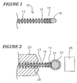
- Figure 1 is a cross-sectional view of a guidewire with an atraumatic distal tip
- Figure 2 is a plan view of the guidewire wherein a holding fixture and a heat shrink tube are coupled to the shaft.
- FIG. 1 is a cross-sectional view of a guidewire with an atraumatic distal tip.
- a guidewire 10 comprises an elongate shaft 12 having a distal end 14, a coil 16, and an atraumatic distal tip 18.
- Atraumatic distal tip 18 is formed by partially melting a solder ball 22 that is dipped in or otherwise coupled to a quantity of flux 24. A portion of the partially molten solder ball 22 migrates proximally along shaft 12 when heated, leaving behind distal tip 18 at distal end 14. Proximal flow of solder ball 22 serves the function of coupling coil 16 to shaft 12.
- Tip 18 has a generally smooth texture and rounded shape. Moreover, the shape and texture of tip 18 may result without any additional steps of grinding, filing, or smoothing.
- the method of forming atraumatic distal tip 18 may also include the use of a heat sink (described below) to draw heat away from guidewire 10. By drawing heat away from guidewire 10, localized heat effected areas that may weaken the strength of guidewire 10 may be minimized.
- Shaft 12 may be comprised of materials including, but not limited to, metals, stainless steel, nickel alloys, nickel-titanium alloys, thermoplastics, high performance engineering resins, fluorinated ethylene propylene (FEP), polymer, polyethylene (PE), polypropylene (PP), polyvinylchloride (PVC), polyurethane, polytetrafluoroethylene (PTFE), polyether block amide (PEBA), polyether-ether ketone (PEEK), polyimide, polyamide, polyphenylene sulfide (PPS), polyphenylene oxide (PPO), polysufone, nylon, perfluoro(propyl vinyl ether) (PFA), and combinations thereof.
- FEP fluorinated ethylene propylene
- PE polyethylene
- PP polypropylene
- PVC polyvinylchloride
- PVC polyurethane
- PTFE polytetrafluoroethylene
- PEBA polyether block amide
- PEEK polyether-
- Shaft 12 may be distally tapered.
- shaft 12 may further comprise a plurality of distal segments or comprise a single, generally tapered distal end 14.
- Each distal segment may comprise a decreased outside diameter or individual segments may each taper along the length of a particular segment.
- Coil 16 may be comprised of materials similar to those listed above.
- coil 16 may be comprised of a stainless steel wire
- coil 16 may have an outside diameter of about, for example, 0.051 to 0,076 mm (0.002 to 0.0030 inches) and be disposed about shaft 12 with a pitch of about, for example, 0.061 to 0.081 mm (0.0024 to 0.0032 inches) per turn.
- a portion of coil 16 may be comprised of radiopaque materials.
- a radiopaque coil is understood to be capable of producing a relatively bright image on a fluoroscopy screen or another imaging technique during a medical procedure. This relatively bright image aids the user of guidewire 10 in determining the location of distal end 14 of shaft 12.
- Radiopaque materials may include, but are not limited to, gold, platinum, tungsten alloy, and plastic material loaded with a radiopaque filler.
- Guidewire 10 may further comprise additional radiopaque markers.
- coil 16, alternatively, may comprise a plurality of coils. According to this embodiment, an individual segment of coil 16 may be comprised of radiopaque materials.
- FIG. 2 is a plan view of guidewire 10 wherein a holding fixture 20 is coupled to shaft 12.
- Holding fixture 20 may comprise a heat sink.
- a heat sink is understood to be a structure that substantially absorbs heat from a given location.
- Holding fixture 20 may be used to hold guidewire 10 stationary during the formation of atraumatic distal tip 18.
- Holding fixture 20 may be used with guidewire 10 in a horizontal or a vertical orientation.
- Solder ball 22 may be coupled to distal end 14 of elongate shaft 12. Solder ball 22 may be used to form atraumatic tip 18. Solder ball 22 may be radiopaque and useful for imaging guidewire 10. In addition, solder ball 22 may have an outside diameter of about 0.30 to 0.51 mm (0.012 to 0.020 inches). Solder ball 22 can be generally spherical in shape. A person of ordinary skill in the art would be familiar with different sizes and shapes of solder ball 22 that may be appropriate for multiple embodiments of the invention.
- Solder ball 22 is coupled to a quantity of flux 24.
- Flux 24 is understood to be a substance applied to parts of a surface or surfaces to be joined, acting on application of heat to prevent oxide formation and facilitate the flowing of solder.
- Solder ball 22 may be coupled to flux 24, for example, by dipping solder ball 22 into flux 24.
- Flux 24 may be used to couple solder ball 22 to distal end 14 of elongate shaft 12. Distal end 14 of shaft 12 may be aligned flush with an end of coil 16.
- flux 24 may have a surface tension that may secure solder ball 22 to distal end 14 of elongate shaft 12.
- flux 24 may include adhesive properties that may assist the coupling of solder ball 22 to shaft 12.
- a heat source 26 is disposed proximate solder ball 22. It should be understood that multiple locations of heat source 26 relative to solder ball 22 may be used without departing from the scope of the invention, for example behind or under solder ball 22. Heat source 26 is capable of increasing the temperature of solder ball 22 such that at least a portion thereof melts. For example, heat source 26 may have a temperature of about 460°C. Alternatively, heat source 26 may have a temperature up to about, for example, 600°C or greater.
- the heat cycle time that solder ball 22 is exposed to heat source 26 may also very. For example, the cycle time of exposure may be up to about 5 seconds or more.
- Heat source 26 may be used to form atraumatic distal tip 18. Heating may activate flux 24 and allows solder ball 22 to at least partially melt and flow into coil 16 and around shaft 12. Atraumatic tip 18 may be formed by solder remaining at distal end 14 of shaft 12 after heating. After heating, little or no flux 24 will remain due to flux 24 being incinerated. In an exemplary embodiment, additional processing of guidewire 10 may not be required such as grinding, filing, smoothing, etc.
- flux 24 migrates proximally along shaft 12.
- the proximal migration of flux 24 may contribute to the size and shape of atraumatic distal tip 18 since migration of flux 24 may facilitate the flow of solder.
- a greater quantity of molten solder i.e., from solder ball 22
- the greater the quantity of solder that is allowed to flow proximally the smaller the quantity of solder remaining at distal end 14 of shaft 12 for the formation of atraumatic distal tip 18.
- Holding fixture 20, therefore, may be positioned along shaft 12 so as to prevent flux 24 from migrating too far proximally and altering the formation of atraumatic distal tip 18.
- Guidewire 10 may further comprise a heat shrink tube 28 coupled to shaft 12.
- Heat shrink tube 28 may be used to prevent proximal migration of flux 24 similar to what is described above and may provide a barrier to prevention of proximal migration of flux 24.
- Heat shrink tube 28. may be comprised of polytetrafluoroethylene and coupled to shaft 12. Heat shrink tube 28 may remain coupled to shaft 12 after manufacturing of guidewire 10 or may be removed after manufacturing.
Abstract
Description
- The present invention pertains to guidewires for use with intravascular catheters. More particularly, the present invention pertains to guidewires with an improved, atraumatic distal tip.
- The use of intravascular catheters has become an effective method for treating many types of vascular disease. In general, an intravascular catheter is inserted into the vascular system of the patient and navigated through the vasculature to a desired target site. Using this method, virtually any target site in the patient's vascular system may be accessed, including the coronary, cerebral, and peripheral vasculature. Examples of therapeutic purposes for intravascular catheters include percutaneous transluminal angioplasty (PTA) and percutaneous transluminal coronary angioplasty (PTCA).
- Intravascular catheters are commonly used in conjunction with a guidewire. A guidewire may be advanced through the patient's vasculature until it has reached a target location. Once in place, a catheter may be threaded onto the guidewire and urged distally until the distal end of the catheter reaches a target location.
- The vasculature of a human being can be a very tortuous path. In order for a guidewire to be steered through the vasculature, it may be beneficial for the guidewire to be flexible, particularly near the distal end. Increased flexibility may be incorporated into a guidewire in a number of differing ways. For example, the distal tip of the guidewire may be tapered.
- A coil may be disposed about the guidewire, for example to provide support and/or strength. It may be desirable for the coil to be secured to the guidewire. This may be accomplished by welding a portion of the coil to the inner core member of the guidewire. Welding may require the use of a heat sink to help absorb some of the heat generated during welding. Following welding, the heat sink may be removed by grinding. Grinding may also serve to smooth the distal tip.
- A guidewire manufacturing assembly as described in the preamble of claim 1 and a method of forming an atraumatic distal tip on a guidewire as described in the preamble of claim 9 is disclosed in US-A-5458585.
- The present invention as described in claim 1 and claim 9 pertains to a refinement of guidewires. More particularly, the present invention pertains to guidewires with an improved distal tip. The distal tip may include an atraumatic solder tip. The atraumatic tip may help to secure a coil to the inner shaft of the guidewire. Moreover, the atraumatic tip may be formed by performing a minimal amount of processing steps.
- The guidewire includes an inner elongate shaft having a coil disposed along at least a portion of its length. A solder ball is disposed at the distal end of the shaft and a quantity of flux may be disposed proximate the solder ball. A heat source is disposed proximate the solder ball for heating the solder ball to a temperature where at least a portion of the solder ball is melted. Heating the solder ball may activate the flux and resultsin flow of molten solder proximally. Solder remaining at the distal end of the shaft may form the atraumatic distal tip. A holding fixture is coupled to the shaft that may comprise a heat sink to draw away or absorb heat. A heat shrink tube may also be coupled to the shaft to stop proximal migration of flux and/or solder.
- Figure 1 is a cross-sectional view of a guidewire with an atraumatic distal tip; and
- Figure 2 is a plan view of the guidewire wherein a holding fixture and a heat shrink tube are coupled to the shaft.
- The following description should be read with reference to the drawings wherein like reference numerals indicate like elements throughout the several views. The detailed description and drawings illustrate example embodiments of the claimed invention.
- Figure 1 is a cross-sectional view of a guidewire with an atraumatic distal tip. A
guidewire 10 comprises anelongate shaft 12 having adistal end 14, acoil 16, and an atraumaticdistal tip 18. Atraumaticdistal tip 18 is formed by partially melting asolder ball 22 that is dipped in or otherwise coupled to a quantity offlux 24. A portion of the partiallymolten solder ball 22 migrates proximally alongshaft 12 when heated, leaving behinddistal tip 18 atdistal end 14. Proximal flow ofsolder ball 22 serves the function ofcoupling coil 16 toshaft 12. -
Tip 18 has a generally smooth texture and rounded shape. Moreover, the shape and texture oftip 18 may result without any additional steps of grinding, filing, or smoothing. The method of formingatraumatic distal tip 18 may also include the use of a heat sink (described below) to draw heat away fromguidewire 10. By drawing heat away fromguidewire 10, localized heat effected areas that may weaken the strength ofguidewire 10 may be minimized. -
Shaft 12 may be comprised of materials including, but not limited to, metals, stainless steel, nickel alloys, nickel-titanium alloys, thermoplastics, high performance engineering resins, fluorinated ethylene propylene (FEP), polymer, polyethylene (PE), polypropylene (PP), polyvinylchloride (PVC), polyurethane, polytetrafluoroethylene (PTFE), polyether block amide (PEBA), polyether-ether ketone (PEEK), polyimide, polyamide, polyphenylene sulfide (PPS), polyphenylene oxide (PPO), polysufone, nylon, perfluoro(propyl vinyl ether) (PFA), and combinations thereof. - Shaft 12 may be distally tapered. According to this embodiment,
shaft 12 may further comprise a plurality of distal segments or comprise a single, generally tapereddistal end 14. Each distal segment may comprise a decreased outside diameter or individual segments may each taper along the length of a particular segment. A person of ordinary skill in the art could appreciate that a vast number of alternate configurations of segments and distal ends may be included without departing from the scope of the invention. -
Coil 16 may be comprised of materials similar to those listed above. For example,coil 16 may be comprised of a stainless steel wire According to this embodiment,coil 16 may have an outside diameter of about, for example, 0.051 to 0,076 mm (0.002 to 0.0030 inches) and be disposed aboutshaft 12 with a pitch of about, for example, 0.061 to 0.081 mm (0.0024 to 0.0032 inches) per turn. - In addition, a portion of
coil 16 may be comprised of radiopaque materials. A radiopaque coil is understood to be capable of producing a relatively bright image on a fluoroscopy screen or another imaging technique during a medical procedure. This relatively bright image aids the user ofguidewire 10 in determining the location ofdistal end 14 ofshaft 12. Radiopaque materials may include, but are not limited to, gold, platinum, tungsten alloy, and plastic material loaded with a radiopaque filler. Guidewire 10 may further comprise additional radiopaque markers. It should be understood thatcoil 16, alternatively, may comprise a plurality of coils. According to this embodiment, an individual segment ofcoil 16 may be comprised of radiopaque materials. - Figure 2 is a plan view of
guidewire 10 wherein a holdingfixture 20 is coupled toshaft 12. Holdingfixture 20 may comprise a heat sink. A heat sink is understood to be a structure that substantially absorbs heat from a given location. Holdingfixture 20 may be used to holdguidewire 10 stationary during the formation of atraumaticdistal tip 18. Holdingfixture 20 may be used withguidewire 10 in a horizontal or a vertical orientation. -
Solder ball 22 may be coupled todistal end 14 ofelongate shaft 12.Solder ball 22 may be used to formatraumatic tip 18.Solder ball 22 may be radiopaque and useful forimaging guidewire 10. In addition,solder ball 22 may have an outside diameter of about 0.30 to 0.51 mm (0.012 to 0.020 inches).Solder ball 22 can be generally spherical in shape. A person of ordinary skill in the art would be familiar with different sizes and shapes ofsolder ball 22 that may be appropriate for multiple embodiments of the invention. -
Solder ball 22 is coupled to a quantity offlux 24.Flux 24 is understood to be a substance applied to parts of a surface or surfaces to be joined, acting on application of heat to prevent oxide formation and facilitate the flowing of solder.Solder ball 22 may be coupled toflux 24, for example, by dippingsolder ball 22 intoflux 24.Flux 24 may be used to couplesolder ball 22 todistal end 14 ofelongate shaft 12.Distal end 14 ofshaft 12 may be aligned flush with an end ofcoil 16. According to this embodiment,flux 24 may have a surface tension that may securesolder ball 22 todistal end 14 ofelongate shaft 12. Alternatively,flux 24 may include adhesive properties that may assist the coupling ofsolder ball 22 toshaft 12. - A
heat source 26 is disposedproximate solder ball 22. It should be understood that multiple locations ofheat source 26 relative tosolder ball 22 may be used without departing from the scope of the invention, for example behind or undersolder ball 22. Heatsource 26 is capable of increasing the temperature ofsolder ball 22 such that at least a portion thereof melts. For example,heat source 26 may have a temperature of about 460°C. Alternatively,heat source 26 may have a temperature up to about, for example, 600°C or greater. The heat cycle time that solderball 22 is exposed to heatsource 26 may also very. For example, the cycle time of exposure may be up to about 5 seconds or more. - Heat
source 26 may be used to form atraumaticdistal tip 18. Heating may activateflux 24 and allowssolder ball 22 to at least partially melt and flow intocoil 16 and aroundshaft 12.Atraumatic tip 18 may be formed by solder remaining atdistal end 14 ofshaft 12 after heating. After heating, little or noflux 24 will remain due toflux 24 being incinerated. In an exemplary embodiment, additional processing ofguidewire 10 may not be required such as grinding, filing, smoothing, etc. - When activated,
flux 24 migrates proximally alongshaft 12. The proximal migration offlux 24 may contribute to the size and shape of atraumaticdistal tip 18 since migration offlux 24 may facilitate the flow of solder. For example, ifflux 24 migrates a great distance proximally, a greater quantity of molten solder (i.e., from solder ball 22) may flow proximally intocoil 16 and aboutshaft 12. The greater the quantity of solder that is allowed to flow proximally, the smaller the quantity of solder remaining atdistal end 14 ofshaft 12 for the formation of atraumaticdistal tip 18. Moreover, ifflux 24 is allowed to migrate too far proximally, it is possible that not enough solder may remain for the formation of atraumaticdistal tip 18. Holdingfixture 20, therefore, may be positioned alongshaft 12 so as to preventflux 24 from migrating too far proximally and altering the formation of atraumaticdistal tip 18. -
Guidewire 10 may further comprise aheat shrink tube 28 coupled toshaft 12. Heat shrinktube 28 may be used to prevent proximal migration offlux 24 similar to what is described above and may provide a barrier to prevention of proximal migration offlux 24. Heat shrinktube 28. may be comprised of polytetrafluoroethylene and coupled toshaft 12. Heat shrinktube 28 may remain coupled toshaft 12 after manufacturing ofguidewire 10 or may be removed after manufacturing. - Numerous advantages of the invention covered by this document have been set forth in the foregoing description. It will be understood, however, that this disclosure is, in many respects, only illustrative. Changes may be made in details, particularly in matters of shape, size, and arrangement of steps without exceeding the scope of the invention as defined by the appended claims.
Claims (16)
- A guidewire (10) manufacturing assembly, comprising:an elongate shaft (12) having a proximal end and a distal end (14);a coil (16);a solder ball (22) disposed at the distal end (14);a heat source (26) disposed proximate the solder ball (22);further characterized by:a holding fixture (20) coupled to the shaft (12) proximate the distal end (14); andthe coil (16) being disposed along the length of the shaft (12) for attachment to the shaft (12).
- The guidewire in accordance with claim 1, wherein the shaft (12) comprises stainless steel.
- The guidewire in accordance with claim 1, wherein the shaft (12) comprises nickel-titanium alloy.
- The guidewire in accordance with claim 1, wherein the coil (16) comprises stainless steel.
- The guidewire in accordance with claim 1, wherein the holding fixture (20) comprises a heat sink.
- The guidewire in accordance with claim 1, further comprising a heat shrink tube (28) coupled to the shaft (12).
- The guidewire in accordance with claim 6, wherein the heat shrink tube (28) comprises polytetrafluoroethylene.
- The guidewire in accordance with claim 1, further comprising a solder flux (24) coupled to the solder ball (22).
- A method of forming an atraumatic distal tip (18) on a guidewire (10), comprising the steps of:providing an elongate shaft (12) having a distal end (14) including a coil (16);coupling the shaft (12) to a holding fixture (20);providing a solder ball (22);providing a quantity of flux (24) proximate the solder ball (22);placing the solder ball (22) at the distal end (14) of the shaft (12);further characterized by the steps of:placing the coil (16) along the length of the shaft (12); andheating the solder ball (22), wherein heating activates the flux (24) and allows the solder ball (22) to at least partially melt and flow into the coil (16) and around the shaft (12), wherein an atraumatic distal tip (18) is formed by solder remaining at the distal end (14) of the shaft (12).
- The method in accordance with claim 9, wherein the step of providing a quantity of flux (24) proximate the solder ball (22) includes dipping the solder ball (22) in the flux (24).
- The method in accordance with claim 9, wherein the step of providing a quantity of flux (24) proximate the solder ball (22) includes disposing the flux (24) at the coil (16) proximate the distal end (14) of the shaft (12).
- The method in accordance with claim 9, wherein the holding fixture (20) holds the shaft (12) in a horizontal orientation.
- The method in accordance with claim 9, wherein the holding fixture (20) holds the shaft (12) in a vertical orientation.
- The method in accordance with claim 9, wherein the holding fixture (20) comprises a heat sink.
- The method in accordance with claim 9, wherein the guidewire (10) further includes a heat shrink tube (28) coupled to the shaft (12).
- The method in accordance with claim 15, wherein the heat shrink tube (28) stops proximal flow of flux (24) during the step of heating the solder ball (22).
Applications Claiming Priority (3)
| Application Number | Priority Date | Filing Date | Title |
|---|---|---|---|
| US10/008,447 US6832715B2 (en) | 2001-12-03 | 2001-12-03 | Guidewire distal tip soldering method |
| US8447 | 2001-12-03 | ||
| PCT/US2002/037674 WO2003047677A1 (en) | 2001-12-03 | 2002-11-22 | Guidewire distal tip soldering method |
Publications (2)
| Publication Number | Publication Date |
|---|---|
| EP1455883A1 EP1455883A1 (en) | 2004-09-15 |
| EP1455883B1 true EP1455883B1 (en) | 2006-01-11 |
Family
ID=21731644
Family Applications (1)
| Application Number | Title | Priority Date | Filing Date |
|---|---|---|---|
| EP02804439A Expired - Lifetime EP1455883B1 (en) | 2001-12-03 | 2002-11-22 | Guidewire distal tip soldering method and manufacturing assembly |
Country Status (8)
| Country | Link |
|---|---|
| US (1) | US6832715B2 (en) |
| EP (1) | EP1455883B1 (en) |
| JP (1) | JP4361369B2 (en) |
| AT (1) | ATE315419T1 (en) |
| AU (1) | AU2002357008A1 (en) |
| CA (1) | CA2468959A1 (en) |
| DE (1) | DE60208725T2 (en) |
| WO (1) | WO2003047677A1 (en) |
Families Citing this family (84)
| Publication number | Priority date | Publication date | Assignee | Title |
|---|---|---|---|---|
| DE10105592A1 (en) | 2001-02-06 | 2002-08-08 | Achim Goepferich | Placeholder for drug release in the frontal sinus |
| US8317816B2 (en) | 2002-09-30 | 2012-11-27 | Acclarent, Inc. | Balloon catheters and methods for treating paranasal sinuses |
| US20090165784A1 (en) * | 2007-12-28 | 2009-07-02 | Tyco Healthcare Group Lp | Lubricious intubation device |
| US20050101938A1 (en) * | 2003-11-06 | 2005-05-12 | Leiboff Arnold R. | Guidewire for use in colonic irrigation |
| US8067073B2 (en) * | 2004-03-25 | 2011-11-29 | Boston Scientific Scimed, Inc. | Thermoplastic medical device |
| US7654997B2 (en) | 2004-04-21 | 2010-02-02 | Acclarent, Inc. | Devices, systems and methods for diagnosing and treating sinusitus and other disorders of the ears, nose and/or throat |
| US7361168B2 (en) | 2004-04-21 | 2008-04-22 | Acclarent, Inc. | Implantable device and methods for delivering drugs and other substances to treat sinusitis and other disorders |
| US9089258B2 (en) | 2004-04-21 | 2015-07-28 | Acclarent, Inc. | Endoscopic methods and devices for transnasal procedures |
| US9554691B2 (en) | 2004-04-21 | 2017-01-31 | Acclarent, Inc. | Endoscopic methods and devices for transnasal procedures |
| US8146400B2 (en) | 2004-04-21 | 2012-04-03 | Acclarent, Inc. | Endoscopic methods and devices for transnasal procedures |
| US8747389B2 (en) | 2004-04-21 | 2014-06-10 | Acclarent, Inc. | Systems for treating disorders of the ear, nose and throat |
| US7419497B2 (en) | 2004-04-21 | 2008-09-02 | Acclarent, Inc. | Methods for treating ethmoid disease |
| US20070208252A1 (en) | 2004-04-21 | 2007-09-06 | Acclarent, Inc. | Systems and methods for performing image guided procedures within the ear, nose, throat and paranasal sinuses |
| US10188413B1 (en) | 2004-04-21 | 2019-01-29 | Acclarent, Inc. | Deflectable guide catheters and related methods |
| US9351750B2 (en) | 2004-04-21 | 2016-05-31 | Acclarent, Inc. | Devices and methods for treating maxillary sinus disease |
| US7803150B2 (en) | 2004-04-21 | 2010-09-28 | Acclarent, Inc. | Devices, systems and methods useable for treating sinusitis |
| US8932276B1 (en) | 2004-04-21 | 2015-01-13 | Acclarent, Inc. | Shapeable guide catheters and related methods |
| US9399121B2 (en) | 2004-04-21 | 2016-07-26 | Acclarent, Inc. | Systems and methods for transnasal dilation of passageways in the ear, nose or throat |
| US20070167682A1 (en) | 2004-04-21 | 2007-07-19 | Acclarent, Inc. | Endoscopic methods and devices for transnasal procedures |
| US20190314620A1 (en) | 2004-04-21 | 2019-10-17 | Acclarent, Inc. | Apparatus and methods for dilating and modifying ostia of paranasal sinuses and other intranasal or paranasal structures |
| US7559925B2 (en) | 2006-09-15 | 2009-07-14 | Acclarent Inc. | Methods and devices for facilitating visualization in a surgical environment |
| US8894614B2 (en) | 2004-04-21 | 2014-11-25 | Acclarent, Inc. | Devices, systems and methods useable for treating frontal sinusitis |
| US8864787B2 (en) | 2004-04-21 | 2014-10-21 | Acclarent, Inc. | Ethmoidotomy system and implantable spacer devices having therapeutic substance delivery capability for treatment of paranasal sinusitis |
| US7462175B2 (en) | 2004-04-21 | 2008-12-09 | Acclarent, Inc. | Devices, systems and methods for treating disorders of the ear, nose and throat |
| US20060063973A1 (en) | 2004-04-21 | 2006-03-23 | Acclarent, Inc. | Methods and apparatus for treating disorders of the ear, nose and throat |
| US8764729B2 (en) | 2004-04-21 | 2014-07-01 | Acclarent, Inc. | Frontal sinus spacer |
| US9101384B2 (en) | 2004-04-21 | 2015-08-11 | Acclarent, Inc. | Devices, systems and methods for diagnosing and treating sinusitis and other disorders of the ears, Nose and/or throat |
| US8702626B1 (en) | 2004-04-21 | 2014-04-22 | Acclarent, Inc. | Guidewires for performing image guided procedures |
| US7410480B2 (en) | 2004-04-21 | 2008-08-12 | Acclarent, Inc. | Devices and methods for delivering therapeutic substances for the treatment of sinusitis and other disorders |
| US20060004323A1 (en) | 2004-04-21 | 2006-01-05 | Exploramed Nc1, Inc. | Apparatus and methods for dilating and modifying ostia of paranasal sinuses and other intranasal or paranasal structures |
| US8951225B2 (en) | 2005-06-10 | 2015-02-10 | Acclarent, Inc. | Catheters with non-removable guide members useable for treatment of sinusitis |
| AU2006264300B2 (en) | 2005-07-06 | 2012-03-08 | Vascular Pathways Inc. | Intravenous catheter insertion device and method of use |
| US8114113B2 (en) | 2005-09-23 | 2012-02-14 | Acclarent, Inc. | Multi-conduit balloon catheter |
| US8190389B2 (en) | 2006-05-17 | 2012-05-29 | Acclarent, Inc. | Adapter for attaching electromagnetic image guidance components to a medical device |
| US8021311B2 (en) * | 2006-08-16 | 2011-09-20 | Boston Scientific Scimed, Inc. | Mechanical honing of metallic tubing for soldering in a medical device construction |
| US9820688B2 (en) | 2006-09-15 | 2017-11-21 | Acclarent, Inc. | Sinus illumination lightwire device |
| US8439687B1 (en) | 2006-12-29 | 2013-05-14 | Acclarent, Inc. | Apparatus and method for simulated insertion and positioning of guidewares and other interventional devices |
| US8308658B2 (en) | 2007-04-13 | 2012-11-13 | Neometrics, Inc. | Medical guidewire |
| US8118757B2 (en) | 2007-04-30 | 2012-02-21 | Acclarent, Inc. | Methods and devices for ostium measurement |
| DE602008003791D1 (en) | 2007-05-07 | 2011-01-13 | Vascular Pathways Inc | INTRODUCTION OF INTRAVENOUS CATHETER AND BLOOD DETECTING DEVICE AND METHOD OF USE |
| US8485199B2 (en) | 2007-05-08 | 2013-07-16 | Acclarent, Inc. | Methods and devices for protecting nasal turbinate during surgery |
| US20080306453A1 (en) * | 2007-06-06 | 2008-12-11 | Cook Incorporated | Coupling wire guide and method for making same |
| US10206821B2 (en) | 2007-12-20 | 2019-02-19 | Acclarent, Inc. | Eustachian tube dilation balloon with ventilation path |
| US8182432B2 (en) | 2008-03-10 | 2012-05-22 | Acclarent, Inc. | Corewire design and construction for medical devices |
| CN102112040B (en) | 2008-07-30 | 2015-04-01 | 阿克拉伦特公司 | Paranasal ostium finder devices and methods |
| CN103623498B (en) | 2008-09-18 | 2015-12-30 | 阿克拉伦特公司 | Be used for the treatment of the method and apparatus of otorhinolaryngology disease |
| US20100241155A1 (en) | 2009-03-20 | 2010-09-23 | Acclarent, Inc. | Guide system with suction |
| US8435290B2 (en) | 2009-03-31 | 2013-05-07 | Acclarent, Inc. | System and method for treatment of non-ventilating middle ear by providing a gas pathway through the nasopharynx |
| US7978742B1 (en) | 2010-03-24 | 2011-07-12 | Corning Incorporated | Methods for operating diode lasers |
| US9950139B2 (en) | 2010-05-14 | 2018-04-24 | C. R. Bard, Inc. | Catheter placement device including guidewire and catheter control elements |
| US9872971B2 (en) | 2010-05-14 | 2018-01-23 | C. R. Bard, Inc. | Guidewire extension system for a catheter placement device |
| US8932258B2 (en) | 2010-05-14 | 2015-01-13 | C. R. Bard, Inc. | Catheter placement device and method |
| US11925779B2 (en) | 2010-05-14 | 2024-03-12 | C. R. Bard, Inc. | Catheter insertion device including top-mounted advancement components |
| US10384039B2 (en) | 2010-05-14 | 2019-08-20 | C. R. Bard, Inc. | Catheter insertion device including top-mounted advancement components |
| US9155492B2 (en) | 2010-09-24 | 2015-10-13 | Acclarent, Inc. | Sinus illumination lightwire device |
| US11298251B2 (en) | 2010-11-17 | 2022-04-12 | Abbott Cardiovascular Systems, Inc. | Radiopaque intraluminal stents comprising cobalt-based alloys with primarily single-phase supersaturated tungsten content |
| JP5382953B2 (en) * | 2011-01-28 | 2014-01-08 | 朝日インテック株式会社 | Guide wire |
| US8690833B2 (en) | 2011-01-31 | 2014-04-08 | Vascular Pathways, Inc. | Intravenous catheter and insertion device with reduced blood spatter |
| EP3563898B1 (en) | 2011-02-25 | 2020-11-11 | C.R. Bard, Inc. | Medical component insertion device including a retractable needle |
| USD903101S1 (en) | 2011-05-13 | 2020-11-24 | C. R. Bard, Inc. | Catheter |
| US9724494B2 (en) * | 2011-06-29 | 2017-08-08 | Abbott Cardiovascular Systems, Inc. | Guide wire device including a solderable linear elastic nickel-titanium distal end section and methods of preparation therefor |
| JP6042623B2 (en) * | 2012-03-09 | 2016-12-14 | テルモ株式会社 | Guide wire manufacturing method |
| US10898291B2 (en) | 2012-05-31 | 2021-01-26 | Baylis Medical Company Inc. | Radiofrequency perforation apparatus |
| ITFI20120226A1 (en) * | 2012-10-25 | 2014-04-26 | Era Endoscopy S R L | TUBULAR GUIDE FLEXIBLE AND EXTENSIBLE AND ITS MANUFACTURING PROCEDURE |
| US9522254B2 (en) | 2013-01-30 | 2016-12-20 | Vascular Pathways, Inc. | Systems and methods for venipuncture and catheter placement |
| US9629684B2 (en) | 2013-03-15 | 2017-04-25 | Acclarent, Inc. | Apparatus and method for treatment of ethmoid sinusitis |
| US9433437B2 (en) | 2013-03-15 | 2016-09-06 | Acclarent, Inc. | Apparatus and method for treatment of ethmoid sinusitis |
| WO2016037127A1 (en) | 2014-09-05 | 2016-03-10 | C.R. Bard, Inc. | Catheter insertion device including retractable needle |
| USD903100S1 (en) | 2015-05-01 | 2020-11-24 | C. R. Bard, Inc. | Catheter placement device |
| SG10202006540RA (en) | 2015-05-15 | 2020-08-28 | Bard Inc C R | Catheter placement device including an extensible needle safety component |
| WO2018049413A1 (en) | 2016-09-12 | 2018-03-15 | C.R. Bard, Inc. | Blood control for a catheter insertion device |
| US10556287B2 (en) | 2017-02-21 | 2020-02-11 | Abbott Cardiovascular Systems Inc. | Method for selectively pretinning a guidewire core |
| CA3054969A1 (en) | 2017-03-01 | 2018-09-07 | C.R. Bard, Inc. | Catheter insertion device |
| EP3747498A4 (en) * | 2018-02-01 | 2021-10-13 | Asahi Intecc Co., Ltd. | Guide wire |
| CN111801133B (en) | 2018-03-07 | 2022-12-06 | 巴德阿克塞斯系统股份有限公司 | Guidewire advancement and blood flashback system for medical device insertion systems |
| USD921884S1 (en) | 2018-07-27 | 2021-06-08 | Bard Access Systems, Inc. | Catheter insertion device |
| US20200306509A1 (en) * | 2019-03-28 | 2020-10-01 | Lake Region Medical, Inc. | Guidewire and method therefor |
| CN111805108A (en) * | 2019-04-11 | 2020-10-23 | 微创龙脉医疗科技(嘉兴)有限公司 | Medical guide wire and method for welding and forming head end thereof |
| CN112386778A (en) | 2019-08-19 | 2021-02-23 | 贝克顿·迪金森公司 | Midline catheter placement device |
| US11285299B2 (en) | 2019-10-31 | 2022-03-29 | Abbott Cardiovascular Systems Inc. | Mold for forming solder distal tip for guidewire |
| US11911051B2 (en) | 2019-10-31 | 2024-02-27 | Abbott Cardiovascular Systems Inc. | Dimpled joint for guidewire |
| US11904117B2 (en) | 2019-10-31 | 2024-02-20 | Abbott Cardiovascular Systems Inc. | Guidewire having radiopaque inner coil |
| US11684759B2 (en) | 2020-01-22 | 2023-06-27 | Abbott Cardiovascular Systems Inc. | Guidewire having varying diameters and method of making |
| CN115106600A (en) * | 2021-10-25 | 2022-09-27 | 美度可医疗科技(上海)有限公司 | Composite guide wire with high coaxiality and uneasy kinking and welding method thereof |
Family Cites Families (31)
| Publication number | Priority date | Publication date | Assignee | Title |
|---|---|---|---|---|
| US4003369A (en) | 1975-04-22 | 1977-01-18 | Medrad, Inc. | Angiographic guidewire with safety core wire |
| USRE33911E (en) | 1983-07-13 | 1992-05-05 | Advanced Cardiovascular Systems, Inc. | Catheter guide wire with short spring tip and method of using the same |
| CA1232814A (en) | 1983-09-16 | 1988-02-16 | Hidetoshi Sakamoto | Guide wire for catheter |
| US4634042A (en) * | 1984-04-10 | 1987-01-06 | Cordis Corporation | Method of joining refractory metals to lower melting dissimilar metals |
| US4724846A (en) | 1986-01-10 | 1988-02-16 | Medrad, Inc. | Catheter guide wire assembly |
| US4811743A (en) | 1987-04-21 | 1989-03-14 | Cordis Corporation | Catheter guidewire |
| US4884579A (en) | 1988-04-18 | 1989-12-05 | Target Therapeutics | Catheter guide wire |
| US5067489A (en) | 1988-08-16 | 1991-11-26 | Flexmedics Corporation | Flexible guide with safety tip |
| US5095915A (en) | 1990-03-19 | 1992-03-17 | Target Therapeutics | Guidewire with flexible distal tip |
| US5040543A (en) | 1990-07-25 | 1991-08-20 | C. R. Bard, Inc. | Movable core guidewire |
| US5341818A (en) * | 1992-12-22 | 1994-08-30 | Advanced Cardiovascular Systems, Inc. | Guidewire with superelastic distal portion |
| US5213111A (en) | 1991-07-10 | 1993-05-25 | Cook Incorporated | Composite wire guide construction |
| US5605162A (en) | 1991-10-15 | 1997-02-25 | Advanced Cardiovascular Systems, Inc. | Method for using a variable stiffness guidewire |
| US5571087A (en) | 1992-02-10 | 1996-11-05 | Scimed Life Systems, Inc. | Intravascular catheter with distal tip guide wire lumen |
| JPH08503634A (en) | 1992-12-01 | 1996-04-23 | インテリワイヤー インコーポレイテッド | Vibratory element for crossing a stenosis |
| US5873835A (en) * | 1993-04-29 | 1999-02-23 | Scimed Life Systems, Inc. | Intravascular pressure and flow sensor |
| AU7115294A (en) | 1993-06-24 | 1995-01-24 | Conceptus, Inc. | Guidewire-type device axially moveable by torque or axial force and methods for use thereof |
| US5458585A (en) | 1993-07-28 | 1995-10-17 | Cardiovascular Imaging Systems, Inc. | Tracking tip for a work element in a catheter system |
| US5488959A (en) | 1993-12-27 | 1996-02-06 | Cordis Corporation | Medical guidewire and welding process |
| US5606981A (en) | 1994-03-11 | 1997-03-04 | C. R. Bard, Inc. | Catheter guidewire with radiopaque markers |
| US5497786A (en) | 1994-08-18 | 1996-03-12 | Scimed Life Systems, Inc. | Apparatus and method for formable guide wire tip |
| US5542434A (en) | 1994-10-28 | 1996-08-06 | Intelliwire Inc. | Guide wire with deflectable tip and method |
| US5664580A (en) | 1995-01-31 | 1997-09-09 | Microvena Corporation | Guidewire having bimetallic coil |
| US5830155A (en) | 1995-10-27 | 1998-11-03 | Cordis Corporation | Guidewire assembly |
| US5697380A (en) * | 1996-01-11 | 1997-12-16 | Intella Interventional Systems, Inc. | Guide wire having distal extremity with adjustable support characteristic and method |
| US5776079A (en) * | 1996-08-06 | 1998-07-07 | Cook Incorporated | Retrograde-antegrade catheterization guide wire |
| US5916166A (en) | 1996-11-19 | 1999-06-29 | Interventional Technologies, Inc. | Medical guidewire with fully hardened core |
| US6113557A (en) | 1997-06-20 | 2000-09-05 | Medtronic Ave, Inc. | Variable stiffness angioplasty guide wire |
| US6132388A (en) | 1997-10-16 | 2000-10-17 | Scimed Life Systems, Inc. | Guide wire tip |
| US6306105B1 (en) | 1998-05-14 | 2001-10-23 | Scimed Life Systems, Inc. | High performance coil wire |
| US6142958A (en) | 1998-12-23 | 2000-11-07 | Radi Medical Systems Ab | Sensor and guide wire assembly |
-
2001
- 2001-12-03 US US10/008,447 patent/US6832715B2/en not_active Expired - Lifetime
-
2002
- 2002-11-22 EP EP02804439A patent/EP1455883B1/en not_active Expired - Lifetime
- 2002-11-22 AT AT02804439T patent/ATE315419T1/en not_active IP Right Cessation
- 2002-11-22 DE DE60208725T patent/DE60208725T2/en not_active Expired - Lifetime
- 2002-11-22 WO PCT/US2002/037674 patent/WO2003047677A1/en active IP Right Grant
- 2002-11-22 JP JP2003548930A patent/JP4361369B2/en not_active Expired - Fee Related
- 2002-11-22 CA CA002468959A patent/CA2468959A1/en not_active Abandoned
- 2002-11-22 AU AU2002357008A patent/AU2002357008A1/en not_active Abandoned
Also Published As
| Publication number | Publication date |
|---|---|
| US6832715B2 (en) | 2004-12-21 |
| WO2003047677A1 (en) | 2003-06-12 |
| ATE315419T1 (en) | 2006-02-15 |
| JP2005511161A (en) | 2005-04-28 |
| JP4361369B2 (en) | 2009-11-11 |
| CA2468959A1 (en) | 2003-06-12 |
| DE60208725T2 (en) | 2006-09-28 |
| AU2002357008A1 (en) | 2003-06-17 |
| US20030102360A1 (en) | 2003-06-05 |
| EP1455883A1 (en) | 2004-09-15 |
| DE60208725D1 (en) | 2006-04-06 |
Similar Documents
| Publication | Publication Date | Title |
|---|---|---|
| EP1455883B1 (en) | Guidewire distal tip soldering method and manufacturing assembly | |
| US7077811B2 (en) | Guidewire tip construction | |
| US7494474B2 (en) | Polymer coated guidewire | |
| US6673025B1 (en) | Polymer coated guidewire | |
| US7455646B2 (en) | Polymer coated guide wire | |
| US7841994B2 (en) | Medical device for crossing an occlusion in a vessel | |
| EP1683540B1 (en) | Balloon Catheter having a soft distal tip | |
| US5924998A (en) | Guide wire with hydrophilically coated tip | |
| US6251086B1 (en) | Guide wire with hydrophilically coated tip | |
| US20090292225A1 (en) | Medical device including a braid for crossing an occlusion in a vessel | |
| EP1699493B1 (en) | Polymeric marker with high radiopacity for use in medical devices | |
| US20010041881A1 (en) | Catheter having continuous lattice and coil reinforcement | |
| US7022086B2 (en) | Guidewire with encapsulated marker | |
| EP2237827B1 (en) | Loop tip wire guide with outer sleeve | |
| JP2007509713A (en) | Guide wire with coil embedded in polymer matrix | |
| US20180200480A1 (en) | Catheter extension device |
Legal Events
| Date | Code | Title | Description |
|---|---|---|---|
| PUAI | Public reference made under article 153(3) epc to a published international application that has entered the european phase |
Free format text: ORIGINAL CODE: 0009012 |
|
| 17P | Request for examination filed |
Effective date: 20040701 |
|
| AK | Designated contracting states |
Kind code of ref document: A1 Designated state(s): AT BE BG CH CY CZ DE DK EE ES FI FR GB GR IE IT LI LU MC NL PT SE SK TR |
|
| AX | Request for extension of the european patent |
Extension state: AL LT LV MK RO SI |
|
| 17Q | First examination report despatched |
Effective date: 20040923 |
|
| GRAP | Despatch of communication of intention to grant a patent |
Free format text: ORIGINAL CODE: EPIDOSNIGR1 |
|
| RTI1 | Title (correction) |
Free format text: GUIDEWIRE DISTAL TIP SOLDERING METHOD AND MANUFACTURING ASSEMBLY |
|
| GRAS | Grant fee paid |
Free format text: ORIGINAL CODE: EPIDOSNIGR3 |
|
| GRAA | (expected) grant |
Free format text: ORIGINAL CODE: 0009210 |
|
| AK | Designated contracting states |
Kind code of ref document: B1 Designated state(s): AT BE BG CH CY CZ DE DK EE ES FI FR GB GR IE IT LI LU MC NL PT SE SK TR |
|
| PG25 | Lapsed in a contracting state [announced via postgrant information from national office to epo] |
Ref country code: IT Free format text: LAPSE BECAUSE OF FAILURE TO SUBMIT A TRANSLATION OF THE DESCRIPTION OR TO PAY THE FEE WITHIN THE PRESCRIBED TIME-LIMIT;WARNING: LAPSES OF ITALIAN PATENTS WITH EFFECTIVE DATE BEFORE 2007 MAY HAVE OCCURRED AT ANY TIME BEFORE 2007. THE CORRECT EFFECTIVE DATE MAY BE DIFFERENT FROM THE ONE RECORDED. Effective date: 20060111 Ref country code: LI Free format text: LAPSE BECAUSE OF FAILURE TO SUBMIT A TRANSLATION OF THE DESCRIPTION OR TO PAY THE FEE WITHIN THE PRESCRIBED TIME-LIMIT Effective date: 20060111 Ref country code: AT Free format text: LAPSE BECAUSE OF FAILURE TO SUBMIT A TRANSLATION OF THE DESCRIPTION OR TO PAY THE FEE WITHIN THE PRESCRIBED TIME-LIMIT Effective date: 20060111 Ref country code: FI Free format text: LAPSE BECAUSE OF FAILURE TO SUBMIT A TRANSLATION OF THE DESCRIPTION OR TO PAY THE FEE WITHIN THE PRESCRIBED TIME-LIMIT Effective date: 20060111 Ref country code: CH Free format text: LAPSE BECAUSE OF FAILURE TO SUBMIT A TRANSLATION OF THE DESCRIPTION OR TO PAY THE FEE WITHIN THE PRESCRIBED TIME-LIMIT Effective date: 20060111 Ref country code: SK Free format text: LAPSE BECAUSE OF FAILURE TO SUBMIT A TRANSLATION OF THE DESCRIPTION OR TO PAY THE FEE WITHIN THE PRESCRIBED TIME-LIMIT Effective date: 20060111 |
|
| REG | Reference to a national code |
Ref country code: CH Ref legal event code: EP |
|
| REG | Reference to a national code |
Ref country code: IE Ref legal event code: FG4D |
|
| REF | Corresponds to: |
Ref document number: 60208725 Country of ref document: DE Date of ref document: 20060406 Kind code of ref document: P |
|
| PG25 | Lapsed in a contracting state [announced via postgrant information from national office to epo] |
Ref country code: DK Free format text: LAPSE BECAUSE OF FAILURE TO SUBMIT A TRANSLATION OF THE DESCRIPTION OR TO PAY THE FEE WITHIN THE PRESCRIBED TIME-LIMIT Effective date: 20060411 Ref country code: BG Free format text: LAPSE BECAUSE OF FAILURE TO SUBMIT A TRANSLATION OF THE DESCRIPTION OR TO PAY THE FEE WITHIN THE PRESCRIBED TIME-LIMIT Effective date: 20060411 Ref country code: SE Free format text: LAPSE BECAUSE OF FAILURE TO SUBMIT A TRANSLATION OF THE DESCRIPTION OR TO PAY THE FEE WITHIN THE PRESCRIBED TIME-LIMIT Effective date: 20060411 |
|
| PG25 | Lapsed in a contracting state [announced via postgrant information from national office to epo] |
Ref country code: ES Free format text: LAPSE BECAUSE OF FAILURE TO SUBMIT A TRANSLATION OF THE DESCRIPTION OR TO PAY THE FEE WITHIN THE PRESCRIBED TIME-LIMIT Effective date: 20060422 |
|
| PG25 | Lapsed in a contracting state [announced via postgrant information from national office to epo] |
Ref country code: PT Free format text: LAPSE BECAUSE OF FAILURE TO SUBMIT A TRANSLATION OF THE DESCRIPTION OR TO PAY THE FEE WITHIN THE PRESCRIBED TIME-LIMIT Effective date: 20060612 |
|
| REG | Reference to a national code |
Ref country code: CH Ref legal event code: PL |
|
| ET | Fr: translation filed | ||
| PLBE | No opposition filed within time limit |
Free format text: ORIGINAL CODE: 0009261 |
|
| STAA | Information on the status of an ep patent application or granted ep patent |
Free format text: STATUS: NO OPPOSITION FILED WITHIN TIME LIMIT |
|
| PG25 | Lapsed in a contracting state [announced via postgrant information from national office to epo] |
Ref country code: MC Free format text: LAPSE BECAUSE OF NON-PAYMENT OF DUE FEES Effective date: 20061130 |
|
| 26N | No opposition filed |
Effective date: 20061012 |
|
| PG25 | Lapsed in a contracting state [announced via postgrant information from national office to epo] |
Ref country code: CZ Free format text: LAPSE BECAUSE OF FAILURE TO SUBMIT A TRANSLATION OF THE DESCRIPTION OR TO PAY THE FEE WITHIN THE PRESCRIBED TIME-LIMIT Effective date: 20060111 Ref country code: GR Free format text: LAPSE BECAUSE OF FAILURE TO SUBMIT A TRANSLATION OF THE DESCRIPTION OR TO PAY THE FEE WITHIN THE PRESCRIBED TIME-LIMIT Effective date: 20060412 |
|
| PG25 | Lapsed in a contracting state [announced via postgrant information from national office to epo] |
Ref country code: EE Free format text: LAPSE BECAUSE OF FAILURE TO SUBMIT A TRANSLATION OF THE DESCRIPTION OR TO PAY THE FEE WITHIN THE PRESCRIBED TIME-LIMIT Effective date: 20060111 |
|
| PG25 | Lapsed in a contracting state [announced via postgrant information from national office to epo] |
Ref country code: TR Free format text: LAPSE BECAUSE OF FAILURE TO SUBMIT A TRANSLATION OF THE DESCRIPTION OR TO PAY THE FEE WITHIN THE PRESCRIBED TIME-LIMIT Effective date: 20060111 Ref country code: LU Free format text: LAPSE BECAUSE OF NON-PAYMENT OF DUE FEES Effective date: 20061122 |
|
| PG25 | Lapsed in a contracting state [announced via postgrant information from national office to epo] |
Ref country code: CY Free format text: LAPSE BECAUSE OF FAILURE TO SUBMIT A TRANSLATION OF THE DESCRIPTION OR TO PAY THE FEE WITHIN THE PRESCRIBED TIME-LIMIT Effective date: 20060111 |
|
| PGFP | Annual fee paid to national office [announced via postgrant information from national office to epo] |
Ref country code: BE Payment date: 20091231 Year of fee payment: 8 |
|
| PGFP | Annual fee paid to national office [announced via postgrant information from national office to epo] |
Ref country code: FR Payment date: 20101109 Year of fee payment: 9 Ref country code: NL Payment date: 20101025 Year of fee payment: 9 |
|
| PGFP | Annual fee paid to national office [announced via postgrant information from national office to epo] |
Ref country code: IT Payment date: 20101119 Year of fee payment: 9 Ref country code: GB Payment date: 20101022 Year of fee payment: 9 |
|
| BERE | Be: lapsed |
Owner name: *BOSTON SCIENTIFIC LTD Effective date: 20101130 |
|
| PG25 | Lapsed in a contracting state [announced via postgrant information from national office to epo] |
Ref country code: BE Free format text: LAPSE BECAUSE OF NON-PAYMENT OF DUE FEES Effective date: 20101130 |
|
| PGFP | Annual fee paid to national office [announced via postgrant information from national office to epo] |
Ref country code: IE Payment date: 20111027 Year of fee payment: 10 |
|
| PGFP | Annual fee paid to national office [announced via postgrant information from national office to epo] |
Ref country code: DE Payment date: 20111130 Year of fee payment: 10 |
|
| REG | Reference to a national code |
Ref country code: NL Ref legal event code: V1 Effective date: 20120601 |
|
| GBPC | Gb: european patent ceased through non-payment of renewal fee |
Effective date: 20111122 |
|
| PG25 | Lapsed in a contracting state [announced via postgrant information from national office to epo] |
Ref country code: NL Free format text: LAPSE BECAUSE OF NON-PAYMENT OF DUE FEES Effective date: 20120601 |
|
| REG | Reference to a national code |
Ref country code: FR Ref legal event code: ST Effective date: 20120731 |
|
| PG25 | Lapsed in a contracting state [announced via postgrant information from national office to epo] |
Ref country code: IT Free format text: LAPSE BECAUSE OF NON-PAYMENT OF DUE FEES Effective date: 20111122 |
|
| PG25 | Lapsed in a contracting state [announced via postgrant information from national office to epo] |
Ref country code: GB Free format text: LAPSE BECAUSE OF NON-PAYMENT OF DUE FEES Effective date: 20111122 |
|
| PG25 | Lapsed in a contracting state [announced via postgrant information from national office to epo] |
Ref country code: FR Free format text: LAPSE BECAUSE OF NON-PAYMENT OF DUE FEES Effective date: 20111130 |
|
| REG | Reference to a national code |
Ref country code: IE Ref legal event code: MM4A |
|
| REG | Reference to a national code |
Ref country code: DE Ref legal event code: R119 Ref document number: 60208725 Country of ref document: DE Effective date: 20130601 |
|
| PG25 | Lapsed in a contracting state [announced via postgrant information from national office to epo] |
Ref country code: DE Free format text: LAPSE BECAUSE OF NON-PAYMENT OF DUE FEES Effective date: 20130601 Ref country code: IE Free format text: LAPSE BECAUSE OF NON-PAYMENT OF DUE FEES Effective date: 20121122 |