EP1455434B1 - Moteur électrique - Google Patents
Moteur électrique Download PDFInfo
- Publication number
- EP1455434B1 EP1455434B1 EP03004595A EP03004595A EP1455434B1 EP 1455434 B1 EP1455434 B1 EP 1455434B1 EP 03004595 A EP03004595 A EP 03004595A EP 03004595 A EP03004595 A EP 03004595A EP 1455434 B1 EP1455434 B1 EP 1455434B1
- Authority
- EP
- European Patent Office
- Prior art keywords
- rotor
- stator
- bearing
- sleeve
- electric motor
- Prior art date
- Legal status (The legal status is an assumption and is not a legal conclusion. Google has not performed a legal analysis and makes no representation as to the accuracy of the status listed.)
- Expired - Lifetime
Links
- 239000000463 material Substances 0.000 claims description 9
- 239000000853 adhesive Substances 0.000 claims description 8
- 230000001070 adhesive effect Effects 0.000 claims description 8
- 238000009413 insulation Methods 0.000 claims description 4
- 239000011347 resin Substances 0.000 claims description 3
- 229920005989 resin Polymers 0.000 claims description 3
- 238000001816 cooling Methods 0.000 abstract 1
- 238000009423 ventilation Methods 0.000 abstract 1
- 229910000831 Steel Inorganic materials 0.000 description 5
- 238000010292 electrical insulation Methods 0.000 description 5
- 239000010959 steel Substances 0.000 description 5
- 239000010410 layer Substances 0.000 description 3
- 241000209035 Ilex Species 0.000 description 2
- 230000013011 mating Effects 0.000 description 2
- 241000555745 Sciuridae Species 0.000 description 1
- 239000012790 adhesive layer Substances 0.000 description 1
- 230000005540 biological transmission Effects 0.000 description 1
- 239000003990 capacitor Substances 0.000 description 1
- 150000001875 compounds Chemical class 0.000 description 1
- 238000010276 construction Methods 0.000 description 1
- 230000001419 dependent effect Effects 0.000 description 1
- 239000011810 insulating material Substances 0.000 description 1
- 238000002955 isolation Methods 0.000 description 1
- 238000003475 lamination Methods 0.000 description 1
- 238000003754 machining Methods 0.000 description 1
- 238000004519 manufacturing process Methods 0.000 description 1
- 230000004048 modification Effects 0.000 description 1
- 238000012986 modification Methods 0.000 description 1
- 230000002093 peripheral effect Effects 0.000 description 1
- 239000007787 solid Substances 0.000 description 1
- 239000007858 starting material Substances 0.000 description 1
- 230000008719 thickening Effects 0.000 description 1
Images

Classifications
-
- H—ELECTRICITY
- H02—GENERATION; CONVERSION OR DISTRIBUTION OF ELECTRIC POWER
- H02K—DYNAMO-ELECTRIC MACHINES
- H02K5/00—Casings; Enclosures; Supports
- H02K5/04—Casings or enclosures characterised by the shape, form or construction thereof
- H02K5/16—Means for supporting bearings, e.g. insulating supports or means for fitting bearings in the bearing-shields
- H02K5/173—Means for supporting bearings, e.g. insulating supports or means for fitting bearings in the bearing-shields using bearings with rolling contact, e.g. ball bearings
- H02K5/1735—Means for supporting bearings, e.g. insulating supports or means for fitting bearings in the bearing-shields using bearings with rolling contact, e.g. ball bearings radially supporting the rotary shaft at only one end of the rotor
-
- H—ELECTRICITY
- H02—GENERATION; CONVERSION OR DISTRIBUTION OF ELECTRIC POWER
- H02K—DYNAMO-ELECTRIC MACHINES
- H02K1/00—Details of the magnetic circuit
- H02K1/06—Details of the magnetic circuit characterised by the shape, form or construction
- H02K1/22—Rotating parts of the magnetic circuit
- H02K1/28—Means for mounting or fastening rotating magnetic parts on to, or to, the rotor structures
- H02K1/30—Means for mounting or fastening rotating magnetic parts on to, or to, the rotor structures using intermediate parts, e.g. spiders
Definitions
- the invention relates to an electric motor with a stator and a rotor which is rotatably supported by means of a bearing arrangement in or on the stator.
- External rotor motors are more at risk than internal rotor motors.
- External rotor motors are particularly suitable for use in fans, as direct drive of vehicles, in starter generators or in continuously variable transmission concepts.
- sinusoidal output voltages can be generated by adapted, all-pole sinusoidal filters in the frequency converter, which creates comparable conditions for network operation can be.
- inverters with integrated active sine-wave output filters are also available on the market. Here are the same disadvantages.
- An insulated armature shaft for an electric motor is also known from DE 4004812, wherein the armature lamination stack is insulated from the rotor shaft by means of a sleeve made of insulating material or with a layer of plastic applied directly to the shaft.
- a sleeve made of insulating material or with a layer of plastic applied directly to the shaft.
- the object of the present invention is to provide an electric motor with respect to the rotor electrically isolated from the stator, with an easy to be centered while very solid insulation to be achieved.
- the sleeve extends only partially between the rotor shaft and the tube or inner wall of the bore, the remaining space is filled by an insulating plastic material, in particular by an adhesive or a resin.
- the short sleeve is only needed for centering and seals the gap for the adhesive.
- higher strengths can be achieved against axial forces.
- a thin application of adhesive can also contribute to increasing the strength or a sleeve can be dispensed with altogether, then other centering measures are required during filling and curing of the plastic material.
- the rotor is supported by means of bearings of the bearing assembly arranged on opposite sides of its rotor housing on the stator axis extending therethrough, wherein the insulating sleeves surrounding the bearings extend only partially between bearings and a corresponding bearing recess or receptacle the remaining space is filled by an insulating plastic material.
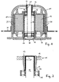
- the electric motor shown in Fig. 1 is an external rotor motor in flange construction. It has a bell-shaped, the stator 10 embracing rotor 11, wherein in the bottom 12 of the rotor 11, a pipe section 13 is fixed for receiving the rotor shaft 14.
- This rotor shaft 14 is rotatably supported by means of two bearings in an axle tube 17 of the stator 10.
- the axle tube 17 opens with its end remote from the pipe section 13 in a flange 18, which serves to fix the electric motor.
- the axle tube 17 carries the stator poles 19.
- the stator poles 19 opposite permanent magnets 25 are mounted on the outside of the rotor 11, a flange 20 is fixed to the rotor blades, not shown, of a fan or an impeller can be attached.
- a tube piece 13 may e.g. then omitted when the rotor 11 has a large wall thickness or thickening at the appropriate location. Instead of the pipe section then enters a concentric bore in the rotor eleventh
- the electric motor is not designed as an EC motor but as an asynchronous motor, then takes the place of the permanent magnets 25, a squirrel cage arrangement.
- a bushing or sleeve 21 of insulating plastic is disposed between the inner surface of the tubular member 13 and the corresponding outer surface of the rotor shaft 14.
- This sleeve 21 has at its bearing end a radial extension 22 to electrically isolate the pipe section 13 with respect to the bearing 15. Instead of the radial extension 22 could also occur a corresponding insulating disk.
- To increase the strength of the sleeve 21 may be fixed by means of a thin adhesive application in the pipe section 13 and on the rotor shaft 14. The attachment of this sleeve 21 is compared to conventional arrangements no additional operation, since so far for the exact fixation of the rotor shaft 14 relative to the rotor 11 metallic sleeves or bushings have been used.
- the electrical insulation of the rotor 11 by means of the sleeve 21 serves to prevent leakage currents between the rotor and stator, which occur in particular during operation by frequency converter or electronic EC control devices with an AC voltage higher pulse or switching frequency. These currents represent a risk to the life of the bearings between rotor and stator.
- Fig. 2 shows a variant of the insulation between the rotor shaft 14 and rotor 11 is shown in a detailed view.
- greatly shortened insulating sleeve or sleeve 23 is provided, which is arranged on the bearing-side end portion of the pipe section 13 and also has a radial extension 22 for isolation from the bearing 15. It serves only for pre-centering. Subsequently, the remaining space between pipe section 13 and rotor shaft 14 is poured with a plastic compound or an adhesive 24 or a resin. The sleeve 23 serves to seal against the adhesive 24.
- the front side of the rotor shaft 14 is additionally coated with adhesive 24, which is not absolutely necessary.
- a sleeve 21 or 23 can also be omitted entirely in an alternative embodiment.
- the exact centering must be ensured by other measures until the plastic material is cured.
- the electric motor shown in Fig. 3 as an embodiment of the invention is an external rotor motor shaft design.
- the rotor 26 has a rotor housing 27 which receives the inboard stator 28.
- the stator 28 is fixed to a stator shaft 29 which extends through the rotor housing 27. This is mounted at opposite locations on the stator 29 by two bearings 30, 31. These bearings sit in bearing plates or bearing recesses 32, 33 of the molded rotor housing 27th
- insulating bushes or sleeves 34, 35 between the peripheral surfaces of the bearings 30, 31 and the corresponding mating surfaces of the bearing recesses 32, 33 are used. They serve instead of the usual steel sleeves to ensure the exact bearing seats of the bearings 30, 31 and in addition to the electrical insulation.
- insulating perforated discs 36, 37 are inserted from plastic. They also serve to electrically isolate the bearings 30, 31 from the rotor housing 27.
- the sleeves 34, 35 and / or the perforated discs 36, 37 may be fixed by an adhesive layer to increase the strength, as was the case with the first embodiment.
- the electric motor according to FIG. 3 can also be designed as an internal rotor motor, ie the stator and rotor are reversed and, instead of the stator axis, a rotor shaft occurs.
- the bearings 15, 16 may be isolated according to the embodiment shown in Fig. 3.
- an insulating sleeve and / or a plastic material could be arranged between the stator axis 29 and the stator 28 on the basis of the first exemplary embodiment.
Landscapes
- Engineering & Computer Science (AREA)
- Power Engineering (AREA)
- Motor Or Generator Frames (AREA)
- Motor Or Generator Cooling System (AREA)
- Permanent Magnet Type Synchronous Machine (AREA)
- Valve Device For Special Equipments (AREA)
- Transition And Organic Metals Composition Catalysts For Addition Polymerization (AREA)
- Glass Compositions (AREA)
Claims (6)
- Moteur électrique avec un stator (10) et un rotor (11) qui est monté tournant dans ou sur le stator (10), au moyen d'un agencement de paliers (15,16), un manchon (21, 23), isolant électriquement l'arbre de rotor (14) par rapport au rotor (11), et/ou une couche de matière plastique (24) étant prévu, caractérisé en ce que l'arbre de rotor (14), monté dans le stator (10), est relié dans une zone d'extrémité, par le manchon isolant (21, 23) et la couche de matière plastique (23), au rotor (11) en forme de cloche, entourant le stator (10), en ce que le manchon (21 ; 23) est disposé au moins en partie entre l'arbre de rotor (14) et une pièce tubulaire (13) concentrique, solidaire du rotor (11), ou la paroi intérieure d'un perçage concentrique dans le rotor (11), et en ce que le manchon (23) ne s'étend qu'en partie entre l'arbre de rotor (14) et la pièce tubulaire (13) ou la paroi intérieure du perçage, le reste de l'interstice étant rempli par une matière plastique (24) isolante.
- Moteur électrique selon la revendication 1, caractérisé en ce qu'une zone (22) du manchon (21, 23) ou une rondelle isolante s'étend entre une face frontale de la pièce tubulaire (13) et un palier (15) de l'agencement de paliers (15, 16), en particulier dans la direction radiale.
- Moteur électrique avec un stator (28) et un rotor (26) qui est monté tournant dans ou sur le stator (28), au moyen d'un agencement de paliers (30, 31), au moins un manchon (34, 35), isolant électriquement l'agencement de paliers (30, 31) par rapport au stator ou au rotor (26), et/ou une couche de matière plastique étant prévu, caractérisé en ce que le rotor (26) est monté, au moyen de paliers de l'agencement de paliers (30, 31), disposés sur des faces opposées de son boîtier de rotor (27), sur l'axe de stator (29) s'étendant à travers celui-ci, les manchons isolants (34, 35), entourant les paliers, s'étendant chacun en partie seulement entre les paliers (30, 31) et un évidement ou logement de palier (32, 33) correspondant, le reste de l'interstice étant rempli par une matière plastique isolante.
- Moteur électrique selon la revendication 3, caractérisé en ce que les rondelles isolantes (36, 37) sont disposées entre des faces frontales des paliers (30, 31) et les évidements ou logements de palier (32, 33) qui sont réalisés en tant qu'éléments isolants séparés ou formés sur les manchons (33, 35).
- Moteur électrique selon l'une des revendications précédentes, caractérisé en ce que les manchons (21, 23 ; 34, 35) sont réalisés sous la forme de manchons en matière plastique.
- Moteur électrique selon l'une des revendications précédentes, caractérisé en ce que la matière plastique est une colle ou une résine.
Priority Applications (3)
| Application Number | Priority Date | Filing Date | Title |
|---|---|---|---|
| DE50302489T DE50302489D1 (de) | 2003-03-01 | 2003-03-01 | Elektromotor |
| AT03004595T ATE319214T1 (de) | 2003-03-01 | 2003-03-01 | Elektromotor |
| EP03004595A EP1455434B1 (fr) | 2003-03-01 | 2003-03-01 | Moteur électrique |
Applications Claiming Priority (1)
| Application Number | Priority Date | Filing Date | Title |
|---|---|---|---|
| EP03004595A EP1455434B1 (fr) | 2003-03-01 | 2003-03-01 | Moteur électrique |
Publications (2)
| Publication Number | Publication Date |
|---|---|
| EP1455434A1 EP1455434A1 (fr) | 2004-09-08 |
| EP1455434B1 true EP1455434B1 (fr) | 2006-03-01 |
Family
ID=32798750
Family Applications (1)
| Application Number | Title | Priority Date | Filing Date |
|---|---|---|---|
| EP03004595A Expired - Lifetime EP1455434B1 (fr) | 2003-03-01 | 2003-03-01 | Moteur électrique |
Country Status (3)
| Country | Link |
|---|---|
| EP (1) | EP1455434B1 (fr) |
| AT (1) | ATE319214T1 (fr) |
| DE (1) | DE50302489D1 (fr) |
Families Citing this family (11)
| Publication number | Priority date | Publication date | Assignee | Title |
|---|---|---|---|---|
| DE102018005364A1 (de) * | 2018-07-03 | 2020-01-09 | Ziehl-Abegg Se | Elektromotor, insbesondere EC-Motor |
| DE102020106461A1 (de) * | 2020-03-10 | 2021-09-16 | Schaeffler Technologies AG & Co. KG | Lageranordnung zur Integration in eine elektrische Antriebsanordnung für ein Fahrzeug und elektrische Antriebsanordnung mit der Lageranordnung |
| DE102020124652A1 (de) | 2020-09-22 | 2022-03-24 | Schaeffler Technologies AG & Co. KG | Radialflussmaschine |
| DE102021134418A1 (de) | 2021-12-22 | 2023-06-22 | Torqeedo Gmbh | Bootsantrieb |
| DE102023115914B4 (de) | 2023-06-19 | 2025-02-06 | Schaeffler Technologies AG & Co. KG | Wellenerdung, elektrische Maschine und Kit-of-parts |
| DE102023115921B4 (de) | 2023-06-19 | 2025-01-30 | Schaeffler Technologies AG & Co. KG | Wellenerdung, elektrische Maschine und Kit-of-parts |
| DE102023115922B4 (de) | 2023-06-19 | 2025-01-30 | Schaeffler Technologies AG & Co. KG | Wellenerdung, elektrische Maschine und Kit-of-Parts |
| DE102023115918B4 (de) | 2023-06-19 | 2025-02-06 | Schaeffler Technologies AG & Co. KG | Wellenerdung, elektrische Maschine sowie elektrisch betreibbarer Achsantriebsstrang |
| DE102023115919A1 (de) | 2023-06-19 | 2024-12-19 | Schaeffler Technologies AG & Co. KG | Wellenerdung, elektrische Maschine und Achsantriebsstrang |
| DE102023115917B4 (de) | 2023-06-19 | 2025-02-06 | Schaeffler Technologies AG & Co. KG | Wellenerdung, elektrische Maschine und elektrisch betreibbarer Achsantriebsstrang |
| DE102023115913A1 (de) | 2023-06-19 | 2024-12-19 | Schaeffler Technologies AG & Co. KG | Wellenerdung, elektrische Maschine und elektrisch betreibbarer Achsantriebsstrang |
Family Cites Families (7)
| Publication number | Priority date | Publication date | Assignee | Title |
|---|---|---|---|---|
| DE8029066U1 (de) * | 1981-02-26 | Siemens Ag, 1000 Berlin Und 8000 Muenchen | Isoliertes Wälzlager | |
| DE3422743A1 (de) * | 1984-06-19 | 1985-12-19 | Ebm Elektrobau Mulfingen Gmbh & Co, 7119 Mulfingen | Aussenlaeufermotor mit angeschraubtem motorflansch |
| DE4004812A1 (de) * | 1990-02-16 | 1991-09-05 | Licentia Gmbh | Verfahren zum herstellen elektrisch isolierter ankerwellen fuer elektrische maschinen |
| DE19631988A1 (de) * | 1996-08-08 | 1998-02-12 | Dieter Westerhoff | Kugel- bzw. wälzgelagerter Großelektromotor |
| JPH10295069A (ja) * | 1997-04-18 | 1998-11-04 | Hitachi Ltd | ファン用ブラシレスモートル |
| JP3635948B2 (ja) * | 1998-11-17 | 2005-04-06 | 三菱電機株式会社 | 回転電機 |
| JP3370944B2 (ja) * | 1999-02-24 | 2003-01-27 | デンヨー株式会社 | 回転電機の軸受け装置 |
-
2003
- 2003-03-01 AT AT03004595T patent/ATE319214T1/de not_active IP Right Cessation
- 2003-03-01 EP EP03004595A patent/EP1455434B1/fr not_active Expired - Lifetime
- 2003-03-01 DE DE50302489T patent/DE50302489D1/de not_active Expired - Lifetime
Also Published As
| Publication number | Publication date |
|---|---|
| EP1455434A1 (fr) | 2004-09-08 |
| DE50302489D1 (de) | 2006-04-27 |
| ATE319214T1 (de) | 2006-03-15 |
Similar Documents
| Publication | Publication Date | Title |
|---|---|---|
| EP1689065B1 (fr) | Stator pour machine électrique et sa méthode de fabrication | |
| EP0846364B1 (fr) | Moteur electrique | |
| DE102016202463A1 (de) | Elektronische Steuervorrichtung, Motorsteuervorrichtung und elektrische Fluidpumpe | |
| DE102016209627B4 (de) | Struktur für Schleifring und Bürste von Synchronmotor mit gewickeltem Rotor | |
| EP2923436B1 (fr) | Stator pourvu d'un enrobage et machine électrique équipée du stator | |
| DE102009002953B4 (de) | Schwungrad, Brennkraftmaschine mit Schwungrad sowie System aus einer Brennkraftmaschine und einer anzutreibenden Maschine, Verwendung des Systems | |
| EP1777416A1 (fr) | Pompe à moteur intégré | |
| EP1455434A1 (fr) | Moteur électrique | |
| DE202011101568U1 (de) | E-Motor mit Wuchtmaterial | |
| DE102007049209B4 (de) | Gleichstrommotor | |
| DE102021109498A1 (de) | AUßENLÄUFERMOTOR | |
| DE102015210788A1 (de) | Lagerschildsystem und elektromotorischer Antrieb mit einem Lagerschildsystem | |
| EP0713282B1 (fr) | Moteur à manchon d'entrefer | |
| DE102016211127A1 (de) | Elektrische Maschine für ein Haushaltsgerät mit zumindest teilweise umspritzten Stator, Pumpe, Haushaltsgerät sowie Verfahren | |
| EP1179141B1 (fr) | Dispositif, en particulier moteur a gaine, destine a la conversion d'energie electrique en energie mecanique et/ou inversement | |
| DE102010013675A1 (de) | Axialmagnetlager | |
| EP1209799B1 (fr) | Rotor d'une machine électrique et son procédé de fabrication | |
| EP1420502A2 (fr) | Moteur électrique | |
| DE102009042765B4 (de) | Permanenterregte Synchronmaschine | |
| DE202008015201U1 (de) | Koaxial angeordneter Elektromotor | |
| DE102009020092A1 (de) | Elektrische Maschine | |
| WO2004068676A1 (fr) | Machine electrique comportant un systeme de palier | |
| DE10060940A1 (de) | Motor und Verfahren zur Montage | |
| EP1568119B1 (fr) | Machine electrique comportant un dispositif bague collectrice | |
| WO2020239299A1 (fr) | Rotor destiné à une machine électrique tournante |
Legal Events
| Date | Code | Title | Description |
|---|---|---|---|
| PUAI | Public reference made under article 153(3) epc to a published international application that has entered the european phase |
Free format text: ORIGINAL CODE: 0009012 |
|
| 17P | Request for examination filed |
Effective date: 20040603 |
|
| AK | Designated contracting states |
Kind code of ref document: A1 Designated state(s): AT BE BG CH CY CZ DE DK EE ES FI FR GB GR HU IE IT LI LU MC NL PT RO SE SI SK TR |
|
| AX | Request for extension of the european patent |
Extension state: AL LT LV MK |
|
| 17Q | First examination report despatched |
Effective date: 20040908 |
|
| AKX | Designation fees paid |
Designated state(s): AT BE BG CH CY CZ DE DK EE ES FI FR GB GR HU IE IT LI LU MC NL PT RO SE SI SK TR |
|
| GRAP | Despatch of communication of intention to grant a patent |
Free format text: ORIGINAL CODE: EPIDOSNIGR1 |
|
| GRAS | Grant fee paid |
Free format text: ORIGINAL CODE: EPIDOSNIGR3 |
|
| GRAA | (expected) grant |
Free format text: ORIGINAL CODE: 0009210 |
|
| AK | Designated contracting states |
Kind code of ref document: B1 Designated state(s): AT BE BG CH CY CZ DE DK EE ES FI FR GB GR HU IE IT LI LU MC NL PT RO SE SI SK TR |
|
| PG25 | Lapsed in a contracting state [announced via postgrant information from national office to epo] |
Ref country code: IT Free format text: LAPSE BECAUSE OF FAILURE TO SUBMIT A TRANSLATION OF THE DESCRIPTION OR TO PAY THE FEE WITHIN THE PRESCRIBED TIME-LIMIT;WARNING: LAPSES OF ITALIAN PATENTS WITH EFFECTIVE DATE BEFORE 2007 MAY HAVE OCCURRED AT ANY TIME BEFORE 2007. THE CORRECT EFFECTIVE DATE MAY BE DIFFERENT FROM THE ONE RECORDED. Effective date: 20060301 Ref country code: NL Free format text: LAPSE BECAUSE OF FAILURE TO SUBMIT A TRANSLATION OF THE DESCRIPTION OR TO PAY THE FEE WITHIN THE PRESCRIBED TIME-LIMIT Effective date: 20060301 Ref country code: FI Free format text: LAPSE BECAUSE OF FAILURE TO SUBMIT A TRANSLATION OF THE DESCRIPTION OR TO PAY THE FEE WITHIN THE PRESCRIBED TIME-LIMIT Effective date: 20060301 Ref country code: GB Free format text: LAPSE BECAUSE OF FAILURE TO SUBMIT A TRANSLATION OF THE DESCRIPTION OR TO PAY THE FEE WITHIN THE PRESCRIBED TIME-LIMIT Effective date: 20060301 Ref country code: SK Free format text: LAPSE BECAUSE OF FAILURE TO SUBMIT A TRANSLATION OF THE DESCRIPTION OR TO PAY THE FEE WITHIN THE PRESCRIBED TIME-LIMIT Effective date: 20060301 Ref country code: IE Free format text: LAPSE BECAUSE OF FAILURE TO SUBMIT A TRANSLATION OF THE DESCRIPTION OR TO PAY THE FEE WITHIN THE PRESCRIBED TIME-LIMIT Effective date: 20060301 Ref country code: SI Free format text: LAPSE BECAUSE OF FAILURE TO SUBMIT A TRANSLATION OF THE DESCRIPTION OR TO PAY THE FEE WITHIN THE PRESCRIBED TIME-LIMIT Effective date: 20060301 Ref country code: AT Free format text: LAPSE BECAUSE OF NON-PAYMENT OF DUE FEES Effective date: 20060301 Ref country code: RO Free format text: LAPSE BECAUSE OF FAILURE TO SUBMIT A TRANSLATION OF THE DESCRIPTION OR TO PAY THE FEE WITHIN THE PRESCRIBED TIME-LIMIT Effective date: 20060301 |
|
| REG | Reference to a national code |
Ref country code: GB Ref legal event code: FG4D Free format text: NOT ENGLISH |
|
| REG | Reference to a national code |
Ref country code: CH Ref legal event code: EP |
|
| PG25 | Lapsed in a contracting state [announced via postgrant information from national office to epo] |
Ref country code: MC Free format text: LAPSE BECAUSE OF NON-PAYMENT OF DUE FEES Effective date: 20060331 Ref country code: BE Free format text: LAPSE BECAUSE OF NON-PAYMENT OF DUE FEES Effective date: 20060331 |
|
| REG | Reference to a national code |
Ref country code: IE Ref legal event code: FG4D Free format text: LANGUAGE OF EP DOCUMENT: GERMAN |
|
| REF | Corresponds to: |
Ref document number: 50302489 Country of ref document: DE Date of ref document: 20060427 Kind code of ref document: P |
|
| PG25 | Lapsed in a contracting state [announced via postgrant information from national office to epo] |
Ref country code: BG Free format text: LAPSE BECAUSE OF FAILURE TO SUBMIT A TRANSLATION OF THE DESCRIPTION OR TO PAY THE FEE WITHIN THE PRESCRIBED TIME-LIMIT Effective date: 20060601 Ref country code: DK Free format text: LAPSE BECAUSE OF FAILURE TO SUBMIT A TRANSLATION OF THE DESCRIPTION OR TO PAY THE FEE WITHIN THE PRESCRIBED TIME-LIMIT Effective date: 20060601 |
|
| PG25 | Lapsed in a contracting state [announced via postgrant information from national office to epo] |
Ref country code: ES Free format text: LAPSE BECAUSE OF FAILURE TO SUBMIT A TRANSLATION OF THE DESCRIPTION OR TO PAY THE FEE WITHIN THE PRESCRIBED TIME-LIMIT Effective date: 20060612 |
|
| REG | Reference to a national code |
Ref country code: SE Ref legal event code: TRGR |
|
| PG25 | Lapsed in a contracting state [announced via postgrant information from national office to epo] |
Ref country code: PT Free format text: LAPSE BECAUSE OF FAILURE TO SUBMIT A TRANSLATION OF THE DESCRIPTION OR TO PAY THE FEE WITHIN THE PRESCRIBED TIME-LIMIT Effective date: 20060801 |
|
| NLV1 | Nl: lapsed or annulled due to failure to fulfill the requirements of art. 29p and 29m of the patents act | ||
| GBV | Gb: ep patent (uk) treated as always having been void in accordance with gb section 77(7)/1977 [no translation filed] |
Effective date: 20060301 |
|
| REG | Reference to a national code |
Ref country code: IE Ref legal event code: FD4D |
|
| PLBE | No opposition filed within time limit |
Free format text: ORIGINAL CODE: 0009261 |
|
| STAA | Information on the status of an ep patent application or granted ep patent |
Free format text: STATUS: NO OPPOSITION FILED WITHIN TIME LIMIT |
|
| 26N | No opposition filed |
Effective date: 20061204 |
|
| EN | Fr: translation not filed | ||
| REG | Reference to a national code |
Ref country code: CH Ref legal event code: PL |
|
| BERE | Be: lapsed |
Owner name: GEBHARDT VENTILATOREN G.M.B.H. & CO. Effective date: 20060331 |
|
| PG25 | Lapsed in a contracting state [announced via postgrant information from national office to epo] |
Ref country code: CH Free format text: LAPSE BECAUSE OF NON-PAYMENT OF DUE FEES Effective date: 20070331 Ref country code: LI Free format text: LAPSE BECAUSE OF NON-PAYMENT OF DUE FEES Effective date: 20070331 |
|
| PG25 | Lapsed in a contracting state [announced via postgrant information from national office to epo] |
Ref country code: FR Free format text: LAPSE BECAUSE OF FAILURE TO SUBMIT A TRANSLATION OF THE DESCRIPTION OR TO PAY THE FEE WITHIN THE PRESCRIBED TIME-LIMIT Effective date: 20070309 Ref country code: GR Free format text: LAPSE BECAUSE OF FAILURE TO SUBMIT A TRANSLATION OF THE DESCRIPTION OR TO PAY THE FEE WITHIN THE PRESCRIBED TIME-LIMIT Effective date: 20060602 Ref country code: CZ Free format text: LAPSE BECAUSE OF FAILURE TO SUBMIT A TRANSLATION OF THE DESCRIPTION OR TO PAY THE FEE WITHIN THE PRESCRIBED TIME-LIMIT Effective date: 20060301 |
|
| PG25 | Lapsed in a contracting state [announced via postgrant information from national office to epo] |
Ref country code: EE Free format text: LAPSE BECAUSE OF FAILURE TO SUBMIT A TRANSLATION OF THE DESCRIPTION OR TO PAY THE FEE WITHIN THE PRESCRIBED TIME-LIMIT Effective date: 20060301 |
|
| PG25 | Lapsed in a contracting state [announced via postgrant information from national office to epo] |
Ref country code: HU Free format text: LAPSE BECAUSE OF FAILURE TO SUBMIT A TRANSLATION OF THE DESCRIPTION OR TO PAY THE FEE WITHIN THE PRESCRIBED TIME-LIMIT Effective date: 20060902 Ref country code: TR Free format text: LAPSE BECAUSE OF FAILURE TO SUBMIT A TRANSLATION OF THE DESCRIPTION OR TO PAY THE FEE WITHIN THE PRESCRIBED TIME-LIMIT Effective date: 20060301 Ref country code: LU Free format text: LAPSE BECAUSE OF NON-PAYMENT OF DUE FEES Effective date: 20060301 |
|
| PG25 | Lapsed in a contracting state [announced via postgrant information from national office to epo] |
Ref country code: FR Free format text: LAPSE BECAUSE OF FAILURE TO SUBMIT A TRANSLATION OF THE DESCRIPTION OR TO PAY THE FEE WITHIN THE PRESCRIBED TIME-LIMIT Effective date: 20060331 |
|
| PG25 | Lapsed in a contracting state [announced via postgrant information from national office to epo] |
Ref country code: FR Free format text: LAPSE BECAUSE OF FAILURE TO SUBMIT A TRANSLATION OF THE DESCRIPTION OR TO PAY THE FEE WITHIN THE PRESCRIBED TIME-LIMIT Effective date: 20060301 Ref country code: CY Free format text: LAPSE BECAUSE OF FAILURE TO SUBMIT A TRANSLATION OF THE DESCRIPTION OR TO PAY THE FEE WITHIN THE PRESCRIBED TIME-LIMIT Effective date: 20060301 |
|
| PGFP | Annual fee paid to national office [announced via postgrant information from national office to epo] |
Ref country code: DE Payment date: 20220329 Year of fee payment: 20 |
|
| PGFP | Annual fee paid to national office [announced via postgrant information from national office to epo] |
Ref country code: SE Payment date: 20220327 Year of fee payment: 20 |
|
| REG | Reference to a national code |
Ref country code: DE Ref legal event code: R071 Ref document number: 50302489 Country of ref document: DE |
|
| REG | Reference to a national code |
Ref country code: SE Ref legal event code: EUG |