EP1455351B1 - Optical information reproducing method and optical information processing apparatus - Google Patents
Optical information reproducing method and optical information processing apparatus Download PDFInfo
- Publication number
- EP1455351B1 EP1455351B1 EP02775308A EP02775308A EP1455351B1 EP 1455351 B1 EP1455351 B1 EP 1455351B1 EP 02775308 A EP02775308 A EP 02775308A EP 02775308 A EP02775308 A EP 02775308A EP 1455351 B1 EP1455351 B1 EP 1455351B1
- Authority
- EP
- European Patent Office
- Prior art keywords
- optical
- light
- polarized
- polarized component
- recording medium
- Prior art date
- Legal status (The legal status is an assumption and is not a legal conclusion. Google has not performed a legal analysis and makes no representation as to the accuracy of the status listed.)
- Expired - Fee Related
Links
Images


Classifications
-
- G—PHYSICS
- G11—INFORMATION STORAGE
- G11B—INFORMATION STORAGE BASED ON RELATIVE MOVEMENT BETWEEN RECORD CARRIER AND TRANSDUCER
- G11B7/00—Recording or reproducing by optical means, e.g. recording using a thermal beam of optical radiation by modifying optical properties or the physical structure, reproducing using an optical beam at lower power by sensing optical properties; Record carriers therefor
- G11B7/24—Record carriers characterised by shape, structure or physical properties, or by the selection of the material
- G11B7/241—Record carriers characterised by shape, structure or physical properties, or by the selection of the material characterised by the selection of the material
- G11B7/252—Record carriers characterised by shape, structure or physical properties, or by the selection of the material characterised by the selection of the material of layers other than recording layers
-
- B—PERFORMING OPERATIONS; TRANSPORTING
- B82—NANOTECHNOLOGY
- B82Y—SPECIFIC USES OR APPLICATIONS OF NANOSTRUCTURES; MEASUREMENT OR ANALYSIS OF NANOSTRUCTURES; MANUFACTURE OR TREATMENT OF NANOSTRUCTURES
- B82Y10/00—Nanotechnology for information processing, storage or transmission, e.g. quantum computing or single electron logic
-
- G—PHYSICS
- G11—INFORMATION STORAGE
- G11B—INFORMATION STORAGE BASED ON RELATIVE MOVEMENT BETWEEN RECORD CARRIER AND TRANSDUCER
- G11B7/00—Recording or reproducing by optical means, e.g. recording using a thermal beam of optical radiation by modifying optical properties or the physical structure, reproducing using an optical beam at lower power by sensing optical properties; Record carriers therefor
- G11B7/004—Recording, reproducing or erasing methods; Read, write or erase circuits therefor
- G11B7/005—Reproducing
-
- G—PHYSICS
- G11—INFORMATION STORAGE
- G11B—INFORMATION STORAGE BASED ON RELATIVE MOVEMENT BETWEEN RECORD CARRIER AND TRANSDUCER
- G11B7/00—Recording or reproducing by optical means, e.g. recording using a thermal beam of optical radiation by modifying optical properties or the physical structure, reproducing using an optical beam at lower power by sensing optical properties; Record carriers therefor
- G11B7/12—Heads, e.g. forming of the optical beam spot or modulation of the optical beam
- G11B7/135—Means for guiding the beam from the source to the record carrier or from the record carrier to the detector
- G11B7/1356—Double or multiple prisms, i.e. having two or more prisms in cooperation
-
- G—PHYSICS
- G11—INFORMATION STORAGE
- G11B—INFORMATION STORAGE BASED ON RELATIVE MOVEMENT BETWEEN RECORD CARRIER AND TRANSDUCER
- G11B7/00—Recording or reproducing by optical means, e.g. recording using a thermal beam of optical radiation by modifying optical properties or the physical structure, reproducing using an optical beam at lower power by sensing optical properties; Record carriers therefor
- G11B7/24—Record carriers characterised by shape, structure or physical properties, or by the selection of the material
- G11B7/241—Record carriers characterised by shape, structure or physical properties, or by the selection of the material characterised by the selection of the material
- G11B7/242—Record carriers characterised by shape, structure or physical properties, or by the selection of the material characterised by the selection of the material of recording layers
- G11B7/243—Record carriers characterised by shape, structure or physical properties, or by the selection of the material characterised by the selection of the material of recording layers comprising inorganic materials only, e.g. ablative layers
- G11B2007/24302—Metals or metalloids
- G11B2007/24312—Metals or metalloids group 14 elements (e.g. Si, Ge, Sn)
-
- G—PHYSICS
- G11—INFORMATION STORAGE
- G11B—INFORMATION STORAGE BASED ON RELATIVE MOVEMENT BETWEEN RECORD CARRIER AND TRANSDUCER
- G11B7/00—Recording or reproducing by optical means, e.g. recording using a thermal beam of optical radiation by modifying optical properties or the physical structure, reproducing using an optical beam at lower power by sensing optical properties; Record carriers therefor
- G11B7/24—Record carriers characterised by shape, structure or physical properties, or by the selection of the material
- G11B7/241—Record carriers characterised by shape, structure or physical properties, or by the selection of the material characterised by the selection of the material
- G11B7/242—Record carriers characterised by shape, structure or physical properties, or by the selection of the material characterised by the selection of the material of recording layers
- G11B7/243—Record carriers characterised by shape, structure or physical properties, or by the selection of the material characterised by the selection of the material of recording layers comprising inorganic materials only, e.g. ablative layers
- G11B2007/24302—Metals or metalloids
- G11B2007/24314—Metals or metalloids group 15 elements (e.g. Sb, Bi)
-
- G—PHYSICS
- G11—INFORMATION STORAGE
- G11B—INFORMATION STORAGE BASED ON RELATIVE MOVEMENT BETWEEN RECORD CARRIER AND TRANSDUCER
- G11B7/00—Recording or reproducing by optical means, e.g. recording using a thermal beam of optical radiation by modifying optical properties or the physical structure, reproducing using an optical beam at lower power by sensing optical properties; Record carriers therefor
- G11B7/24—Record carriers characterised by shape, structure or physical properties, or by the selection of the material
- G11B7/241—Record carriers characterised by shape, structure or physical properties, or by the selection of the material characterised by the selection of the material
- G11B7/242—Record carriers characterised by shape, structure or physical properties, or by the selection of the material characterised by the selection of the material of recording layers
- G11B7/243—Record carriers characterised by shape, structure or physical properties, or by the selection of the material characterised by the selection of the material of recording layers comprising inorganic materials only, e.g. ablative layers
- G11B2007/24302—Metals or metalloids
- G11B2007/24316—Metals or metalloids group 16 elements (i.e. chalcogenides, Se, Te)
-
- G—PHYSICS
- G11—INFORMATION STORAGE
- G11B—INFORMATION STORAGE BASED ON RELATIVE MOVEMENT BETWEEN RECORD CARRIER AND TRANSDUCER
- G11B7/00—Recording or reproducing by optical means, e.g. recording using a thermal beam of optical radiation by modifying optical properties or the physical structure, reproducing using an optical beam at lower power by sensing optical properties; Record carriers therefor
- G11B7/24—Record carriers characterised by shape, structure or physical properties, or by the selection of the material
- G11B7/241—Record carriers characterised by shape, structure or physical properties, or by the selection of the material characterised by the selection of the material
- G11B7/252—Record carriers characterised by shape, structure or physical properties, or by the selection of the material characterised by the selection of the material of layers other than recording layers
- G11B7/257—Record carriers characterised by shape, structure or physical properties, or by the selection of the material characterised by the selection of the material of layers other than recording layers of layers having properties involved in recording or reproduction, e.g. optical interference layers or sensitising layers or dielectric layers, which are protecting the recording layers
- G11B2007/25705—Record carriers characterised by shape, structure or physical properties, or by the selection of the material characterised by the selection of the material of layers other than recording layers of layers having properties involved in recording or reproduction, e.g. optical interference layers or sensitising layers or dielectric layers, which are protecting the recording layers consisting essentially of inorganic materials
- G11B2007/25706—Record carriers characterised by shape, structure or physical properties, or by the selection of the material characterised by the selection of the material of layers other than recording layers of layers having properties involved in recording or reproduction, e.g. optical interference layers or sensitising layers or dielectric layers, which are protecting the recording layers consisting essentially of inorganic materials containing transition metal elements (Zn, Fe, Co, Ni, Pt)
-
- G—PHYSICS
- G11—INFORMATION STORAGE
- G11B—INFORMATION STORAGE BASED ON RELATIVE MOVEMENT BETWEEN RECORD CARRIER AND TRANSDUCER
- G11B7/00—Recording or reproducing by optical means, e.g. recording using a thermal beam of optical radiation by modifying optical properties or the physical structure, reproducing using an optical beam at lower power by sensing optical properties; Record carriers therefor
- G11B7/24—Record carriers characterised by shape, structure or physical properties, or by the selection of the material
- G11B7/241—Record carriers characterised by shape, structure or physical properties, or by the selection of the material characterised by the selection of the material
- G11B7/252—Record carriers characterised by shape, structure or physical properties, or by the selection of the material characterised by the selection of the material of layers other than recording layers
- G11B7/257—Record carriers characterised by shape, structure or physical properties, or by the selection of the material characterised by the selection of the material of layers other than recording layers of layers having properties involved in recording or reproduction, e.g. optical interference layers or sensitising layers or dielectric layers, which are protecting the recording layers
- G11B2007/25705—Record carriers characterised by shape, structure or physical properties, or by the selection of the material characterised by the selection of the material of layers other than recording layers of layers having properties involved in recording or reproduction, e.g. optical interference layers or sensitising layers or dielectric layers, which are protecting the recording layers consisting essentially of inorganic materials
- G11B2007/2571—Record carriers characterised by shape, structure or physical properties, or by the selection of the material characterised by the selection of the material of layers other than recording layers of layers having properties involved in recording or reproduction, e.g. optical interference layers or sensitising layers or dielectric layers, which are protecting the recording layers consisting essentially of inorganic materials containing group 14 elements except carbon (Si, Ge, Sn, Pb)
-
- G—PHYSICS
- G11—INFORMATION STORAGE
- G11B—INFORMATION STORAGE BASED ON RELATIVE MOVEMENT BETWEEN RECORD CARRIER AND TRANSDUCER
- G11B7/00—Recording or reproducing by optical means, e.g. recording using a thermal beam of optical radiation by modifying optical properties or the physical structure, reproducing using an optical beam at lower power by sensing optical properties; Record carriers therefor
- G11B7/24—Record carriers characterised by shape, structure or physical properties, or by the selection of the material
- G11B7/241—Record carriers characterised by shape, structure or physical properties, or by the selection of the material characterised by the selection of the material
- G11B7/252—Record carriers characterised by shape, structure or physical properties, or by the selection of the material characterised by the selection of the material of layers other than recording layers
- G11B7/257—Record carriers characterised by shape, structure or physical properties, or by the selection of the material characterised by the selection of the material of layers other than recording layers of layers having properties involved in recording or reproduction, e.g. optical interference layers or sensitising layers or dielectric layers, which are protecting the recording layers
- G11B2007/25705—Record carriers characterised by shape, structure or physical properties, or by the selection of the material characterised by the selection of the material of layers other than recording layers of layers having properties involved in recording or reproduction, e.g. optical interference layers or sensitising layers or dielectric layers, which are protecting the recording layers consisting essentially of inorganic materials
- G11B2007/25715—Record carriers characterised by shape, structure or physical properties, or by the selection of the material characterised by the selection of the material of layers other than recording layers of layers having properties involved in recording or reproduction, e.g. optical interference layers or sensitising layers or dielectric layers, which are protecting the recording layers consisting essentially of inorganic materials containing oxygen
-
- G—PHYSICS
- G11—INFORMATION STORAGE
- G11B—INFORMATION STORAGE BASED ON RELATIVE MOVEMENT BETWEEN RECORD CARRIER AND TRANSDUCER
- G11B7/00—Recording or reproducing by optical means, e.g. recording using a thermal beam of optical radiation by modifying optical properties or the physical structure, reproducing using an optical beam at lower power by sensing optical properties; Record carriers therefor
- G11B7/24—Record carriers characterised by shape, structure or physical properties, or by the selection of the material
- G11B7/241—Record carriers characterised by shape, structure or physical properties, or by the selection of the material characterised by the selection of the material
- G11B7/252—Record carriers characterised by shape, structure or physical properties, or by the selection of the material characterised by the selection of the material of layers other than recording layers
- G11B7/257—Record carriers characterised by shape, structure or physical properties, or by the selection of the material characterised by the selection of the material of layers other than recording layers of layers having properties involved in recording or reproduction, e.g. optical interference layers or sensitising layers or dielectric layers, which are protecting the recording layers
- G11B2007/25705—Record carriers characterised by shape, structure or physical properties, or by the selection of the material characterised by the selection of the material of layers other than recording layers of layers having properties involved in recording or reproduction, e.g. optical interference layers or sensitising layers or dielectric layers, which are protecting the recording layers consisting essentially of inorganic materials
- G11B2007/25716—Record carriers characterised by shape, structure or physical properties, or by the selection of the material characterised by the selection of the material of layers other than recording layers of layers having properties involved in recording or reproduction, e.g. optical interference layers or sensitising layers or dielectric layers, which are protecting the recording layers consisting essentially of inorganic materials containing sulfur
Definitions
- the present invention relates to an optical information reproducing method, an optical head device, and an optical information processing apparatus for optically reproducing information from optical disks or optical cards.
- JP 2000-348377 discloses a technique that uses near-field light to perform recording/reproduction beyond the diffraction limit of light.
- FIG. 8 shows the cross-sectional configuration of an optical recording medium used in super-resolution recording/reproduction.
- This optical recording medium 1 includes a transparent substrate 11 and a first protective layer 12, a mask layer 13, a second protective layer 14, a recording layer 15, and a third protective layer 16 that are formed on the transparent substrate 11 in the indicated order.
- the first to third protective layers 12, 14, and 16 are made of ZnS-SiO 2 .
- the recording layer 15 is made of a phase change material (e.g., a multinary compound such as GeSbTe).
- the mask layer 13 is made of silver oxide that is decomposed into oxygen and silver by heat.
- the optical recording medium 1 When the optical recording medium 1 is irradiated with convergent light L1, a focusing spot is formed in the mask layer 13, and then the silver oxide is decomposed into oxygen and silver to change the refractive index in a high-temperature portion of the focusing spot where the temperature exceeds a given threshold value.
- an aperture 17 smaller than the focusing spot diameter is formed in the mask layer 13 as a refractive index changing region. It is possible to write a recording mark 18 into the recording layer 15 or read the recording mark 18 from the recording layer 15 using near-field light generated at the aperture 17.
- the recording layer 15 is located at the position where the near-field light generated in the mask layer 13 can reach, thereby achieving both high-speed writing and high-speed reading.
- FIG. 9 shows a general optical head device 101 when used for reproducing information from the optical recording medium 1.
- the lateral direction of the sheet of this drawing is identified as an X-direction
- the vertical direction from the sheet surface is identified as a Y-direction
- the longitudinal direction of the sheet is identified as a Z-direction.
- a semiconductor laser 102 (a radiation light source) radiates linearly polarized light that is polarized in the X-direction.
- the light emitted from the semiconductor laser 102 enters a polarization beam splitter 103.
- the polarization beam splitter 103 has the functions of transmitting all the light polarized in the X-direction and reflecting all the light polarized in the Y-direction.
- the light passing through the polarization beam splitter 103 is converted into parallel light by a collimator lens 104, then converted into circularly polarized light by a quarter-wave plate 105, and focused to the inside of the optical recording medium 1 by an objective lens 106.
- the light reflected from the optical recording medium 1 again passes through the objective lens 106 and the quarter-wave plate 105, and thus is converted into linearly polarized light that is polarized in the Y-direction.
- This linearly polarized light further passes through the collimator lens 104 and enters the polarization beam splitter 103.
- the light entering the polarization beam splitter 103 is polarized in the Y-direction, and therefore is reflected by the polarization beam splitter 103.
- the reflected light passes through a cylindrical lens 107 or the like so that the wavefront is controlled to detect a servo signal.
- a photodetector 108 detects a reproduction signal and a servo signal.
- the quarter-wave plate 105 and the polarization beam splitter 103 are used to improve the light utilization efficiency. Even if the quarter-wave plate 105 is not provided, and the polarization beam splitter 103 is replaced with a non-polarization beam splitter, information can be recorded/reproduced.
- a general laser beam includes a noise component.
- the noise component is not a problem because the degree of signal modulation is sufficient.
- a recording mark smaller than the spot diameter of the laser beam should be read, so that the degree of modulation of a reproduction signal is reduced significantly. Therefore, the effect of the noise component of the laser beam cannot be ignored, which may lead to S/N degradation.
- EP 0555049 A2 discloses an optical head device comprising a radiation light source, a focusing optical system and a photodetector.
- JP 2000 348377 discloses an optical recording medium comprising a recording layer and a mask layer.
- An optical information reproducing method of the present invention is used for an optical recording medium.
- the optical recording medium includes a recording layer containing information and a mask layer that is located close to the recording layer and includes a nonlinear optical material whose optical properties are changed in accordance with incident light intensity.
- the method includes the following: irradiating the optical recording medium with convergent light that is polarized in a first direction to form an optical property changing region in a portion of a region of the mask layer that is exposed to the convergent light and then to irradiate the recording layer with the light that has passed through the optical property changing region, wherein a diameter of the optical property changing region is smaller than that of a focusing spot of the convergent light and a transmittance of the optical property changing region is changed by the irradiation of the convergent light; and detecting a reproduction signal by using a second polarized component; characterised in that the method further comprises dividing reflected light from the optical recording medium into a first polarized component that is polarized in the first direction and a second polarized component that is polarized in a second direction perpendicular to the first direction.
- An optical information processing apparatus of the present invention includes an optical recording medium and an optical head device.
- the optical recording medium includes a recording layer containing information and a mask layer that is located close to the recording layer and includes a nonlinear optical material whose optical properties are changed in accordance with incident light intensity.
- the optical head device includes the following: a radiation light source for radiating linearly polarized light that is polarized in a first direction; a focusing optical system for converging the light emitted from the radiation light source on the optical recording medium to form a tiny spot; a polarization separation optical system for dividing reflected light from the optical recording medium into a first polarized component that is polarized in the first direction and a second polarized component that is polarized in a second direction perpendicular to the first direction; and a photodetector for detecting a reproduction signal by receiving the second polarized component separated by the polarization separation optical system.
- An optical information reproducing method of the present invention is used for an optical recording medium.
- the optical recording medium includes a recording layer containing information and a mask layer that is located close to the recording layer and includes a nonlinear optical material whose optical properties are changed in accordance with incident light intensity.
- the method includes the following: irradiating the optical recording medium with convergent light that is polarized in a first direction; forming an optical property changing region in a portion of a region of the mask layer that is exposed to the convergent light; irradiating the recording layer with light passing through the optical property changing region; dividing reflected light from the optical recording medium into a first polarized component that is polarized in the first direction and a second polarized component that is polarized in a second direction perpendicular to the first direction; and detecting a reproduction signal by using the second polarized component.
- the reflected light from the optical recording medium used in the optical information reproducing method of the present invention includes light reflected from the recording layer and light reflected from the mask layer.
- the light reflected from the recording layer represents information (including reproduction information) recorded on the recording layer and has a high degree of modulation.
- the light reflected from the mask layer includes no reproduction information. There is a difference in polarization state between them. Specifically, the light reflected from the mask layer has the same polarization state as the convergent light for irradiation. In contrast, the light reflected from the recording layer is scattered in the optical property changing region of the mask layer, and also includes a polarized component perpendicular to the polarization direction of the convergent light.
- the optical information reproducing method of the present invention allows the component (the second polarized component), which is polarized in the direction (the second direction) perpendicular to the polarization direction (the first direction) of the irradiation light and is included in light that represents reproduction information and has a high degree of modulation, to be taken out of the reflected light from the optical recording medium and used to detect a reproduction signal.
- the component the second polarized component
- the second direction perpendicular to the polarization direction (the first direction) of the irradiation light and is included in light that represents reproduction information and has a high degree of modulation
- the nonlinear optical material of the mask layer may be at least one selected from antimony (Sb), silver oxide, a semiconductor, chalcogenide glass, and a thermochromic material.
- the semiconductor e.g., a semiconductor including elements such as silicon (Si) and germanium (Ge) can be used.
- the thermochromic material is a material that reversibly changes in color with temperature.
- a servo signal is detected by using the first polarized component that is separated from the reflected light from the optical recording medium.
- An optical head device of the present invention is used for reproducing information from an optical recording medium.
- the optical recording medium includes a recording layer containing the information and a mask layer that is located close to the recording layer and includes a nonlinear optical material whose optical properties are changed in accordance with incident light intensity.
- the optical head device includes the following: a radiation light source for radiating light that is polarized in a first direction; a focusing optical system for converging the light emitted from the radiation light source on the optical recording medium to form a tiny spot; a polarization separation optical system for dividing reflected light from the optical recording medium into a first polarized component that is polarized in the first direction and a second polarized component that is polarized in a second direction perpendicular to the first direction; and a photodetector for detecting a reproduction signal by receiving the second polarized component separated by the polarization separation optical system.
- the reflected light from the optical recording medium includes light that represents information recorded on the recording layer and has a high degree of modulation (the light reflected from the recording layer) and light that includes no reproduction information (the light reflected from the mask layer), as described above.
- the optical head device of the present invention can separate only the light with a high degree of modulation from the reflected light of the optical recording medium and detect a reproduction signal.
- S/N can be improved in super-resolution reproduction.
- the polarization separation optical system of the optical head device of the present invention may include, e.g., a polarization beam splitter that transmits all the first polarized component and reflects all the second polarized component or a polarization beam splitter that reflects all the first polarized component and transmits all the second polarized component.
- the polarization separation optical system may include either a diffraction element that diffracts all the first polarized component and transmits all the second polarized component or a polarizing prism that separates the first polarized component from the second polarized component.
- the optical head device of the present invention further includes a servo signal photodetector that detects a servo signal by receiving the first polarized component separated by the polarization separation optical system.
- An optical information processing apparatus of the present invention includes an optical recording medium and an optical head device.
- the optical recording medium includes a recording layer containing information and a mask layer that is located close to the recording layer and includes a nonlinear optical material whose optical properties are changed in accordance with incident light intensity.
- the optical head device includes the following: a radiation light source for radiating linearly polarized light that is polarized in a first direction; a focusing optical system for converging the light emitted from the radiation light source on the optical recording medium to form a tiny spot; a polarization separation optical system for dividing reflected light from the optical recording medium into a first polarized component that is polarized in the first direction and a second polarized component that is polarized in a second direction perpendicular to the first direction; and a photodetector for detecting a reproduction signal by receiving the second polarized component separated by the polarization separation optical system.
- the reflected light from the optical recording medium in the optical information processing apparatus of the present invention includes light that represents information recorded on the recording layer and has a high degree of modulation (the light reflected from the recording layer) and light that includes no reproduction information (the light reflected from the mask layer).
- the optical information processing apparatus of the present invention can separate only the light with a high degree of modulation from the reflected light of the optical recording medium and detect a reproduction signal.
- S/N can be improved in super-resolution reproduction.
- the nonlinear optical material of the mask layer of the optical recording medium may be at least one selected from Sb, silver oxide, a semiconductor, chalcogenide glass, and a thermochromic material.
- the semiconductor e.g., a semiconductor including elements such as Si and Ge can be used.
- the thermochromic material is a material that reversibly changes in color with temperature.
- the polarization separation optical system of the optical head device may include, e.g., a polarization beam splitter that transmits all the first polarized component and reflects all the second polarized component or a polarization beam splitter that reflects all the first polarized component and transmits all the second polarized component.
- the polarization separation optical system may include either a diffraction element that diffracts all the first polarized component and transmits all the second polarized component or a polarizing prism that separates the first polarized component from the second polarized component.
- the optical head device further includes a servo signal photodetector that detects a servo signal by receiving the first polarized component separated by the polarization separation optical system.
- An optical recording medium 1 of this embodiment includes a transparent substrate 11, a first protective layer 12, a mask layer 13, a second protective layer 14, a recording layer 15, and a third protective layer 16 in the indicated order from the incident side of a laser beam for recording/reproducing information.
- the transparent substrate 11 is made of a material that is transparent or almost transparent to the laser beam, and transmits or substantially transmits the laser beam.
- Guide grooves for the laser beam preferably are formed in the surface of the transparent substrate 11.
- FIG. 1 shows the shape of the optical recording medium 1 provided with the guide grooves.
- the mask layer 13 includes a nonlinear optical material whose optical properties are changed in accordance with incident light intensity.
- This embodiment uses a Sb film having a thickness of 20 nm.
- the recording layer 15 is provided to record information and made of a material whose state is changed by light or heat generation resulting from the absorption of light.
- This embodiment uses a Ge 30 Sb 15 Te 55 film having a thickness of 15 nm.
- the first to third protective layers 12, 14, and 16 are provided mainly to protect the mask layer 13 and the recording layer 15 and to adjust the optical properties so that the recording layer 13 can absorb light effectively.
- a material obtained by mixing ZnS with 20 mol% of SiO 2 is used, and the thicknesses of the first, second, and third protective layers 12, 14, and 16 are 40 nm, 20 nm, and 130 nm, respectively.
- the optical recording medium 1 is irradiated with a linearly polarized laser beam L1 that is convergent light focused by an objective lens (not shown).
- This irradiation light is diffracted by the aperture of the objective lens and has an intensity distribution with a shape close to Gaussian distribution in which the radius of a portion where the intensity is 1/e 2 with respect to the central portion is 0.41 ⁇ /NA ( ⁇ is the wavelength of a laser beam for irradiation, and NA is the numerical aperture of an objective lens).
- the optical property changing region has a high transmittance with respect to the laser beam L1 and serves as an aperture 17. The size of the aperture 17 is smaller than the spot of the laser beam L1 falling on the mask layer 13.
- the recordable/reproducible minimum mark size is determined by the size of the aperture 17 and independent of the diffraction limit. Accordingly, information of not more than the diffraction limit can be recorded/reproduced, i.e., so-called super-resolution recording/reproduction can be performed.
- the information recorded on the recording layer 15 is reproduced by detecting reflected light L3 of the laser beam L1.
- the reflected light L3 includes a component of light in the central portion of the spot (i.e., a central light component) L3a (not shown) and a component of light on the periphery of the spot (i.e., a peripheral light component) L3b (not shown).
- the central light component L3a is light that represents the information recorded on the recording layer 15 and has a high degree of modulation.
- the peripheral light component L3b is light that is reflected from the mask layer 13 before reaching the recording layer 15 and includes no reproduction information. For this reason, when a reproduction signal is detected from the whole of the reflected light L3, the degree of signal modulation is reduced, and S/N is degraded.
- the optical information reproducing method of the present invention allows the central light component L3a to be taken out of the reflected light L3 and detected as a reproduction signal, thus performing favorable reproduction with an improved degree of signal modulation.
- a difference in polarization between the central light component L3a and the peripheral light component L3b is utilized to remove the peripheral light component L3b from the reflected light L3. Since the peripheral light component L3b is reflected from the mask layer 13, the polarization direction is the same as that of the laser beam L1.
- the central light component L3a is scattered while passing through the aperture 17, and also includes a polarized component perpendicular to the laser beam L1. Therefore, when the polarized component perpendicular to the laser beam L1 is taken out of the reflected light L3 and detected, a reproduction signal having a high degree of modulation can be obtained. This makes it possible to reduce the effect of noise and improve S/N.
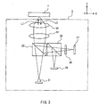
- FIG. 3 shows an optical head device 2 of this embodiment when used for reproducing information from the optical recording medium 1.
- the lateral direction of the sheet of this drawing is identified as an X-direction
- the vertical direction from the sheet surface is identified as a Y-direction
- the longitudinal direction of the sheet is identified as a Z-direction.
- a semiconductor laser 21 (a radiation light source) radiates linearly polarized light that is polarized in the X-direction (a first direction).
- a laser beam L1 emitted from the semiconductor laser 21 enters a polarization beam splitter 22.
- the polarization beam splitter 22 has the functions of dividing the light polarized in the X-direction into transmission and reflection at a desired ratio (e.g., a transmittance of 80% and a reflectance of 20% in this embodiment) and reflecting all the light polarized in the Y-direction (a second direction).
- the laser beam L1 passing through the polarization beam splitter 22 is converted into parallel light by a collimator lens 23 and focused to the inside of the optical recording medium 1 by an objective lens 24.
- the optical recording medium 1 has the structure as shown in FIGS. 1 and 2 .
- Reflected light L3 that is reflected from the optical recording medium 1 again passes through the objective lens 24 and the collimator lens 23, and then enters the polarization beam splitter 22, where 20% of the light polarized in the X-direction is reflected and all the light polarized in the Y-direction is reflected.
- the light reflected from the polarization beam splitter 22 further enters a polarization beam splitter 25 that serves as a polarization separation optical system.
- the polarization beam splitter 25 has the functions of transmitting all the light polarized in the X-direction and reflecting all the light polarized in the Y-direction. Therefore, the polarization beam splitter 25 can separate the component (a first polarized component) that is polarized in the X-direction from the component (a second polarized component) that is polarized in the Y-direction.
- a photodetector 28 receives the component polarized in the Y-direction and detects a reproduction signal.
- the light polarized in the X-direction that has passed through the polarization beam splitter 25 enters a hologram element 26, where the wavefront is transformed so as to detect a servo signal. Then, the light enters a photodetector 27 that serves as a servo signal photodetector.
- the photodetector 27 includes a plurality of light-receiving regions and can detect servo signals from the signals in each of the light-receiving regions.
- the optical head device 2 of this embodiment can separate the component that represents recorded information from the reflected light and perform super-resolution reproduction with improved S/N.
- the polarization beam splitter that transmits all the light polarized in the X-direction and reflects all the light polarized in the Y-direction is used as a polarization separation optical system.
- a polarization beam splitter that reflects all the light polarized in the X-direction and transmits all the light polarized in the Y-direction.
- FIG. 4 shows an optical head device 3 of this embodiment when used for reproducing information from the optical recording medium 1.
- the lateral direction of the sheet of this drawing is identified as an X-direction
- the vertical direction from the sheet surface is identified as a Y-direction
- the longitudinal direction of the sheet is identified as a Z-direction.
- a semiconductor laser 31 (a radiation light source) radiates linearly polarized light that is polarized in the X-direction (a first direction).
- a laser beam L1 emitted from the semiconductor laser 31 enters a polarization beam splitter 32.
- the polarization beam splitter 32 has the functions of transmitting all the light polarized in the X-direction and reflecting all the light polarized in the Y-direction (a second direction).
- the laser beam L1 passing through the polarization beam splitter 32 is converted into parallel light by a collimator lens 33 and focused to the inside of the optical recording medium 1 by an objective lens 34.
- the optical recording medium 1 has the structure as shown in FIGS. 1 and 2 .
- Reflected light L3 that is reflected from the optical recording medium 1 again passes through the objective lens 34 and the collimator lens 33, and then enters the polarization beam splitter 32, where all the light polarized in the X-direction (a first polarized component) is transmitted and all the light polarized in the Y-direction (a second polarized component) is reflected.
- the polarization beam splitter 32 functions as a polarization separation optical system that separates the first polarized component and the second polarized component from the reflected light.
- a photodetector 35 receives the component polarized in the Y-direction and detects a reproduction signal.
- the light polarized in the X-direction that has been separated by the polarization beam splitter 32 enters a hologram element 36, where the wavefront is transformed by diffraction of the hologram element 36 so as to detect a servo signal.
- the light enters a photodetector 37 that serves as a servo signal photodetector.
- the photodetector 37 includes a plurality of light-receiving regions and can detect servo signals from the signals in each of the light-receiving regions.
- the semiconductor laser 31 can be located close to the photodetector 37 for detecting a servo signal, thus improving stability. Moreover, the semiconductor laser 31, the photodetector 37, and the hologram element 36 are integrated in the same package, so that the optical head device can have higher stability.
- the optical head device 3 of this embodiment can separate the component that represents recorded information from the reflected light and perform super-resolution reproduction with improved S/N.
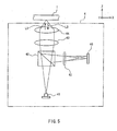
- FIG. 5 shows an optical head device 4 of this embodiment when used for reproducing information from the optical recording medium 1.
- the lateral direction of the sheet of this drawing is identified as an X-direction
- the vertical direction from the sheet surface is identified as a Y-direction
- the longitudinal direction of the sheet is identified as a Z-direction.
- a semiconductor laser 41 (a radiation light source) radiates linearly polarized light that is polarized in the X-direction (a first direction).
- a laser beam L1 emitted from the semiconductor laser 41 enters a polarization beam splitter 42.
- the polarization beam splitter 42 has the functions of dividing the light polarized in the X-direction into transmission and reflection at a desired ratio (e.g., a transmittance of 80% and a reflectance of 20% in this embodiment) and reflecting all the light polarized in the Y-direction (a second direction).
- the laser beam L1 passing through the polarization beam splitter 42 is converted into parallel light by a collimator lens 43 and focused to the inside of the optical recording medium 1 by an objective lens 44.
- the optical recording medium 1 has the structure as shown in FIGS. 1 and 2 .
- Reflected light L3 that is reflected from the optical recording medium 1 again passes through the objective lens 44 and the collimator lens 43, and then enters the polarization beam splitter 42, where 20% of the light polarized in the X-direction is reflected and all the light polarized in the Y-direction is reflected.
- the light reflected from the polarization beam splitter 42 further enters a polarization anisotropic hologram 45 that serves as a polarization separation optical system.
- the polarization anisotropic hologram 45 is a diffraction element that diffracts the component polarized in the X-direction (a first polarized component) at a desired wavefront so as to detect a servo signal and transmits the component polarized in the Y-direction (a second polarized component). Therefore, the polarization anisotropic hologram 45 can separate the two polarized components.
- the component polarized in the Y-direction that has been transmitted through the polarization anisotropic hologram 45 is detected in a light-receiving region of a photodetector 46 and converted into a reproduction signal.
- the component polarized in the X-direction that has been diffracted by the polarization anisotropic hologram 45 is detected in a plurality of light-receiving regions of the photodetector 46 and converted into servo signals.
- the photodetector 46 is used for a reproduction signal as well as a servo signal.
- the optical head device 4 of this embodiment can separate the component that represents recorded information from the reflected light and perform super-resolution reproduction with improved S/N.
- FIG. 6 shows an optical head device 5 of this embodiment when used for reproducing information from the optical recording medium 1.
- the lateral direction of the sheet of this drawing is identified as an X-direction
- the vertical direction from the sheet surface is identified as a Y-direction
- the longitudinal direction of the sheet is identified as a Z-direction.
- a semiconductor laser 51 (a radiation light source) radiates linearly polarized light that is polarized in the X-direction (a first direction).
- a laser beam L1 emitted from the semiconductor laser 51 enters a polarization beam splitter 52.
- the polarization beam splitter 52 has the functions of dividing the light polarized in the X-direction into transmission and reflection at a desired ratio (e.g., a transmittance of 80% and a reflectance of 20% in this embodiment) and reflecting all the light polarized in the Y-direction (a second direction).
- the laser beam L1 passing through the polarization beam splitter 52 is converted into parallel light by a collimator lens 53 and focused to the inside of the optical recording medium 1 by an objective lens 54.
- the optical recording medium 1 has the structure as shown in FIGS. 1 and 2 .
- Reflected light L3 that is reflected from the optical recording medium 1 again passes through the objective lens 54 and the collimator lens 53, and then enters the polarization beam splitter 52, where 20% of the light polarized in the X-direction is reflected and all the light polarized in the Y-direction is reflected.
- the light reflected from the polarization beam splitter 52 further enters a Wollaston prism (a polarizing prism) 55 that serves as a polarization separation optical system, and then is divided into the component polarized in the X-direction (a first polarized component) and the component polarized in the Y-direction (a second polarized component).
- a Wollaston prism a polarizing prism
- the component polarized in the Y-direction that has been separated by the Wollaston prism 55 is detected in a light-receiving region of a photodetector 57 and converted into a reproduction signal.
- the component polarized in the X-direction that has been separated by the Wollaston prism 55 is detected in a plurality of light-receiving regions of the photodetector 57 and converted into servo signals.
- the photodetector 57 is used for a reproduction signal as well as a servo signal.
- the optical head device 5 of this embodiment can separate the component that represents recorded information from the reflected light and perform super-resolution reproduction with improved S/N.
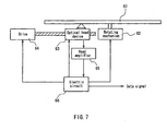
- FIG. 7 shows the schematic configuration of an optical information processing apparatus of this embodiment.
- An optical disk 61 is a disk-shaped optical recording medium and is rotated by a rotating mechanism 62.
- the optical disk 61 has the same configuration as the optical recording medium 1 used in Embodiments 1 to 4.
- An optical head device 63 may be any one of the optical head devices 2 to 5 in Embodiments 1 to 4 and has a fine adjustment means for an objective lens.
- a drive 64 moves the optical head device 63 to a track of the optical disk that contains desired information.
- the optical head device 63 transmits a focus error signal or tracking error signal to an electric circuit 66 in accordance with the positional relationship between the optical head device 63 and the optical disk 61.
- the electric circuit 66 transmits a signal for finely adjusting the objective lens to the optical head device 64.
- the optical head device 64 Upon receiving the signal, the optical head device 64 performs focus servo and tracking servo on the optical disk 61 so that information is read, written, or erased with respect to the optical disk 61.
- the electric circuit 66 also has the functions of adjusting the intensity of a laser beam to optimize a reproduction signal and controlling the size of an aperture formed in the mask layer of the optical disk 61.
- This configuration allows the optical information processing apparatus to perform super-resolution reproduction with improved S/N.
- a Sb film is used as the mask layer 13 of the optical recording medium 1.
- the mask layer 13 is not limited thereto, and may be made of a material whose optical properties are changed reversibly in accordance with light intensity.
- silver oxide, a semiconductor (including elements such as Si and Ge), chalcogenide glass, and a thermochromic material also can be used.
- Ge 30 Sb 15 Te 55 is used as the recording layer 15.
- the recording layer 15 is not limited thereto, and may be made of a material (e.g., various organic dyes or chalcogenide glass) that can record/reproduce information by light.
- the recording layer 13 can be a reflection film on which information is recorded beforehand in concave-concave form.
Abstract
Description
- The present invention relates to an optical information reproducing method, an optical head device, and an optical information processing apparatus for optically reproducing information from optical disks or optical cards.
- In recent years, with the advance of the information society, there has been a growing demand for a large-capacity external storage. For optical information recording, an increase in density by reducing the size of recording pits has been restricted due to a diffraction limit that depends on the wavelength of light and the numerical aperture of an objective lens.
- Therefore, a so-called super-resolution recording/reproducing technology that enables readout of a recording mark smaller than a focusing spot diameter has been proposed as a means for achieving higher density. For example,
JP 2000-348377 -
FIG. 8 shows the cross-sectional configuration of an optical recording medium used in super-resolution recording/reproduction. Thisoptical recording medium 1 includes atransparent substrate 11 and a firstprotective layer 12, amask layer 13, a secondprotective layer 14, arecording layer 15, and a thirdprotective layer 16 that are formed on thetransparent substrate 11 in the indicated order. The first to thirdprotective layers recording layer 15 is made of a phase change material (e.g., a multinary compound such as GeSbTe). Themask layer 13 is made of silver oxide that is decomposed into oxygen and silver by heat. When theoptical recording medium 1 is irradiated with convergent light L1, a focusing spot is formed in themask layer 13, and then the silver oxide is decomposed into oxygen and silver to change the refractive index in a high-temperature portion of the focusing spot where the temperature exceeds a given threshold value. Thus, anaperture 17 smaller than the focusing spot diameter is formed in themask layer 13 as a refractive index changing region. It is possible to write arecording mark 18 into therecording layer 15 or read therecording mark 18 from therecording layer 15 using near-field light generated at theaperture 17. Therecording layer 15 is located at the position where the near-field light generated in themask layer 13 can reach, thereby achieving both high-speed writing and high-speed reading. - A general optical head device has been used in the above super-resolution recording/reproduction.
FIG. 9 shows a generaloptical head device 101 when used for reproducing information from theoptical recording medium 1. For convenience, the lateral direction of the sheet of this drawing is identified as an X-direction, the vertical direction from the sheet surface is identified as a Y-direction, and the longitudinal direction of the sheet is identified as a Z-direction. - A semiconductor laser 102 (a radiation light source) radiates linearly polarized light that is polarized in the X-direction. The light emitted from the
semiconductor laser 102 enters apolarization beam splitter 103. Thepolarization beam splitter 103 has the functions of transmitting all the light polarized in the X-direction and reflecting all the light polarized in the Y-direction. The light passing through thepolarization beam splitter 103 is converted into parallel light by acollimator lens 104, then converted into circularly polarized light by a quarter-wave plate 105, and focused to the inside of theoptical recording medium 1 by anobjective lens 106. The light reflected from theoptical recording medium 1 again passes through theobjective lens 106 and the quarter-wave plate 105, and thus is converted into linearly polarized light that is polarized in the Y-direction. This linearly polarized light further passes through thecollimator lens 104 and enters thepolarization beam splitter 103. The light entering thepolarization beam splitter 103 is polarized in the Y-direction, and therefore is reflected by thepolarization beam splitter 103. The reflected light passes through acylindrical lens 107 or the like so that the wavefront is controlled to detect a servo signal. Subsequently, aphotodetector 108 detects a reproduction signal and a servo signal. The quarter-wave plate 105 and thepolarization beam splitter 103 are used to improve the light utilization efficiency. Even if the quarter-wave plate 105 is not provided, and thepolarization beam splitter 103 is replaced with a non-polarization beam splitter, information can be recorded/reproduced. - When optical information is reproduced in the above manner, a general laser beam includes a noise component. For normal reproduction (rather than the super-resolution reproduction), the noise component is not a problem because the degree of signal modulation is sufficient. In the case of super-resolution reproduction, however, a recording mark smaller than the spot diameter of the laser beam should be read, so that the degree of modulation of a reproduction signal is reduced significantly. Therefore, the effect of the noise component of the laser beam cannot be ignored, which may lead to S/N degradation.
-
EP 0555049 A2 discloses an optical head device comprising a radiation light source, a focusing optical system and a photodetector. -
JP 2000 348377 - An optical information reproducing method of the present invention is used for an optical recording medium. The optical recording medium includes a recording layer containing information and a mask layer that is located close to the recording layer and includes a nonlinear optical material whose optical properties are changed in accordance with incident light intensity. The method includes the following: irradiating the optical recording medium with convergent light that is polarized in a first direction to form an optical property changing region in a portion of a region of the mask layer that is exposed to the convergent light and then to irradiate the recording layer with the light that has passed through the optical property changing region, wherein a diameter of the optical property changing region is smaller than that of a focusing spot of the convergent light and a transmittance of the optical property changing region is changed by the irradiation of the convergent light; and detecting a reproduction signal by using a second polarized component; characterised in that the method further comprises dividing reflected light from the optical recording medium into a first polarized component that is polarized in the first direction and a second polarized component that is polarized in a second direction perpendicular to the first direction.
- An optical information processing apparatus of the present invention includes an optical recording medium and an optical head device. The optical recording medium includes a recording layer containing information and a mask layer that is located close to the recording layer and includes a nonlinear optical material whose optical properties are changed in accordance with incident light intensity. The optical head device includes the following: a radiation light source for radiating linearly polarized light that is polarized in a first direction; a focusing optical system for converging the light emitted from the radiation light source on the optical recording medium to form a tiny spot; a polarization separation optical system for dividing reflected light from the optical recording medium into a first polarized component that is polarized in the first direction and a second polarized component that is polarized in a second direction perpendicular to the first direction; and a photodetector for detecting a reproduction signal by receiving the second polarized component separated by the polarization separation optical system.
-
-
FIG. 1 is a cross-sectional view showing an example of the configuration of an optical recording medium used for super-resolution recording/reproduction. -
FIG. 2 is a cross-sectional view showing how to perform super-resolution recording/reproduction with respect to an optical recording medium. -
FIG. 3 is a schematic diagram showing the configuration of an optical head device inEmbodiment 1 of the present invention. -
FIG. 4 is a schematic diagram showing the configuration of an optical head device inEmbodiment 2 of the present invention. -
FIG. 5 is a schematic diagram showing the configuration of an optical head device inEmbodiment 3 of the present invention. -
FIG. 6 is a schematic diagram showing the configuration of an optical head device inEmbodiment 4 of the present invention. -
FIG. 7 is a schematic diagram showing the configuration of an optical information processing apparatus inEmbodiment 5 of the present invention. -
FIG. 8 is a cross-sectional view showing how to perform super-resolution recording/reproduction with respect to an optical recording medium. -
FIG. 9 is a schematic diagram showing the configuration of a conventional optical head device. - An optical information reproducing method of the present invention is used for an optical recording medium. The optical recording medium includes a recording layer containing information and a mask layer that is located close to the recording layer and includes a nonlinear optical material whose optical properties are changed in accordance with incident light intensity. The method includes the following: irradiating the optical recording medium with convergent light that is polarized in a first direction; forming an optical property changing region in a portion of a region of the mask layer that is exposed to the convergent light; irradiating the recording layer with light passing through the optical property changing region; dividing reflected light from the optical recording medium into a first polarized component that is polarized in the first direction and a second polarized component that is polarized in a second direction perpendicular to the first direction; and detecting a reproduction signal by using the second polarized component. The reflected light from the optical recording medium used in the optical information reproducing method of the present invention includes light reflected from the recording layer and light reflected from the mask layer. The light reflected from the recording layer represents information (including reproduction information) recorded on the recording layer and has a high degree of modulation. The light reflected from the mask layer includes no reproduction information. There is a difference in polarization state between them. Specifically, the light reflected from the mask layer has the same polarization state as the convergent light for irradiation. In contrast, the light reflected from the recording layer is scattered in the optical property changing region of the mask layer, and also includes a polarized component perpendicular to the polarization direction of the convergent light. The optical information reproducing method of the present invention allows the component (the second polarized component), which is polarized in the direction (the second direction) perpendicular to the polarization direction (the first direction) of the irradiation light and is included in light that represents reproduction information and has a high degree of modulation, to be taken out of the reflected light from the optical recording medium and used to detect a reproduction signal. Thus, a reproduction signal with a high degree of modulation can be obtained, and S/N can be improved in super-resolution reproduction.
- In the optical recording medium used in the optical information reproducing method of the present invention, the nonlinear optical material of the mask layer may be at least one selected from antimony (Sb), silver oxide, a semiconductor, chalcogenide glass, and a thermochromic material. As the semiconductor, e.g., a semiconductor including elements such as silicon (Si) and germanium (Ge) can be used. The thermochromic material is a material that reversibly changes in color with temperature.
- In the optical information reproducing method of the present invention, it is desirable that a servo signal is detected by using the first polarized component that is separated from the reflected light from the optical recording medium.
- An optical head device of the present invention is used for reproducing information from an optical recording medium. The optical recording medium includes a recording layer containing the information and a mask layer that is located close to the recording layer and includes a nonlinear optical material whose optical properties are changed in accordance with incident light intensity. The optical head device includes the following: a radiation light source for radiating light that is polarized in a first direction; a focusing optical system for converging the light emitted from the radiation light source on the optical recording medium to form a tiny spot; a polarization separation optical system for dividing reflected light from the optical recording medium into a first polarized component that is polarized in the first direction and a second polarized component that is polarized in a second direction perpendicular to the first direction; and a photodetector for detecting a reproduction signal by receiving the second polarized component separated by the polarization separation optical system. In this case, the reflected light from the optical recording medium includes light that represents information recorded on the recording layer and has a high degree of modulation (the light reflected from the recording layer) and light that includes no reproduction information (the light reflected from the mask layer), as described above. However, the optical head device of the present invention can separate only the light with a high degree of modulation from the reflected light of the optical recording medium and detect a reproduction signal. Thus, S/N can be improved in super-resolution reproduction.
- The polarization separation optical system of the optical head device of the present invention may include, e.g., a polarization beam splitter that transmits all the first polarized component and reflects all the second polarized component or a polarization beam splitter that reflects all the first polarized component and transmits all the second polarized component. Alternatively, the polarization separation optical system may include either a diffraction element that diffracts all the first polarized component and transmits all the second polarized component or a polarizing prism that separates the first polarized component from the second polarized component.
- It is desirable that the optical head device of the present invention further includes a servo signal photodetector that detects a servo signal by receiving the first polarized component separated by the polarization separation optical system.
- An optical information processing apparatus of the present invention includes an optical recording medium and an optical head device. The optical recording medium includes a recording layer containing information and a mask layer that is located close to the recording layer and includes a nonlinear optical material whose optical properties are changed in accordance with incident light intensity. The optical head device includes the following: a radiation light source for radiating linearly polarized light that is polarized in a first direction; a focusing optical system for converging the light emitted from the radiation light source on the optical recording medium to form a tiny spot; a polarization separation optical system for dividing reflected light from the optical recording medium into a first polarized component that is polarized in the first direction and a second polarized component that is polarized in a second direction perpendicular to the first direction; and a photodetector for detecting a reproduction signal by receiving the second polarized component separated by the polarization separation optical system. The reflected light from the optical recording medium in the optical information processing apparatus of the present invention includes light that represents information recorded on the recording layer and has a high degree of modulation (the light reflected from the recording layer) and light that includes no reproduction information (the light reflected from the mask layer). However, the optical information processing apparatus of the present invention can separate only the light with a high degree of modulation from the reflected light of the optical recording medium and detect a reproduction signal. Thus, S/N can be improved in super-resolution reproduction.
- In the optical information processing apparatus of the present invention, the nonlinear optical material of the mask layer of the optical recording medium may be at least one selected from Sb, silver oxide, a semiconductor, chalcogenide glass, and a thermochromic material. As the semiconductor, e.g., a semiconductor including elements such as Si and Ge can be used. The thermochromic material is a material that reversibly changes in color with temperature.
- In the optical information processing apparatus of the present invention, the polarization separation optical system of the optical head device may include, e.g., a polarization beam splitter that transmits all the first polarized component and reflects all the second polarized component or a polarization beam splitter that reflects all the first polarized component and transmits all the second polarized component. Alternatively, the polarization separation optical system may include either a diffraction element that diffracts all the first polarized component and transmits all the second polarized component or a polarizing prism that separates the first polarized component from the second polarized component.
- In the optical information processing apparatus of the present invention, it is desirable that the optical head device further includes a servo signal photodetector that detects a servo signal by receiving the first polarized component separated by the polarization separation optical system.
- Hereinafter, embodiments of the present invention will be described with reference to the drawings.
- First, the configuration of an optical recording medium in this embodiment will be described by referring to
FIG. 1 . Anoptical recording medium 1 of this embodiment includes atransparent substrate 11, a firstprotective layer 12, amask layer 13, a secondprotective layer 14, arecording layer 15, and a thirdprotective layer 16 in the indicated order from the incident side of a laser beam for recording/reproducing information. - The
transparent substrate 11 is made of a material that is transparent or almost transparent to the laser beam, and transmits or substantially transmits the laser beam. Guide grooves for the laser beam preferably are formed in the surface of thetransparent substrate 11.FIG. 1 shows the shape of theoptical recording medium 1 provided with the guide grooves. - The
mask layer 13 includes a nonlinear optical material whose optical properties are changed in accordance with incident light intensity. This embodiment uses a Sb film having a thickness of 20 nm. - The
recording layer 15 is provided to record information and made of a material whose state is changed by light or heat generation resulting from the absorption of light. This embodiment uses a Ge30Sb15Te55 film having a thickness of 15 nm. - The first to third
protective layers mask layer 13 and therecording layer 15 and to adjust the optical properties so that therecording layer 13 can absorb light effectively. In this embodiment, a material obtained by mixing ZnS with 20 mol% of SiO2 is used, and the thicknesses of the first, second, and thirdprotective layers - Next, an optical information reproducing method in this embodiment will be described by referring to
FIG. 2 . To record/reproduce information with respect to theoptical recording medium 1, theoptical recording medium 1 is irradiated with a linearly polarized laser beam L1 that is convergent light focused by an objective lens (not shown). This irradiation light is diffracted by the aperture of the objective lens and has an intensity distribution with a shape close to Gaussian distribution in which the radius of a portion where the intensity is 1/e2 with respect to the central portion is 0.41 λ/NA (λ is the wavelength of a laser beam for irradiation, and NA is the numerical aperture of an objective lens). - In the Sb film (the mask layer 13), the temperature rises in the central portion of a region exposed to the laser beam L1, and the optical properties are changed. Consequently, a region (an optical property changing region) that changes in optical properties is formed in a portion of the region of the
mask layer 13 that is exposed to the laser beam L1. In this portion, the light intensity of the laser beam L1 is larger than a predetermined value. The optical property changing region has a high transmittance with respect to the laser beam L1 and serves as anaperture 17. The size of theaperture 17 is smaller than the spot of the laser beam L1 falling on themask layer 13. - By using a laser beam L2 that is transmitted through the
aperture 17 thus formed in themask layer 13, information is recorded on therecording layer 15 and the information is reproduced from therecording layer 15. The recordable/reproducible minimum mark size is determined by the size of theaperture 17 and independent of the diffraction limit. Accordingly, information of not more than the diffraction limit can be recorded/reproduced, i.e., so-called super-resolution recording/reproduction can be performed. - The information recorded on the
recording layer 15 is reproduced by detecting reflected light L3 of the laser beam L1. The reflected light L3 includes a component of light in the central portion of the spot (i.e., a central light component) L3a (not shown) and a component of light on the periphery of the spot (i.e., a peripheral light component) L3b (not shown). The central light component L3a is light that represents the information recorded on therecording layer 15 and has a high degree of modulation. The peripheral light component L3b is light that is reflected from themask layer 13 before reaching therecording layer 15 and includes no reproduction information. For this reason, when a reproduction signal is detected from the whole of the reflected light L3, the degree of signal modulation is reduced, and S/N is degraded. - Therefore, the optical information reproducing method of the present invention allows the central light component L3a to be taken out of the reflected light L3 and detected as a reproduction signal, thus performing favorable reproduction with an improved degree of signal modulation. In the optical information reproducing method of the present invention, a difference in polarization between the central light component L3a and the peripheral light component L3b is utilized to remove the peripheral light component L3b from the reflected light L3. Since the peripheral light component L3b is reflected from the
mask layer 13, the polarization direction is the same as that of the laser beam L1. The central light component L3a is scattered while passing through theaperture 17, and also includes a polarized component perpendicular to the laser beam L1. Therefore, when the polarized component perpendicular to the laser beam L1 is taken out of the reflected light L3 and detected, a reproduction signal having a high degree of modulation can be obtained. This makes it possible to reduce the effect of noise and improve S/N. - Next, an example of an optical head device used in the optical information reproducing method of the present invention will be described.
FIG. 3 shows anoptical head device 2 of this embodiment when used for reproducing information from theoptical recording medium 1. For convenience, the lateral direction of the sheet of this drawing is identified as an X-direction, the vertical direction from the sheet surface is identified as a Y-direction, and the longitudinal direction of the sheet is identified as a Z-direction. - A semiconductor laser 21 (a radiation light source) radiates linearly polarized light that is polarized in the X-direction (a first direction). A laser beam L1 emitted from the
semiconductor laser 21 enters apolarization beam splitter 22. Thepolarization beam splitter 22 has the functions of dividing the light polarized in the X-direction into transmission and reflection at a desired ratio (e.g., a transmittance of 80% and a reflectance of 20% in this embodiment) and reflecting all the light polarized in the Y-direction (a second direction). The laser beam L1 passing through thepolarization beam splitter 22 is converted into parallel light by a collimator lens 23 and focused to the inside of theoptical recording medium 1 by anobjective lens 24. Theoptical recording medium 1 has the structure as shown inFIGS. 1 and 2 . Reflected light L3 that is reflected from theoptical recording medium 1 again passes through theobjective lens 24 and the collimator lens 23, and then enters thepolarization beam splitter 22, where 20% of the light polarized in the X-direction is reflected and all the light polarized in the Y-direction is reflected. The light reflected from thepolarization beam splitter 22 further enters apolarization beam splitter 25 that serves as a polarization separation optical system. Thepolarization beam splitter 25 has the functions of transmitting all the light polarized in the X-direction and reflecting all the light polarized in the Y-direction. Therefore, thepolarization beam splitter 25 can separate the component (a first polarized component) that is polarized in the X-direction from the component (a second polarized component) that is polarized in the Y-direction. - A
photodetector 28 receives the component polarized in the Y-direction and detects a reproduction signal. The light polarized in the X-direction that has passed through thepolarization beam splitter 25 enters ahologram element 26, where the wavefront is transformed so as to detect a servo signal. Then, the light enters aphotodetector 27 that serves as a servo signal photodetector. Thephotodetector 27 includes a plurality of light-receiving regions and can detect servo signals from the signals in each of the light-receiving regions. - As described above, the
optical head device 2 of this embodiment can separate the component that represents recorded information from the reflected light and perform super-resolution reproduction with improved S/N. - In this embodiment, the polarization beam splitter that transmits all the light polarized in the X-direction and reflects all the light polarized in the Y-direction is used as a polarization separation optical system. Needless to say, it is also possible to use a polarization beam splitter that reflects all the light polarized in the X-direction and transmits all the light polarized in the Y-direction.
- The following is an explanation of another embodiment of an optical head device of the present invention.
FIG. 4 shows anoptical head device 3 of this embodiment when used for reproducing information from theoptical recording medium 1. For convenience, the lateral direction of the sheet of this drawing is identified as an X-direction, the vertical direction from the sheet surface is identified as a Y-direction, and the longitudinal direction of the sheet is identified as a Z-direction. - A semiconductor laser 31 (a radiation light source) radiates linearly polarized light that is polarized in the X-direction (a first direction). A laser beam L1 emitted from the
semiconductor laser 31 enters apolarization beam splitter 32. Thepolarization beam splitter 32 has the functions of transmitting all the light polarized in the X-direction and reflecting all the light polarized in the Y-direction (a second direction). The laser beam L1 passing through thepolarization beam splitter 32 is converted into parallel light by acollimator lens 33 and focused to the inside of theoptical recording medium 1 by anobjective lens 34. Theoptical recording medium 1 has the structure as shown inFIGS. 1 and 2 . Reflected light L3 that is reflected from theoptical recording medium 1 again passes through theobjective lens 34 and thecollimator lens 33, and then enters thepolarization beam splitter 32, where all the light polarized in the X-direction (a first polarized component) is transmitted and all the light polarized in the Y-direction (a second polarized component) is reflected. In other words, thepolarization beam splitter 32 functions as a polarization separation optical system that separates the first polarized component and the second polarized component from the reflected light. - A
photodetector 35 receives the component polarized in the Y-direction and detects a reproduction signal. The light polarized in the X-direction that has been separated by thepolarization beam splitter 32 enters ahologram element 36, where the wavefront is transformed by diffraction of thehologram element 36 so as to detect a servo signal. Then, the light enters aphotodetector 37 that serves as a servo signal photodetector. Thephotodetector 37 includes a plurality of light-receiving regions and can detect servo signals from the signals in each of the light-receiving regions. In this configuration, thesemiconductor laser 31 can be located close to thephotodetector 37 for detecting a servo signal, thus improving stability. Moreover, thesemiconductor laser 31, thephotodetector 37, and thehologram element 36 are integrated in the same package, so that the optical head device can have higher stability. - As described above, the
optical head device 3 of this embodiment can separate the component that represents recorded information from the reflected light and perform super-resolution reproduction with improved S/N. - The following is an explanation of another embodiment of an optical head device of the present invention.
FIG. 5 shows anoptical head device 4 of this embodiment when used for reproducing information from theoptical recording medium 1. For convenience, the lateral direction of the sheet of this drawing is identified as an X-direction, the vertical direction from the sheet surface is identified as a Y-direction, and the longitudinal direction of the sheet is identified as a Z-direction. - A semiconductor laser 41 (a radiation light source) radiates linearly polarized light that is polarized in the X-direction (a first direction). A laser beam L1 emitted from the
semiconductor laser 41 enters apolarization beam splitter 42. Thepolarization beam splitter 42 has the functions of dividing the light polarized in the X-direction into transmission and reflection at a desired ratio (e.g., a transmittance of 80% and a reflectance of 20% in this embodiment) and reflecting all the light polarized in the Y-direction (a second direction). The laser beam L1 passing through thepolarization beam splitter 42 is converted into parallel light by a collimator lens 43 and focused to the inside of theoptical recording medium 1 by anobjective lens 44. Theoptical recording medium 1 has the structure as shown inFIGS. 1 and 2 . Reflected light L3 that is reflected from theoptical recording medium 1 again passes through theobjective lens 44 and the collimator lens 43, and then enters thepolarization beam splitter 42, where 20% of the light polarized in the X-direction is reflected and all the light polarized in the Y-direction is reflected. The light reflected from thepolarization beam splitter 42 further enters a polarizationanisotropic hologram 45 that serves as a polarization separation optical system. The polarizationanisotropic hologram 45 is a diffraction element that diffracts the component polarized in the X-direction (a first polarized component) at a desired wavefront so as to detect a servo signal and transmits the component polarized in the Y-direction (a second polarized component). Therefore, the polarizationanisotropic hologram 45 can separate the two polarized components. - The component polarized in the Y-direction that has been transmitted through the polarization
anisotropic hologram 45 is detected in a light-receiving region of aphotodetector 46 and converted into a reproduction signal. The component polarized in the X-direction that has been diffracted by the polarizationanisotropic hologram 45 is detected in a plurality of light-receiving regions of thephotodetector 46 and converted into servo signals. In this configuration, thephotodetector 46 is used for a reproduction signal as well as a servo signal. - As described above, the
optical head device 4 of this embodiment can separate the component that represents recorded information from the reflected light and perform super-resolution reproduction with improved S/N. - The following is an explanation of another embodiment of an optical head device of the present invention.
FIG. 6 shows anoptical head device 5 of this embodiment when used for reproducing information from theoptical recording medium 1. For convenience, the lateral direction of the sheet of this drawing is identified as an X-direction, the vertical direction from the sheet surface is identified as a Y-direction, and the longitudinal direction of the sheet is identified as a Z-direction. - A semiconductor laser 51 (a radiation light source) radiates linearly polarized light that is polarized in the X-direction (a first direction). A laser beam L1 emitted from the
semiconductor laser 51 enters apolarization beam splitter 52. Thepolarization beam splitter 52 has the functions of dividing the light polarized in the X-direction into transmission and reflection at a desired ratio (e.g., a transmittance of 80% and a reflectance of 20% in this embodiment) and reflecting all the light polarized in the Y-direction (a second direction). The laser beam L1 passing through thepolarization beam splitter 52 is converted into parallel light by a collimator lens 53 and focused to the inside of theoptical recording medium 1 by anobjective lens 54. Theoptical recording medium 1 has the structure as shown inFIGS. 1 and 2 . Reflected light L3 that is reflected from theoptical recording medium 1 again passes through theobjective lens 54 and the collimator lens 53, and then enters thepolarization beam splitter 52, where 20% of the light polarized in the X-direction is reflected and all the light polarized in the Y-direction is reflected. The light reflected from thepolarization beam splitter 52 further enters a Wollaston prism (a polarizing prism) 55 that serves as a polarization separation optical system, and then is divided into the component polarized in the X-direction (a first polarized component) and the component polarized in the Y-direction (a second polarized component). - The component polarized in the Y-direction that has been separated by the
Wollaston prism 55 is detected in a light-receiving region of aphotodetector 57 and converted into a reproduction signal. The component polarized in the X-direction that has been separated by theWollaston prism 55 is detected in a plurality of light-receiving regions of thephotodetector 57 and converted into servo signals. In this configuration, thephotodetector 57 is used for a reproduction signal as well as a servo signal. - As described above, the
optical head device 5 of this embodiment can separate the component that represents recorded information from the reflected light and perform super-resolution reproduction with improved S/N. - An example of an optical information processing apparatus of the present invention will be described below.
-
FIG. 7 shows the schematic configuration of an optical information processing apparatus of this embodiment. Anoptical disk 61 is a disk-shaped optical recording medium and is rotated by arotating mechanism 62. Theoptical disk 61 has the same configuration as theoptical recording medium 1 used inEmbodiments 1 to 4. Anoptical head device 63 may be any one of theoptical head devices 2 to 5 inEmbodiments 1 to 4 and has a fine adjustment means for an objective lens. Adrive 64 moves theoptical head device 63 to a track of the optical disk that contains desired information. Theoptical head device 63 transmits a focus error signal or tracking error signal to anelectric circuit 66 in accordance with the positional relationship between theoptical head device 63 and theoptical disk 61. In response to these signals, theelectric circuit 66 transmits a signal for finely adjusting the objective lens to theoptical head device 64. Upon receiving the signal, theoptical head device 64 performs focus servo and tracking servo on theoptical disk 61 so that information is read, written, or erased with respect to theoptical disk 61. Theelectric circuit 66 also has the functions of adjusting the intensity of a laser beam to optimize a reproduction signal and controlling the size of an aperture formed in the mask layer of theoptical disk 61. - This configuration allows the optical information processing apparatus to perform super-resolution reproduction with improved S/N.
- In
Embodiment 1 to 4, a Sb film is used as themask layer 13 of theoptical recording medium 1. However, themask layer 13 is not limited thereto, and may be made of a material whose optical properties are changed reversibly in accordance with light intensity. For example, silver oxide, a semiconductor (including elements such as Si and Ge), chalcogenide glass, and a thermochromic material also can be used. Moreover, Ge30Sb15Te55 is used as therecording layer 15. However, therecording layer 15 is not limited thereto, and may be made of a material (e.g., various organic dyes or chalcogenide glass) that can record/reproduce information by light. Therecording layer 13 can be a reflection film on which information is recorded beforehand in concave-concave form.
Claims (9)
- An optical information reproducing method for reproducing information from an optical recording medium (1),
the optical recording medium (1) comprising:a recording layer (15) on which the information is recorded and from which the information is read by reflection intensity of irradiation light; anda mask layer (13) that is located close to the recording layer (15) and includes a nonlinear optical material whose optical properties are changed in accordance with incident light intensity,the method comprising:irradiating the optical recording medium (1) with convergent light that is polarized in a first direction to form an optical property changing region in a portion of a region of the mask layer (13) that is exposed to the convergent light and then toirradiate the recording layer (15) with the light that has passed through the optical property changing region, wherein a diameter of the optical property changing region is smaller than that of a focusing spot of the convergent light and a transmittance of the optical property changing region is changed by the irradiation of the convergent light; anddetecting a reproduction signal by using a second polarized component;characterised in that the method further comprisesdividing reflected light from the optical recording medium (1) into a first polarized component that is polarized in the first direction and the second polarized component that is polarized in a second direction perpendicular to the first direction. - The method according to claim 1, wherein the nonlinear optical material is at least one selected from the group consisting of antimony, silver oxide, a semiconductor, chalcogenide glass, and a thermochromic material.
- The method according to claim 1, wherein a servo signal is detected by using the first polarized component that is separated from the reflected light from the optical recording medium (1).
- An optical information processing apparatus comprising:an optical recording medium (1); andan optical head device (2, 3, 4, 5) for reproducing information from the optical recording medium (1);the optical recording medium (1) comprising:a recording layer (15) on which information is recorded and from which information is read by reflection intensity or irradiation light; anda mask layer (13) that is located close to the recording layer (15) and includes a nonlinear optical material whose optical properties are changed in accordance with incident light intensity;the optical head device (2, 3, 4, 5) comprising:a radiation light source (21, 31, 41, 51) for radiating light that is polarized in a first direction;a focusing optical system for converging the light emitted from the radiation light source (21, 31, 41, 51) on the mask layer (13) to form a tiny spot so that the mask layer (13) is irradiated with convergent light that is polarized in a first direction, forming an optical property changing region in a portion of a region of the mask layer that is exposed to the convergent light, and irradiating the recording layer (15) with light passing through the optical property changing region; anda photodetector (28, 35, 46, 57) for detecting a reproduction signal by receiving a second polarized component separated by a polarization separation optical system (25,32,42,52);characterised in that the device further comprisesa polarization separation optical system (25,32,42,52) for dividing reflected light from the optical recording medium (1) into a first polarized component that is polarized in the first direction and the second polarized component that is generated by scattering in the optical property changing regions and polarized in a second direction perpendicular to the first direction.
- The optical information processing apparatus according to claim 4, wherein the nonlinear optical material is at least one selected from the group consisting of antimony, silver oxide, a semiconductor, chalcogenide glass, and a thermochromic material.
- The optical information processing apparatus according to claim 4, wherein the polarization separation optical system comprises a polarization beam splitter (22, 32, 42, 52) for transmitting all the first polarized component and reflecting all the second polarized component or a polarization beam splitter for reflecting all the first polarized component and transmitting all the second polarized component.
- The optical information processing apparatus according to claim 4, wherein the polarization separation optical system comprises a diffraction element (45) for diffracting all the first polarized component and transmitting all the second polarized component.
- The optical information processing apparatus according to claim 4, wherein the polarization separation optical system comprises a polarizing prism (55) for separating the first polarized component from the second polarized component.
- The optical information processing apparatus according to claim 4, further comprising a photodetector (27, 37) for detecting a servo signal by receiving the first polarized component separated by the polarization separation optical system.
Applications Claiming Priority (3)
| Application Number | Priority Date | Filing Date | Title |
|---|---|---|---|
| JP2001381333 | 2001-12-14 | ||
| JP2001381333 | 2001-12-14 | ||
| PCT/JP2002/010508 WO2003052756A1 (en) | 2001-12-14 | 2002-10-09 | Optical information reproducing method, optical head device, and optical information processor |
Publications (3)
| Publication Number | Publication Date |
|---|---|
| EP1455351A1 EP1455351A1 (en) | 2004-09-08 |
| EP1455351A4 EP1455351A4 (en) | 2007-06-06 |
| EP1455351B1 true EP1455351B1 (en) | 2011-08-17 |
Family
ID=19187323
Family Applications (1)
| Application Number | Title | Priority Date | Filing Date |
|---|---|---|---|
| EP02775308A Expired - Fee Related EP1455351B1 (en) | 2001-12-14 | 2002-10-09 | Optical information reproducing method and optical information processing apparatus |
Country Status (6)
| Country | Link |
|---|---|
| US (1) | US7126883B2 (en) |
| EP (1) | EP1455351B1 (en) |
| JP (1) | JP4234013B2 (en) |
| CN (1) | CN1333397C (en) |
| AU (1) | AU2002343961A1 (en) |
| WO (1) | WO2003052756A1 (en) |
Families Citing this family (8)
| Publication number | Priority date | Publication date | Assignee | Title |
|---|---|---|---|---|
| JP3578214B2 (en) * | 2002-12-09 | 2004-10-20 | オムロン株式会社 | Retro-reflective photoelectric sensor |
| EP1792307A1 (en) * | 2004-09-07 | 2007-06-06 | Koninklijke Philips Electronics N.V. | Optical data carrier with a thermochromic layer |
| KR100565797B1 (en) * | 2004-09-20 | 2006-03-29 | 삼성전자주식회사 | Optical pick-up apparatus for multi recoding/reproducing |
| JP4620631B2 (en) * | 2006-05-16 | 2011-01-26 | 株式会社日立メディアエレクトロニクス | Optical disk drive device |
| JP4763581B2 (en) * | 2006-11-27 | 2011-08-31 | 株式会社日立メディアエレクトロニクス | Optical pickup device |
| FR2915827B1 (en) * | 2007-05-04 | 2010-06-11 | Commissariat Energie Atomique | METHOD AND SYSTEM FOR READING HIGH DENSITY OPTICAL INFORMATION. |
| JP2009058341A (en) * | 2007-08-31 | 2009-03-19 | Sanyo Electric Co Ltd | Beam irradiation device and laser radar |
| ATE528757T1 (en) * | 2008-03-07 | 2011-10-15 | Thomson Licensing | OPTICAL STORAGE MEDIUM WITH MULTI-LEVEL DATA LAYER |
Family Cites Families (14)
| Publication number | Priority date | Publication date | Assignee | Title |
|---|---|---|---|---|
| NL8801327A (en) | 1988-05-24 | 1989-12-18 | Philips Nv | METHOD OF OPTICAL SCANNING OF AN INFORMATION SHEET AND OPTICAL RECORD CARRIERS AND SCANNING DEVICES SUITABLE FOR APPLICATION OF THE METHOD. |
| JPH0724122B2 (en) * | 1989-01-23 | 1995-03-15 | 日本発条株式会社 | Optical head structure for magneto-optical recording device |
| JPH0444650A (en) | 1990-06-11 | 1992-02-14 | Canon Inc | Optical head for magneto-optical reproducing device |
| ATE172048T1 (en) | 1992-02-05 | 1998-10-15 | Canon Kk | MAGNETOPTICAL INFORMATION RECORDING AND PLAYBACKING DEVICE |
| JPH06111330A (en) * | 1992-09-24 | 1994-04-22 | Hitachi Ltd | High-density optical recording and reproducing method, and high-density optical recording medium and high-density optical recording and reproducing device used for the same |
| JPH09245366A (en) * | 1996-03-07 | 1997-09-19 | Nippon Telegr & Teleph Corp <Ntt> | Optical recording/reproducing method and its device |
| JP2910689B2 (en) | 1996-06-20 | 1999-06-23 | 日本電気株式会社 | Light head |
| US6187406B1 (en) * | 1997-03-17 | 2001-02-13 | Kabushiki Kaisha Toshiba | Optical disk and optical disk drive |
| JP2000149258A (en) * | 1998-11-12 | 2000-05-30 | Victor Co Of Japan Ltd | Recording and reproducing device of optical disk |
| US6477118B1 (en) * | 1998-11-27 | 2002-11-05 | Hitachi Maxell, Ltd. | Method and apparatus for recording and reproducing information by applying field in a direction other than the direction of magnetization or the direction to a surface of an information recording medium |
| US6661745B1 (en) | 1999-03-29 | 2003-12-09 | Agency Of Industrial Science And Technology | Optical reproducing and recording method, recording medium, and optical device |
| JP4290279B2 (en) * | 1999-06-04 | 2009-07-01 | 独立行政法人産業技術総合研究所 | Optical sample body and writing and reading method thereof |
| JP4381541B2 (en) | 2000-02-10 | 2009-12-09 | 独立行政法人産業技術総合研究所 | Optical information recording method, optical information recording / reproducing method, and optical information recording / reproducing apparatus |
| US6826131B2 (en) * | 2000-10-11 | 2004-11-30 | Matsushita Electric Industrial Co., Ltd. | Magneto-optical recording medium having multiple magnetic layers |
-
2002
- 2002-10-09 AU AU2002343961A patent/AU2002343961A1/en not_active Abandoned
- 2002-10-09 CN CNB028249143A patent/CN1333397C/en not_active Expired - Fee Related
- 2002-10-09 US US10/498,389 patent/US7126883B2/en not_active Expired - Fee Related
- 2002-10-09 JP JP2003553565A patent/JP4234013B2/en not_active Expired - Fee Related
- 2002-10-09 EP EP02775308A patent/EP1455351B1/en not_active Expired - Fee Related
- 2002-10-09 WO PCT/JP2002/010508 patent/WO2003052756A1/en active Application Filing
Also Published As
| Publication number | Publication date |
|---|---|
| JPWO2003052756A1 (en) | 2005-04-28 |
| CN1630904A (en) | 2005-06-22 |
| EP1455351A1 (en) | 2004-09-08 |
| WO2003052756A1 (en) | 2003-06-26 |
| EP1455351A4 (en) | 2007-06-06 |
| US7126883B2 (en) | 2006-10-24 |
| CN1333397C (en) | 2007-08-22 |
| JP4234013B2 (en) | 2009-03-04 |
| US20050041558A1 (en) | 2005-02-24 |
| AU2002343961A1 (en) | 2003-06-30 |
Similar Documents
| Publication | Publication Date | Title |
|---|---|---|
| US7110180B2 (en) | Diffraction grating, method of fabricating diffraction optical element, optical pickup device, and optical disk drive | |
| EP0936604A1 (en) | Optical pickup device | |
| EP0862166B1 (en) | Method for recording/reproducing information on/from a recording optical disc | |
| EP0539217A2 (en) | Holographic elements for an optical recording system | |
| EP1327977B1 (en) | Optical record medium, optical information processing apparatus, and optical recording/reproducing method | |
| EP1455351B1 (en) | Optical information reproducing method and optical information processing apparatus | |
| JP2919632B2 (en) | Recording and / or reproducing apparatus for optical recording medium | |
| US7813258B2 (en) | Optical information recording medium and optical information reproducing method | |
| KR20060095904A (en) | Optical information reproduction device | |
| US7656777B2 (en) | Optical recording medium, optical information processor, and optical recording/reproducing method | |
| EP1488416A1 (en) | Optical pickup apparatus capable of compensating thickness deviation of optical recording media | |
| US20020122374A1 (en) | Optical recording medium, optical information processing apparatus and optical recording and reproducing method | |
| JP2002329316A (en) | Optical recording medium, optical information processor and optical recording and reproducing device | |
| JP3694943B2 (en) | Optical apparatus and optical pickup | |
| JPH0793797A (en) | Optical head and disk device using the same | |
| EP1515391A1 (en) | Antenna device | |
| JPH11259897A (en) | Optical pickup | |
| KR100595509B1 (en) | Base optical unit in optical disk player | |
| JPH10289480A (en) | Information recording medium |
Legal Events
| Date | Code | Title | Description |
|---|---|---|---|
| PUAI | Public reference made under article 153(3) epc to a published international application that has entered the european phase |
Free format text: ORIGINAL CODE: 0009012 |
|
| 17P | Request for examination filed |
Effective date: 20040625 |
|
| AK | Designated contracting states |
Kind code of ref document: A1 Designated state(s): AT BE BG CH CY CZ DE DK EE ES FI FR GB GR IE IT LI LU MC NL PT SE SK TR |
|
| AX | Request for extension of the european patent |
Extension state: AL LT LV MK RO SI |
|
| A4 | Supplementary search report drawn up and despatched |
Effective date: 20070507 |
|
| 17Q | First examination report despatched |
Effective date: 20070828 |
|
| RAP1 | Party data changed (applicant data changed or rights of an application transferred) |
Owner name: PANASONIC CORPORATION |
|
| GRAP | Despatch of communication of intention to grant a patent |
Free format text: ORIGINAL CODE: EPIDOSNIGR1 |
|
| RTI1 | Title (correction) |
Free format text: OPTICAL INFORMATION REPRODUCING METHOD AND OPTICAL INFORMATION PROCESSING APPARATUS |
|
| GRAS | Grant fee paid |
Free format text: ORIGINAL CODE: EPIDOSNIGR3 |
|
| GRAA | (expected) grant |
Free format text: ORIGINAL CODE: 0009210 |
|
| AK | Designated contracting states |
Kind code of ref document: B1 Designated state(s): DE GB NL |
|
| REG | Reference to a national code |
Ref country code: GB Ref legal event code: FG4D |
|
| REG | Reference to a national code |
Ref country code: DE Ref legal event code: R096 Ref document number: 60240818 Country of ref document: DE Effective date: 20111013 |
|
| REG | Reference to a national code |
Ref country code: NL Ref legal event code: T3 |
|
| PGFP | Annual fee paid to national office [announced via postgrant information from national office to epo] |
Ref country code: NL Payment date: 20111027 Year of fee payment: 10 |
|
| PLBE | No opposition filed within time limit |
Free format text: ORIGINAL CODE: 0009261 |
|
| STAA | Information on the status of an ep patent application or granted ep patent |
Free format text: STATUS: NO OPPOSITION FILED WITHIN TIME LIMIT |
|
| 26N | No opposition filed |
Effective date: 20120521 |
|
| REG | Reference to a national code |
Ref country code: DE Ref legal event code: R097 Ref document number: 60240818 Country of ref document: DE Effective date: 20120521 |
|
| REG | Reference to a national code |
Ref country code: NL Ref legal event code: V1 Effective date: 20130501 |
|
| GBPC | Gb: european patent ceased through non-payment of renewal fee |
Effective date: 20121009 |
|
| PG25 | Lapsed in a contracting state [announced via postgrant information from national office to epo] |
Ref country code: GB Free format text: LAPSE BECAUSE OF NON-PAYMENT OF DUE FEES Effective date: 20121009 Ref country code: DE Free format text: LAPSE BECAUSE OF NON-PAYMENT OF DUE FEES Effective date: 20130501 |
|
| REG | Reference to a national code |
Ref country code: DE Ref legal event code: R119 Ref document number: 60240818 Country of ref document: DE Effective date: 20130501 |
|
| PG25 | Lapsed in a contracting state [announced via postgrant information from national office to epo] |
Ref country code: NL Free format text: LAPSE BECAUSE OF NON-PAYMENT OF DUE FEES Effective date: 20130501 |