EP1454709A1 - Tool changing device which prevents chips adhering to tool - Google Patents
Tool changing device which prevents chips adhering to tool Download PDFInfo
- Publication number
- EP1454709A1 EP1454709A1 EP04005019A EP04005019A EP1454709A1 EP 1454709 A1 EP1454709 A1 EP 1454709A1 EP 04005019 A EP04005019 A EP 04005019A EP 04005019 A EP04005019 A EP 04005019A EP 1454709 A1 EP1454709 A1 EP 1454709A1
- Authority
- EP
- European Patent Office
- Prior art keywords
- tool
- motor
- tool changing
- driving
- drive motor
- Prior art date
- Legal status (The legal status is an assumption and is not a legal conclusion. Google has not performed a legal analysis and makes no representation as to the accuracy of the status listed.)
- Granted
Links
- 238000003754 machining Methods 0.000 claims description 18
- 238000000034 method Methods 0.000 claims description 18
- 239000002826 coolant Substances 0.000 description 10
- 238000005520 cutting process Methods 0.000 description 7
- 239000007788 liquid Substances 0.000 description 3
- 238000004140 cleaning Methods 0.000 description 2
- 239000000428 dust Substances 0.000 description 2
- 230000002265 prevention Effects 0.000 description 2
- 230000002411 adverse Effects 0.000 description 1
- 238000010276 construction Methods 0.000 description 1
- 230000006866 deterioration Effects 0.000 description 1
- 230000000694 effects Effects 0.000 description 1
- 230000004048 modification Effects 0.000 description 1
- 238000012986 modification Methods 0.000 description 1
Images



Classifications
-
- B—PERFORMING OPERATIONS; TRANSPORTING
- B23—MACHINE TOOLS; METAL-WORKING NOT OTHERWISE PROVIDED FOR
- B23Q—DETAILS, COMPONENTS, OR ACCESSORIES FOR MACHINE TOOLS, e.g. ARRANGEMENTS FOR COPYING OR CONTROLLING; MACHINE TOOLS IN GENERAL CHARACTERISED BY THE CONSTRUCTION OF PARTICULAR DETAILS OR COMPONENTS; COMBINATIONS OR ASSOCIATIONS OF METAL-WORKING MACHINES, NOT DIRECTED TO A PARTICULAR RESULT
- B23Q3/00—Devices holding, supporting, or positioning work or tools, of a kind normally removable from the machine
- B23Q3/155—Arrangements for automatic insertion or removal of tools, e.g. combined with manual handling
- B23Q3/1552—Arrangements for automatic insertion or removal of tools, e.g. combined with manual handling parts of devices for automatically inserting or removing tools
- B23Q3/1554—Transfer mechanisms, e.g. tool gripping arms; Drive mechanisms therefore
-
- B—PERFORMING OPERATIONS; TRANSPORTING
- B23—MACHINE TOOLS; METAL-WORKING NOT OTHERWISE PROVIDED FOR
- B23Q—DETAILS, COMPONENTS, OR ACCESSORIES FOR MACHINE TOOLS, e.g. ARRANGEMENTS FOR COPYING OR CONTROLLING; MACHINE TOOLS IN GENERAL CHARACTERISED BY THE CONSTRUCTION OF PARTICULAR DETAILS OR COMPONENTS; COMBINATIONS OR ASSOCIATIONS OF METAL-WORKING MACHINES, NOT DIRECTED TO A PARTICULAR RESULT
- B23Q3/00—Devices holding, supporting, or positioning work or tools, of a kind normally removable from the machine
- B23Q3/155—Arrangements for automatic insertion or removal of tools, e.g. combined with manual handling
- B23Q3/157—Arrangements for automatic insertion or removal of tools, e.g. combined with manual handling of rotary tools
- B23Q3/15713—Arrangements for automatic insertion or removal of tools, e.g. combined with manual handling of rotary tools a transfer device taking a single tool from a storage device and inserting it in a spindle
- B23Q3/1572—Arrangements for automatic insertion or removal of tools, e.g. combined with manual handling of rotary tools a transfer device taking a single tool from a storage device and inserting it in a spindle the storage device comprising rotating or circulating storing means
- B23Q3/15722—Rotary discs or drums
-
- B—PERFORMING OPERATIONS; TRANSPORTING
- B23—MACHINE TOOLS; METAL-WORKING NOT OTHERWISE PROVIDED FOR
- B23Q—DETAILS, COMPONENTS, OR ACCESSORIES FOR MACHINE TOOLS, e.g. ARRANGEMENTS FOR COPYING OR CONTROLLING; MACHINE TOOLS IN GENERAL CHARACTERISED BY THE CONSTRUCTION OF PARTICULAR DETAILS OR COMPONENTS; COMBINATIONS OR ASSOCIATIONS OF METAL-WORKING MACHINES, NOT DIRECTED TO A PARTICULAR RESULT
- B23Q11/00—Accessories fitted to machine tools for keeping tools or parts of the machine in good working condition or for cooling work; Safety devices specially combined with or arranged in, or specially adapted for use in connection with, machine tools
- B23Q11/0042—Devices for removing chips
- B23Q11/0053—Devices for removing chips using the gravity force
-
- B—PERFORMING OPERATIONS; TRANSPORTING
- B23—MACHINE TOOLS; METAL-WORKING NOT OTHERWISE PROVIDED FOR
- B23Q—DETAILS, COMPONENTS, OR ACCESSORIES FOR MACHINE TOOLS, e.g. ARRANGEMENTS FOR COPYING OR CONTROLLING; MACHINE TOOLS IN GENERAL CHARACTERISED BY THE CONSTRUCTION OF PARTICULAR DETAILS OR COMPONENTS; COMBINATIONS OR ASSOCIATIONS OF METAL-WORKING MACHINES, NOT DIRECTED TO A PARTICULAR RESULT
- B23Q3/00—Devices holding, supporting, or positioning work or tools, of a kind normally removable from the machine
- B23Q3/155—Arrangements for automatic insertion or removal of tools, e.g. combined with manual handling
- B23Q3/1552—Arrangements for automatic insertion or removal of tools, e.g. combined with manual handling parts of devices for automatically inserting or removing tools
- B23Q3/15526—Storage devices; Drive mechanisms therefor
- B23Q3/15534—Magazines mounted on the spindle
-
- B—PERFORMING OPERATIONS; TRANSPORTING
- B23—MACHINE TOOLS; METAL-WORKING NOT OTHERWISE PROVIDED FOR
- B23Q—DETAILS, COMPONENTS, OR ACCESSORIES FOR MACHINE TOOLS, e.g. ARRANGEMENTS FOR COPYING OR CONTROLLING; MACHINE TOOLS IN GENERAL CHARACTERISED BY THE CONSTRUCTION OF PARTICULAR DETAILS OR COMPONENTS; COMBINATIONS OR ASSOCIATIONS OF METAL-WORKING MACHINES, NOT DIRECTED TO A PARTICULAR RESULT
- B23Q3/00—Devices holding, supporting, or positioning work or tools, of a kind normally removable from the machine
- B23Q3/155—Arrangements for automatic insertion or removal of tools, e.g. combined with manual handling
- B23Q3/1552—Arrangements for automatic insertion or removal of tools, e.g. combined with manual handling parts of devices for automatically inserting or removing tools
- B23Q3/1554—Transfer mechanisms, e.g. tool gripping arms; Drive mechanisms therefore
- B23Q2003/155414—Transfer mechanisms, e.g. tool gripping arms; Drive mechanisms therefore the transfer mechanism comprising two or more grippers
- B23Q2003/155418—Transfer mechanisms, e.g. tool gripping arms; Drive mechanisms therefore the transfer mechanism comprising two or more grippers the grippers moving together
-
- B—PERFORMING OPERATIONS; TRANSPORTING
- B23—MACHINE TOOLS; METAL-WORKING NOT OTHERWISE PROVIDED FOR
- B23Q—DETAILS, COMPONENTS, OR ACCESSORIES FOR MACHINE TOOLS, e.g. ARRANGEMENTS FOR COPYING OR CONTROLLING; MACHINE TOOLS IN GENERAL CHARACTERISED BY THE CONSTRUCTION OF PARTICULAR DETAILS OR COMPONENTS; COMBINATIONS OR ASSOCIATIONS OF METAL-WORKING MACHINES, NOT DIRECTED TO A PARTICULAR RESULT
- B23Q3/00—Devices holding, supporting, or positioning work or tools, of a kind normally removable from the machine
- B23Q3/155—Arrangements for automatic insertion or removal of tools, e.g. combined with manual handling
- B23Q3/1552—Arrangements for automatic insertion or removal of tools, e.g. combined with manual handling parts of devices for automatically inserting or removing tools
- B23Q3/1554—Transfer mechanisms, e.g. tool gripping arms; Drive mechanisms therefore
- B23Q2003/155414—Transfer mechanisms, e.g. tool gripping arms; Drive mechanisms therefore the transfer mechanism comprising two or more grippers
- B23Q2003/155425—Transfer mechanisms, e.g. tool gripping arms; Drive mechanisms therefore the transfer mechanism comprising two or more grippers pivotable
- B23Q2003/155428—Transfer mechanisms, e.g. tool gripping arms; Drive mechanisms therefore the transfer mechanism comprising two or more grippers pivotable about a common axis
-
- B—PERFORMING OPERATIONS; TRANSPORTING
- B23—MACHINE TOOLS; METAL-WORKING NOT OTHERWISE PROVIDED FOR
- B23Q—DETAILS, COMPONENTS, OR ACCESSORIES FOR MACHINE TOOLS, e.g. ARRANGEMENTS FOR COPYING OR CONTROLLING; MACHINE TOOLS IN GENERAL CHARACTERISED BY THE CONSTRUCTION OF PARTICULAR DETAILS OR COMPONENTS; COMBINATIONS OR ASSOCIATIONS OF METAL-WORKING MACHINES, NOT DIRECTED TO A PARTICULAR RESULT
- B23Q3/00—Devices holding, supporting, or positioning work or tools, of a kind normally removable from the machine
- B23Q3/155—Arrangements for automatic insertion or removal of tools, e.g. combined with manual handling
- B23Q3/1552—Arrangements for automatic insertion or removal of tools, e.g. combined with manual handling parts of devices for automatically inserting or removing tools
- B23Q3/1554—Transfer mechanisms, e.g. tool gripping arms; Drive mechanisms therefore
- B23Q2003/155414—Transfer mechanisms, e.g. tool gripping arms; Drive mechanisms therefore the transfer mechanism comprising two or more grippers
- B23Q2003/155425—Transfer mechanisms, e.g. tool gripping arms; Drive mechanisms therefore the transfer mechanism comprising two or more grippers pivotable
- B23Q2003/155435—Transfer mechanisms, e.g. tool gripping arms; Drive mechanisms therefore the transfer mechanism comprising two or more grippers pivotable and linearly movable
- B23Q2003/155439—Transfer mechanisms, e.g. tool gripping arms; Drive mechanisms therefore the transfer mechanism comprising two or more grippers pivotable and linearly movable along the pivoting axis
-
- Y—GENERAL TAGGING OF NEW TECHNOLOGICAL DEVELOPMENTS; GENERAL TAGGING OF CROSS-SECTIONAL TECHNOLOGIES SPANNING OVER SEVERAL SECTIONS OF THE IPC; TECHNICAL SUBJECTS COVERED BY FORMER USPC CROSS-REFERENCE ART COLLECTIONS [XRACs] AND DIGESTS
- Y02—TECHNOLOGIES OR APPLICATIONS FOR MITIGATION OR ADAPTATION AGAINST CLIMATE CHANGE
- Y02P—CLIMATE CHANGE MITIGATION TECHNOLOGIES IN THE PRODUCTION OR PROCESSING OF GOODS
- Y02P70/00—Climate change mitigation technologies in the production process for final industrial or consumer products
- Y02P70/10—Greenhouse gas [GHG] capture, material saving, heat recovery or other energy efficient measures, e.g. motor control, characterised by manufacturing processes, e.g. for rolling metal or metal working
-
- Y—GENERAL TAGGING OF NEW TECHNOLOGICAL DEVELOPMENTS; GENERAL TAGGING OF CROSS-SECTIONAL TECHNOLOGIES SPANNING OVER SEVERAL SECTIONS OF THE IPC; TECHNICAL SUBJECTS COVERED BY FORMER USPC CROSS-REFERENCE ART COLLECTIONS [XRACs] AND DIGESTS
- Y10—TECHNICAL SUBJECTS COVERED BY FORMER USPC
- Y10T—TECHNICAL SUBJECTS COVERED BY FORMER US CLASSIFICATION
- Y10T483/00—Tool changing
- Y10T483/10—Process
-
- Y—GENERAL TAGGING OF NEW TECHNOLOGICAL DEVELOPMENTS; GENERAL TAGGING OF CROSS-SECTIONAL TECHNOLOGIES SPANNING OVER SEVERAL SECTIONS OF THE IPC; TECHNICAL SUBJECTS COVERED BY FORMER USPC CROSS-REFERENCE ART COLLECTIONS [XRACs] AND DIGESTS
- Y10—TECHNICAL SUBJECTS COVERED BY FORMER USPC
- Y10T—TECHNICAL SUBJECTS COVERED BY FORMER US CLASSIFICATION
- Y10T483/00—Tool changing
- Y10T483/11—Tool changing with safety means
-
- Y—GENERAL TAGGING OF NEW TECHNOLOGICAL DEVELOPMENTS; GENERAL TAGGING OF CROSS-SECTIONAL TECHNOLOGIES SPANNING OVER SEVERAL SECTIONS OF THE IPC; TECHNICAL SUBJECTS COVERED BY FORMER USPC CROSS-REFERENCE ART COLLECTIONS [XRACs] AND DIGESTS
- Y10—TECHNICAL SUBJECTS COVERED BY FORMER USPC
- Y10T—TECHNICAL SUBJECTS COVERED BY FORMER US CLASSIFICATION
- Y10T483/00—Tool changing
- Y10T483/12—Tool changing with means to regulate operation by means of replaceable information supply [e.g., templet, tape, card, etc. ]
-
- Y—GENERAL TAGGING OF NEW TECHNOLOGICAL DEVELOPMENTS; GENERAL TAGGING OF CROSS-SECTIONAL TECHNOLOGIES SPANNING OVER SEVERAL SECTIONS OF THE IPC; TECHNICAL SUBJECTS COVERED BY FORMER USPC CROSS-REFERENCE ART COLLECTIONS [XRACs] AND DIGESTS
- Y10—TECHNICAL SUBJECTS COVERED BY FORMER USPC
- Y10T—TECHNICAL SUBJECTS COVERED BY FORMER US CLASSIFICATION
- Y10T483/00—Tool changing
- Y10T483/15—Tool changing with means to condition or adjust tool or tool support
-
- Y—GENERAL TAGGING OF NEW TECHNOLOGICAL DEVELOPMENTS; GENERAL TAGGING OF CROSS-SECTIONAL TECHNOLOGIES SPANNING OVER SEVERAL SECTIONS OF THE IPC; TECHNICAL SUBJECTS COVERED BY FORMER USPC CROSS-REFERENCE ART COLLECTIONS [XRACs] AND DIGESTS
- Y10—TECHNICAL SUBJECTS COVERED BY FORMER USPC
- Y10T—TECHNICAL SUBJECTS COVERED BY FORMER US CLASSIFICATION
- Y10T483/00—Tool changing
- Y10T483/17—Tool changing including machine tool or component
- Y10T483/1733—Rotary spindle machine tool [e.g., milling machine, boring, machine, grinding machine, etc.]
- Y10T483/1748—Tool changer between spindle and matrix
- Y10T483/1752—Tool changer between spindle and matrix including tool holder pivotable about axis
- Y10T483/1755—Plural tool holders pivotable about common axis
-
- Y—GENERAL TAGGING OF NEW TECHNOLOGICAL DEVELOPMENTS; GENERAL TAGGING OF CROSS-SECTIONAL TECHNOLOGIES SPANNING OVER SEVERAL SECTIONS OF THE IPC; TECHNICAL SUBJECTS COVERED BY FORMER USPC CROSS-REFERENCE ART COLLECTIONS [XRACs] AND DIGESTS
- Y10—TECHNICAL SUBJECTS COVERED BY FORMER USPC
- Y10T—TECHNICAL SUBJECTS COVERED BY FORMER US CLASSIFICATION
- Y10T483/00—Tool changing
- Y10T483/17—Tool changing including machine tool or component
- Y10T483/1733—Rotary spindle machine tool [e.g., milling machine, boring, machine, grinding machine, etc.]
- Y10T483/1748—Tool changer between spindle and matrix
- Y10T483/1752—Tool changer between spindle and matrix including tool holder pivotable about axis
- Y10T483/1755—Plural tool holders pivotable about common axis
- Y10T483/1757—Plural tool holders pivotable about common axis including intermediate tool changer
- Y10T483/176—Intermediate tool changer includes tool holder pivotable about axis
-
- Y—GENERAL TAGGING OF NEW TECHNOLOGICAL DEVELOPMENTS; GENERAL TAGGING OF CROSS-SECTIONAL TECHNOLOGIES SPANNING OVER SEVERAL SECTIONS OF THE IPC; TECHNICAL SUBJECTS COVERED BY FORMER USPC CROSS-REFERENCE ART COLLECTIONS [XRACs] AND DIGESTS
- Y10—TECHNICAL SUBJECTS COVERED BY FORMER USPC
- Y10T—TECHNICAL SUBJECTS COVERED BY FORMER US CLASSIFICATION
- Y10T483/00—Tool changing
- Y10T483/18—Tool transfer to or from matrix
- Y10T483/1873—Indexing matrix
-
- Y—GENERAL TAGGING OF NEW TECHNOLOGICAL DEVELOPMENTS; GENERAL TAGGING OF CROSS-SECTIONAL TECHNOLOGIES SPANNING OVER SEVERAL SECTIONS OF THE IPC; TECHNICAL SUBJECTS COVERED BY FORMER USPC CROSS-REFERENCE ART COLLECTIONS [XRACs] AND DIGESTS
- Y10—TECHNICAL SUBJECTS COVERED BY FORMER USPC
- Y10T—TECHNICAL SUBJECTS COVERED BY FORMER US CLASSIFICATION
- Y10T483/00—Tool changing
- Y10T483/18—Tool transfer to or from matrix
- Y10T483/1873—Indexing matrix
- Y10T483/1882—Rotary disc
-
- Y—GENERAL TAGGING OF NEW TECHNOLOGICAL DEVELOPMENTS; GENERAL TAGGING OF CROSS-SECTIONAL TECHNOLOGIES SPANNING OVER SEVERAL SECTIONS OF THE IPC; TECHNICAL SUBJECTS COVERED BY FORMER USPC CROSS-REFERENCE ART COLLECTIONS [XRACs] AND DIGESTS
- Y10—TECHNICAL SUBJECTS COVERED BY FORMER USPC
- Y10T—TECHNICAL SUBJECTS COVERED BY FORMER US CLASSIFICATION
- Y10T483/00—Tool changing
- Y10T483/19—Miscellaneous
Definitions
- the present invention relates to a tool changing device of a machine tool.
- a coolant liquid is supplied to a cutting point of a workpiece being cut by the tool.
- the cutting point may be covered by coolant sprayed as a curtain.
- the chips may be scattered with the coolant and may adhere, with the coolant, to some parts of the machine tool during processing. If the chips adhere to a tapered portion of the tool, it may be difficult to exchange the tool with another tool, and the forming accuracy may deteriorate after the tool is changed.
- Japanese Patent Publication (Kokai) No. 2002-273640 discloses a cleaning device, for a machine tool, which can remove chips adhered to a tapered portion of a tool by jetting a coolant liquid during changing the tool.
- Japanese Patent Publication (Kokai) No. 8-174372 discloses a chip removing device having a vibrator for vibrating a chip cover, in order to remove chips deposited on a chip cover arranged to prevent the chips or a dust adhering to a sliding surface of a machine tool and/or a shaft drive member.
- the proposed devices for removing the chips have a problem that a coolant supplying unit or a mechanism such as a vibrator for removing the chips must be installed, additionally, on the machine tool.
- the device disclosed in the above Japanese Patent Publication (Kokai) No. 8-174372 can remove the chips or the dust deposited on the chip cover by the vibrator positioned on the opposite side of the chip cover in relation to a cutting area. Therefore, the device cannot remove the chips adhered to the tapered portion of the tool.
- the chips are prevented from adhering to the tool, e.g., a tapered portion of the tool, and/or the chips adhered to the tool are removed, without using any additional device.
- the invention may be performed as an aspect of a method for preventing chips from adhering and an aspect of a tool changing device.
- the method for preventing chips from adhering according to the invention can be performed as a first embodiment applied to a tool magazine and a second embodiment applied to a tool changing arm.
- a method for preventing chips adhering to a tool held in a tool magazine of a tool changing device of a machine tool comprising a tool magazine drive motor for indexing the tool magazine, the method comprising; holding the tool in the tool magazine; and vibratory driving of the tool magazine drive motor to vibrate the tool magazine in order to vibrate the tool.
- the vibratory driving of the tool magazine drive motor may be performed during a non-machining period of the machine tool. Further, the vibratory driving of the tool magazine drive motor can be performed by the motor such that the motor performs a forward and a reverse rotation alternately in a certain cycle or the motor performs a rotation and a pause alternately in a certain cycle.
- a method for preventing chips adhering to a tool held by a tool changing arm of a tool changing device of a machine tool comprising a tool changing arm drive motor for rotating the tool changing arm
- the method comprising; holding the tool by the tool changing arm; and vibratory driving of the tool changing arm drive motor to vibrate the tool changing arm in order to vibrate the tool.
- the vibratory driving of the tool changing arm drive motor is performed during a non-machining period of the machine tool. Further, the vibratory driving of the tool changing arm drive motor can be performed such that the motor performs a forward and a reverse rotation alternately in a certain cycle or the motor performs a rotation and a pause alternately in a certain cycle.
- the tool changing device according to the invention also can be performed as a first embodiment applied to a tool magazine and a second embodiment applied to a tool changing arm.
- a tool changing device of a machine tool comprising; a tool magazine; a tool magazine drive motor for indexing the tool magazine; and a tool magazine control for controlling driving of the tool magazine drive motor; the tool magazine control can control driving of the motor such that the motor performs a forward and a reverse rotation alternately or performs a rotation and a pause alternately in a certain cycle so as to vibrate the tool magazine.
- the tool magazine control can control the driving of the motor during a non-machining period of the machine tool.
- a tool changing device of a machine tool comprising; a tool changing arm; a tool changing arm drive motor for rotating the tool changing arm; and a tool changing arm control for controlling driving of the tool changing arm drive motor; the tool changing arm control can control driving of the motor such that the motor performs a forward and a reverse rotation alternately in a certain cycle or performs a rotation and a pause alternately so as to vibrate the tool changing arm.
- the tool changing arm control can control the driving of the motor during a non-machining period of the machine tool.
- Fig. 1 shows a scheme for explaining a tool changing device of the invention. In addition, the construction of a machine tool is omitted in Fig. 1.
- a machine tool performs machining, such as cutting, by mounting a selected tool 20 on a machining spindle 11 and driving the spindle 11 by a machining drive 12.
- the mounting of the tool 20 on the spindle 11 is performed through a tapered portion 21 arranged on the tool 20.
- This tool driving system for the tool 20 depicted in Fig. 1 is merely an example and, therefore, the system may use other configuration.
- a tool changing device 1 includes a tool magazine 2 holding a plurality of tools 20, and a tool changing arm 6.
- the tool changing device 1 takes out a tool suitable for a object to be machined or a machining manner, from among the plurality of tools 20 held in the tool magazine 2, and replace a tool attached to the spindle 11 with the selected tool using the changing arm 6.
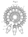
- Fig. 2 and 3 are a schematic top view and a side cross-sectional view of the tool magazine 2, respectively.
- the tool magazine 2 includes a plurality of holding parts 3 on a periphery of a circle, the center of which is coincide with a rotation axis of the magazine 2.
- the rotation axis is rotatable by a tool magazine drive motor 4, whereby indexing the magazine 2 to a desired rotational position can be performed.
- the indexing of the tool magazine 2 means determining the rotational position of the magazine 2 so as to the selected tool can be received by the changing arm 6.
- the indexing can be performed by controlling the rotational position of the tool magazine drive motor 4.
- Fig. 4 is a schematic side cross-sectional view of the tool changing arm 6.
- the changing arm 6 As the changing arm 6 is connected to a revolving shaft 8 rotatable by a tool changing arm drive motor 9, the changing arm 6 may stop at a desired rotational position.
- a tool gripping part 7 arranged on the changing arm 6 can be positioned to a position aligned with the tool magazine 2 or the spindle 11.
- the operation of the tool magazine drive motor 4 is controlled by a tool magazine control 5, and the operation of the tool changing arm drive motor 9 is controlled by a tool magazine control 10.
- the tool magazine 2 is rotated to a rotational position where the selected tool 20 can be received by the changing arm 6.
- the tool changing arm 6 is also rotated by the tool changing arm drive motor 9 via the revolving shaft 8 so that the gripping part 7 of the arm 6 is aligned with a changing position.
- the tool 20 held by the holding part 3 of the tool magazine 2 is gripped by the gripping part 7, then the revolving shaft 8 is rotated so as to move the tool 20 gripped by the gripping part 7 to a position aligned with the spindle 11. Now the spindle 11 can receive the tool 20 from the gripping part 7 of the arm 6. Thus, the tool selected from the tool magazine 2 can be mounted on the spindle 11.
- the gripping part 7 of the changing arm 6 is displaced so as to be aligned with the tool 20 mounted on the spindle 11, then the tool 20 mounted on the spindle 11 is moved to the gripping part 7 of the changing arm 6.
- the tool changing arm 6 is also rotated by the tool changing arm drive motor 9 via the revolving shaft 8 so that the gripping part 7 gripping the tool 20 is displaced to a changing position aligned with the tool magazine 2.
- the tool magazine 2 is also rotated by the tool changing arm drive motor 4 so that a vacant holding part 3 is aligned with a changing position.
- the tool 20 gripped by the gripping part 7 of the arm 6 is moved to the vacant holding part 3 of the magazine 2.
- the tool 20 can be returned to the tool magazine 2.
- the tool magazine control 5 controls the operation of the tool magazine drive motor 4 and performs conventional indexing for determining the rotational position of the tool magazine 2, as described above. Moreover, the tool magazine control 5 can perform a motion control for removing chips adhered to the tapered portion 21 of the tool 20 and/or preventing chips from adhering to the tapered portion 21.
- the prevention of adhering and/or the removing of the chips against the tapered portion 21 can be achieved by vibrating the tool magazine 2 by driving the tool magazine drive motor 4.
- This vibration of the magazine 2 can be achieved, for example, by driving the tool magazine drive motor 4 such that the motor performs a forward and a reverse rotation alternately in a certain cycle or performs a rotation and a pause alternately in a certain cycle.
- the rotation-pause operation of the motor 4 can be performed by the rotation in only one direction and the pause alternately, or by the rotation in one direction and the pause alternately in a certain period and by the rotation in another direction and the pause alternately in a certain period.
- a certain level of vibration is applied to the tool magazine 2, which is not achieved by a constant rotational motion.
- chips adhered to the tool 20, especially to the tapered portion 21 of the tool 20 are shaken and removed from the tool, and/or chips are prevented from adhering to the tapered portion 21.
- Fig. 5 shows a condition in which chips are prevented from adhering to the tapered portion of the tool and/or chips adhered to the tapered portion are removed.
- the tool changing arm control 10 controls the operation of the tool changing arm drive motor 9 and controls a conventional revolving motion determining the rotational position of the tool changing arm 6, as described above. Moreover, the tool changing arm control 10 can perform a motion control for removing chips adhered to the tapered portion 21 of the tool 20 and/or preventing chips from adhering to the tapered portion 21.
- the prevention of adhering and/or the removing of the chips against the tapered portion 21 can be achieved by vibrating the tool changing arm 6 by driving the tool changing arm drive motor 9.
- This vibration of the arm 6 can be achieved, for example, by driving the tool changing arm drive motor 9 such that the motor performs a forward and a reverse rotation alternately in a certain cycle or performs a rotation and a pause alternately in a certain cycle.
- the rotation-pause operation of the motor 9 can be performed by the rotation in only one direction and the pause alternately, or by the rotation in one direction and the pause alternately in a certain period and by the rotation in another direction and the pause alternately in a certain period.
- the vibration can be performed whenever the drive motor 4 or 9 can be vibratory driven, e.g., when the tool magazine drive motor 4 is not performing a usual indexing motion, or the tool changing arm drive motor 9 is not performing a usual revolving motion. Further, the vibration can be performed at regular intervals or for a certain period determined by a program command. For example, the vibration can be applied to the tool for a certain period in order to remove chips adhered to the tool, or for a period as long as possible in order to prevent chips from adhering to the tool.
- the vibration is preferably applied to the tool during a non-machining period of the machine tool, e.g., for the tool magazine, while the machine tool is waiting for machining or is rapid-traversing the tool or the workpiece and, for the tool changing arm, while the machine tool is waiting for machining or changing the tool.
- a non-machining period of the machine tool e.g., for the tool magazine
- the machine tool is waiting for machining or is rapid-traversing the tool or the workpiece and, for the tool changing arm, while the machine tool is waiting for machining or changing the tool.
- the vibration is started with a rapid-traversing of the tool or the workpiece, by a block "G00 Xaaa Yaaa Zaaa Mxxx".
- the vibration started by the start command "Mxxx” is stopped by the stop command "Myyy”.
- the vibration is started by another start command "Mxxx”.
- the vibration is continued for a period of time set by the command "Pzzz”, and is stopped after the period of time passes.
- the tool is changed by a tool changing command "M06Tnnn".
- the tool magazine drive motor and/or the tool changing arm drive motor may be controlled.
- the chips adhered to the tapered portion of the tool of the machine tool can be removed without using any additional device.
Landscapes
- Engineering & Computer Science (AREA)
- Mechanical Engineering (AREA)
- Automatic Tool Replacement In Machine Tools (AREA)
Abstract
Description
- The present invention relates to a tool changing device of a machine tool.
- In a machine tool, in order to improve forming accuracy and extend the lifetime of a tool, a coolant liquid is supplied to a cutting point of a workpiece being cut by the tool. Moreover, in order to prevent cuttings or chips of the workpiece from scattering, the cutting point may be covered by coolant sprayed as a curtain.
- In such a machine tool, the chips may be scattered with the coolant and may adhere, with the coolant, to some parts of the machine tool during processing. If the chips adhere to a tapered portion of the tool, it may be difficult to exchange the tool with another tool, and the forming accuracy may deteriorate after the tool is changed.
- Therefore, Japanese Patent Publication (Kokai) No. 2002-273640 discloses a cleaning device, for a machine tool, which can remove chips adhered to a tapered portion of a tool by jetting a coolant liquid during changing the tool.
- Also, Japanese Patent Publication (Kokai) No. 8-174372 discloses a chip removing device having a vibrator for vibrating a chip cover, in order to remove chips deposited on a chip cover arranged to prevent the chips or a dust adhering to a sliding surface of a machine tool and/or a shaft drive member.
- The proposed devices for removing the chips have a problem that a coolant supplying unit or a mechanism such as a vibrator for removing the chips must be installed, additionally, on the machine tool.
- Also, in the above Japanese Patent Publication (Kokai) No. 2002-273640, it is proposed that an air mixing means for mixing an air flow with a coolant liquid should be used, in order to resolve a problem that, when the viscosity of the coolant is relatively high, the jet force of the coolant is reduced and is not sufficient for cleaning the tapered portion of the tool. Therefore, the air mixing means must be newly installed, as well as the coolant supplying unit, in order to remove the chips adhered to the tapered portion of the tool.
- On the other hand, the device disclosed in the above Japanese Patent Publication (Kokai) No. 8-174372 can remove the chips or the dust deposited on the chip cover by the vibrator positioned on the opposite side of the chip cover in relation to a cutting area. Therefore, the device cannot remove the chips adhered to the tapered portion of the tool.
- It is an object of the present invention to resolve above-mentioned problem in prior art, and to prevent cuttings or chips from adhering to a tool of a machine tool without using any additional device.
- In accordance with the present invention, by using a drive motor with which a tool changing device of the machine tool is usually provided, in order to vibrate the tool, the chips are prevented from adhering to the tool, e.g., a tapered portion of the tool, and/or the chips adhered to the tool are removed, without using any additional device.
- The invention may be performed as an aspect of a method for preventing chips from adhering and an aspect of a tool changing device.
- The method for preventing chips from adhering according to the invention can be performed as a first embodiment applied to a tool magazine and a second embodiment applied to a tool changing arm.
- In accordance with the first embodiment of the method of the present invention, there is provided a method for preventing chips adhering to a tool held in a tool magazine of a tool changing device of a machine tool, the tool changing device comprising a tool magazine drive motor for indexing the tool magazine, the method comprising; holding the tool in the tool magazine; and vibratory driving of the tool magazine drive motor to vibrate the tool magazine in order to vibrate the tool.
- The vibratory driving of the tool magazine drive motor may be performed during a non-machining period of the machine tool. Further, the vibratory driving of the tool magazine drive motor can be performed by the motor such that the motor performs a forward and a reverse rotation alternately in a certain cycle or the motor performs a rotation and a pause alternately in a certain cycle.
- In accordance with the second embodiment of the method of the present invention, there is provided a method for preventing chips adhering to a tool held by a tool changing arm of a tool changing device of a machine tool, the tool changing device comprising a tool changing arm drive motor for rotating the tool changing arm, the method comprising; holding the tool by the tool changing arm; and vibratory driving of the tool changing arm drive motor to vibrate the tool changing arm in order to vibrate the tool.
- The vibratory driving of the tool changing arm drive motor is performed during a non-machining period of the machine tool. Further, the vibratory driving of the tool changing arm drive motor can be performed such that the motor performs a forward and a reverse rotation alternately in a certain cycle or the motor performs a rotation and a pause alternately in a certain cycle.
- The tool changing device according to the invention also can be performed as a first embodiment applied to a tool magazine and a second embodiment applied to a tool changing arm.
- In accordance with the first embodiment of the tool changing device of the present invention, there is provided a tool changing device of a machine tool comprising; a tool magazine; a tool magazine drive motor for indexing the tool magazine; and a tool magazine control for controlling driving of the tool magazine drive motor; the tool magazine control can control driving of the motor such that the motor performs a forward and a reverse rotation alternately or performs a rotation and a pause alternately in a certain cycle so as to vibrate the tool magazine.
- The tool magazine control can control the driving of the motor during a non-machining period of the machine tool.
- In accordance with the second embodiment of the tool changing device of the present invention, there is provided a tool changing device of a machine tool comprising; a tool changing arm; a tool changing arm drive motor for rotating the tool changing arm; and a tool changing arm control for controlling driving of the tool changing arm drive motor; the tool changing arm control can control driving of the motor such that the motor performs a forward and a reverse rotation alternately in a certain cycle or performs a rotation and a pause alternately so as to vibrate the tool changing arm.
- The tool changing arm control can control the driving of the motor during a non-machining period of the machine tool.
- The above and other objects, features and advantages of the present invention will be made more apparent from the following description of the preferred embodiments thereof with reference to the accompanying drawings, wherein:
- Fig. 1 shows a scheme for explaining an embodiment of the present invention;
- Fig. 2 is a schematic top view of an example of a tool magazine;
- Fig. 3 is a schematic side cross-sectional view of the tool magazine;
- Fig. 4 is a schematic side cross-sectional view of an example of a tool changing arm; and
- Fig. 5 is a schematic view illustrating a condition in which chips are prevented from adhering to a tapered portion of the tool and/or chips adhered to the tapered portion are removed.
-
- In the following, embodiments of the invention will be described with reference to the drawings.
- Fig. 1 shows a scheme for explaining a tool changing device of the invention. In addition, the construction of a machine tool is omitted in Fig. 1.
- Referring to the Fig. 1, a machine tool performs machining, such as cutting, by mounting a
selected tool 20 on amachining spindle 11 and driving thespindle 11 by amachining drive 12. The mounting of thetool 20 on thespindle 11 is performed through atapered portion 21 arranged on thetool 20. This tool driving system for thetool 20 depicted in Fig. 1 is merely an example and, therefore, the system may use other configuration. - A tool changing device 1 includes a
tool magazine 2 holding a plurality oftools 20, and atool changing arm 6. The tool changing device 1 takes out a tool suitable for a object to be machined or a machining manner, from among the plurality oftools 20 held in thetool magazine 2, and replace a tool attached to thespindle 11 with the selected tool using the changingarm 6. - Fig. 2 and 3 are a schematic top view and a side cross-sectional view of the
tool magazine 2, respectively. Thetool magazine 2 includes a plurality ofholding parts 3 on a periphery of a circle, the center of which is coincide with a rotation axis of themagazine 2. The rotation axis is rotatable by a toolmagazine drive motor 4, whereby indexing themagazine 2 to a desired rotational position can be performed. The indexing of thetool magazine 2 means determining the rotational position of themagazine 2 so as to the selected tool can be received by the changingarm 6. The indexing can be performed by controlling the rotational position of the toolmagazine drive motor 4. - Fig. 4 is a schematic side cross-sectional view of the
tool changing arm 6. As the changingarm 6 is connected to a revolvingshaft 8 rotatable by a tool changingarm drive motor 9, the changingarm 6 may stop at a desired rotational position. By controlling the tool changingarm drive motor 9 so as to determine the rotational position of theshaft 8, atool gripping part 7 arranged on the changingarm 6 can be positioned to a position aligned with thetool magazine 2 or thespindle 11. - The operation of the tool
magazine drive motor 4 is controlled by atool magazine control 5, and the operation of the tool changingarm drive motor 9 is controlled by atool magazine control 10. - In the tool changing device 1, in order to select a
tool 20 suitable for machining and to mount thetool 20 on thespindle 11, thetool magazine 2 is rotated to a rotational position where theselected tool 20 can be received by the changingarm 6. Thetool changing arm 6 is also rotated by the tool changingarm drive motor 9 via the revolvingshaft 8 so that the grippingpart 7 of thearm 6 is aligned with a changing position. - In this changing position, the
tool 20 held by theholding part 3 of thetool magazine 2 is gripped by thegripping part 7, then the revolvingshaft 8 is rotated so as to move thetool 20 gripped by thegripping part 7 to a position aligned with thespindle 11. Now thespindle 11 can receive thetool 20 from the grippingpart 7 of thearm 6. Thus, the tool selected from thetool magazine 2 can be mounted on thespindle 11. - On the other hand, in order to return the
tool 20 mounted on thespindle 11 to thetool magazine 2, the grippingpart 7 of the changingarm 6 is displaced so as to be aligned with thetool 20 mounted on thespindle 11, then thetool 20 mounted on thespindle 11 is moved to thegripping part 7 of the changingarm 6. Next, thetool changing arm 6 is also rotated by the tool changingarm drive motor 9 via the revolvingshaft 8 so that the grippingpart 7 gripping thetool 20 is displaced to a changing position aligned with thetool magazine 2. Thetool magazine 2 is also rotated by the tool changingarm drive motor 4 so that avacant holding part 3 is aligned with a changing position. - Next, in the changing point, the
tool 20 gripped by thegripping part 7 of thearm 6 is moved to thevacant holding part 3 of themagazine 2. Thus, thetool 20 can be returned to thetool magazine 2. - In the tool changing device 1 of the invention, the
tool magazine control 5 controls the operation of the toolmagazine drive motor 4 and performs conventional indexing for determining the rotational position of thetool magazine 2, as described above. Moreover, thetool magazine control 5 can perform a motion control for removing chips adhered to the taperedportion 21 of thetool 20 and/or preventing chips from adhering to the taperedportion 21. - The prevention of adhering and/or the removing of the chips against the tapered
portion 21 can be achieved by vibrating thetool magazine 2 by driving the toolmagazine drive motor 4. This vibration of themagazine 2 can be achieved, for example, by driving the toolmagazine drive motor 4 such that the motor performs a forward and a reverse rotation alternately in a certain cycle or performs a rotation and a pause alternately in a certain cycle. The rotation-pause operation of themotor 4 can be performed by the rotation in only one direction and the pause alternately, or by the rotation in one direction and the pause alternately in a certain period and by the rotation in another direction and the pause alternately in a certain period. - By the forward-reverse rotating operation and/or the rotation-pause operation of the tool
magazine drive motor 4, a certain level of vibration is applied to thetool magazine 2, which is not achieved by a constant rotational motion. By this vibration, chips adhered to thetool 20, especially to the taperedportion 21 of thetool 20, are shaken and removed from the tool, and/or chips are prevented from adhering to the taperedportion 21. Fig. 5 shows a condition in which chips are prevented from adhering to the tapered portion of the tool and/or chips adhered to the tapered portion are removed. - Also, in the tool changing device 1 of the invention, the tool changing
arm control 10 controls the operation of the tool changingarm drive motor 9 and controls a conventional revolving motion determining the rotational position of thetool changing arm 6, as described above. Moreover, the tool changingarm control 10 can perform a motion control for removing chips adhered to the taperedportion 21 of thetool 20 and/or preventing chips from adhering to the taperedportion 21. - The prevention of adhering and/or the removing of the chips against the tapered
portion 21 can be achieved by vibrating thetool changing arm 6 by driving the tool changingarm drive motor 9. This vibration of thearm 6 can be achieved, for example, by driving the tool changingarm drive motor 9 such that the motor performs a forward and a reverse rotation alternately in a certain cycle or performs a rotation and a pause alternately in a certain cycle. The rotation-pause operation of themotor 9 can be performed by the rotation in only one direction and the pause alternately, or by the rotation in one direction and the pause alternately in a certain period and by the rotation in another direction and the pause alternately in a certain period. - By the forward-reverse rotating operation and/or the rotation-pause operation of the tool changing
arm drive motor 9, a certain level of vibration is applied to thetool changing arm 6, which is not achieved by a constant rotational motion. By this vibration, chips adhered to thetool 20, especially to the taperedportion 21 of thetool 20, is shaken and removed from the tool, and/or chips are prevented from adhering to the taperedportion 21. - The vibration can be performed whenever the
drive motor magazine drive motor 4 is not performing a usual indexing motion, or the tool changingarm drive motor 9 is not performing a usual revolving motion. Further, the vibration can be performed at regular intervals or for a certain period determined by a program command. For example, the vibration can be applied to the tool for a certain period in order to remove chips adhered to the tool, or for a period as long as possible in order to prevent chips from adhering to the tool. - However, if the vibration is performed during machining, the forming accuracy of the machine tool may deteriorate. Therefore, the vibration is preferably applied to the tool during a non-machining period of the machine tool, e.g., for the tool magazine, while the machine tool is waiting for machining or is rapid-traversing the tool or the workpiece and, for the tool changing arm, while the machine tool is waiting for machining or changing the tool. In such a manner, adverse effects regarding machining motion such a deterioration of the forming accuracy are prevented.
- In the following, an example of programming will be described for vibratory driving the tool magazine drive motor and/or the tool changing arm drive motor by program command, as shown below:
- G00 Xaaa Yaaa Zaaa Mxxx;
- Myyy;
- G01Xmmm ;
- Mxxx Pzzz;
- M06Tnnn;
- A code Mxxx is a M-code for starting the vibration, a code Myyy is a M-code for stopping the vibration and a code Pzzz is a code for setting a vibration time.
-
- The vibration is started with a rapid-traversing of the tool or the workpiece, by a block "G00 Xaaa Yaaa Zaaa Mxxx". The vibration started by the start command "Mxxx" is stopped by the stop command "Myyy". After the tool or the workpiece is fed by the cutting feed command "G01Xmmm", the vibration is started by another start command "Mxxx". The vibration is continued for a period of time set by the command "Pzzz", and is stopped after the period of time passes. After the vibration is stopped, the tool is changed by a tool changing command "M06Tnnn". In addition, by the above M-codes for starting and stopping the vibration, the tool magazine drive motor and/or the tool changing arm drive motor may be controlled.
- As described above, the chips adhered to the tapered portion of the tool of the machine tool can be removed without using any additional device.
- While the invention has been described with reference to specific embodiments chosen for the purpose of illustration, it should be apparent that numerous modification could be made thereto by those skilled in the art without departing from the basic concept and scope of the invention.
Claims (16)
- A method for preventing chips adhering to a tool held in a tool magazine of a tool changing device of a machine tool, the tool changing device comprising a tool magazine drive motor for indexing the tool magazine, the method comprises:holding the tool in the tool magazine;vibratory driving of the tool magazine drive motor to vibrate the tool magazine in order to vibrate the tool.
- A method as set forth in claim 1, wherein the vibratory driving of the tool magazine drive motor is performed during a non-machining period of the machine tool.
- A method as set forth in claim 1, wherein the vibratory driving of the tool magazine drive motor comprises driving the motor such that the motor performs a forward and a reverse rotation alternately in a certain cycle.
- A method as set forth in claim 1, wherein the vibratory driving of the tool magazine drive motor comprises driving the motor such that the motor performs a rotation and a pause alternately in a certain cycle.
- A method for preventing chips adhering to a tool held by a tool changing arm of a tool changing device of a machine tool, the tool changing device comprising a tool changing arm drive motor for rotating the tool changing arm, the method comprises:holding the tool by the tool changing arm;vibratory driving of the tool changing arm drive motor to vibrate the tool changing arm in order to vibrate the tool.
- A method as set forth in claim 5, wherein the vibratory driving of the tool changing arm drive motor is performed during a non-machining period of the machine tool.
- A method as set forth in claim 5, wherein the vibratory driving of the tool changing arm drive motor comprises driving the motor such that the motor performs a forward and a reverse rotation alternately in a certain cycle.
- A method as set forth in claim 5, wherein the vibratory driving of the tool changing arm drive motor comprises driving the motor such that the motor performs a rotation and a pause alternately in a certain cycle.
- A tool changing device of a machine tool comprising:a tool magazine;a tool magazine drive motor for indexing the tool magazine; anda tool magazine control for controlling driving of the tool magazine drive motor;the tool magazine control can control driving of the tool magazine drive motor such that the motor is vibratory driven so as to vibrate the tool magazine.
- A tool changing device as set forth in claim 9, wherein the tool magazine control can control the driving of the motor during a non-machining period of the machine tool.
- A tool changing device as set forth in claim 9, wherein the tool magazine control can control the driving of the motor such that the motor performs a forward and a reverse rotation alternately in a certain cycle.
- A tool changing device as set forth in claim 9, wherein the tool magazine control can control the driving of the motor such that the motor performs a rotation and a pause alternately in a certain cycle.
- A tool changing device of a machine tool comprising:a tool changing arm;a tool changing arm drive motor for rotating the tool changing arm; anda tool changing arm control for controlling driving of the tool changing arm drive motor;the tool changing arm control can control driving of the tool changing arm drive motor such that the motor is vibratory driven so as to vibrate the tool changing arm.
- A tool changing device as set forth in claim 13, wherein the tool changing arm control can control the driving of the motor during a non-machining period of the machine tool.
- A tool changing device as set forth in claim 13, wherein the tool changing arm control can control the driving of the motor such that the motor performs a forward and a reverse rotation alternately in a certain cycle.
- A tool changing device as set forth in claim 13, wherein the tool changing arm control can control the driving of the motor such that the motor performs a rotation and a pause alternately in a certain cycle.
Applications Claiming Priority (2)
| Application Number | Priority Date | Filing Date | Title |
|---|---|---|---|
| JP2003060428 | 2003-03-06 | ||
| JP2003060428A JP3764432B2 (en) | 2003-03-06 | 2003-03-06 | Tool chip prevention / removal method and tool changer |
Publications (2)
| Publication Number | Publication Date |
|---|---|
| EP1454709A1 true EP1454709A1 (en) | 2004-09-08 |
| EP1454709B1 EP1454709B1 (en) | 2005-09-21 |
Family
ID=32821221
Family Applications (1)
| Application Number | Title | Priority Date | Filing Date |
|---|---|---|---|
| EP04005019A Expired - Lifetime EP1454709B1 (en) | 2003-03-06 | 2004-03-03 | Tool changing device which prevents chips adhering to tool |
Country Status (5)
| Country | Link |
|---|---|
| US (1) | US7150705B2 (en) |
| EP (1) | EP1454709B1 (en) |
| JP (1) | JP3764432B2 (en) |
| CN (1) | CN1287949C (en) |
| DE (1) | DE602004000091T2 (en) |
Cited By (1)
| Publication number | Priority date | Publication date | Assignee | Title |
|---|---|---|---|---|
| ITPI20120086A1 (en) * | 2012-07-30 | 2014-01-31 | Machinale S R L Fab | DEVICE FOR UNLOCKING A TOOL OF A MACHINE TOOL |
Families Citing this family (10)
| Publication number | Priority date | Publication date | Assignee | Title |
|---|---|---|---|---|
| KR100724237B1 (en) | 2004-12-28 | 2007-05-31 | 삼성코닝정밀유리 주식회사 | Scoring wheel unit auto-changing apparatus for use in an oriental cutting machine |
| DE602007000987D1 (en) * | 2006-03-27 | 2009-06-10 | Fanuc Ltd | Apparatus and method for automatically changing the tool for a numerically controlled machine tool |
| TWI310331B (en) * | 2007-05-18 | 2009-06-01 | Ying Sun | Position structure of power source of cutter for a drilling and tapping machine |
| DE102007040157A1 (en) * | 2007-08-24 | 2009-02-26 | Siemens Ag | Method and device for transporting an object |
| EP2045036A1 (en) * | 2007-10-04 | 2009-04-08 | Siemens Aktiengesellschaft | Tool change device with a direct drive reciprocating and pivoting actuator |
| JP6279432B2 (en) * | 2014-08-26 | 2018-02-14 | Dmg森精機株式会社 | Tool changing method and tool changing device |
| JP6688829B2 (en) | 2018-04-04 | 2020-04-28 | Dmg森精機株式会社 | Machine Tools |
| CN109201256B (en) * | 2018-10-24 | 2020-11-10 | 马鞍山市新桥工业设计有限公司 | Cutter clamping device for rice production |
| DE112020006576T5 (en) * | 2020-03-24 | 2022-12-01 | Mitsubishi Electric Corporation | Numerical control unit |
| CN114951844B (en) * | 2021-12-21 | 2025-03-14 | 浙江振兴阿祥集团有限公司 | A high-precision gear hobbing machine that is convenient for gear alignment |
Citations (3)
| Publication number | Priority date | Publication date | Assignee | Title |
|---|---|---|---|---|
| JPH08174372A (en) * | 1994-12-26 | 1996-07-09 | Okuma Mach Works Ltd | Chip removing device for chip cover |
| EP0855245A1 (en) * | 1997-01-28 | 1998-07-29 | Chiron-Werke GmbH & Co. KG | Machine-tool with a flush device |
| JP2002273640A (en) * | 2001-03-19 | 2002-09-25 | Brother Ind Ltd | Machine tool cleaning equipment and machine tools |
Family Cites Families (11)
| Publication number | Priority date | Publication date | Assignee | Title |
|---|---|---|---|---|
| US3691655A (en) * | 1970-01-15 | 1972-09-19 | Toyoda Machine Works Ltd | Machine tool with tool change device |
| JPS4939597B1 (en) * | 1970-12-04 | 1974-10-26 | ||
| US3932924A (en) * | 1971-07-16 | 1976-01-20 | Doall Company | Method of changing tools |
| JPS5845839A (en) * | 1981-09-14 | 1983-03-17 | Fanuc Ltd | Automatic interchanging device for machine tool |
| ATE40862T1 (en) * | 1982-09-28 | 1989-03-15 | Yang Tai Her | MACHINE TOOL. |
| JPH0577129A (en) * | 1991-04-19 | 1993-03-30 | Akihiko Makabe | Tool exchanging method for wet type machine tool using rotary tool |
| US5424621A (en) * | 1993-08-03 | 1995-06-13 | Industrial Technology Research Institute | Parallel conjugate cam type tool magazine mechanism |
| US5735029A (en) * | 1996-12-12 | 1998-04-07 | Western Atlas, Inc. | Flexible arbor mill machine |
| JPH1142527A (en) * | 1997-07-30 | 1999-02-16 | Toshiba Mach Co Ltd | Method of detaching tool from main spindle in machine tool with automatic tool changer, and machine tool |
| JPH11138377A (en) * | 1997-11-13 | 1999-05-25 | Toshiba Mach Co Ltd | Automatic tool replacement device |
| JP2004338036A (en) * | 2003-05-15 | 2004-12-02 | Yamazaki Mazak Corp | Combined machining lathe |
-
2003
- 2003-03-06 JP JP2003060428A patent/JP3764432B2/en not_active Expired - Fee Related
-
2004
- 2004-03-03 DE DE602004000091T patent/DE602004000091T2/en not_active Expired - Fee Related
- 2004-03-03 EP EP04005019A patent/EP1454709B1/en not_active Expired - Lifetime
- 2004-03-05 US US10/792,792 patent/US7150705B2/en not_active Expired - Fee Related
- 2004-03-05 CN CNB2004100077601A patent/CN1287949C/en not_active Expired - Fee Related
Patent Citations (3)
| Publication number | Priority date | Publication date | Assignee | Title |
|---|---|---|---|---|
| JPH08174372A (en) * | 1994-12-26 | 1996-07-09 | Okuma Mach Works Ltd | Chip removing device for chip cover |
| EP0855245A1 (en) * | 1997-01-28 | 1998-07-29 | Chiron-Werke GmbH & Co. KG | Machine-tool with a flush device |
| JP2002273640A (en) * | 2001-03-19 | 2002-09-25 | Brother Ind Ltd | Machine tool cleaning equipment and machine tools |
Non-Patent Citations (2)
| Title |
|---|
| PATENT ABSTRACTS OF JAPAN vol. 1996, no. 11 29 November 1996 (1996-11-29) * |
| PATENT ABSTRACTS OF JAPAN vol. 2003, no. 01 14 January 2003 (2003-01-14) * |
Cited By (1)
| Publication number | Priority date | Publication date | Assignee | Title |
|---|---|---|---|---|
| ITPI20120086A1 (en) * | 2012-07-30 | 2014-01-31 | Machinale S R L Fab | DEVICE FOR UNLOCKING A TOOL OF A MACHINE TOOL |
Also Published As
| Publication number | Publication date |
|---|---|
| JP2004268177A (en) | 2004-09-30 |
| US7150705B2 (en) | 2006-12-19 |
| US20040176228A1 (en) | 2004-09-09 |
| DE602004000091D1 (en) | 2006-02-02 |
| DE602004000091T2 (en) | 2006-07-13 |
| CN1287949C (en) | 2006-12-06 |
| JP3764432B2 (en) | 2006-04-05 |
| CN1526513A (en) | 2004-09-08 |
| EP1454709B1 (en) | 2005-09-21 |
Similar Documents
| Publication | Publication Date | Title |
|---|---|---|
| EP1454709B1 (en) | Tool changing device which prevents chips adhering to tool | |
| JPH10180585A (en) | Machine tools with automatic chip removal equipment | |
| JP6715271B2 (en) | Machine tool controller, machine tool | |
| CN107791094A (en) | Fluid ejection apparatus | |
| KR20080103315A (en) | Cleaning unit for work jig | |
| KR20170142722A (en) | Semiconductor wafer grinder with the same | |
| US5011345A (en) | Contour machining method and apparatus for printed circuit board | |
| US20130134238A1 (en) | Cutting fluid ejection apparatus | |
| JP3775044B2 (en) | Wire saw processing method and wire saw processing apparatus | |
| CN115803147B (en) | Machine tools and their control systems | |
| JP3519536B2 (en) | Spindle device with coolant ejection nozzle and coolant supply cutting method | |
| JP7085076B1 (en) | Machine tools, control methods, and control programs | |
| JPH01281840A (en) | Chip removing device | |
| JP5907716B2 (en) | Tool for cutting tools | |
| JPH08174372A (en) | Chip removing device for chip cover | |
| JP6830731B2 (en) | Cutting equipment | |
| JPH11138306A (en) | External finishing turning device | |
| CN206224218U (en) | Tool cleaning device | |
| JP3096763B2 (en) | Cutting and cutting method of semiconductor block | |
| KR100956743B1 (en) | Deburring Robot Hand | |
| JP4831329B2 (en) | Dicing apparatus and dicing method | |
| US20070059115A1 (en) | Drain cleaning apparatus | |
| JP7296849B2 (en) | Cutting device and cutting blade dressing method | |
| JPH09239630A (en) | Processing method | |
| JPH0639662A (en) | Machine tool |
Legal Events
| Date | Code | Title | Description |
|---|---|---|---|
| PUAI | Public reference made under article 153(3) epc to a published international application that has entered the european phase |
Free format text: ORIGINAL CODE: 0009012 |
|
| 17P | Request for examination filed |
Effective date: 20040303 |
|
| AK | Designated contracting states |
Kind code of ref document: A1 Designated state(s): AT BE BG CH CY CZ DE DK EE ES FI FR GB GR HU IE IT LI LU MC NL PL PT RO SE SI SK TR |
|
| AX | Request for extension of the european patent |
Extension state: AL LT LV MK |
|
| GRAP | Despatch of communication of intention to grant a patent |
Free format text: ORIGINAL CODE: EPIDOSNIGR1 |
|
| GRAS | Grant fee paid |
Free format text: ORIGINAL CODE: EPIDOSNIGR3 |
|
| AKX | Designation fees paid |
Designated state(s): DE |
|
| GRAA | (expected) grant |
Free format text: ORIGINAL CODE: 0009210 |
|
| AK | Designated contracting states |
Kind code of ref document: B1 Designated state(s): DE |
|
| RBV | Designated contracting states (corrected) |
Designated state(s): DE |
|
| REF | Corresponds to: |
Ref document number: 602004000091 Country of ref document: DE Date of ref document: 20051027 Kind code of ref document: P |
|
| REF | Corresponds to: |
Ref document number: 602004000091 Country of ref document: DE Date of ref document: 20060202 Kind code of ref document: P |
|
| PLBE | No opposition filed within time limit |
Free format text: ORIGINAL CODE: 0009261 |
|
| STAA | Information on the status of an ep patent application or granted ep patent |
Free format text: STATUS: NO OPPOSITION FILED WITHIN TIME LIMIT |
|
| 26N | No opposition filed |
Effective date: 20060622 |
|
| PGFP | Annual fee paid to national office [announced via postgrant information from national office to epo] |
Ref country code: DE Payment date: 20090226 Year of fee payment: 6 |
|
| PG25 | Lapsed in a contracting state [announced via postgrant information from national office to epo] |
Ref country code: DE Free format text: LAPSE BECAUSE OF NON-PAYMENT OF DUE FEES Effective date: 20101001 |