EP0855245A1 - Machine-tool with a flush device - Google Patents
Machine-tool with a flush device Download PDFInfo
- Publication number
- EP0855245A1 EP0855245A1 EP97119028A EP97119028A EP0855245A1 EP 0855245 A1 EP0855245 A1 EP 0855245A1 EP 97119028 A EP97119028 A EP 97119028A EP 97119028 A EP97119028 A EP 97119028A EP 0855245 A1 EP0855245 A1 EP 0855245A1
- Authority
- EP
- European Patent Office
- Prior art keywords
- tool
- machine tool
- coolant
- spray nozzles
- tool holder
- Prior art date
- Legal status (The legal status is an assumption and is not a legal conclusion. Google has not performed a legal analysis and makes no representation as to the accuracy of the status listed.)
- Ceased
Links
Images

Classifications
-
- B—PERFORMING OPERATIONS; TRANSPORTING
- B23—MACHINE TOOLS; METAL-WORKING NOT OTHERWISE PROVIDED FOR
- B23Q—DETAILS, COMPONENTS, OR ACCESSORIES FOR MACHINE TOOLS, e.g. ARRANGEMENTS FOR COPYING OR CONTROLLING; MACHINE TOOLS IN GENERAL CHARACTERISED BY THE CONSTRUCTION OF PARTICULAR DETAILS OR COMPONENTS; COMBINATIONS OR ASSOCIATIONS OF METAL-WORKING MACHINES, NOT DIRECTED TO A PARTICULAR RESULT
- B23Q13/00—Equipment for use with tools or cutters when not in operation, e.g. protectors for storage
-
- B—PERFORMING OPERATIONS; TRANSPORTING
- B23—MACHINE TOOLS; METAL-WORKING NOT OTHERWISE PROVIDED FOR
- B23Q—DETAILS, COMPONENTS, OR ACCESSORIES FOR MACHINE TOOLS, e.g. ARRANGEMENTS FOR COPYING OR CONTROLLING; MACHINE TOOLS IN GENERAL CHARACTERISED BY THE CONSTRUCTION OF PARTICULAR DETAILS OR COMPONENTS; COMBINATIONS OR ASSOCIATIONS OF METAL-WORKING MACHINES, NOT DIRECTED TO A PARTICULAR RESULT
- B23Q11/00—Accessories fitted to machine tools for keeping tools or parts of the machine in good working condition or for cooling work; Safety devices specially combined with or arranged in, or specially adapted for use in connection with, machine tools
- B23Q11/0042—Devices for removing chips
- B23Q11/005—Devices for removing chips by blowing
-
- B—PERFORMING OPERATIONS; TRANSPORTING
- B23—MACHINE TOOLS; METAL-WORKING NOT OTHERWISE PROVIDED FOR
- B23Q—DETAILS, COMPONENTS, OR ACCESSORIES FOR MACHINE TOOLS, e.g. ARRANGEMENTS FOR COPYING OR CONTROLLING; MACHINE TOOLS IN GENERAL CHARACTERISED BY THE CONSTRUCTION OF PARTICULAR DETAILS OR COMPONENTS; COMBINATIONS OR ASSOCIATIONS OF METAL-WORKING MACHINES, NOT DIRECTED TO A PARTICULAR RESULT
- B23Q11/00—Accessories fitted to machine tools for keeping tools or parts of the machine in good working condition or for cooling work; Safety devices specially combined with or arranged in, or specially adapted for use in connection with, machine tools
- B23Q11/10—Arrangements for cooling or lubricating tools or work
-
- B—PERFORMING OPERATIONS; TRANSPORTING
- B23—MACHINE TOOLS; METAL-WORKING NOT OTHERWISE PROVIDED FOR
- B23Q—DETAILS, COMPONENTS, OR ACCESSORIES FOR MACHINE TOOLS, e.g. ARRANGEMENTS FOR COPYING OR CONTROLLING; MACHINE TOOLS IN GENERAL CHARACTERISED BY THE CONSTRUCTION OF PARTICULAR DETAILS OR COMPONENTS; COMBINATIONS OR ASSOCIATIONS OF METAL-WORKING MACHINES, NOT DIRECTED TO A PARTICULAR RESULT
- B23Q3/00—Devices holding, supporting, or positioning work or tools, of a kind normally removable from the machine
- B23Q3/155—Arrangements for automatic insertion or removal of tools, e.g. combined with manual handling
- B23Q3/1552—Arrangements for automatic insertion or removal of tools, e.g. combined with manual handling parts of devices for automatically inserting or removing tools
- B23Q3/15526—Storage devices; Drive mechanisms therefor
- B23Q3/15534—Magazines mounted on the spindle
-
- B—PERFORMING OPERATIONS; TRANSPORTING
- B23—MACHINE TOOLS; METAL-WORKING NOT OTHERWISE PROVIDED FOR
- B23Q—DETAILS, COMPONENTS, OR ACCESSORIES FOR MACHINE TOOLS, e.g. ARRANGEMENTS FOR COPYING OR CONTROLLING; MACHINE TOOLS IN GENERAL CHARACTERISED BY THE CONSTRUCTION OF PARTICULAR DETAILS OR COMPONENTS; COMBINATIONS OR ASSOCIATIONS OF METAL-WORKING MACHINES, NOT DIRECTED TO A PARTICULAR RESULT
- B23Q3/00—Devices holding, supporting, or positioning work or tools, of a kind normally removable from the machine
- B23Q3/155—Arrangements for automatic insertion or removal of tools, e.g. combined with manual handling
- B23Q3/157—Arrangements for automatic insertion or removal of tools, e.g. combined with manual handling of rotary tools
- B23Q3/15706—Arrangements for automatic insertion or removal of tools, e.g. combined with manual handling of rotary tools a single tool being inserted in a spindle directly from a storage device, i.e. without using transfer devices
Definitions
- the present invention relates to a machine tool a spindle and a tool changing device with several Tool changers for transferring tool holders between their respective magazine position and a working position the spindle.
- a machine tool of the type mentioned above is from the DE 40 31 997 A1 known.
- the known machine tool has one in a headstock rotatably mounted spindle, centric on the front side a holder for tool holders is provided.
- Such tool holders are usually standardized, they have a steep cone, which is complementary to the inclusion in the Spindle is.
- the steep cone closes down thickened collar on which a gripper groove is provided.
- a holding shaft extends below the covenant Tools can be attached.
- Steep cones of this type can also be designed as hollow cone shafts be provided with an upper opening through the pliers segments and the tension cone of a clamping system in the Intervene inside the tapered hollow shaft to insert it into the Move in recording.
- the face contact between the spindle and Tool holder is not primarily done here via the conical Outer surface of the hollow cone shaft but over an upward pointing ring surface of the thickened covenant, the front the spindle comes into face contact when the tool holder is in the recording is withdrawn.
- a sleeve surrounding the spindle provided that move relative to the longitudinal axis of the spindle can be.
- a tool changing device on the sleeve arranged, which comprises a number of tool changers, of each of which carries a tool holder as described above.
- Each tool changer is equipped with a gripper hand which grips the tool changer on the gripper groove.
- the gripper hand is in turn supported on two gripper arms, that form a parallelogram guide.
- One of the gripper arms is with a drive unit consisting of cylinder and piston rod connected, by extending and retracting the piston rod the gripper hand and thus the tool holder carried by it from the magazine position to the working position on the spindle or from the working position back to the magazine position is transferred.
- the tool holders with their are in the magazine position Steep cones or hollow taper shanks are inserted into quivers protect the tool holder from dirt.
- this object is achieved in the aforementioned Machine tool solved in that a flushing device for Rinsing the machine tool in the area of the tool changing device is provided with coolant.
- the inventors of the present application have recognized that that surprisingly the interfering chips not only during the processing of a workpiece but in particular also while replacing a tool holder on it Tool holder. It has been found that with Chips contaminated coolant during the tool change process, so while both the one to be changed as well the tool holder to be replaced is free and unprotected by the working area of the machine tool can be moved from the Tool changing device drips itself and thereby on the Tool holder arrives.
- the flushing device preferably only during a workpiece machining the tool changing device rinsed with coolant.
- the flushing device uses spray nozzles includes the above the magazine position of the tool holder are arranged.
- the spray nozzles are arranged so far up be that also in the area of the magazine position parts of the tool changing device are also cleaned will.
- the spray nozzles ensure good distribution of the coolant and on the other hand limit the coolant consumption, that when using gush feed Coolant would be significantly larger.
- Spray nozzles coolant during the machining of the workpiece fed to the tool changer in the magazine position remove any chips from the existing tool holder, by machining the workpiece in the work area of the Flying machine tool.
- the spray cone is sufficient the spray nozzles but also so far that the tool changer of the tool holder in use is also cleaned. It should also be noted that usually 8, 12, 16 or up to 20 tool changers evenly distributed around the spindle are arranged, the tool changer when using the Tool holder remain on this.
- the flushing device Includes spray nozzles that are connected to one another via a ring line are connected, the ring line preferably in itself is closed and a feed pipe as a coolant connection having.
- each spray nozzle is between two adjacent tool changers is arranged, preferably A common spray nozzle is provided for two tool changers is.
- each tool changer has one fluid-operated drive unit with piston rod and cylinder has, the piston rod at one end with a Gripper arm is connected, and the spray nozzles above the Gripper arms are arranged.
- the spray nozzles are namely arranged where also with existing machine tools enough space to attach the flushing device is available.
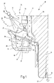
- Fig. 1 10 denotes a machine tool, the one Has spindle 11 with a receptacle 12 for tool holder. Such a tool holder 13 is in Fig. 1 in its Magazine position 15 shown.
- the tool holder 13 has a hollow taper shank 16 which is complementary to the receptacle 12. At the bottom of the Tapered hollow shaft 16 is followed by a thickened collar 17, on which a gripper groove 18 is provided. Furthermore, the federal government 17 an upwardly facing annular surface 19 and one of the Ring surface 19 remote holding shaft 21 for receiving a Tool on. The tool holder comes with its annular surface 19 13 in contact with an end face 22 of the spindle 11, whereby a centered seat with a face contact is provided.
- the machine tool 10 also has a tool changing device 22, which comprises a number of tool changers 25, which are arranged evenly distributed around the spindle 11.
- Each tool changer 25 comprises a gripper hand 26 which Tool holder 13 on the gripper groove 18 holds.
- the gripper hand 26 is attached to two gripper arms 27, 28 which are in themselves known form a parallelogram.
- a quiver 29 is also provided in the the tool holder 13 in its magazine position 15 at least protrudes with its hollow cone 16, whereby the hollow cone shaft is protected from flying chips.
- a drive unit 31 is located above the gripper arms 27, 28 provided a piston rod in a known manner 32 and a cylinder 33 includes.
- the piston rod 32 is with attached its lower end 34 to the gripper arm 27.
- the two gripper arms 27, 28 and each tool changer 25 are attached to a sleeve 35 surrounding the spindle 11, which is displaceable along an arrow indicated at 36.
- a flushing device 37 is provided, which is a ring line 38 comprises, to which at least one spray nozzle 39 is attached.
- This spray nozzle 39 emits a spray cone 41 of coolant, through which the entire tool changing device so during the machining of a workpiece is rinsed, the chips that get into the area of the tool changing device 24 immediately be rinsed off again.
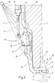
- the piston rod 32 is extended, whereby the Gripper hand 26 pivoted under the spindle 11, as shown in Fig. 2 is shown.
- the sleeve 35 moves in the direction of Arrow 36 down and moves after successful Transfer the tool holder 13 from its magazine position 2 to the working position 53 shown in FIG. whereby the tapered hollow shaft 16 enters the receptacle 12.
- Fig. 2 is a snapshot of this startup of the sleeve 35 shown along arrow 36, where the annular surface 19 still has not come into contact with the end face 22, this does not take place until the sleeve 35 moves further upwards has been.
- the gripper hand 26 remains during processing on the tool holder 13.
- Fig. 2 it can also be seen that the quiver 29 is now through a cover 42 which is arranged on the gripper arm 27, is protected.
- the spray cone 41 of the spray nozzle 39 now sweeps over the entire tool changer 25, so that flying chips themselves cannot start on the tool changer 25.
- FIG. 3 is a plan view of the new machine tool schematically 10, around whose spindle housing 43 the Ring line 38 runs.
- the machine tool 10 comprises a total eight tool changers 25, each between two neighboring ones Tool changer 25, a spray nozzle 39 is provided.
- a supply nozzle 44 for supplying coolant shown. Through this supply nozzle 44 coolant is in the Ring line 38 pressed, which then through the individual spray nozzles 39 is sprayed onto the tool changer 25.
- Fig. 3 it can also be seen that the spray nozzles 39 each are arranged between two flanges 46, 47, wherein between Flanges adjacent spray nozzles 39 a bent piece of pipe 48 runs.
- the entire flushing device 37 comprises eight bent pipe pieces 48 and eight spray nozzles 39, each over the flanges 46, 47 with the adjacent ones Pipe pieces 48 are connected.
- a spray cone is shown again at 41, which here both the tool changer 25a and the tool changer 25b can rinse, so that no second spray nozzle 39 is used could be.
Abstract
Description
Die vorliegende Erfindung betrifft eine Werkzeugmaschine mit einer Spindel und einer Werkzeugwechselvorrichtung mit mehreren Werkzeugwechslern zum Überführen von Werkzeughaltern zwischen deren jeweiliger Magazinposition und einer Arbeitsposition an der Spindel.The present invention relates to a machine tool a spindle and a tool changing device with several Tool changers for transferring tool holders between their respective magazine position and a working position the spindle.
Eine Werkzeugmaschine der vorstehend genannten Art ist aus der DE 40 31 997 A1 bekannt. A machine tool of the type mentioned above is from the DE 40 31 997 A1 known.
Die bekannte Werkzeugmaschine weist eine in einem Spindelstock drehbar gelagerte Spindel auf, an deren Stirnseite zentrisch eine Aufnahme für Werkzeughalter vorgesehen ist.The known machine tool has one in a headstock rotatably mounted spindle, centric on the front side a holder for tool holders is provided.
Derartige Werkzeughalter sind in der Regel genormt, sie weisen einen Steilkegel auf, der komplementär zu der Aufnahme in der Spindel ist. An den Steilkegel schließt sich nach unten ein verdickter Bund an, an dem eine Greifernut vorgesehen ist. Unterhalb des Bundes erstreckt sich ein Halteschaft, an den Werkzeuge befestigt werden können.Such tool holders are usually standardized, they have a steep cone, which is complementary to the inclusion in the Spindle is. The steep cone closes down thickened collar on which a gripper groove is provided. A holding shaft extends below the covenant Tools can be attached.
Beim Einspannen des Werkzeughalters in die Spindel gelangt der Steilkegel in Anlage mit einer konischen Innenfläche der Aufnahme, wobei das Verspannen des Werkzeughalters auf bekannte Weise erfolgt.When the tool holder is clamped in the spindle, the Steep cone in contact with a conical inner surface of the Recording, the clamping of the tool holder on known Way is done.
Derartige Steilkegel können auch als Kegel-Hohlschäfte ausgebildet sein, die mit einer oberen Öffnung versehen sind, durch die Zangensegmente und der Zugkegel eines Spannsystems in das Innere des Kegel-Hohlschaftes eingreifen, um diesen in die Aufnahme einzuziehen. Die Plananlage zwischen Spindel und Werkzeughalter erfolgt hier nicht vorrangig über die konische Außenfläche des Kegel-Hohlschaftes sondern über eine nach oben weisende Ringfläche des verdickten Bundes, die mit der Stirnseite der Spindel in Plananlage kommt, wenn der Werkzeughalter in die Aufnahme eingezogen wird.Steep cones of this type can also be designed as hollow cone shafts be provided with an upper opening through the pliers segments and the tension cone of a clamping system in the Intervene inside the tapered hollow shaft to insert it into the Move in recording. The face contact between the spindle and Tool holder is not primarily done here via the conical Outer surface of the hollow cone shaft but over an upward pointing ring surface of the thickened covenant, the front the spindle comes into face contact when the tool holder is in the recording is withdrawn.
An dem Spindelstock ist eine die Spindel umgebende Hülse vorgesehen, die relativ zu der Längsachse der Spindel verfahren werden kann. An der Hülse ist eine Werkzeugwechselvorrichtung angeordnet, die eine Anzahl von Werkzeugwechslern umfaßt, von denen jeder einen wie oben beschriebenen Werkzeughalter trägt. Dazu ist jeder Werkzeugwechsler mit einer Greiferhand ausgestattet, die den Werkzeugwechsler an der Greifernut erfaßt. Die Greiferhand wiederum ist an zwei Greiferarmen gelagert, die eine Parallelogrammführung bilden. Einer der Greiferarme ist mit einer Antriebseinheit aus Zylinder und Kolbenstange verbunden, wobei durch das Aus- und Einfahren der Kolbenstange die Greiferhand und damit der von ihr getragene Werkzeughalter von der Magazinposition in die Arbeitsposition an der Spindel bzw. von der Arbeitsposition zurück in die Magazinposition überführt wird. Durch eine Längsverschiebung der Hülse und damit des Werkzeugwechslers zu der Spindel wird der Steilkegel bzw. der Kegel-Hohlschaft in die Aufnahme eingeschoben bzw. aus ihr zurückgezogen.On the headstock is a sleeve surrounding the spindle provided that move relative to the longitudinal axis of the spindle can be. There is a tool changing device on the sleeve arranged, which comprises a number of tool changers, of each of which carries a tool holder as described above. Each tool changer is equipped with a gripper hand which grips the tool changer on the gripper groove. The gripper hand is in turn supported on two gripper arms, that form a parallelogram guide. One of the gripper arms is with a drive unit consisting of cylinder and piston rod connected, by extending and retracting the piston rod the gripper hand and thus the tool holder carried by it from the magazine position to the working position on the spindle or from the working position back to the magazine position is transferred. By a longitudinal displacement of the sleeve and thus of the tool changer to the spindle, the steep taper or the tapered hollow shaft inserted or removed from the receptacle withdrawn.
In der Magazinposition sind die Werkzeughalter mit ihren Steilkegeln oder Kegel-Hohlschäften in Köcher eingeführt, die die Werkzeughalter vor Verschmutzung schützen.The tool holders with their are in the magazine position Steep cones or hollow taper shanks are inserted into quivers protect the tool holder from dirt.
Es ist bekannt, daß bei der Bearbeitung eines Werkstückes mit dem Werkzeug, das von dem jeweils in die Aufnahme der Spindel eingespannten Werkzeughalter getragen wird, bei der insoweit beschriebenen Werkzeugmaschine der Arbeitsbereich mit Kühlmittel gespült wird, um zum einen das Werkstück zu kühlen und zum anderen die bei der Bearbeitung entstehenden Späne aus dem Arbeitsbereich des jeweiligen Werkzeuges wegzuspülen und ferner Späne vom Werkzeug und dessen Werkzeughalter zu entfernen. Wie es allgemein bekannt ist, erfolgt dieses Spülen im Bereich der Spindel nur während der Bearbeitung des Werkstückes, während des Werkzeugwechsels ist aus offensichtlichen Gründen keine Spülung erforderlich.It is known that when machining a workpiece with the tool, each of which is in the holder of the spindle clamped tool holder is worn, in so far described machine tool the work area with coolant is rinsed to cool the workpiece on the one hand and others the chips from the Flush away the working area of the respective tool and further Remove chips from the tool and its tool holder. How it is generally known that this rinsing takes place in the area of Spindle only while machining the workpiece while the tool change is not, for obvious reasons Flushing required.
Es hat sich nun herausgestellt, daß offenbar wegen unzureichender Spülung dennoch Späne an dem Steilkegel bzw. Kegel-Hohlschaft hängenbleiben, die in der Magazinstellung des jeweiligen Werkzeughalters an der äußeren Konusfläche und/oder an der Ringfläche des verdickten Bundes antrocknen. Bei dem nächsten Einspannen eines derart verschmutzten Werkzeughalters in die Aufnahme der Spindel kommt es dann insbesondere bei Werkzeughaltern mit Kegel-Hohlschaft zu Fehlern bei der Plananlage, so daß das Werkzeug nicht zentrisch und fluchtend zu der Spindelachse eingespannt wird.It has now turned out that apparently because of insufficient Flushing nevertheless chips on the steep taper or hollow cone shaft get stuck in the magazine position of each Tool holder on the outer conical surface and / or on the Dry the ring surface of the thickened waistband. The next one Clamping a tool holder so dirty in the The spindle is then picked up especially with tool holders with hollow taper shank to errors in the face contact, so that the tool is not centric and aligned with the Spindle axis is clamped.
Aus diesen Gründen ist es erforderlich, insbesondere bei Werkzeughaltern mit Kegel-Hohlschaft relativ häufig Wartungsarbeiten durchzuführen, um Bearbeitungsfehler durch infolge der Verschmutzung mit Spänen nicht richtig eingespannte Werkzeughalter zu vermeiden.For these reasons it is necessary, especially at Tool holders with a tapered hollow shank relatively often require maintenance work to carry out processing errors due to the tool holder is not clamped properly to avoid.
Vor diesem Hintergrund ist es Aufgabe der vorliegenden Erfindung, die eingangs genannte Werkzeugmaschine auf konstruktiv einfache Weise so weiterzubilden, daß ein sicheres und reproduzierbares Einspannen des Werkzeughalters möglich wird, ohne daß häufige Wartungsarbeiten durchgeführt werden müssen.Against this background, it is an object of the present invention the machine tool mentioned at the beginning of constructionally simple Way so that a safe and reproducible Clamping the tool holder is possible without frequent Maintenance work must be carried out.
Erfindungsgemäß wird diese Aufgabe bei der eingangs genannten Werkzeugmaschine dadurch gelöst, daß eine Spülvorrichtung zum Spülen der Werkzeugmaschine im Bereich der Werkzeugwechselvorrichtung mit Kühlmittel vorgesehen ist.According to the invention, this object is achieved in the aforementioned Machine tool solved in that a flushing device for Rinsing the machine tool in the area of the tool changing device is provided with coolant.
Die der Erfindung zugrundeliegende Aufgabe wird auf diese Weise vollkommen gelöst.The object on which the invention is based is achieved in this way completely solved.
Die Erfinder der vorliegenden Anmeldung haben nämlich erkannt, daß überraschenderweise die störenden Späne nicht nur während der Bearbeitung eines Werkstückes sondern insbesondere auch während des Auswechselns eines Werkzeughalters auf diesen Werkzeughalter gelangen. Es hat sich herausgestellt, daß mit Spänen verunreinigtes Kühlmittel während des Werkzeugwechselvorganges, während also sowohl der einzuwechselnde als auch der auszuwechselnde Werkzeughalter frei und ungeschützt durch den Arbeitsraum der Werkzeugmaschine bewegt werden, von der Werkzeugwechselvorrichtung selbst abtropft und dabei auf den Werkzeughalter gelangt.The inventors of the present application have recognized that that surprisingly the interfering chips not only during the processing of a workpiece but in particular also while replacing a tool holder on it Tool holder. It has been found that with Chips contaminated coolant during the tool change process, so while both the one to be changed as well the tool holder to be replaced is free and unprotected by the working area of the machine tool can be moved from the Tool changing device drips itself and thereby on the Tool holder arrives.
Die überraschend einfache Lösung der oben genannten Verschmutzungsprobleme besteht jetzt erfindungsgemäß darin, nicht nur im Bereich der Werkstückbearbeitung sondern auch außerhalb dieses Bereiches Kühlmittel einzusetzen, um Späne, die z.B. an der Werkzeugwechselvorrichtung anhaften, sofort wieder abzuspülen. Dieser Spülvorgang kann entweder während des Werkzeugwechsels oder aber alternativ bzw. zusätzlich während der Werkstückbearbeitung erfolgen.The surprisingly simple solution to the pollution problems mentioned above now, according to the invention, is not only in the field of workpiece processing but also outside use coolant in this area to remove chips, e.g. stick to the tool changing device, immediately again rinse off. This flushing process can take place either during the Tool change or alternatively or additionally during the workpiece machining.
Besonders bevorzugt ist es jedoch, wenn die Spülvorrichtung vorzugsweise nur während einer Werkstückbearbeitung die Werkzeugwechselvorrichtung mit Kühlmittel spült.However, it is particularly preferred if the flushing device preferably only during a workpiece machining the tool changing device rinsed with coolant.
Es wurde nämlich überraschenderweise festgestellt, daß ein Spülen während des Werkzeugwechsels eher dazu führt, daß die Werkzeughalter mit Spänen verschmutzt werden, da bei diesem Spülen verbleibende Späne dann in noch stärkerem Maße von der Werkzeugwechselvorrichtung abtropfen, als diese ohne Spülen der Fall wäre. Während der Werkstückbearbeitung sind die Werkzeughalter jedoch entweder in ihrer Magazinposition durch die Köcher oder aber in ihrer Arbeitsposition durch die Aufnahme an der Spindel geschützt, so daß herumfliegende Späne oder durch die Spülvorrichtung wieder abgelöste Späne nicht auf die Werkzeughalter gelangen können. It was surprisingly found that rinsing during the tool change rather leads to the tool holder be contaminated with shavings, as this rinsing remaining chips then from the tool changing device to an even greater extent drain than this without rinsing the case would. The tool holders are during workpiece machining however either in their magazine position through the quiver or but in their working position due to the mounting on the spindle protected so that flying chips or by the flushing device chips that have been removed are not placed on the tool holder can reach.
Weiter ist es bevorzugt, wenn die Spülvorrichtung Sprühdüsen umfaßt, die oberhalb der Magazinposition der Werkzeughalter angeordnet sind.It is further preferred if the flushing device uses spray nozzles includes the above the magazine position of the tool holder are arranged.
Hier ist von Vorteil, daß die Sprühdüsen so weit oben angeordnet werden, daß auch die sich im Bereich der Magazinposition befindenden Teile der Werkzeugwechselvorrichtung mit gereinigt werden. Die Sprühdüsen sorgen dabei für eine gute Verteilung des Kühlmittels und begrenzen andererseits den Kühlmittelverbrauch, der bei einem Einsatz von schwallartig zugeführtem Kühlmittel erheblich größer wäre.It is advantageous here that the spray nozzles are arranged so far up be that also in the area of the magazine position parts of the tool changing device are also cleaned will. The spray nozzles ensure good distribution of the coolant and on the other hand limit the coolant consumption, that when using gush feed Coolant would be significantly larger.
Bei der insoweit beschriebenen neuen Werkzeugmaschine wird also von oberhalb der Magazinposition der Werkzeughalter her über Sprühdüsen Kühlmittel während der Bearbeitung des Werkstückes zugeführt, um zum einen die Werkzeugwechsler der in Magazinposition befindlichen Werkzeughalter von Spänen zu befreien, die durch die Bearbeitung des Werkstückes im Arbeitsraum der Werkzeugmaschine umherfliegen. Andererseits reicht der Sprühkegel der Sprühdüsen aber auch soweit, daß auch der Werkzeugwechsler des im Einsatz befindlichen Werkzeughalters mit gereinigt wird. Hier ist noch zu bemerken, daß in der Regel 8, 12, 16 oder bis zu 20 Werkzeugwechsler gleich verteilt um die Spindel herum angeordnet sind, wobei die Werkzeugwechsler beim Einsatz des Werkzeughalters jeweils an diesem verbleiben.So with the new machine tool described so far from above the magazine position of the tool holder Spray nozzles coolant during the machining of the workpiece fed to the tool changer in the magazine position remove any chips from the existing tool holder, by machining the workpiece in the work area of the Flying machine tool. On the other hand, the spray cone is sufficient the spray nozzles but also so far that the tool changer of the tool holder in use is also cleaned. It should also be noted that usually 8, 12, 16 or up to 20 tool changers evenly distributed around the spindle are arranged, the tool changer when using the Tool holder remain on this.
In einer Weiterbildung ist es dann bevorzugt, wenn die Spülvorrichtung Sprühdüsen umfaßt, die über eine Ringleitung miteinander verbunden sind, wobei die Ringleitung vorzugsweise in sich geschlossen ist und einen Zuführstutzen als Kühlmittelanschluß aufweist. In a further development, it is preferred if the flushing device Includes spray nozzles that are connected to one another via a ring line are connected, the ring line preferably in itself is closed and a feed pipe as a coolant connection having.
Diese Maßnahme ist konstruktiv von Vorteil, der Einsatz einer insbesondere in sich geschlossenen Ringleitung, von der die einzelnen Sprühdüsen abgehen, erfordert nur minimale konstruktive Vorkehrungen, um neue oder auch bestehende Werkzeugmaschinen nachträglich mit der neuen Spülvorrichtung auszurüsten.This measure is constructively advantageous, the use of a especially self-contained loop, of which the individual spray nozzles, requires only minimal design Arrangements for new or existing machine tools retrofitted with the new flushing device.
Ferner ist es bevorzugt, wenn jede Sprühdüse zwischen zwei benachbarten Werkzeugwechslern angeordnet ist, wobei vorzugsweise für je zwei Werkzeugwechsler eine gemeinsame Sprühdüse vorgesehen ist.It is further preferred if each spray nozzle is between two adjacent tool changers is arranged, preferably A common spray nozzle is provided for two tool changers is.
Auch diese Maßnahme ist konstruktiv von Vorteil, durch die Anordnung der Sprühdüsen zwischen zwei benachbarten Werkzeugwechslern wird dafür gesorgt, daß auch seitlich an Teilen des Werkzeugwechslers anhaftende Späne sicher abgespült werden. Die Verwendung von einer Sprühdüse für je zwei Werkzeugwechsler bietet dagegen den Vorteil, mit einer relativ geringen Anzahl von Sprühdüsen auszukommen, so daß die Montage und Justierarbeiten relativ gering sind, die für die Ausrüstung einer Werkzeugmaschine mit einer derartigen Spülvorrichtung erforderlich sind.This measure is also advantageous from the design point of view Arrangement of the spray nozzles between two neighboring tool changers it is ensured that parts of the Tool changer adhering chips are rinsed off safely. The use of one spray nozzle for two tool changers offers the advantage, however, with a relatively small number to get by spray nozzles, so that the assembly and adjustment work are relatively low for equipping one Machine tool with such a flushing device required are.
Allgemein ist es bevorzugt, wenn jeder Werkzeugwechsler eine fluidbetätigte Antriebseinheit mit Kolbenstange und Zylinder aufweist, wobei die Kolbenstange an ihrem einen Ende mit einem Greiferarm verbunden ist, und die Sprühdüsen oberhalb der Greiferarme angeordnet sind.It is generally preferred if each tool changer has one fluid-operated drive unit with piston rod and cylinder has, the piston rod at one end with a Gripper arm is connected, and the spray nozzles above the Gripper arms are arranged.
Auch diese Maßnahme ist konstruktiv von Vorteil, die Sprühdüsen werden nämlich dort angeordnet, wo auch bei bestehenden Werkzeugmaschinen genügend Raum zur Anbringung der Spülvorrichtung vorhanden ist. This measure is also structurally advantageous, the spray nozzles are namely arranged where also with existing machine tools enough space to attach the flushing device is available.
Ein Verfahren zum Betreiben der erfindungsgemäßen Werkzeugmaschine
umfaßt folglich die Schritte:
Weitere Vorteile ergeben sich aus der Beschreibung und der beigefügten Zeichnung.Further advantages result from the description and the attached drawing.
Es versteht sich, daß die vorstehend genannten und die nachstehend noch zu erläuternden Merkmale nicht nur in der jeweils angegebenen Kombination, sondern auch in anderen Kombinationen oder in Alleinstellung verwendbar sind, ohne den Rahmen der vorliegenden Erfindung zu verlassen.It is understood that the above and those below Features to be explained not only in each case specified combination, but also in other combinations or can be used alone, without the scope of to leave the present invention.
Ein Ausführungsbeispiel der Erfindung ist in der beigefügten Zeichnung dargestellt und wird in der nachfolgenden Beschreibung näher erläutert. Es zeigen:
- Fig. 1
- eine Seitenansicht, teilweise geschnitten, durch einen Werkzeugwechsler einer erfindungsgemäßen Werkzeugmaschine, mit einem in Magazinposition befindlichen Werkzeughalter;
- Fig. 2
- eine Darstellung, ähnlich Fig. 1, jedoch für den Werkzeughalter in seiner Arbeitsposition; und
- Fig. 3
- eine schematische Darstellung einer Draufsicht auf die neue Werkzeugmaschine.
- Fig. 1
- a side view, partially sectioned, through a tool changer of a machine tool according to the invention, with a tool holder located in the magazine position;
- Fig. 2
- a representation, similar to Figure 1, but for the tool holder in its working position. and
- Fig. 3
- is a schematic representation of a plan view of the new machine tool.
In Fig. 1 ist mit 10 eine Werkzeugmaschine bezeichnet, die eine
Spindel 11 mit einer Aufnahme 12 für Werkzeughalter aufweist.
Ein derartiger Werkzeughalter 13 ist in Fig. 1 in seiner
Magazinposition 15 gezeigt.In Fig. 1, 10 denotes a machine tool, the one
Has
Der Werkzeughalter 13 weist einen Kegel-Hohlschaft 16 auf, der
komplementär zu der Aufnahme 12 ausgebildet ist. Unten an den
Kegel-Hohlschaft 16 schließt sich ein verdickter Bund 17 an,
an dem eine Greifernut 18 vorgesehen ist. Ferner weist der Bund
17 eine nach oben zeigende Ringfläche 19 sowie einen von der
Ringfläche 19 abgelegenen Halteschaft 21 zur Aufnahme eines
Werkzeuges auf. Mit seiner Ringfläche 19 kommt der Werkzeughalter
13 in Anlage mit einer Stirnfläche 22 der Spindel 11, wodurch
für einen zentrierten Sitz mit Plananlage gesorgt wird.The
Die Werkzeugmaschine 10 weist ferner eine Werkzeugwechselvorrichtung
22 auf, die eine Reihe von Werkzeugwechslern 25 umfaßt,
die um die Spindel 11 herum gleich verteilt angeordnet sind.
Jeder Werkzeugwechsler 25 umfaßt eine Greiferhand 26, die den
Werkzeughalter 13 an der Greifernut 18 hält. Die Greiferhand
26 ist an zwei Greiferarmen 27, 28 befestigt, die in an sich
bekannter Weise eine Parallelogrammführung bilden. An den beiden
Greiferarmen 27, 28 ist noch ein Köcher 29 vorgesehen, in den
der Werkzeughalter 13 in seiner Magazinposition 15 zumindest
mit seinem Kegel-Hohlschraft 16 hineinragt, wodurch der Kegel-Hohlschaft
vor umherfliegenden Spänen geschützt ist. The
Oberhalb der Greiferarme 27, 28 ist eine Antriebseinheit 31
vorgesehen, die in ebenfalls bekannter Weise eine Kolbenstange
32 sowie einen Zylinder 33 umfaßt. Die Kolbenstange 32 ist mit
ihrem unteren Ende 34 an dem Greiferarm 27 befestigt.A
Die beiden Greiferarme 27, 28 sowie jeder Werkzeugwechsler 25
sind an einer die Spindel 11 umgebenden Hülse 35 befestigt,
die längs eines bei 36 angedeuteten Pfeiles verschiebbar ist.The two
Oberhalb des in Magazinposition 15 befindlichen Werkzeughalters
13 ist eine Spülvorrichtung 37 vorgesehen, die eine Ringleitung
38 umfaßt, an der zumindest eine Sprühdüse 39 befestigt ist.
Diese Sprühdüse 39 gibt einen Sprühkegel 41 von Kühlmittel ab,
durch den die gesamte Werkzeugwechselvorrichtung derart während
der Bearbeitung eines Werkstückes gespült wird, das Späne, die
in den Bereich der Werkzeugwechselvorrichtung 24 gelangen, sofort
wieder abgespült werden.Above the tool holder in
Zum Einwechseln des Werkzeughalters 13 aus Fig. 1 in die Aufnahme
12 wird die Kolbenstange 32 ausgefahren, wodurch sich die
Greiferhand 26 unter die Spindel 11 verschwenkt, wie es in Fig.
2 dargestellt ist. Hierzu fährt die Hülse 35 in Richtung des
Pfeiles 36 nach unten und bewegt sich nach erfolgreichem
Überführen des Werkzeughalters 13 aus seiner Magazinposition
in die in Fig. 2 gezeigte Arbeitsposition 53 wieder nach oben,
wodurch der Kegel-Hohlschaft 16 in die Aufnahme 12 gelangt.For changing the
In Fig. 2 ist eine Momentaufnahme dieses Hochfahrens der Hülse
35 längs des Pfeiles 36 gezeigt, wo die Ringfläche 19 noch
nicht in Plananlage mit der Stirnfläche 22 gelangt ist, dies
erfolgt erst, wenn die Hülse 35 noch weiter nach oben verfahren
wurde. Die Greiferhand 26 verbleibt während der Bearbeitung
am Werkzeughalter 13. In Fig. 2 is a snapshot of this startup of the
In Fig. 2 ist ferner zu erkennen, daß der Köcher 29 jetzt durch
einen Deckel 42, der an dem Greiferarm 27 angeordnet ist,
geschützt ist.In Fig. 2 it can also be seen that the
Der Sprühkegel 41 der Sprühdüse 39 überstreicht auch jetzt den
gesamten Werkzeugwechsler 25, so daß umherfliegende Späne sich
nicht an dem Werkzeugwechsler 25 ansetzen können.The
Während der Überführung eines Werkzeughalters zwischen der
Magazinposition 15 gemäß Fig. 1 und der Arbeitsposition 53 gemäß
Fig. 2 sind der Kegel-Hohlschaft sowie die Ringfläche 19 nicht
geschützt. Ohne die Sprühvorrichtung 37 würden während dieses
Überführens jetzt Späne, die zusammen mit Kühlmittel von Teilen
der Werkzeugwechselvorrichtung 24 abtropfen, die Ringfläche
19 und/oder den Kegel-Hohlschaft 16 verschmutzen können, wodurch
ein lagerichtiges Einsetzen des Werkzeughalters 13 in die
Aufnahme 12 beeinträchtigt werden könnte. Durch die Spülvorrichtung
37 wird jetzt bereits ein Anhaften von Spänen an Teilen
der Werkzeugwechselvorrichtung 24 während des Bearbeitens eines
Werkstückes verhindert, so daß während des Werkzeugwechsels
keine Gefahr der Verschmutzung der ein- bzw. ausgewechselten
Werkzeughalter besteht, da keine Späne vorhanden sind, die
abtropfen können.During the transfer of a tool holder between the
Aus diesen Gründen ist es bei der neuen Werkzeugmaschine 10
nicht erforderlich, die Werkzeugwechsler 25 und/oder die
Werkzeughalter 13 in häufigen Wartungsintervallen zu reinigen,
um die mit der ohne die Spülvorrichtung 37 erfolgenden Verschmutzung
der Werkzeughalter einhergehenden Probleme zu
beseitigen.For these reasons, it is the
In Fig. 3 ist in einer Draufsicht schematisch die neue Werkzeugmaschine
10 gezeigt, um deren Spindelgehäuse 43 herum die
Ringleitung 38 verläuft. Die Werkzeugmaschine 10 umfaßt insgesamt
acht Werkzeugwechsler 25, wobei zwischen je zwei benachbarten
Werkzeugwechslern 25 eine Sprühdüse 39 vorgesehen ist. Im unteren
Bereich der Fig. 3 ist ein Zufuhrstutzen 44 für Kühlmittelzufuhr
gezeigt. Durch diesen Zufuhrstutzen 44 wird Kühlmittel in die
Ringleitung 38 gepreßt, das dann durch die einzelnen Sprühdüsen
39 auf die Werkzeugwechsler 25 versprüht wird.In Fig. 3 is a plan view of the new machine tool schematically
10, around whose
In Fig. 3 ist ferner zu erkennen, daß die Sprühdüsen 39 jeweils
zwischen zwei Flanschen 46, 47 angeordnet sind, wobei zwischen
Flanschen benachbarter Sprühdüsen 39 ein gebogenes Rohrstück
48 verläuft. Mit anderen Worten, die gesamte Spülvorrichtung
37 umfaßt acht gebogene Rohrstücke 48 sowie acht Sprühdüsen
39, die jeweils über die Flansche 46, 47 mit den angrenzenden
Rohrstücken 48 verbunden sind. Ferner ist noch ein Zufuhrstutzen
44 für Kühlmittel erforderlich, so daß die Spülvorrichtung 37
insgesamt konstruktiv sehr einfach aufgebaut ist.In Fig. 3 it can also be seen that the
In Fig. 3 ist bei 41 wieder ein Sprühkegel gezeigt, der hier
sowohl den Werkzeugwechsler 25a als auch den Werkzeugwechsler
25b spülen kann, so daß auf jede zweite Sprühdüse 39 verzichtet
werden könnte. Mit anderen Worten, um insgesamt acht Werkzeugwechsler
25 zu spülen, sind insgesamt nur vier Sprühdüsen 39
erforderlich.In Fig. 3 a spray cone is shown again at 41, which here
both the
Zurückkehrend zu Fig. 2 sei noch darauf hingewiesen, daß dort
bei 51 ein zu bearbeitendes Werkstück gezeigt ist, während bei
52 ein an dem Halteschaft 21 befestigtes Werkzeug 52 zu sehen
ist.Returning to Fig. 2, it should be noted that there
at 51 a workpiece to be machined is shown, while at
52 to see a
Claims (9)
dadurch gekennzeichnet, daß eine Spülvorrichtung (37) zum Spülen der Werkzeugmaschine (10) im Bereich der Werkzeugwechselvorrichtung (24) mit Kühlmittel vorgesehen ist.Machine tool with a spindle (11) and a tool changing device (24) with several tool changers (25) for transferring tool holders (13) between their respective magazine positions (15) and a working position (53) on the spindle (11),
characterized in that a flushing device (37) is provided for flushing the machine tool (10) in the area of the tool changing device (24) with coolant.
Applications Claiming Priority (2)
| Application Number | Priority Date | Filing Date | Title |
|---|---|---|---|
| DE19702974 | 1997-01-28 | ||
| DE19702974A DE19702974A1 (en) | 1997-01-28 | 1997-01-28 | Machine tool with a flushing device |
Publications (1)
| Publication Number | Publication Date |
|---|---|
| EP0855245A1 true EP0855245A1 (en) | 1998-07-29 |
Family
ID=7818538
Family Applications (1)
| Application Number | Title | Priority Date | Filing Date |
|---|---|---|---|
| EP97119028A Ceased EP0855245A1 (en) | 1997-01-28 | 1997-10-31 | Machine-tool with a flush device |
Country Status (2)
| Country | Link |
|---|---|
| EP (1) | EP0855245A1 (en) |
| DE (1) | DE19702974A1 (en) |
Cited By (13)
| Publication number | Priority date | Publication date | Assignee | Title |
|---|---|---|---|---|
| US6409641B1 (en) * | 1998-08-10 | 2002-06-25 | Brother Kogyo Kabushiki Kaisha | Cleaning device for machine tool |
| EP1454709A1 (en) * | 2003-03-06 | 2004-09-08 | Fanuc Ltd | Tool changing device which prevents chips adhering to tool |
| EP1495835A1 (en) * | 2003-07-07 | 2005-01-12 | Fanuc Ltd | Automatic tool changing device for machine tool, with means for cleaning the tool spindle |
| EP1504845A1 (en) * | 2003-08-06 | 2005-02-09 | Fanuc Ltd | Tool changing device and tool cleaning method for turrets or magazines |
| CN101972946A (en) * | 2010-10-27 | 2011-02-16 | 威海华东数控股份有限公司 | Automatic adjusting cooling device for machine tool |
| JP2014024176A (en) * | 2012-07-30 | 2014-02-06 | Brother Ind Ltd | Machine tool |
| EP2716406A3 (en) * | 2012-10-02 | 2014-06-18 | VOLLMER WERKE Maschinenfabrik GmbH | Machine tool with tool changing system with turret arrangement |
| TWI487592B (en) * | 2012-10-31 | 2015-06-11 | ||
| WO2016031298A1 (en) * | 2014-08-26 | 2016-03-03 | Dmg森精機株式会社 | Tool changing method and tool changing device |
| WO2016088567A1 (en) * | 2014-12-03 | 2016-06-09 | 三菱重工工作機械株式会社 | Dry machining apparatus |
| CN105880753A (en) * | 2016-05-10 | 2016-08-24 | 平湖市品耀机器自动化有限公司 | Clamp of tapping machine |
| US20170129064A1 (en) * | 2015-11-09 | 2017-05-11 | Fanuc Corporation | Cutting tool cleaner |
| US11207754B2 (en) * | 2019-04-02 | 2021-12-28 | Fanuc Corporation | Machine tool |
Families Citing this family (1)
| Publication number | Priority date | Publication date | Assignee | Title |
|---|---|---|---|---|
| JP7411187B2 (en) * | 2019-09-03 | 2024-01-11 | ジヤトコ株式会社 | machining center |
Citations (9)
| Publication number | Priority date | Publication date | Assignee | Title |
|---|---|---|---|---|
| DE2754636A1 (en) * | 1977-12-08 | 1979-06-13 | Droop & Rein | Endless tool magazine for machine tool - has tapered shanks of cutting tools cleaned by blast of air through perforations in conical wall |
| JPS5537287A (en) * | 1979-06-04 | 1980-03-15 | Toyoda Mach Works Ltd | Machine tool |
| GB2075381A (en) * | 1980-04-26 | 1981-11-18 | Mori Machinery | Machine tool magazine with tool pot cleaner |
| DE4132822A1 (en) * | 1990-10-02 | 1992-04-09 | Nippon Thompson Co Ltd | REMOTE CONTROLLED, FREE SWIVELING SPRAY NOZZLE FOR A MACHINE TOOL AND THE LIKE |
| DE4031997A1 (en) * | 1990-10-09 | 1992-04-16 | Chiron Werke Gmbh | MACHINE TOOL |
| DE4036914A1 (en) * | 1990-11-20 | 1992-05-21 | Chiron Werke Gmbh | Tool changer gripper with chip clearing arrangement - has cover shaped to prevent chip entry and finger corners bevelled to cause chips to drop off |
| US5263800A (en) * | 1992-08-20 | 1993-11-23 | Chen Chih Hung | Work table of tooling machine |
| JPH06210536A (en) * | 1993-01-13 | 1994-08-02 | Nippondenso Co Ltd | Protective device for stand-by tool in tool changer |
| JPH07314279A (en) * | 1994-05-23 | 1995-12-05 | Hamai Sangyo Kk | Automatic tool changing device for vertical type machining center |
Family Cites Families (3)
| Publication number | Priority date | Publication date | Assignee | Title |
|---|---|---|---|---|
| DD140998A1 (en) * | 1978-12-29 | 1980-04-09 | Gerhard Bessiger | DEVICE FOR CLEANING TOOL SCISSORS |
| DE4012314A1 (en) * | 1990-04-18 | 1991-10-24 | Burkhardt & Weber Gmbh | METHOD AND DEVICE FOR CLEANING A TOOL HOLDER |
| DE9211481U1 (en) * | 1992-08-26 | 1992-11-19 | Goelz, Norbert, 6520 Worms, De |
-
1997
- 1997-01-28 DE DE19702974A patent/DE19702974A1/en not_active Withdrawn
- 1997-10-31 EP EP97119028A patent/EP0855245A1/en not_active Ceased
Patent Citations (9)
| Publication number | Priority date | Publication date | Assignee | Title |
|---|---|---|---|---|
| DE2754636A1 (en) * | 1977-12-08 | 1979-06-13 | Droop & Rein | Endless tool magazine for machine tool - has tapered shanks of cutting tools cleaned by blast of air through perforations in conical wall |
| JPS5537287A (en) * | 1979-06-04 | 1980-03-15 | Toyoda Mach Works Ltd | Machine tool |
| GB2075381A (en) * | 1980-04-26 | 1981-11-18 | Mori Machinery | Machine tool magazine with tool pot cleaner |
| DE4132822A1 (en) * | 1990-10-02 | 1992-04-09 | Nippon Thompson Co Ltd | REMOTE CONTROLLED, FREE SWIVELING SPRAY NOZZLE FOR A MACHINE TOOL AND THE LIKE |
| DE4031997A1 (en) * | 1990-10-09 | 1992-04-16 | Chiron Werke Gmbh | MACHINE TOOL |
| DE4036914A1 (en) * | 1990-11-20 | 1992-05-21 | Chiron Werke Gmbh | Tool changer gripper with chip clearing arrangement - has cover shaped to prevent chip entry and finger corners bevelled to cause chips to drop off |
| US5263800A (en) * | 1992-08-20 | 1993-11-23 | Chen Chih Hung | Work table of tooling machine |
| JPH06210536A (en) * | 1993-01-13 | 1994-08-02 | Nippondenso Co Ltd | Protective device for stand-by tool in tool changer |
| JPH07314279A (en) * | 1994-05-23 | 1995-12-05 | Hamai Sangyo Kk | Automatic tool changing device for vertical type machining center |
Non-Patent Citations (3)
| Title |
|---|
| PATENT ABSTRACTS OF JAPAN vol. 004, no. 076 (M - 014) 3 June 1980 (1980-06-03) * |
| PATENT ABSTRACTS OF JAPAN vol. 018, no. 572 (M - 1696) 2 November 1994 (1994-11-02) * |
| PATENT ABSTRACTS OF JAPAN vol. 096, no. 004 30 April 1996 (1996-04-30) * |
Cited By (23)
| Publication number | Priority date | Publication date | Assignee | Title |
|---|---|---|---|---|
| US6409641B1 (en) * | 1998-08-10 | 2002-06-25 | Brother Kogyo Kabushiki Kaisha | Cleaning device for machine tool |
| EP1454709A1 (en) * | 2003-03-06 | 2004-09-08 | Fanuc Ltd | Tool changing device which prevents chips adhering to tool |
| US7150705B2 (en) | 2003-03-06 | 2006-12-19 | Fanuc Ltd | Tool changing device which prevents chips adhering to tool |
| EP1495835A1 (en) * | 2003-07-07 | 2005-01-12 | Fanuc Ltd | Automatic tool changing device for machine tool, with means for cleaning the tool spindle |
| US7033308B2 (en) | 2003-07-07 | 2006-04-25 | Fanuc Ltd | Automatic tool changing device for machine tool |
| EP1504845A1 (en) * | 2003-08-06 | 2005-02-09 | Fanuc Ltd | Tool changing device and tool cleaning method for turrets or magazines |
| US7172542B2 (en) | 2003-08-06 | 2007-02-06 | Fanuc Ltd | Tool changing device and tool cleaning method |
| CN1326660C (en) * | 2003-08-06 | 2007-07-18 | 发那科株式会社 | Tool changing device and tool cleaning method |
| CN101972946A (en) * | 2010-10-27 | 2011-02-16 | 威海华东数控股份有限公司 | Automatic adjusting cooling device for machine tool |
| JP2014024176A (en) * | 2012-07-30 | 2014-02-06 | Brother Ind Ltd | Machine tool |
| EP2716406A3 (en) * | 2012-10-02 | 2014-06-18 | VOLLMER WERKE Maschinenfabrik GmbH | Machine tool with tool changing system with turret arrangement |
| TWI487592B (en) * | 2012-10-31 | 2015-06-11 | ||
| WO2016031298A1 (en) * | 2014-08-26 | 2016-03-03 | Dmg森精機株式会社 | Tool changing method and tool changing device |
| JP2016043466A (en) * | 2014-08-26 | 2016-04-04 | Dmg森精機株式会社 | Tool replacing method and tool replacing device |
| US10252385B2 (en) | 2014-08-26 | 2019-04-09 | Dmg Mori Co., Ltd. | Tool changing method and tool changer |
| WO2016088567A1 (en) * | 2014-12-03 | 2016-06-09 | 三菱重工工作機械株式会社 | Dry machining apparatus |
| JP2016107358A (en) * | 2014-12-03 | 2016-06-20 | 三菱重工工作機械株式会社 | Dry processing device |
| CN107000148A (en) * | 2014-12-03 | 2017-08-01 | 三菱重工工作机械株式会社 | Dry-type processing device |
| US10245694B2 (en) | 2014-12-03 | 2019-04-02 | Mitsubishi Heavy Industries Machine Tool Co., Ltd. | Dry machining apparatus |
| CN107000148B (en) * | 2014-12-03 | 2019-11-01 | 三菱重工工作机械株式会社 | Dry-type processing device |
| US20170129064A1 (en) * | 2015-11-09 | 2017-05-11 | Fanuc Corporation | Cutting tool cleaner |
| CN105880753A (en) * | 2016-05-10 | 2016-08-24 | 平湖市品耀机器自动化有限公司 | Clamp of tapping machine |
| US11207754B2 (en) * | 2019-04-02 | 2021-12-28 | Fanuc Corporation | Machine tool |
Also Published As
| Publication number | Publication date |
|---|---|
| DE19702974A1 (en) | 1998-07-30 |
Similar Documents
| Publication | Publication Date | Title |
|---|---|---|
| EP0106081B1 (en) | Machine tool with tool magazine | |
| DE10029749C2 (en) | Device and method for loading and / or removing workpieces on a machine tool | |
| DE3338158C2 (en) | ||
| EP0855245A1 (en) | Machine-tool with a flush device | |
| DE19607001A1 (en) | Workpiece gripper | |
| DE2606215C3 (en) | Clamping and releasing device for tools with a conical shaft | |
| EP1048396A2 (en) | Machine-tool having a pivoting magazine | |
| EP0458014A2 (en) | Cleaning device for tool-holders | |
| DE3419417A1 (en) | GUIDE DEVICE FOR A MATERIAL ROD IN A LATHE | |
| EP0252291A2 (en) | Metal working machine with spindle head | |
| DE3024585C2 (en) | Device on a machine tool for supplying cooling lubricant | |
| DE19722003C2 (en) | Machine tool with a flushing device | |
| DE8430433U1 (en) | MACHINING MACHINE | |
| EP1179388B1 (en) | Method of cleaning tool shafts and device for carrying out such a method | |
| DE19848371A1 (en) | Machine tool with clamping mandrel, with at least one sideways spray boring in headpiece | |
| DE19726942C2 (en) | Machine tool with bypass flushing | |
| EP0881032B1 (en) | Machine tool with coolant flushing | |
| DE3330653A1 (en) | Turret automatic or NC lathe with a radially split turret-type tool head | |
| DE3618959A1 (en) | Machine tool for the metal-cutting processing of workpieces | |
| DE10005338C2 (en) | Machine tool and method for machining a workpiece that is clamped using an adapter | |
| EP0945213B1 (en) | Cleaning apparatus for conical shanks of tool holders | |
| EP0854008B1 (en) | Holder for a tool | |
| DE3518988A1 (en) | Nozzle unit for cleaning workpieces | |
| DE3146630A1 (en) | Production line | |
| DE2217605A1 (en) | PROCESS AND EQUIPMENT FOR KEEPING FREE OF SPAEN FITTING AREAS ON A CHIPPING WORKPIECE PROCESSING MACHINE |
Legal Events
| Date | Code | Title | Description |
|---|---|---|---|
| PUAI | Public reference made under article 153(3) epc to a published international application that has entered the european phase |
Free format text: ORIGINAL CODE: 0009012 |
|
| AK | Designated contracting states |
Kind code of ref document: A1 Designated state(s): DE ES FR GB IT |
|
| AX | Request for extension of the european patent |
Free format text: AL;LT;LV;RO;SI |
|
| 17P | Request for examination filed |
Effective date: 19980709 |
|
| AKX | Designation fees paid |
Free format text: DE ES FR GB IT |
|
| RBV | Designated contracting states (corrected) |
Designated state(s): DE ES FR GB IT |
|
| GRAG | Despatch of communication of intention to grant |
Free format text: ORIGINAL CODE: EPIDOS AGRA |
|
| 17Q | First examination report despatched |
Effective date: 20010125 |
|
| STAA | Information on the status of an ep patent application or granted ep patent |
Free format text: STATUS: THE APPLICATION HAS BEEN REFUSED |
|
| 18R | Application refused |
Effective date: 20010723 |