EP1454670B1 - Trichlorosilane production in apparatus comprising SiC parts - Google Patents
Trichlorosilane production in apparatus comprising SiC parts Download PDFInfo
- Publication number
- EP1454670B1 EP1454670B1 EP04250061A EP04250061A EP1454670B1 EP 1454670 B1 EP1454670 B1 EP 1454670B1 EP 04250061 A EP04250061 A EP 04250061A EP 04250061 A EP04250061 A EP 04250061A EP 1454670 B1 EP1454670 B1 EP 1454670B1
- Authority
- EP
- European Patent Office
- Prior art keywords
- sic
- heating element
- heat exchanger
- reactor
- ceramic
- Prior art date
- Legal status (The legal status is an assumption and is not a legal conclusion. Google has not performed a legal analysis and makes no representation as to the accuracy of the status listed.)
- Expired - Lifetime
Links
- ZDHXKXAHOVTTAH-UHFFFAOYSA-N trichlorosilane Chemical compound Cl[SiH](Cl)Cl ZDHXKXAHOVTTAH-UHFFFAOYSA-N 0.000 title claims description 14
- 239000005052 trichlorosilane Substances 0.000 title claims description 14
- 238000004519 manufacturing process Methods 0.000 title claims description 5
- HBMJWWWQQXIZIP-UHFFFAOYSA-N silicon carbide Chemical compound [Si+]#[C-] HBMJWWWQQXIZIP-UHFFFAOYSA-N 0.000 claims description 145
- 229910010271 silicon carbide Inorganic materials 0.000 claims description 144
- 238000010438 heat treatment Methods 0.000 claims description 44
- 239000000463 material Substances 0.000 claims description 42
- 239000000919 ceramic Substances 0.000 claims description 37
- 239000007789 gas Substances 0.000 claims description 34
- 238000000034 method Methods 0.000 claims description 31
- 238000006243 chemical reaction Methods 0.000 claims description 29
- 239000012212 insulator Substances 0.000 claims description 26
- 238000009413 insulation Methods 0.000 claims description 24
- FDNAPBUWERUEDA-UHFFFAOYSA-N silicon tetrachloride Chemical compound Cl[Si](Cl)(Cl)Cl FDNAPBUWERUEDA-UHFFFAOYSA-N 0.000 claims description 24
- UFHFLCQGNIYNRP-UHFFFAOYSA-N Hydrogen Chemical compound [H][H] UFHFLCQGNIYNRP-UHFFFAOYSA-N 0.000 claims description 19
- 238000010276 construction Methods 0.000 claims description 17
- 239000001257 hydrogen Substances 0.000 claims description 15
- 229910052739 hydrogen Inorganic materials 0.000 claims description 15
- 239000000203 mixture Substances 0.000 claims description 10
- 125000006850 spacer group Chemical group 0.000 claims description 3
- RLLPVAHGXHCWKJ-IEBWSBKVSA-N (3-phenoxyphenyl)methyl (1s,3s)-3-(2,2-dichloroethenyl)-2,2-dimethylcyclopropane-1-carboxylate Chemical compound CC1(C)[C@H](C=C(Cl)Cl)[C@@H]1C(=O)OCC1=CC=CC(OC=2C=CC=CC=2)=C1 RLLPVAHGXHCWKJ-IEBWSBKVSA-N 0.000 claims description 2
- OKTJSMMVPCPJKN-UHFFFAOYSA-N Carbon Chemical compound [C] OKTJSMMVPCPJKN-UHFFFAOYSA-N 0.000 description 53
- 229910052799 carbon Inorganic materials 0.000 description 39
- 229910002804 graphite Inorganic materials 0.000 description 16
- 239000010439 graphite Substances 0.000 description 16
- XUIMIQQOPSSXEZ-UHFFFAOYSA-N Silicon Chemical compound [Si] XUIMIQQOPSSXEZ-UHFFFAOYSA-N 0.000 description 11
- 239000010703 silicon Substances 0.000 description 11
- 229910052710 silicon Inorganic materials 0.000 description 11
- 239000003575 carbonaceous material Substances 0.000 description 10
- 239000011248 coating agent Substances 0.000 description 7
- 238000000576 coating method Methods 0.000 description 7
- VNWKTOKETHGBQD-UHFFFAOYSA-N methane Chemical compound C VNWKTOKETHGBQD-UHFFFAOYSA-N 0.000 description 7
- 239000005046 Chlorosilane Substances 0.000 description 6
- KOPOQZFJUQMUML-UHFFFAOYSA-N chlorosilane Chemical class Cl[SiH3] KOPOQZFJUQMUML-UHFFFAOYSA-N 0.000 description 6
- 238000005984 hydrogenation reaction Methods 0.000 description 6
- 238000005229 chemical vapour deposition Methods 0.000 description 5
- 239000002131 composite material Substances 0.000 description 5
- 239000000047 product Substances 0.000 description 5
- 229920000049 Carbon (fiber) Polymers 0.000 description 4
- 239000004917 carbon fiber Substances 0.000 description 4
- 239000000835 fiber Substances 0.000 description 4
- 239000006227 byproduct Substances 0.000 description 3
- 150000001722 carbon compounds Chemical class 0.000 description 3
- -1 graphite Chemical compound 0.000 description 3
- 239000011159 matrix material Substances 0.000 description 3
- 239000000615 nonconductor Substances 0.000 description 3
- 235000007173 Abies balsamea Nutrition 0.000 description 2
- 241000723367 Conium maculatum Species 0.000 description 2
- 230000015556 catabolic process Effects 0.000 description 2
- 238000006731 degradation reaction Methods 0.000 description 2
- 238000005137 deposition process Methods 0.000 description 2
- 239000012535 impurity Substances 0.000 description 2
- 238000009434 installation Methods 0.000 description 2
- 239000011810 insulating material Substances 0.000 description 2
- 229910003465 moissanite Inorganic materials 0.000 description 2
- 239000004065 semiconductor Substances 0.000 description 2
- 229910052581 Si3N4 Inorganic materials 0.000 description 1
- VYPSYNLAJGMNEJ-UHFFFAOYSA-N Silicium dioxide Chemical compound O=[Si]=O VYPSYNLAJGMNEJ-UHFFFAOYSA-N 0.000 description 1
- 229910021431 alpha silicon carbide Inorganic materials 0.000 description 1
- 239000011230 binding agent Substances 0.000 description 1
- 239000011153 ceramic matrix composite Substances 0.000 description 1
- 239000003795 chemical substances by application Substances 0.000 description 1
- 230000000052 comparative effect Effects 0.000 description 1
- 238000011109 contamination Methods 0.000 description 1
- 238000005260 corrosion Methods 0.000 description 1
- 230000007797 corrosion Effects 0.000 description 1
- 238000012938 design process Methods 0.000 description 1
- 230000001627 detrimental effect Effects 0.000 description 1
- 230000009977 dual effect Effects 0.000 description 1
- 238000011067 equilibration Methods 0.000 description 1
- 239000005350 fused silica glass Substances 0.000 description 1
- 150000002431 hydrogen Chemical class 0.000 description 1
- 230000008595 infiltration Effects 0.000 description 1
- 238000001764 infiltration Methods 0.000 description 1
- 239000007788 liquid Substances 0.000 description 1
- 239000004033 plastic Substances 0.000 description 1
- 239000011148 porous material Substances 0.000 description 1
- 239000011347 resin Substances 0.000 description 1
- 229920005989 resin Polymers 0.000 description 1
- HQVNEWCFYHHQES-UHFFFAOYSA-N silicon nitride Chemical compound N12[Si]34N5[Si]62N3[Si]51N64 HQVNEWCFYHHQES-UHFFFAOYSA-N 0.000 description 1
- 238000005245 sintering Methods 0.000 description 1
- 239000007787 solid Substances 0.000 description 1
- 229910001220 stainless steel Inorganic materials 0.000 description 1
- 239000010935 stainless steel Substances 0.000 description 1
- 239000010421 standard material Substances 0.000 description 1
Images
Classifications
-
- B—PERFORMING OPERATIONS; TRANSPORTING
- B01—PHYSICAL OR CHEMICAL PROCESSES OR APPARATUS IN GENERAL
- B01J—CHEMICAL OR PHYSICAL PROCESSES, e.g. CATALYSIS OR COLLOID CHEMISTRY; THEIR RELEVANT APPARATUS
- B01J19/00—Chemical, physical or physico-chemical processes in general; Their relevant apparatus
- B01J19/02—Apparatus characterised by being constructed of material selected for its chemically-resistant properties
-
- B—PERFORMING OPERATIONS; TRANSPORTING
- B01—PHYSICAL OR CHEMICAL PROCESSES OR APPARATUS IN GENERAL
- B01J—CHEMICAL OR PHYSICAL PROCESSES, e.g. CATALYSIS OR COLLOID CHEMISTRY; THEIR RELEVANT APPARATUS
- B01J19/00—Chemical, physical or physico-chemical processes in general; Their relevant apparatus
- B01J19/0053—Details of the reactor
-
- B—PERFORMING OPERATIONS; TRANSPORTING
- B01—PHYSICAL OR CHEMICAL PROCESSES OR APPARATUS IN GENERAL
- B01J—CHEMICAL OR PHYSICAL PROCESSES, e.g. CATALYSIS OR COLLOID CHEMISTRY; THEIR RELEVANT APPARATUS
- B01J19/00—Chemical, physical or physico-chemical processes in general; Their relevant apparatus
- B01J19/24—Stationary reactors without moving elements inside
- B01J19/2415—Tubular reactors
- B01J19/243—Tubular reactors spirally, concentrically or zigzag wound
-
- B—PERFORMING OPERATIONS; TRANSPORTING
- B01—PHYSICAL OR CHEMICAL PROCESSES OR APPARATUS IN GENERAL
- B01J—CHEMICAL OR PHYSICAL PROCESSES, e.g. CATALYSIS OR COLLOID CHEMISTRY; THEIR RELEVANT APPARATUS
- B01J2219/00—Chemical, physical or physico-chemical processes in general; Their relevant apparatus
- B01J2219/00049—Controlling or regulating processes
- B01J2219/00051—Controlling the temperature
- B01J2219/00074—Controlling the temperature by indirect heating or cooling employing heat exchange fluids
- B01J2219/00076—Controlling the temperature by indirect heating or cooling employing heat exchange fluids with heat exchange elements inside the reactor
- B01J2219/00085—Plates; Jackets; Cylinders
-
- B—PERFORMING OPERATIONS; TRANSPORTING
- B01—PHYSICAL OR CHEMICAL PROCESSES OR APPARATUS IN GENERAL
- B01J—CHEMICAL OR PHYSICAL PROCESSES, e.g. CATALYSIS OR COLLOID CHEMISTRY; THEIR RELEVANT APPARATUS
- B01J2219/00—Chemical, physical or physico-chemical processes in general; Their relevant apparatus
- B01J2219/00049—Controlling or regulating processes
- B01J2219/00051—Controlling the temperature
- B01J2219/00132—Controlling the temperature using electric heating or cooling elements
- B01J2219/00135—Electric resistance heaters
-
- B—PERFORMING OPERATIONS; TRANSPORTING
- B01—PHYSICAL OR CHEMICAL PROCESSES OR APPARATUS IN GENERAL
- B01J—CHEMICAL OR PHYSICAL PROCESSES, e.g. CATALYSIS OR COLLOID CHEMISTRY; THEIR RELEVANT APPARATUS
- B01J2219/00—Chemical, physical or physico-chemical processes in general; Their relevant apparatus
- B01J2219/00049—Controlling or regulating processes
- B01J2219/00051—Controlling the temperature
- B01J2219/0015—Controlling the temperature by thermal insulation means
- B01J2219/00155—Controlling the temperature by thermal insulation means using insulating materials or refractories
-
- B—PERFORMING OPERATIONS; TRANSPORTING
- B01—PHYSICAL OR CHEMICAL PROCESSES OR APPARATUS IN GENERAL
- B01J—CHEMICAL OR PHYSICAL PROCESSES, e.g. CATALYSIS OR COLLOID CHEMISTRY; THEIR RELEVANT APPARATUS
- B01J2219/00—Chemical, physical or physico-chemical processes in general; Their relevant apparatus
- B01J2219/02—Apparatus characterised by their chemically-resistant properties
- B01J2219/0204—Apparatus characterised by their chemically-resistant properties comprising coatings on the surfaces in direct contact with the reactive components
- B01J2219/0236—Metal based
-
- B—PERFORMING OPERATIONS; TRANSPORTING
- B01—PHYSICAL OR CHEMICAL PROCESSES OR APPARATUS IN GENERAL
- B01J—CHEMICAL OR PHYSICAL PROCESSES, e.g. CATALYSIS OR COLLOID CHEMISTRY; THEIR RELEVANT APPARATUS
- B01J2219/00—Chemical, physical or physico-chemical processes in general; Their relevant apparatus
- B01J2219/02—Apparatus characterised by their chemically-resistant properties
- B01J2219/025—Apparatus characterised by their chemically-resistant properties characterised by the construction materials of the reactor vessel proper
- B01J2219/0263—Ceramic
-
- B—PERFORMING OPERATIONS; TRANSPORTING
- B01—PHYSICAL OR CHEMICAL PROCESSES OR APPARATUS IN GENERAL
- B01J—CHEMICAL OR PHYSICAL PROCESSES, e.g. CATALYSIS OR COLLOID CHEMISTRY; THEIR RELEVANT APPARATUS
- B01J2219/00—Chemical, physical or physico-chemical processes in general; Their relevant apparatus
- B01J2219/02—Apparatus characterised by their chemically-resistant properties
- B01J2219/025—Apparatus characterised by their chemically-resistant properties characterised by the construction materials of the reactor vessel proper
- B01J2219/0277—Metal based
Definitions
- This invention relates to making use of an improved apparatus for contacting gases at high temperature for hydrogenation of tetrachlorosilane.
- silicon may be deposited on a heated element by reducing trichlorosilane gas in the presence of hydrogen.
- this process may suffer from the drawback that a significant portion of the trichlorosilane gas is de-hydrogenated to form by-product tetrachlorosilane. It is desirable to convert this by-product tetrachlorosilane back into trichlorosilane, which may be recycled to the deposition process.
- tetrachlorosilane may be reacted with hydrogen at a temperature of 600 to 1200 °C in an equilibration reaction.
- Trichlorosilane, other by-product chlorosilanes, and HCl may be formed.
- Reactors for the hydrogenation of tetrachlorosilane should be able to withstand the high temperatures and corrosive nature of the materials such as chlorosilanes and HCl in the process.
- Suitable reactors for converting tetrachlorosilane to trichlorosilane may comprise a pressurizable shell, a thermal insulator surrounded by the pressurizable shell, a heating element surrounded by the thermal insulator, and a reaction chamber surrounded by the heating element for reacting the hydrogen gas with the tetrachlorosilane.
- This reaction may degrade the physical integrity of the carbon and carbon-based elements.
- silicon may be deposited on high temperature parts in the reactor.
- the tetrachlorosilane may be reduced to elemental silicon and deposited on high-temperature parts of the reactor.
- a buildup of silicon in the reactor may inhibit heat transfer within the reactor as well as make parts of the reactor brittle and difficult to disassemble.
- hydrogen gas has a high thermal conductivity and its presence in the space between the reaction chamber and the pressurizable shell may cause increased heat loss from the reactor and increased shell temperature in comparison to gases with lower thermal conductivity.
- carbon and carbon based materials are used as materials of construction.
- rigid graphite felt in combination with a flexible graphite platform may be used as thermal insulators in reactors for hydrogenation of chlorosilanes.
- Rigid graphite felt is a porous carbon fiber carbon bonded material with insulating properties.
- rigid graphite felt may be susceptible to attack by high temperature hydrogen, which produces carbon compounds. These carbon compounds may contaminate silicon produced by the deposition process, as described above.
- Heating elements have been prepared using a carbon fiber composite (CFCC) coated with silicon carbide.
- CFCC may consist of layers of carbon fibers that are cured to from a plastic like "green" body and then infiltrated with a carbon containing liquid or gas to form a carbon matrix. The material may then be further processed to graphitize the carbon. The resulting material may be coated with silicon carbide using a chemical vapor deposition process. The resulting coated material is the composite.
- a full cylindrical unit may be formed as a single, monolithic part or constructed from multiple parts connected together with fasteners such as screws. Failure may be caused by chemical reaction of the carbon matrix, fibers, or both, with chlorosilanes or hydrogen. Cylinders comprising graphite blocks coated with a thin layer of silicon carbide by a chemical vapor deposition process have also been used.
- Carbon and carbon based materials of construction, which are coated with silicon carbide may suffer from the drawback that it is difficult to achieve a uniform coating of silicon carbide over some surfaces of different parts. Furthermore, over time, chlorosilane gas, hydrogen gas, or both may penetrate the silicon carbide coating through cracks or through areas of thinner coating and cause degradation of the carbon and carbon based materials underneath. As this occurs, increasing amounts of carbon compounds that contaminate silicon are produced, and ultimately, the part may fail. Therefore, there is a continuing need to design process equipment with longer life.
- EP 0 579 942 describes reformer tubes for use in reformer reactors including ceramic tubes.
- the ceramic tube is made from alpha silicon carbide.
- This invention relates to an apparatus suitable for use in contacting high temperature gases, such as tetrachlorosilane and hydrogen. At least one part of the apparatus that contacts a high temperature gas consists of a silicon carbide based material of construction.
- CMC means a ceramic matrix composite comprising a silicon carbide matrix reinforced with carbon fibers or silicon carbide fibers, or a combination thereof. CMC may optionally be infiltrated with silicon or silicon carbide. CMC may be produced, for example, as described in U.S. Patents 4,294,788 and 5,738,908 .
- Ceramic SiC means a silicon carbide produced by a process comprising processing powdered silicon carbide at high temperature. Ceramic SiC may optionally be further processed by densifying or coating, or a combination thereof. Ceramic SiC may be densified by infiltration with molten or vaporized silicon, for example by the process described in EP 0 532 985 . Ceramic SiC may be coated by a chemical vapor deposition process. Ceramic SiC includes, but is not limited to, hot pressed silicon carbide, reaction bonded silicon carbide, recrystallized silicon carbide, and sintered silicon carbide. Hot pressed silicon carbide may be produced, for example, by compacting powdered silicon carbide using heat and pressure.
- Hot pressed silicon carbide may be produced, for example, as described in U.S. Patents 4,108,929 and 5,354,536 .
- Reaction bonded silicon carbide may be produced, for example, by processing powdered silicon carbide with carbon and molten silicon.
- Reaction bonded silicon carbide may be produced, for example, as described in U.S. Patent 3,495,939 and EP 0 532 985 .
- Recrystallized silicon carbide may be produced, for example, as described in U.S. Patents 5,840,639 and 5,925,310 .
- Sintered silicon carbide may be produced, for example, by processing powdered silicon carbide with a sintering agent and a binder or resin.
- Sintered silicon carbide may be produced, for example, as described in U.S. Patents 5,082,597 and 5,656,218 .
- CVD SiC means a silicon carbide produced by a process comprising chemical vapor deposition of silicon carbide on a mandrel, such as graphite, and thereafter removing the mandrel.
- CVD SiC may be produced, for example, as described in U.S. Patents 5,374,412 and 5,604,151 .
- SiC Insulation means a silicon carbide produced by a process comprising infiltrating a fibrous or porous, carbon or carbon based, material of construction with a silicon-containing source gas to provide individual fibers or pores with a coating of silicon carbide, or to convert individual fibers to silicon carbide, or combinations thereof; thereby yielding a silicon carbide, which as compared to CMC is relatively thermally insulating.
- SiC Insulation may be produced, for example, as described in U.S. Patent 4,481,179 .
- SiC-based means silicon carbide-based and includes but is not limited to CMC, Ceramic SiC, CVD SiC, and SiC Insulation.
- the benefits include that such replacement may reduce the amounts of carbon containing impurities in the trichlorosilane product upon initial installation of the SiC-based part, as compared to carbon-based parts and carbon-based parts coated with silicon carbide. Such replacement may also reduce the amounts of carbon containing impurities in the trichlorosilane product over time, as compared to carbon-based parts and carbon-based parts coated with silicon carbide. Further benefits include that useable lifetimes of SiC-based parts may increase as compared to carbon-based parts and carbon-based parts coated with silicon carbide.
- This invention relates to a method which uses an apparatus that is suitable for contacting high temperature gases, e.g., hydrogen and tetrachlorosilane, where at least one part in the apparatus, which contacts a high temperature gas, consists of a material of construction selected from SiC and CVD SiC.
- high temperature gases e.g., hydrogen and tetrachlorosilane
- at least one part in the apparatus, which contacts a high temperature gas consists of a material of construction selected from SiC and CVD SiC.
- Suitable designs are known in the art. For example, the portions of U.S. Patents 4,536,642 ; 5,126,112 ; 5,422,088 ; and 5,906,799 disclosing designs of reactors suitable for contacting high temperature gases, and parts for use in said reactors.
- a method for producing a product comprising trichlorosilane which comprises:
- the reactor may further comprise an outer chamber between the pressurizable shell and the thermal insulator.
- the reactor may be mounted to a heat exchanger.
- the heat exchanger may be the same as or similar to those heat exchangers disclosed in U.S. Patents 2,821,369 ; 3,250,322 ; and 3,391,016 .
- the portions of U.S. Patents 2,821,369 ; 3,250,322 ; and 3,391,016 disclosing designs of heat exchangers and parts for use in these heat exchangers are hereby incorporated by reference.
- the heat exchanger, or a part thereof may comprise a SiC-based material of construction, such as CMC or Ceramic SiC, or combinations thereof.
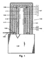
- FIG. 1 shows a cutaway lateral view of an embodiment of an apparatus for contacting high temperature gases of this invention.
- the reactor 100 comprises a pressurizable shell 101.
- the pressurizable shell 101 may comprise a stainless steel.
- the inner surface of pressurizable shell 101 is thermally insulated from heating element 106 by thermal insulator 102.
- Thermal insulator 102 comprises insulation layer 103 and heat shield 105.
- Thermal insulator 102 may be the same as or similar to the design described in U.S. Patent 5,126,112 and shown in Figure 2 , described herein.
- Thermal insulator 102 may be formed from standard high temperature insulating materials, for example, flexible or rigid carbon or graphite felt and solid sheets of flexible graphite.
- thermal insulator 102 may comprise a SiC-based material, as described herein.
- One or more of the insulation layer 103 and the heat shield 105 may comprise a SiC-based material.
- the reactor 100 may further comprise an outer chamber 117 between the pressurizable shell and the insulation layer 103.
- Heating element 106 may have a standard configuration, for example, one or more rods or panels positioned around the exterior of the reaction chamber 107 formed by outer cylinder 112, inner cylinder 113, diverter 114, and fasteners 115.
- heating element 106 may be a single, monolithic part.
- Heating element 106 may be formed from carbon, graphite, or a silicon carbide coated carbon composite.
- heating element 106 may be formed from a SiC-based material, such as CMC, or Ceramic SiC, exemplified by recrystallized silicon carbide, reaction bonded silicon carbide, and sintered silicon carbide.
- Heating element 106 is electrically connected to electrode 108, which provides means for connecting to an external energy source (not shown). Heating element 106 is electrically insulated from the remainder of the reactor 100 by electrical insulators 109. Electrical insulators 109 may be formed from standard high temperature and chemically resistant insulating material, for example, fused silica or silicon nitride.
- Heating element 106 surrounds the reaction chamber 107.
- the reaction chamber 107 has a dual wall design formed by two concentrically arrayed cylinders 112, 113, a diverter 114 and a fastener 115.
- Diverter 114 forms the top of the reaction chamber 107.
- Fasteners 115 fasten diverter 114 to outer cylinder 112.
- Outer cylinder 112, inner cylinder 113, diverter 114, and fasteners 115 may be formed from standard materials of construction for high temperature reactors, for example, carbon, graphite, silicon carbide coated carbon, and silicon carbide coated graphite; or from silicon carbide coated carbon fiber composites.
- outer cylinder 112, inner cylinder 113, diverter 114, and fasteners 115 may comprise a SiC-based material, such as Ceramic SiC or CVD SiC, alternatively Ceramic SiC.
- Fasteners 115 may comprise Ceramic SiC or CMC, alternatively Ceramic SiC. Suitable fasteners 115 may be threaded screws, or equivalents thereof available to one skilled in the art without undue experimentation.
- the reactor 100 is mounted to heat exchanger 116, where the gases (e . g ., hydrogen and tetrachlorosilane) fed to the reactor 100 are preheated before entering the gas flow path 110. These gases then flow through the gas flow path 110 of the reaction chamber 107, where additional heating occurs from heating element 106. The gases are diverted by diverter 114 to direct flow through the reaction zone 111. Heated gases exiting then pass through heat exchanger 116, transferring heat to the incoming feed gases.
- Heat exchanger 116 may be of standard design, for example, heat exchanger 116 may be the same as or similar to those heat exchangers disclosed in U.S. Patents 2,821,369 ; 3,250,322 ; and 3,391,016 .
- heat exchanger 116 may comprise a SiC-based material, such as CMC, Ceramic SiC, CVD SiC, or a SiC-based material in combination with ( e . g ., coated with) another SiC-based material such as Ceramic SiC coated with CVD SiC.
- SiC-based material such as CMC, Ceramic SiC, CVD SiC
- SiC-based material in combination with ( e . g ., coated with) another SiC-based material such as Ceramic SiC coated with CVD SiC.
- outer cylinder 112, diverter 114, and fastener 115 may be formed from one monolithic piece of Ceramic SiC or combinations of Ceramic SiC with another SiC-based material, such as CVD SiC.
- outer cylinder 112 and inner cylinder 113 may each be formed from more than one piece of a SiC-based material.
- Heat exchanger 116 may be formed from one monolithic piece of a SiC-based material, or heat exchanger 116 may be formed from more than one piece of a SiC-based material.
- Heating element 106 may be formed from one monolithic piece of Ceramic SiC.
- the reaction chamber 107 may have a single wall design. Furthermore, combinations of SiC-based materials may be used, for example one SiC-based material, such as Ceramic SiC, coated with another SiC-based material, such as CVD SiC, may be used to fabricate parts of the apparatus.
- SiC-based materials for example one SiC-based material, such as Ceramic SiC, coated with another SiC-based material, such as CVD SiC, may be used to fabricate parts of the apparatus.
- This invention further relates to a thermal insulator that may be used in the reactor described above.
- the thermal insulator comprises:
- the insulation layer may consist of a SiC-based material of construction.
- the insulation layer may comprise SiC Insulation.
- at least one of the heat shield and the insulation layer consists of a SiC-based material of construction.
- the heat shield may comprise:
- the heat shield may consists of a SiC-based material such as CMC or Ceramic SiC.
- the heat shield may be formed as one monolithic piece of a SiC-based material such as CMC or Ceramic SiC, or combinations thereof.
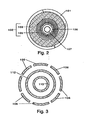
- FIG. 2 is a cross-sectional view of a reactor including a thermal insulator of this invention.
- the reactor comprises a pressurizable shell 101, as described for figure 1 .
- the inner surface of pressurizable shell 101 is thermally insulated from heating element 106 by thermal insulator 102.
- Heating element 106 may have a standard configuration, for example, one or more rods or panels positioned around the exterior of the reaction zone 107.
- Heating element 106 may be formed from carbon, graphite, or a silicon carbide coated carbon composite.
- heating element 106 may be formed from a SiC-based material, such as CMC or Ceramic SiC.
- Thermal insulator 102 comprises a heat shield 105 and insulation layer 103.
- Insulation layer 103 may comprise carbon-based rigid felt, as disclosed in U.S. Patent 5,126,112 .
- insulation layer 103 may consists of a SiC-based material such as SiC Insulation.
- the heat shield 105 comprises a continuous sheet wound in a spiral around the heating element 106.
- the heat shield 105 may further comprise spacers (not shown) between wraps.
- the heat shield 105 may consists of a SiC-based material such as CMC or Ceramic SiC.
- the heat shield 105 may be formed as one monolithic piece of a SiC-based material such as CMC or Ceramic SiC, or combinations thereof.
- the thermal insulator 102 may alternatively be formed as a single, monolithic SiC-based part.
- One skilled in the art would be able to select a suitable thermal insulator design and suitable SiC-based materials of construction for one or more parts of the thermal insulator design based on the disclosure herein.
- Heating element 106 may have any design available to one of ordinary skill in the art without undue experimentation, such as the picket fence design shown in Figure 3.
- Figure 3 shows a heating element 106 in the reactor of figure 1 .
- Heating element 106 surrounds an outer cylinder 112.
- the outer cylinder 112 surrounds an inner cylinder 113.
- Heating element 106 may comprise one or more rods or panels positioned around the outer cylinder 112.
- Heating element 106 may comprise carbon, graphite, or a silicon carbide coated carbon composite.
- heating element 106 may consists of a SiC-based material of construction, such as CMC or Ceramic SiC, or a combination thereof.
- the heating element may be formed of one monolithic piece of SiC-based material, such as Ceramic SiC, rather than rods or panels.
- heating element 106 may consist of CMC.
- heating element designs described above are exemplary and not limiting.
- One skilled in the art would be able to select a suitable heating element design and suitable SiC-based materials of construction for one or more parts of the heating element design based on the disclosure herein.
- This invention relates to a method of using the apparatus described above to prepare a product comprising trichlorosilane.
- the method comprises passing a gas mixture comprising hydrogen and tetrachlorosilane through the apparatus described above.
- the method may further comprise preheating the gas mixture in a heat exchanger prior to passing the gas mixture through the apparatus.
- a Ceramic SiC part that is coated with a CVD SiC coating is installed in a reactor for the hydrogenation of tetrachlorosilane at Hemlock Semiconductor Corporation. After normal operation for 1000 hours, the part is removed. No changes in the base material or coating are visually observable before and after installation.
- the same part design as used in example 1 is fabricated from graphite and coated by chemical vapor deposition of SiC. This part is installed in reactor for the hydrogenation of tetrachlorosilane at Hemlock Semiconductor Corporation. After normal operation for 1000 hours, this part is removed. Degradation and corrosion are visible.
Landscapes
- Chemical & Material Sciences (AREA)
- Organic Chemistry (AREA)
- Chemical Kinetics & Catalysis (AREA)
- Silicon Compounds (AREA)
- Physical Or Chemical Processes And Apparatus (AREA)
- Chemical Vapour Deposition (AREA)
Description
- This invention relates to making use of an improved apparatus for contacting gases at high temperature for hydrogenation of tetrachlorosilane.
- In a process for preparing semiconductor-grade silicon, silicon may be deposited on a heated element by reducing trichlorosilane gas in the presence of hydrogen. However, this process may suffer from the drawback that a significant portion of the trichlorosilane gas is de-hydrogenated to form by-product tetrachlorosilane. It is desirable to convert this by-product tetrachlorosilane back into trichlorosilane, which may be recycled to the deposition process.
- Various processes for hydrogenation of tetrachlorosilane (converting tetrachlorosilane to trichlorosilane) are known in the art. For example, tetrachlorosilane may be reacted with hydrogen at a temperature of 600 to 1200 °C in an equilibration reaction. Trichlorosilane, other by-product chlorosilanes, and HCl may be formed. Reactors for the hydrogenation of tetrachlorosilane should be able to withstand the high temperatures and corrosive nature of the materials such as chlorosilanes and HCl in the process. Suitable reactors for converting tetrachlorosilane to trichlorosilane may comprise a pressurizable shell, a thermal insulator surrounded by the pressurizable shell, a heating element surrounded by the thermal insulator, and a reaction chamber surrounded by the heating element for reacting the hydrogen gas with the tetrachlorosilane.
- In such reactors, it is often not possible to entirely confine the hydrogen and tetrachlorosilane fed to the reaction chamber. These gases may leak through seals and joints in the reactor into surrounding spaces containing insulation and other structural elements. When hydrogen gas contacts these structural elements, a number of detrimental reactions are possible, depending on the composition of the structural element and temperature at the contact location. For example, at temperatures of 400 to 1000 °C, hydrogen may react with carbon and carbon-based materials of construction, such as heating elements and thermal insulators, to form methane. The methane may cause contamination in the trichlorosilane product. At temperatures above 800 °C, in the presence of hydrogen and chlorosilanes, carbon and carbon-based materials may convert to silicon carbide with the liberation of HCl. This reaction may degrade the physical integrity of the carbon and carbon-based elements. Furthermore, silicon may be deposited on high temperature parts in the reactor. In an atmosphere containing hydrogen and tetrachlorosilane where the concentration of hydrogen is greater than 85 mole %, the tetrachlorosilane may be reduced to elemental silicon and deposited on high-temperature parts of the reactor. A buildup of silicon in the reactor may inhibit heat transfer within the reactor as well as make parts of the reactor brittle and difficult to disassemble. Also, hydrogen gas has a high thermal conductivity and its presence in the space between the reaction chamber and the pressurizable shell may cause increased heat loss from the reactor and increased shell temperature in comparison to gases with lower thermal conductivity.
- In existing reactors for converting tetrachlorosilane to trichlorosilane, carbon and carbon based materials, such as graphite, are used as materials of construction. For example, rigid graphite felt in combination with a flexible graphite platform may be used as thermal insulators in reactors for hydrogenation of chlorosilanes. Rigid graphite felt is a porous carbon fiber carbon bonded material with insulating properties. However, rigid graphite felt may be susceptible to attack by high temperature hydrogen, which produces carbon compounds. These carbon compounds may contaminate silicon produced by the deposition process, as described above.
- Heating elements have been prepared using a carbon fiber composite (CFCC) coated with silicon carbide. CFCC may consist of layers of carbon fibers that are cured to from a plastic like "green" body and then infiltrated with a carbon containing liquid or gas to form a carbon matrix. The material may then be further processed to graphitize the carbon. The resulting material may be coated with silicon carbide using a chemical vapor deposition process. The resulting coated material is the composite. A full cylindrical unit may be formed as a single, monolithic part or constructed from multiple parts connected together with fasteners such as screws. Failure may be caused by chemical reaction of the carbon matrix, fibers, or both, with chlorosilanes or hydrogen. Cylinders comprising graphite blocks coated with a thin layer of silicon carbide by a chemical vapor deposition process have also been used.
- Carbon and carbon based materials of construction, which are coated with silicon carbide may suffer from the drawback that it is difficult to achieve a uniform coating of silicon carbide over some surfaces of different parts. Furthermore, over time, chlorosilane gas, hydrogen gas, or both may penetrate the silicon carbide coating through cracks or through areas of thinner coating and cause degradation of the carbon and carbon based materials underneath. As this occurs, increasing amounts of carbon compounds that contaminate silicon are produced, and ultimately, the part may fail. Therefore, there is a continuing need to design process equipment with longer life.
-
US 5,422,088 andUS 5,906,799 describe processes and reactors for contacting hydrogen gas and tetrachlorosilane. Certain components of the reactor may be formed from silicon carbide coated carbon, silicon carbide coated graphite or silicon carbide coated carbon fiber composites. -
EP 0 579 942 describes reformer tubes for use in reformer reactors including ceramic tubes. Preferably the ceramic tube is made from alpha silicon carbide. - This invention relates to an apparatus suitable for use in contacting high temperature gases, such as tetrachlorosilane and hydrogen. At least one part of the apparatus that contacts a high temperature gas consists of a silicon carbide based material of construction.
- All amounts, ratios, and percentages are by weight unless otherwise indicated. The following is a list of definitions, as used herein.
- "CMC" means a ceramic matrix composite comprising a silicon carbide matrix reinforced with carbon fibers or silicon carbide fibers, or a combination thereof. CMC may optionally be infiltrated with silicon or silicon carbide. CMC may be produced, for example, as described in
U.S. Patents 4,294,788 and5,738,908 . - "Ceramic SiC" means a silicon carbide produced by a process comprising processing powdered silicon carbide at high temperature. Ceramic SiC may optionally be further processed by densifying or coating, or a combination thereof. Ceramic SiC may be densified by infiltration with molten or vaporized silicon, for example by the process described in
EP 0 532 985 . Ceramic SiC may be coated by a chemical vapor deposition process. Ceramic SiC includes, but is not limited to, hot pressed silicon carbide, reaction bonded silicon carbide, recrystallized silicon carbide, and sintered silicon carbide. Hot pressed silicon carbide may be produced, for example, by compacting powdered silicon carbide using heat and pressure. Hot pressed silicon carbide may be produced, for example, as described inU.S. Patents 4,108,929 and5,354,536 . Reaction bonded silicon carbide may be produced, for example, by processing powdered silicon carbide with carbon and molten silicon. Reaction bonded silicon carbide may be produced, for example, as described inU.S. Patent 3,495,939 andEP 0 532 985 . Recrystallized silicon carbide may be produced, for example, as described inU.S. Patents 5,840,639 and5,925,310 . Sintered silicon carbide may be produced, for example, by processing powdered silicon carbide with a sintering agent and a binder or resin. Sintered silicon carbide may be produced, for example, as described inU.S. Patents 5,082,597 and5,656,218 . - "CVD SiC" means a silicon carbide produced by a process comprising chemical vapor deposition of silicon carbide on a mandrel, such as graphite, and thereafter removing the mandrel. CVD SiC may be produced, for example, as described in
U.S. Patents 5,374,412 and5,604,151 . - "SiC Insulation" means a silicon carbide produced by a process comprising infiltrating a fibrous or porous, carbon or carbon based, material of construction with a silicon-containing source gas to provide individual fibers or pores with a coating of silicon carbide, or to convert individual fibers to silicon carbide, or combinations thereof; thereby yielding a silicon carbide, which as compared to CMC is relatively thermally insulating. SiC Insulation may be produced, for example, as described in
U.S. Patent 4,481,179 . - "SiC-based" means silicon carbide-based and includes but is not limited to CMC, Ceramic SiC, CVD SiC, and SiC Insulation.
- Although in the past carbon-based parts and carbon-based parts coated with silicon carbide have been used in reactors suitable for contacting high temperature gases, such as reactors for hydrogenating tetrachlorosilane, SiC-based parts suitable for use in such reactors have not been available until now due to difficulties in the manufacture of SiC-based parts of sufficient size and complex geometry. The inventors surprisingly found benefits by replacing carbon and carbon-based reactor parts, even such parts coated with silicon carbide, with SiC-based parts in a reactor used for hydrogenating tetrachlorosilane. The benefits include that such replacement may reduce the amounts of carbon containing impurities in the trichlorosilane product upon initial installation of the SiC-based part, as compared to carbon-based parts and carbon-based parts coated with silicon carbide. Such replacement may also reduce the amounts of carbon containing impurities in the trichlorosilane product over time, as compared to carbon-based parts and carbon-based parts coated with silicon carbide. Further benefits include that useable lifetimes of SiC-based parts may increase as compared to carbon-based parts and carbon-based parts coated with silicon carbide.
- This invention relates to a method which uses an apparatus that is suitable for contacting high temperature gases, e.g., hydrogen and tetrachlorosilane, where at least one part in the apparatus, which contacts a high temperature gas, consists of a material of construction selected from SiC and CVD SiC. Suitable designs are known in the art. For example, the portions of
U.S. Patents 4,536,642 ;5,126,112 ;5,422,088 ; and5,906,799 disclosing designs of reactors suitable for contacting high temperature gases, and parts for use in said reactors. - A method for producing a product comprising trichlorosilane which comprises:
- passing a gas mixture comprising hydrogen and tetrachlorosilane through an apparatus which comprises:
- a reactor (100) comprising
- i) a pressurizable shell (101),
- ii) a thermal insulator (102) surrounded by the pressurizable shell (101),
- iii) a heating element (106) surrounded by the thermal insulator (102), and
- iv) a reaction chamber (107) surrounded by the heating element (106), wherein the reaction chamber (107) comprises
- a) a diverter (114) forming the top of the reaction chamber (107),
- b) an outer cylinder (112) surrounded by the heating element (106), and
- c) an inner cylinder (113) surrounded by the outer cylinder (112), and
- d) a fastener (115) connecting the diverter (114) to the outer cylinder (112);
- a reactor (100) comprising
- forming a gas flow path between the outer cylinder (112) and the inner cylinder (113);
- reacting the gas mixture at a high temperature in a reaction zone formed in the center of the inner cylinder (113); and where at least one of the outer cylinder (112), the inner cylinder (113), the diverter (114), and the fastener (115) consists of a material of construction selected from Ceramic SiC and CVD SiC.
- The reactor may further comprise an outer chamber between the pressurizable shell and the thermal insulator. The reactor may be mounted to a heat exchanger. The heat exchanger may be the same as or similar to those heat exchangers disclosed in
U.S. Patents 2,821,369 ;3,250,322 ; and3,391,016 . The portions ofU.S. Patents 2,821,369 ;3,250,322 ; and3,391,016 disclosing designs of heat exchangers and parts for use in these heat exchangers are hereby incorporated by reference. Alternatively, the heat exchanger, or a part thereof, may comprise a SiC-based material of construction, such as CMC or Ceramic SiC, or combinations thereof. -
Figure 1 shows a cutaway lateral view of an embodiment of an apparatus for contacting high temperature gases of this invention. Thereactor 100 comprises apressurizable shell 101. Thepressurizable shell 101 may comprise a stainless steel. The inner surface ofpressurizable shell 101 is thermally insulated fromheating element 106 bythermal insulator 102.Thermal insulator 102 comprisesinsulation layer 103 andheat shield 105.Thermal insulator 102 may be the same as or similar to the design described inU.S. Patent 5,126,112 and shown inFigure 2 , described herein.Thermal insulator 102 may be formed from standard high temperature insulating materials, for example, flexible or rigid carbon or graphite felt and solid sheets of flexible graphite. Alternatively,thermal insulator 102 may comprise a SiC-based material, as described herein. One or more of theinsulation layer 103 and theheat shield 105 may comprise a SiC-based material. Thereactor 100 may further comprise anouter chamber 117 between the pressurizable shell and theinsulation layer 103. -
Heating element 106 may have a standard configuration, for example, one or more rods or panels positioned around the exterior of thereaction chamber 107 formed byouter cylinder 112,inner cylinder 113,diverter 114, andfasteners 115. Alternatively,heating element 106 may be a single, monolithic part.Heating element 106 may be formed from carbon, graphite, or a silicon carbide coated carbon composite. Alternatively,heating element 106 may be formed from a SiC-based material, such as CMC, or Ceramic SiC, exemplified by recrystallized silicon carbide, reaction bonded silicon carbide, and sintered silicon carbide. -
Heating element 106 is electrically connected toelectrode 108, which provides means for connecting to an external energy source (not shown).Heating element 106 is electrically insulated from the remainder of thereactor 100 byelectrical insulators 109.Electrical insulators 109 may be formed from standard high temperature and chemically resistant insulating material, for example, fused silica or silicon nitride. -
Heating element 106 surrounds thereaction chamber 107. Infigure 1 , thereaction chamber 107 has a dual wall design formed by two concentrically arrayedcylinders diverter 114 and afastener 115.Diverter 114 forms the top of thereaction chamber 107.Fasteners 115 fasten diverter 114 toouter cylinder 112.Outer cylinder 112,inner cylinder 113,diverter 114, andfasteners 115 may be formed from standard materials of construction for high temperature reactors, for example, carbon, graphite, silicon carbide coated carbon, and silicon carbide coated graphite; or from silicon carbide coated carbon fiber composites. Alternatively, one or more ofouter cylinder 112,inner cylinder 113,diverter 114, andfasteners 115 may comprise a SiC-based material, such as Ceramic SiC or CVD SiC, alternatively Ceramic SiC.Fasteners 115 may comprise Ceramic SiC or CMC, alternatively Ceramic SiC.Suitable fasteners 115 may be threaded screws, or equivalents thereof available to one skilled in the art without undue experimentation. - The
reactor 100 is mounted toheat exchanger 116, where the gases (e.g., hydrogen and tetrachlorosilane) fed to thereactor 100 are preheated before entering thegas flow path 110. These gases then flow through thegas flow path 110 of thereaction chamber 107, where additional heating occurs fromheating element 106. The gases are diverted bydiverter 114 to direct flow through thereaction zone 111. Heated gases exiting then pass throughheat exchanger 116, transferring heat to the incoming feed gases.Heat exchanger 116 may be of standard design, for example,heat exchanger 116 may be the same as or similar to those heat exchangers disclosed inU.S. Patents 2,821,369 ;3,250,322 ; and3,391,016 . Alternatively,heat exchanger 116 may comprise a SiC-based material, such as CMC, Ceramic SiC, CVD SiC, or a SiC-based material in combination with (e.g., coated with) another SiC-based material such as Ceramic SiC coated with CVD SiC. - One skilled in the art would be able to select a suitable design and suitable SiC-based materials of construction for one or more parts of the apparatus based on the disclosure herein. For example,
outer cylinder 112,diverter 114, andfastener 115 may be formed from one monolithic piece of Ceramic SiC or combinations of Ceramic SiC with another SiC-based material, such as CVD SiC. Alternativelyouter cylinder 112 andinner cylinder 113 may each be formed from more than one piece of a SiC-based material.Heat exchanger 116 may be formed from one monolithic piece of a SiC-based material, orheat exchanger 116 may be formed from more than one piece of a SiC-based material.Heating element 106 may be formed from one monolithic piece of Ceramic SiC. Thereaction chamber 107 may have a single wall design. Furthermore, combinations of SiC-based materials may be used, for example one SiC-based material, such as Ceramic SiC, coated with another SiC-based material, such as CVD SiC, may be used to fabricate parts of the apparatus. - This invention further relates to a thermal insulator that may be used in the reactor described above. The thermal insulator comprises:
- a) an insulation layer, and
optionally b) a heat shield surrounded by the insulation layer, when present. - The insulation layer may consist of a SiC-based material of construction. The insulation layer may comprise SiC Insulation. When the heat shield is present, at least one of the heat shield and the insulation layer consists of a SiC-based material of construction.
- The heat shield may comprise:
- i) a sheet wrapped in a spiral, and
- optionally ii) spacers between wraps of the sheet.
- Alternatively, the heat shield may consists of a SiC-based material such as CMC or Ceramic SiC. Alternatively, the heat shield may be formed as one monolithic piece of a SiC-based material such as CMC or Ceramic SiC, or combinations thereof.
-
Figure 2 is a cross-sectional view of a reactor including a thermal insulator of this invention. The reactor comprises apressurizable shell 101, as described forfigure 1 . The inner surface ofpressurizable shell 101 is thermally insulated fromheating element 106 bythermal insulator 102.Heating element 106 may have a standard configuration, for example, one or more rods or panels positioned around the exterior of thereaction zone 107.Heating element 106 may be formed from carbon, graphite, or a silicon carbide coated carbon composite. Alternatively,heating element 106 may be formed from a SiC-based material, such as CMC or Ceramic SiC. -
Thermal insulator 102 comprises aheat shield 105 andinsulation layer 103.Insulation layer 103 may comprise carbon-based rigid felt, as disclosed inU.S. Patent 5,126,112 . Alternatively,insulation layer 103 may consists of a SiC-based material such as SiC Insulation. - The
heat shield 105 comprises a continuous sheet wound in a spiral around theheating element 106. Theheat shield 105 may further comprise spacers (not shown) between wraps. Alternatively, theheat shield 105 may consists of a SiC-based material such as CMC or Ceramic SiC. Alternatively, theheat shield 105 may be formed as one monolithic piece of a SiC-based material such as CMC or Ceramic SiC, or combinations thereof. - The
thermal insulator 102 may alternatively be formed as a single, monolithic SiC-based part. One skilled in the art would be able to select a suitable thermal insulator design and suitable SiC-based materials of construction for one or more parts of the thermal insulator design based on the disclosure herein. - This invention further relates to a heating element that may be used in the reactor described above. The heating element may have any design available to one of ordinary skill in the art without undue experimentation, such as the picket fence design shown in
Figure 3. Figure 3 shows aheating element 106 in the reactor offigure 1 .Heating element 106 surrounds anouter cylinder 112. Theouter cylinder 112 surrounds aninner cylinder 113.Heating element 106 may comprise one or more rods or panels positioned around theouter cylinder 112.Heating element 106 may comprise carbon, graphite, or a silicon carbide coated carbon composite. Alternatively,heating element 106 may consists of a SiC-based material of construction, such as CMC or Ceramic SiC, or a combination thereof. Alternatively, the heating element may be formed of one monolithic piece of SiC-based material, such as Ceramic SiC, rather than rods or panels. Alternatively,heating element 106 may consist of CMC. - One skilled in the art would recognize that the heating element designs described above are exemplary and not limiting. One skilled in the art would be able to select a suitable heating element design and suitable SiC-based materials of construction for one or more parts of the heating element design based on the disclosure herein.
- This invention relates to a method of using the apparatus described above to prepare a product comprising trichlorosilane. The method comprises passing a gas mixture comprising hydrogen and tetrachlorosilane through the apparatus described above. The method may further comprise preheating the gas mixture in a heat exchanger prior to passing the gas mixture through the apparatus.
- These examples further illustrate the invention.
- A Ceramic SiC part that is coated with a CVD SiC coating is installed in a reactor for the hydrogenation of tetrachlorosilane at Hemlock Semiconductor Corporation. After normal operation for 1000 hours, the part is removed. No changes in the base material or coating are visually observable before and after installation.
- The same part design as used in example 1 is fabricated from graphite and coated by chemical vapor deposition of SiC. This part is installed in reactor for the hydrogenation of tetrachlorosilane at Hemlock Semiconductor Corporation. After normal operation for 1000 hours, this part is removed. Degradation and corrosion are visible.
-
-
Figure 1 is a cutaway lateral view of an apparatus of this invention. -
Figure 2 is a partial cross-sectional view of a reactor including insulation of this invention. -
Figure 3 is a partial cross-sectional view of a reactor including a heating element of this invention. -
- 100
- reactor
- 101
- pressurizable shell
- 102
- thermal insulator
- 103
- insulation layer
- 105
- heat shield
- 106
- heating element
- 107
- reaction chamber
- 108
- electrode
- 109
- electrical insulators
- 110
- gas flow path
- 111
- reaction zone
- 112
- outer cylinder
- 113
- inner cylinder
- 114
- diverter
- 115
- fasteners
- 116
- heat exchanger
- 117
- outer chamber
Claims (16)
- A method for producing a product comprising trichlorosilane which comprises:passing a gas mixture comprising hydrogen and tetrachlorosilane through an apparatus which comprises:a reactor (100) comprisingi) a pressurizable shell (101),ii) a thermal insulator (102) surrounded by the pressurizable shell (101),iii) a heating element (106) surrounded by the thermal insulator (102), andiv) a reaction chamber (107) surrounded by the heating element (106), wherein the reaction chamber (107) comprisesa) a diverter (114) forming the top of the reaction chamber (107),b) an outer cylinder (112) surrounded by the heating element (106), andc) an inner cylinder (113) surrounded by the outer cylinder (112), andd) a fastener (115) connecting the diverter (114) to the outer cylinder (112);forming a gas flow path between the outer cylinder (112) and the inner cylinder (113);reacting the gas mixture at a high temperature in a reaction zone formed in the center of the inner cylinder (113); and where at least one of the outer cylinder (112), the inner cylinder (113), the diverter (114), and the fastener (115) consists of a material of construction selected from Ceramic SiC and CVD SiC.
- The method of claim 1, where the reactor (100) further comprises an outer chamber (117) between the pressurizable shell (101) and the thermal insulator (102).
- The method of claim 1, wherein the apparatus further comprises a heat exchanger (116), where the reactor (100) is mounted to the heat exchanger (116).
- The method of claim 1, wherein the apparatus further comprises a heat exchanger (116) comprising a silicon carbide-based material of construction, where the reactor is mounted to the heat exchanger (116).
- The method of claim 1, wherein the apparatus further comprisies a heat exchanger (116), where the heat exchanger consists of CMC, Ceramic SiC, CVD SiC, or an SiC-based material coated with SiC Insulation, and where the reactor (100) is mounted to the heat exchanger (116).
- The method of claim 1, where the thermal insulator (102) comprises:a) an insulation layer (103), andoptionally b) a heat shield (105) surrounded by the insulation layer, when present.
- The method of claim 1, where the insulation layer (103) comprises SiC Insulation.
- The method of claim 1, where the heat shield (105) is present and the heat shield (105) comprises:i) a sheet wrapped in a spiral, andoptionally ii) spacers between wraps of the sheet.
- The method of claim 1, where the heat shield (105) is present and the heat shield (105) consists of CMC or Ceramic SiC, or a combination thereof.
- The method of claim 1, where the diverter (114) consists of Ceramic SiC.
- The method of claim 1, where the outer cylinder (112) consists of Ceramic SiC.
- The method of claim 1, where the inner cylinder (113) consists of Ceramic SiC.
- A method of claim 1, where the heating element consists of Ceramic SiC.
- The method of claim 13, where the heating element has a picket fence design.
- The method of claim 13, where the heating element is formed from one monolithic piece of the Ceramic SiC.
- The method of any one of claims 1 to 15, further comprising preheating the gas mixture in a heat exchanger prior to passing the gas mixture through the apparatus.
Applications Claiming Priority (2)
| Application Number | Priority Date | Filing Date | Title |
|---|---|---|---|
| US378360 | 2003-03-03 | ||
| US10/378,360 US20040173597A1 (en) | 2003-03-03 | 2003-03-03 | Apparatus for contacting gases at high temperature |
Publications (2)
| Publication Number | Publication Date |
|---|---|
| EP1454670A1 EP1454670A1 (en) | 2004-09-08 |
| EP1454670B1 true EP1454670B1 (en) | 2008-05-14 |
Family
ID=32824754
Family Applications (1)
| Application Number | Title | Priority Date | Filing Date |
|---|---|---|---|
| EP04250061A Expired - Lifetime EP1454670B1 (en) | 2003-03-03 | 2004-01-08 | Trichlorosilane production in apparatus comprising SiC parts |
Country Status (4)
| Country | Link |
|---|---|
| US (1) | US20040173597A1 (en) |
| EP (1) | EP1454670B1 (en) |
| JP (2) | JP5153992B2 (en) |
| DE (1) | DE602004013656D1 (en) |
Cited By (3)
| Publication number | Priority date | Publication date | Assignee | Title |
|---|---|---|---|---|
| DE102014205001A1 (en) | 2014-03-18 | 2015-09-24 | Wacker Chemie Ag | Process for the preparation of trichlorosilane |
| US9217609B2 (en) | 2011-06-21 | 2015-12-22 | Gtat Corporation | Apparatus and methods for conversion of silicon tetrachloride to trichlorosilane |
| US10315181B2 (en) | 2010-09-27 | 2019-06-11 | Gtat Corporation | Heater and related methods therefor |
Families Citing this family (26)
| Publication number | Priority date | Publication date | Assignee | Title |
|---|---|---|---|---|
| DE102005046703A1 (en) | 2005-09-29 | 2007-04-05 | Wacker Chemie Ag | Hydrogenation of chlorosilane comprises contacting silicon-containing compound and hydrogen with surface of reaction chamber and surface of heater such that silicon carbide coating is formed in situ on the surfaces in first process step |
| JP5205910B2 (en) * | 2006-10-31 | 2013-06-05 | 三菱マテリアル株式会社 | Trichlorosilane production equipment |
| JP5428145B2 (en) * | 2006-10-31 | 2014-02-26 | 三菱マテリアル株式会社 | Trichlorosilane production equipment |
| JP5205906B2 (en) * | 2006-10-31 | 2013-06-05 | 三菱マテリアル株式会社 | Trichlorosilane production equipment |
| JP2008150277A (en) * | 2006-11-21 | 2008-07-03 | Mitsubishi Materials Corp | Heat and corrosion resistant member and trichlorosilane production equipment |
| JP5012449B2 (en) * | 2006-11-28 | 2012-08-29 | 三菱マテリアル株式会社 | Trichlorosilane production equipment |
| KR101235228B1 (en) * | 2008-08-08 | 2013-02-20 | 니혼 하츠쵸 가부시키가이샤 | Work member, electric contact member, contact probe, and manufacturing method of electric contact member |
| KR101117290B1 (en) * | 2009-04-20 | 2012-03-20 | 에이디알엠테크놀로지 주식회사 | Reactor for the production of trichlorosilane |
| DE102010000979A1 (en) * | 2010-01-18 | 2011-07-21 | Evonik Degussa GmbH, 45128 | Use of a pressure operated ceramic heat exchanger as an integral part of a plant for converting silicon tetrachloride to trichlorosilane |
| DE102010000978A1 (en) * | 2010-01-18 | 2011-07-21 | Evonik Degussa GmbH, 45128 | Flow tube reactor for the conversion of silicon tetrachloride to trichlorosilane |
| DE102010000980A1 (en) * | 2010-01-18 | 2011-07-21 | Evonik Degussa GmbH, 45128 | Catalytic systems for the continuous conversion of silicon tetrachloride to trichlorosilane |
| JP5633375B2 (en) * | 2010-01-27 | 2014-12-03 | 三菱マテリアル株式会社 | Trichlorosilane production equipment |
| JP5482687B2 (en) | 2010-02-17 | 2014-05-07 | 三菱マテリアル株式会社 | Trichlorosilane production apparatus and production method |
| JP5637013B2 (en) * | 2010-03-04 | 2014-12-10 | 三菱マテリアル株式会社 | Trichlorosilane production apparatus and production method |
| CN102190304B (en) * | 2010-03-08 | 2015-04-15 | 三菱综合材料株式会社 | Apparatus for producing trichlorosilane |
| CN102190305B (en) * | 2010-03-15 | 2014-10-29 | 三菱综合材料株式会社 | Apparatus for producing trichlorosilane |
| DE102010039267A1 (en) * | 2010-08-12 | 2012-02-16 | Evonik Degussa Gmbh | Use of a reactor with integrated heat exchanger in a process for the hydrodechlorination of silicon tetrachloride |
| DE102011002749A1 (en) * | 2011-01-17 | 2012-07-19 | Wacker Chemie Ag | Method and apparatus for converting silicon tetrachloride to trichlorosilane |
| EP2688839B1 (en) * | 2011-03-25 | 2016-09-14 | Evonik Degussa GmbH | Use of silicon carbide tubes with a flanged or flared end |
| US9687876B2 (en) | 2012-01-30 | 2017-06-27 | Hemlock Semiconductor Corporation | Method of repairing and/or protecting a surface in a reactor |
| DE102012223784A1 (en) * | 2012-12-19 | 2014-06-26 | Wacker Chemie Ag | Process for converting silicon tetrachloride to trichlorosilane |
| WO2016201221A1 (en) | 2015-06-10 | 2016-12-15 | Corning Incorporated | Thermal cross-talk resistant flow reactor |
| US10266414B2 (en) * | 2015-06-16 | 2019-04-23 | Hemlock Semiconductor Operations Llc | Susceptor arrangement for a reactor and method of heating a process gas for a reactor |
| EP3121149A1 (en) * | 2015-07-21 | 2017-01-25 | Evonik Degussa GmbH | Intensification of heat exchange through appropriate shaping in reversing pipe from xsic material system |
| US10710111B2 (en) | 2017-09-25 | 2020-07-14 | Raytheon Technologies Corporation | Continuous tow fiber coating reactor |
| CN109678515A (en) * | 2019-01-31 | 2019-04-26 | 邱洪 | Silicon carbide ceramics continuous flow reactor/condenser and its manufacturing method |
Family Cites Families (42)
| Publication number | Priority date | Publication date | Assignee | Title |
|---|---|---|---|---|
| GB756327A (en) * | 1952-10-14 | 1956-09-05 | Lorraine Carbone | Improvements in or relating to heat exchangers |
| US3250322A (en) * | 1964-02-07 | 1966-05-10 | Texas Instruments Inc | Corrosive fluid heat exchanger |
| US3391016A (en) * | 1964-02-07 | 1968-07-02 | Texas Instruments Inc | Silicon carbide coating on graphite bores of heat exchanger |
| GB1180918A (en) * | 1966-06-10 | 1970-02-11 | Atomic Energy Authority Uk | Improvements in or relating to the Manufacture of Dense Bodies of Silicon Carbide. |
| US4108929A (en) * | 1974-09-03 | 1978-08-22 | General Electric Company | Hot pressed silicon carbide |
| US4341725A (en) * | 1977-12-13 | 1982-07-27 | Weaver Gerald Q | Molding refractory and metal shapes by slip-casting |
| US4294788A (en) * | 1979-12-05 | 1981-10-13 | General Electric Company | Method of making a shaped silicon carbide-silicon matrix composite and articles made thereby |
| DE3024320A1 (en) * | 1980-06-27 | 1982-04-01 | Wacker-Chemitronic Gesellschaft für Elektronik-Grundstoffe mbH, 8263 Burghausen | DEVICE FOR HIGH TEMPERATURE TREATMENT OF GASES |
| US4481179A (en) * | 1983-10-12 | 1984-11-06 | The United States Of America As Represented By The United States Department Of Energy | Method for forming fibrous silicon carbide insulating material |
| DK167426B1 (en) * | 1985-10-17 | 1993-11-01 | Inst Francais Du Petrole | PROCEDURE FOR OXYDATION OF AN OXIDIZABLE CHARGE IN GAS PHASE WITH A GAS MIXTURE AND REACTOR FOR EXERCISING THE PROCEDURE |
| DE3668163D1 (en) * | 1985-11-08 | 1990-02-15 | Inst Francais Du Petrole | METHOD FOR THERMALLY CONVERTING METHANE IN HYDROCARBONS WITH HIGHER MOLECULAR WEIGHTS. |
| US4973777A (en) * | 1985-11-08 | 1990-11-27 | Institut Francais Du Petrole | Process for thermally converting methane into hydrocarbons with higher molecular weights, reactor for implementing the process and process for realizing the reactor |
| FR2592320B1 (en) * | 1985-12-30 | 1988-04-08 | Inst Francais Du Petrole | NOVEL PROCESS FOR OXIDIZING AN OXIDIZABLE CHARGE IN THE GAS PHASE AND REACTOR FOR CARRYING OUT THIS PROCESS. |
| US4963516A (en) * | 1987-07-28 | 1990-10-16 | Ngk Insulators, Ltd. | SiC complex sintered bodies and production thereof |
| JP2524816B2 (en) * | 1988-09-26 | 1996-08-14 | 東芝セラミックス株式会社 | Silicon carbide composite sintered body |
| DE4022707C2 (en) * | 1989-07-18 | 2002-01-31 | Hemlock Semiconductor Corp | Isolation system for a chlorosilane and hydrogen reactor |
| US5283089A (en) * | 1989-11-13 | 1994-02-01 | Norton Company | Non-porous diffusion furnace components |
| IT1246772B (en) * | 1989-12-26 | 1994-11-26 | Advanced Silicon Materials Inc | '' GRAPHITE SPINDLE WITH AN EXTERNAL COATING LAYER __ WATERPROOF TO HYDROGEN '' |
| JPH0681713B2 (en) * | 1990-04-05 | 1994-10-19 | 三井造船株式会社 | Insulation |
| US5589116A (en) * | 1991-07-18 | 1996-12-31 | Sumitomo Metal Industries, Ltd. | Process for preparing a silicon carbide sintered body for use in semiconductor equipment |
| US5906799A (en) * | 1992-06-01 | 1999-05-25 | Hemlock Semiconductor Corporation | Chlorosilane and hydrogen reactor |
| US5254318A (en) * | 1992-07-20 | 1993-10-19 | Stone & Webster Engineering Corporation | Lined reformer tubes for high pressure reformer reactors |
| CA2099788A1 (en) * | 1992-07-31 | 1994-02-01 | Michael A. Pickering | Ultra pure silicon carbide and high temperature semiconductor processing equipment made therefrom |
| US5374412A (en) * | 1992-07-31 | 1994-12-20 | Cvd, Inc. | Highly polishable, highly thermally conductive silicon carbide |
| TW337513B (en) * | 1992-11-23 | 1998-08-01 | Cvd Inc | Chemical vapor deposition-produced silicon carbide having improved properties and preparation process thereof |
| RU2084425C1 (en) * | 1992-12-30 | 1997-07-20 | Государственный научно-исследовательский институт конструкционных материалов на основе графита | Method of manufacturing articles from carbon-silicon carbide composite material and carbon-silicon carbide composite material |
| US5372978A (en) * | 1993-03-11 | 1994-12-13 | Cercom Inc. | Monolithic, fully dense silicon carbide material, method of manufacturing and end uses |
| FR2714076B1 (en) * | 1993-12-16 | 1996-03-15 | Europ Propulsion | Method for densifying porous substrates by chemical vapor infiltration of silicon carbide. |
| US5422088A (en) * | 1994-01-28 | 1995-06-06 | Hemlock Semiconductor Corporation | Process for hydrogenation of tetrachlorosilane |
| US5526984A (en) * | 1994-07-18 | 1996-06-18 | Saint-Gobain/Norton Industrial Ceramics Corp. | Hydrogen torch having concentric tubes and reverse ball joint connection |
| WO1996035228A1 (en) * | 1995-05-05 | 1996-11-07 | Saint-Gobain Industrial Ceramics, Inc. | Slip free vertical rack design |
| US5656218A (en) * | 1995-05-19 | 1997-08-12 | Industrial Technology Research Institute | Method for making high performance self-reinforced silicon carbide using a pressureless sintering process |
| US5719062A (en) * | 1995-06-06 | 1998-02-17 | Saint Gobain Industrial Ceramics Corporation | Process for analyzing analytes using HF-resistant ultrasonic nebulizer components |
| JP3471144B2 (en) * | 1995-09-06 | 2003-11-25 | 東京エレクトロン株式会社 | Vertical heat treatment apparatus, heat insulation structure thereof, and heat shield plate |
| JPH09268067A (en) * | 1996-03-29 | 1997-10-14 | Asahi Glass Co Ltd | Method for manufacturing silicon carbide member |
| US5702997A (en) * | 1996-10-04 | 1997-12-30 | Saint-Gobain/Norton Industrial Ceramics Corp. | Process for making crack-free silicon carbide diffusion components |
| DE19646094C2 (en) * | 1996-11-08 | 1999-03-18 | Sintec Keramik Gmbh | Process for chemical gas phase infiltration of refractory substances, in particular carbon and silicon carbide, and use of the process |
| US5770324A (en) * | 1997-03-03 | 1998-06-23 | Saint-Gobain Industrial Ceramics, Inc. | Method of using a hot pressed silicon carbide dummy wafer |
| NL1005963C2 (en) * | 1997-05-02 | 1998-11-09 | Asm Int | Vertical oven for treating semiconductor substrates. |
| DE10057481A1 (en) * | 2000-11-20 | 2002-05-23 | Solarworld Ag | Production of high-purity granular silicon comprises decomposing a silicon-containing gas in a reactor made of carbon-fiber-reinforced silicon carbide |
| JP4639005B2 (en) * | 2001-07-03 | 2011-02-23 | 株式会社トクヤマ | Method for producing silicon and trichlorosilane |
| NO316020B1 (en) * | 2001-10-10 | 2003-12-01 | Elkem Materials | Device for continuous slag treatment of silicon |
-
2003
- 2003-03-03 US US10/378,360 patent/US20040173597A1/en not_active Abandoned
-
2004
- 2004-01-08 EP EP04250061A patent/EP1454670B1/en not_active Expired - Lifetime
- 2004-01-08 DE DE602004013656T patent/DE602004013656D1/en not_active Expired - Lifetime
- 2004-03-03 JP JP2004059641A patent/JP5153992B2/en not_active Expired - Lifetime
-
2011
- 2011-03-30 JP JP2011075636A patent/JP5674527B2/en not_active Expired - Lifetime
Cited By (3)
| Publication number | Priority date | Publication date | Assignee | Title |
|---|---|---|---|---|
| US10315181B2 (en) | 2010-09-27 | 2019-06-11 | Gtat Corporation | Heater and related methods therefor |
| US9217609B2 (en) | 2011-06-21 | 2015-12-22 | Gtat Corporation | Apparatus and methods for conversion of silicon tetrachloride to trichlorosilane |
| DE102014205001A1 (en) | 2014-03-18 | 2015-09-24 | Wacker Chemie Ag | Process for the preparation of trichlorosilane |
Also Published As
| Publication number | Publication date |
|---|---|
| JP2011136904A (en) | 2011-07-14 |
| US20040173597A1 (en) | 2004-09-09 |
| JP5153992B2 (en) | 2013-02-27 |
| EP1454670A1 (en) | 2004-09-08 |
| DE602004013656D1 (en) | 2008-06-26 |
| JP2004262753A (en) | 2004-09-24 |
| JP5674527B2 (en) | 2015-02-25 |
Similar Documents
| Publication | Publication Date | Title |
|---|---|---|
| EP1454670A1 (en) | Apparatus for contacting gases at high temperature | |
| US5422088A (en) | Process for hydrogenation of tetrachlorosilane | |
| JP3781439B2 (en) | Chlorosilane and hydrogen reactor | |
| CN107683384B (en) | Airtight, thermally conductive multilayer ceramic composite pipe | |
| KR101914535B1 (en) | Fluidized bed reactor and method for producing polycrystalline silicon granules | |
| WO2011068283A1 (en) | Chemical vapor deposition reactor having a radiant heat barrier layer for improving energy efficiency | |
| EP2008969A1 (en) | Trichlorosilane production apparatus | |
| US6849244B2 (en) | Method for producing highly-pure granular silicon | |
| JP5859569B2 (en) | Method and apparatus for converting silicon tetrachloride to trichlorosilane | |
| US6114006A (en) | High thermal conductivity carbon/carbon honeycomb structure | |
| CA3133519A1 (en) | Gastight, heat permeable, ceramic and multilayered composite tube | |
| RU2407585C2 (en) | Synthesis gas production apparatus | |
| CN108138992B (en) | Isostatic graphite liners for fluidized bed reactors | |
| CN106256763B (en) | Susceptor configuration for a reactor and method of heating process gas for use in a reactor | |
| WO2010016133A1 (en) | Reactor made of carbon | |
| WO2023248097A1 (en) | Furnace configured for treatment of particulate matter in a controlled gaseous environment | |
| JP4140600B2 (en) | Manufacturing method of heat insulating material for single crystal pulling device | |
| CN213447293U (en) | Upper and lower air inlet type CVD reaction furnace | |
| WO2010016134A1 (en) | Reaction vessel made of carbon | |
| KR20130106038A (en) | Trichlorosilane conversion reactor with divided heat shield | |
| JP2005104833A (en) | Gas rectifying member for single crystal pulling apparatus |
Legal Events
| Date | Code | Title | Description |
|---|---|---|---|
| PUAI | Public reference made under article 153(3) epc to a published international application that has entered the european phase |
Free format text: ORIGINAL CODE: 0009012 |
|
| AK | Designated contracting states |
Kind code of ref document: A1 Designated state(s): AT BE BG CH CY CZ DE DK EE ES FI FR GB GR HU IE IT LI LU MC NL PT RO SE SI SK TR |
|
| AX | Request for extension of the european patent |
Extension state: AL LT LV MK |
|
| 17P | Request for examination filed |
Effective date: 20041020 |
|
| AKX | Designation fees paid |
Designated state(s): DE IT |
|
| 17Q | First examination report despatched |
Effective date: 20060714 |
|
| 17Q | First examination report despatched |
Effective date: 20060714 |
|
| 17Q | First examination report despatched |
Effective date: 20060714 |
|
| RTI1 | Title (correction) |
Free format text: TRICHLOROSILANE PRODUCTION IN APPARATUS COMPRISING SIC PARTS |
|
| GRAP | Despatch of communication of intention to grant a patent |
Free format text: ORIGINAL CODE: EPIDOSNIGR1 |
|
| GRAS | Grant fee paid |
Free format text: ORIGINAL CODE: EPIDOSNIGR3 |
|
| GRAA | (expected) grant |
Free format text: ORIGINAL CODE: 0009210 |
|
| AK | Designated contracting states |
Kind code of ref document: B1 Designated state(s): DE IT |
|
| REF | Corresponds to: |
Ref document number: 602004013656 Country of ref document: DE Date of ref document: 20080626 Kind code of ref document: P |
|
| PLBE | No opposition filed within time limit |
Free format text: ORIGINAL CODE: 0009261 |
|
| STAA | Information on the status of an ep patent application or granted ep patent |
Free format text: STATUS: NO OPPOSITION FILED WITHIN TIME LIMIT |
|
| 26N | No opposition filed |
Effective date: 20090217 |
|
| REG | Reference to a national code |
Ref country code: DE Ref legal event code: R082 Ref document number: 602004013656 Country of ref document: DE Representative=s name: FLEISCHER, ENGELS & PARTNER MBB, PATENTANWAELT, DE |
|
| PGFP | Annual fee paid to national office [announced via postgrant information from national office to epo] |
Ref country code: IT Payment date: 20180122 Year of fee payment: 15 |
|
| PG25 | Lapsed in a contracting state [announced via postgrant information from national office to epo] |
Ref country code: IT Free format text: LAPSE BECAUSE OF NON-PAYMENT OF DUE FEES Effective date: 20190108 |
|
| PGFP | Annual fee paid to national office [announced via postgrant information from national office to epo] |
Ref country code: DE Payment date: 20230126 Year of fee payment: 20 |
|
| P01 | Opt-out of the competence of the unified patent court (upc) registered |
Effective date: 20230526 |
|
| P02 | Opt-out of the competence of the unified patent court (upc) changed |
Effective date: 20230529 |
|
| REG | Reference to a national code |
Ref country code: DE Ref legal event code: R071 Ref document number: 602004013656 Country of ref document: DE |