EP1454650A1 - Transfer device, in particular for medical fluids - Google Patents
Transfer device, in particular for medical fluids Download PDFInfo
- Publication number
- EP1454650A1 EP1454650A1 EP20040003093 EP04003093A EP1454650A1 EP 1454650 A1 EP1454650 A1 EP 1454650A1 EP 20040003093 EP20040003093 EP 20040003093 EP 04003093 A EP04003093 A EP 04003093A EP 1454650 A1 EP1454650 A1 EP 1454650A1
- Authority
- EP
- European Patent Office
- Prior art keywords
- slide
- housing
- connection
- syringe
- displacement position
- Prior art date
- Legal status (The legal status is an assumption and is not a legal conclusion. Google has not performed a legal analysis and makes no representation as to the accuracy of the status listed.)
- Granted
Links
Images


Classifications
-
- A—HUMAN NECESSITIES
- A61—MEDICAL OR VETERINARY SCIENCE; HYGIENE
- A61J—CONTAINERS SPECIALLY ADAPTED FOR MEDICAL OR PHARMACEUTICAL PURPOSES; DEVICES OR METHODS SPECIALLY ADAPTED FOR BRINGING PHARMACEUTICAL PRODUCTS INTO PARTICULAR PHYSICAL OR ADMINISTERING FORMS; DEVICES FOR ADMINISTERING FOOD OR MEDICINES ORALLY; BABY COMFORTERS; DEVICES FOR RECEIVING SPITTLE
- A61J1/00—Containers specially adapted for medical or pharmaceutical purposes
- A61J1/14—Details; Accessories therefor
- A61J1/20—Arrangements for transferring or mixing fluids, e.g. from vial to syringe
- A61J1/2089—Containers or vials which are to be joined to each other in order to mix their contents
-
- A—HUMAN NECESSITIES
- A61—MEDICAL OR VETERINARY SCIENCE; HYGIENE
- A61J—CONTAINERS SPECIALLY ADAPTED FOR MEDICAL OR PHARMACEUTICAL PURPOSES; DEVICES OR METHODS SPECIALLY ADAPTED FOR BRINGING PHARMACEUTICAL PRODUCTS INTO PARTICULAR PHYSICAL OR ADMINISTERING FORMS; DEVICES FOR ADMINISTERING FOOD OR MEDICINES ORALLY; BABY COMFORTERS; DEVICES FOR RECEIVING SPITTLE
- A61J1/00—Containers specially adapted for medical or pharmaceutical purposes
- A61J1/14—Details; Accessories therefor
- A61J1/20—Arrangements for transferring or mixing fluids, e.g. from vial to syringe
- A61J1/2003—Accessories used in combination with means for transfer or mixing of fluids, e.g. for activating fluid flow, separating fluids, filtering fluid or venting
- A61J1/2006—Piercing means
- A61J1/201—Piercing means having one piercing end
-
- A—HUMAN NECESSITIES
- A61—MEDICAL OR VETERINARY SCIENCE; HYGIENE
- A61J—CONTAINERS SPECIALLY ADAPTED FOR MEDICAL OR PHARMACEUTICAL PURPOSES; DEVICES OR METHODS SPECIALLY ADAPTED FOR BRINGING PHARMACEUTICAL PRODUCTS INTO PARTICULAR PHYSICAL OR ADMINISTERING FORMS; DEVICES FOR ADMINISTERING FOOD OR MEDICINES ORALLY; BABY COMFORTERS; DEVICES FOR RECEIVING SPITTLE
- A61J1/00—Containers specially adapted for medical or pharmaceutical purposes
- A61J1/14—Details; Accessories therefor
- A61J1/20—Arrangements for transferring or mixing fluids, e.g. from vial to syringe
- A61J1/2003—Accessories used in combination with means for transfer or mixing of fluids, e.g. for activating fluid flow, separating fluids, filtering fluid or venting
- A61J1/202—Separating means
- A61J1/2037—Separating means having valve means
-
- A—HUMAN NECESSITIES
- A61—MEDICAL OR VETERINARY SCIENCE; HYGIENE
- A61J—CONTAINERS SPECIALLY ADAPTED FOR MEDICAL OR PHARMACEUTICAL PURPOSES; DEVICES OR METHODS SPECIALLY ADAPTED FOR BRINGING PHARMACEUTICAL PRODUCTS INTO PARTICULAR PHYSICAL OR ADMINISTERING FORMS; DEVICES FOR ADMINISTERING FOOD OR MEDICINES ORALLY; BABY COMFORTERS; DEVICES FOR RECEIVING SPITTLE
- A61J1/00—Containers specially adapted for medical or pharmaceutical purposes
- A61J1/14—Details; Accessories therefor
- A61J1/20—Arrangements for transferring or mixing fluids, e.g. from vial to syringe
- A61J1/2003—Accessories used in combination with means for transfer or mixing of fluids, e.g. for activating fluid flow, separating fluids, filtering fluid or venting
- A61J1/2048—Connecting means
- A61J1/2051—Connecting means having tap means, e.g. tap means activated by sliding
-
- A—HUMAN NECESSITIES
- A61—MEDICAL OR VETERINARY SCIENCE; HYGIENE
- A61J—CONTAINERS SPECIALLY ADAPTED FOR MEDICAL OR PHARMACEUTICAL PURPOSES; DEVICES OR METHODS SPECIALLY ADAPTED FOR BRINGING PHARMACEUTICAL PRODUCTS INTO PARTICULAR PHYSICAL OR ADMINISTERING FORMS; DEVICES FOR ADMINISTERING FOOD OR MEDICINES ORALLY; BABY COMFORTERS; DEVICES FOR RECEIVING SPITTLE
- A61J1/00—Containers specially adapted for medical or pharmaceutical purposes
- A61J1/14—Details; Accessories therefor
- A61J1/20—Arrangements for transferring or mixing fluids, e.g. from vial to syringe
- A61J1/2003—Accessories used in combination with means for transfer or mixing of fluids, e.g. for activating fluid flow, separating fluids, filtering fluid or venting
- A61J1/2079—Filtering means
- A61J1/2086—Filtering means for fluid filtration
-
- A—HUMAN NECESSITIES
- A61—MEDICAL OR VETERINARY SCIENCE; HYGIENE
- A61M—DEVICES FOR INTRODUCING MEDIA INTO, OR ONTO, THE BODY; DEVICES FOR TRANSDUCING BODY MEDIA OR FOR TAKING MEDIA FROM THE BODY; DEVICES FOR PRODUCING OR ENDING SLEEP OR STUPOR
- A61M39/00—Tubes, tube connectors, tube couplings, valves, access sites or the like, specially adapted for medical use
- A61M39/22—Valves or arrangement of valves
- A61M39/26—Valves closing automatically on disconnecting the line and opening on reconnection thereof
-
- A—HUMAN NECESSITIES
- A61—MEDICAL OR VETERINARY SCIENCE; HYGIENE
- A61J—CONTAINERS SPECIALLY ADAPTED FOR MEDICAL OR PHARMACEUTICAL PURPOSES; DEVICES OR METHODS SPECIALLY ADAPTED FOR BRINGING PHARMACEUTICAL PRODUCTS INTO PARTICULAR PHYSICAL OR ADMINISTERING FORMS; DEVICES FOR ADMINISTERING FOOD OR MEDICINES ORALLY; BABY COMFORTERS; DEVICES FOR RECEIVING SPITTLE
- A61J1/00—Containers specially adapted for medical or pharmaceutical purposes
- A61J1/14—Details; Accessories therefor
- A61J1/20—Arrangements for transferring or mixing fluids, e.g. from vial to syringe
- A61J1/2003—Accessories used in combination with means for transfer or mixing of fluids, e.g. for activating fluid flow, separating fluids, filtering fluid or venting
- A61J1/2006—Piercing means
- A61J1/2013—Piercing means having two piercing ends
-
- A—HUMAN NECESSITIES
- A61—MEDICAL OR VETERINARY SCIENCE; HYGIENE
- A61J—CONTAINERS SPECIALLY ADAPTED FOR MEDICAL OR PHARMACEUTICAL PURPOSES; DEVICES OR METHODS SPECIALLY ADAPTED FOR BRINGING PHARMACEUTICAL PRODUCTS INTO PARTICULAR PHYSICAL OR ADMINISTERING FORMS; DEVICES FOR ADMINISTERING FOOD OR MEDICINES ORALLY; BABY COMFORTERS; DEVICES FOR RECEIVING SPITTLE
- A61J1/00—Containers specially adapted for medical or pharmaceutical purposes
- A61J1/14—Details; Accessories therefor
- A61J1/20—Arrangements for transferring or mixing fluids, e.g. from vial to syringe
- A61J1/2003—Accessories used in combination with means for transfer or mixing of fluids, e.g. for activating fluid flow, separating fluids, filtering fluid or venting
- A61J1/2048—Connecting means
- A61J1/2055—Connecting means having gripping means
-
- A—HUMAN NECESSITIES
- A61—MEDICAL OR VETERINARY SCIENCE; HYGIENE
- A61J—CONTAINERS SPECIALLY ADAPTED FOR MEDICAL OR PHARMACEUTICAL PURPOSES; DEVICES OR METHODS SPECIALLY ADAPTED FOR BRINGING PHARMACEUTICAL PRODUCTS INTO PARTICULAR PHYSICAL OR ADMINISTERING FORMS; DEVICES FOR ADMINISTERING FOOD OR MEDICINES ORALLY; BABY COMFORTERS; DEVICES FOR RECEIVING SPITTLE
- A61J1/00—Containers specially adapted for medical or pharmaceutical purposes
- A61J1/14—Details; Accessories therefor
- A61J1/20—Arrangements for transferring or mixing fluids, e.g. from vial to syringe
- A61J1/2003—Accessories used in combination with means for transfer or mixing of fluids, e.g. for activating fluid flow, separating fluids, filtering fluid or venting
- A61J1/2048—Connecting means
- A61J1/2058—Connecting means having multiple connecting ports
-
- A—HUMAN NECESSITIES
- A61—MEDICAL OR VETERINARY SCIENCE; HYGIENE
- A61J—CONTAINERS SPECIALLY ADAPTED FOR MEDICAL OR PHARMACEUTICAL PURPOSES; DEVICES OR METHODS SPECIALLY ADAPTED FOR BRINGING PHARMACEUTICAL PRODUCTS INTO PARTICULAR PHYSICAL OR ADMINISTERING FORMS; DEVICES FOR ADMINISTERING FOOD OR MEDICINES ORALLY; BABY COMFORTERS; DEVICES FOR RECEIVING SPITTLE
- A61J1/00—Containers specially adapted for medical or pharmaceutical purposes
- A61J1/14—Details; Accessories therefor
- A61J1/20—Arrangements for transferring or mixing fluids, e.g. from vial to syringe
- A61J1/2096—Combination of a vial and a syringe for transferring or mixing their contents
Definitions
- US Pat. No. 6,378,714 B1 describes a transfer device with a piercing element described.
- a vial is closed with a rubber stopper
- the housing is attached to the sealed vial. It takes you Slider with piercing element.
- the slide guided in the housing is moved, and it the piercing element pierces the closure of the vial. Through an im
- the fluid can flow into the penetration element and the slide formed in the slide.
- This transfer device has no different flow connections, on the one hand between two insertion elements, on the other hand an insertion element and a side inlet opening of the housing.
Abstract
Description
Die Erfindung betrifft eine Transfervorrichtung, insbesondere für medizinische Fluids mit einem Gehäuse, einem im Gehäuse gelagerten ersten nadel- oder dornförmigen Einstechelement, einem im Gehäuse gelagerten zweiten, nadel- oder dornförmigen Einstechelement, wobei die beiden Einstechelemente voneinander weg gerichtet sind und Strömungskanäle aufweisen, ferner mit einem zwischen den beiden Einstechelementen angeordneten Schieber, der im Gehäuse gelagert und zu den Einstechelementen verschiebbar ist, wobei in einer ersten Verschiebestellung des Schiebers eine Strömungsverbindung zwischen den beiden Einstechelementen und in einer zweiten Verschiebestellung des Schiebers eine Strömungsverbindung zwischen einem der Einstechelemente und einer seitlichen Öffnung des Gehäuses gebildet ist.The invention relates to a transfer device, in particular for medical Fluids with a housing, a first needle or thorn-shaped piercing element, a second, needle or thorn-shaped piercing element, the two piercing elements from each other are directed away and have flow channels, further with a between the two piercing elements arranged slide, which is stored in the housing and is displaceable to the piercing elements, in a first Shift position of the slide a flow connection between the two Piercing elements and in a second displacement position of the slide Flow connection between one of the piercing elements and a lateral one Opening of the housing is formed.
In der Medizintechnik ist es erforderlich, Flüssigkeit von einem ersten Behältnis, insbesondere einem Fläschchen, zu einem zweiten Behältnis, das eine zu lösende Substanz aufweist, insbesondere einem Fläschchen, überzuleiten. Hierzu wird eine Transfervorrichtung mit den Einstechelementen, bei denen es sich um nadel- oder dornförmige Elemente handelt, in die die beiden Behältnisse jeweils verschließenden und aus Gummi oder dergleichen bestehenden Verschlussstopfen eingestochen, d. h. die Verschlussstopfen mittels der Einstechelemente durchstochen, so dass in der ersten Verschiebestellung des Schiebers eine Fließverbindung zwischen den beiden Behältnissen über die Strömungskanäle geschaffen wird. Der Übergang der Flüssigkeit wird insbesondere dadurch gewährleistet, dass im Inneren des die zu lösende Substanz aufnehmenden Behältnisses Vakuum herrscht. Sind durch die Einstechelemente weitere Strömungskanäle geführt, können diese, sofern kein Vakuum in dem genannten Behältnis herrscht, dem Druckausgleich zwischen den beiden Behältnissen dienen. Das Überleiten der Flüssigkeit erfolgt mit nach oben gehaltenem, die Flüssigkeit aufnehmenden Behältnis, so dass die Flüssigkeit in das unten befindliche, die zu lösende Substanz aufnehmende Behältnis übertreten kann. Nach dem Lösen der Substanz wird der Schieber in die zweite Verschiebestellung überführt und damit die Verbindung zwischen den beiden Behältnissen gesperrt. Dann wird die Transfervorrichtung gedreht, so dass das Behältnis mit der aufgelösten Substanz oben ist. Da dasjenige Einstechelement, das in den Stopfen des oben angeordneten Behältnisses eingesteckt ist, sich nun in Fließverbindung mit einem seitlichen Entnahmekanal befindet, kann die gelöste Flüssigkeit mittels einer Spritze der Flasche entnommen werden.In medical technology, it is necessary to dispense liquid from a first container, in particular a vial, to a second container, the one to be solved Has substance, especially a vial to transfer. For this, a Transfer device with the piercing elements, which are needle or thorn-shaped elements in which the two containers each sealing plugs made of rubber or the like stabbed, d. H. the sealing plugs by means of the piercing elements punctured so that in the first sliding position of the slide a Flow connection between the two containers via the flow channels is created. The transition of the liquid is particularly important ensures that inside the substance to be dissolved absorbs Container vacuum prevails. Are more through the piercing elements Flow channels guided, these can, provided there is no vacuum in the above Container prevails, serve to equalize the pressure between the two containers. The liquid is transferred with the liquid held upwards receiving container, so that the liquid in the bottom, which too can transfer solvent-containing container. After loosening the Substance, the slide is transferred to the second shift position and thus the connection between the two containers is blocked. Then the Transfer device rotated so that the container with the dissolved substance is up. Since the piercing element that is in the stopper of the above arranged container is plugged in, now in flow connection with a lateral removal channel, the dissolved liquid can be removed by means of a Syringe can be removed from the bottle.
Eine solche Transfervorrichtung ist nicht nur zum Lösen eines Medikamentes geeignet, sondern auch zum Mischen zweier Flüssigkeiten, zum Überleiten eines Gases usw.Such a transfer device is not only for releasing a medication suitable, but also for mixing two liquids, for transferring one Gases etc.
Eine Transfervorrichtung der eingangs genannten Art ist aus der EP 0 521 460 A1 bekannt. Dort sind die beiden Einstechelemente sowohl mit einem Flüssigkeitskanal als auch mit einem Luftkanal versehen. Mit dem Flüssigkeitskanal wirkt ein Schieber zusammen, der unmittelbar der Aufnahme des Spritzenkonus einer Spritze dient. Der Schieber ist verschiebbar, derart, dass der Flüssigkeitskanal in der ersten Verschiebestellung des Schiebers frei durchgängig ist. In den Entnahmekanal des Schiebers ist ein Lippenventil eingesetzt. Dieses verhindert, dass Flüssigkeit nach außen austritt, insbesondere dann, wenn keine Spritze in den Schieber eingesetzt ist. In der zweiten Verschiebestellung des Schiebers verschließt ein vorspringender Ansatz des Schiebers den Zugang zum Strömungskanal desjenigen Einstechelementes, das in das Behältnis eingesetzt ist, welches ursprünglich die Flüssigkeit zum Lösen der Substanz aufnahm. Aufgrund dieser Position des Schiebers kann mittels der Spritze, am Lippenventil vorbei, die gelöste Substanz dem anderen Behältnis entnommen werden. Zur Führung des Schiebers im Gehäuse weist dieser einen zylindrischen Ansatz auf, der mit einem entsprechenden zylindrischen Ansatz des Gehäuses zusammenwirkt.A transfer device of the type mentioned at the outset is known from EP 0 521 460 A1 known. There are two puncturing elements with one Provide liquid channel as well as an air channel. With the liquid channel a slide acts together, which immediately accommodates the syringe cone serves a syringe. The slider is slidable such that the Liquid channel freely in the first sliding position of the slide is. A lip valve is inserted into the removal channel of the slide. This prevents liquid from escaping to the outside, especially when none Syringe is inserted in the slide. In the second shift position of the A projecting extension of the slide closes the access to the slide Flow channel of the puncturing element that is inserted into the container, which originally took up the liquid to dissolve the substance. by virtue of This position of the slide can be by means of the syringe, past the lip valve dissolved substance can be removed from the other container. To manage the Slider in the housing, this has a cylindrical approach with a corresponding cylindrical approach of the housing cooperates.
Nachteilig ist bei dieser Transfervorrichtung deren komplizierter Aufbau. So ist ein besonders gestaltetes Ventil vorzusehen, mit dem der Schieber zu bestücken ist. Entsprechend ist der Schieber konstruktiv aufwendig auszubilden, abgesehen von dem Erfordernis, dass er den Vorsprung besitzt, mit dem der Flüssigkeitskanal absperrbar ist. Beim Handling ist von besonderem Nachteil, dass die Spritze mit einem beweglichen Teil, dem Schieber, verbunden wird. Es besteht somit die Gefahr, dass beim Entnehmen der Flüssigkeit versehentlich der Schieber in die erste Verschiebestellung überführt wird.A disadvantage of this transfer device is its complicated structure. So is one To provide a specially designed valve with which the slide is to be equipped. Accordingly, the slide is structurally complex, apart from the requirement that it have the protrusion with which the liquid channel can be locked. When handling is a particular disadvantage that the syringe with a movable part, the slide, is connected. So there is Danger of the slide valve accidentally entering the liquid when it is removed first shift position is transferred.
Aus der US 6,379,340 B1 ist eine Transfervorrichtung für medizinische Fluids bekannt, bei der statt eines Schiebers ein in einem Gehäuse drehbar gelagertes Teil Verwendung findet. Das Teil bildet in einer ersten Drehstellung eine Strömungsverbindung zwischen zwei Einstechelementen und in einer zweiten Drehstellung eine Strömungsverbindung zwischen einem der Einsteckelemente und einem seitlichen Entnahmekanal des drehbaren Elementes. Das drehbare Element weist einen Anschluss auf, in den der Anschlussstutzen einer Spritze einsteckbar ist. Bei dieser Transfervorrichtung ist der bauliche Aufwand sowie der Montageaufwand erheblich. Überdies ist das Handling nicht zufriedenstellend, weil aufgrund des Umstandes, dass zum Überführen des Transfersets in die Betriebsstellungen das drehbare Teil gedreht werden muss, dem Anwender in aller Regel nicht klar ist, in welcher funktionellen Stellung sich die Transfervorrichtung befindet und in welche Richtung das Teil zu drehen ist.From US 6,379,340 B1 is a transfer device for medical fluids is known, in which instead of a slider rotatably mounted in a housing Part is used. The part forms a in a first rotational position Flow connection between two penetration elements and in a second one Rotational position a flow connection between one of the insertion elements and a lateral removal channel of the rotatable element. The rotatable element has a connection into which the connecting piece of a syringe can be inserted is. With this transfer device, the structural effort and the Assembly effort considerably. In addition, the handling is unsatisfactory because due to the fact that to transfer the transfer set into the Operating positions the rotatable part must be rotated, the user in all It is usually not clear in which functional position the transfer device is and in which direction the part is to be turned.
In der US 6,378,714 B1 ist eine Transfervorrichtung mit einem Einstechelement beschrieben. Ein Fläschchen ist mittels eines Gummistopfens verschlossen, ein Gehäuse ist auf das verschlossene Fläschchen aufgesteckt. Es nimmt einen Schieber mit Einstechelement auf. Beim Einstecken des Konus einer Spritze in das Gehäuse wird der in dem Gehäuse geführte Schieber verschoben, und es durchsticht das Einstechelement den Verschluss des Fläschchens. Durch einen im Einstechelement und dem Schieber gebildeten Kanal kann das Fluid strömen. Diese Transfervorrichtung weist keine unterschiedlichen Strömungsverbindungen, einerseits zwischen zwei Einsteckelementen, andererseits einem Einsteckelement und einer seitlichen Eintrittsöffnung des Gehäuses, auf.US Pat. No. 6,378,714 B1 describes a transfer device with a piercing element described. A vial is closed with a rubber stopper The housing is attached to the sealed vial. It takes you Slider with piercing element. When inserting the cone of a syringe into the Housing, the slide guided in the housing is moved, and it the piercing element pierces the closure of the vial. Through an im The fluid can flow into the penetration element and the slide formed in the slide. This transfer device has no different flow connections, on the one hand between two insertion elements, on the other hand an insertion element and a side inlet opening of the housing.
Aufgabe der Erfindung ist es, eine Transfervorrichtung der eingangs genannten Art so weiterzubilden, die vom Benutzer eindeutig und sicher bedient werden kann. Sie soll zudem einfach und kostengünstig herstell- und montierbar sein.The object of the invention is to provide a transfer device of the type mentioned to further educate, which can be operated clearly and safely by the user. she should also be easy and inexpensive to manufacture and assemble.
Gelöst wird die Aufgabe bei einer Transfervorrichtung der eingangs genannten Art dadurch, dass das Gehäuse im Bereich der seitlichen Öffnung einen Anschluss zum Einführen eines Spritzenkonus einer Spritze aufweist, wobei der Schieber beim Einstecken des Spritzenkonus in den Anschluss durch des stirnseitige Ende des Spritzenkonus von der ersten Verschiebestellung in die zweite Verschiebestellung verschoben wird.The problem is solved with a transfer device of the type mentioned in that the housing has a connection in the area of the lateral opening for inserting a syringe cone of a syringe, the slide when inserting the syringe cone into the connector through the front end the syringe cone from the first shift position to the second Shift position is shifted.
Erfindungsgemäß ist somit vorgesehen, dass der Schieber zu dem Zeitpunkt, zu dem die Spritze mit dem Gehäuse verbunden wird, aufgrund der Bewegung der Spritze im Gehäuse verschoben wird und hierdurch den anderen Funktionszustand der Transfervorrichtung herbeiführt. In diesem Zustand nimmt der Schieber die zweite Verschiebestellung ein, in der er die Strömungsverbindung zwischen einem der Einstechelemente und der seitlichen Öffnung des Gehäuses schafft.According to the invention it is thus provided that the slide at the time which the syringe is connected to the housing due to the movement of the Syringe is moved in the housing and thereby the other functional state brings about the transfer device. In this state, the slide takes the second shift position in which he the flow connection between one the piercing elements and the lateral opening of the housing.
Bei der erfindungsgemäßen Transfervorrichtung ist das Handling besonders einfach, weil der Vorgang des Montierens der Spritze am Gehäuse zwangsläufig zum Überführen des Schiebers in die gewünschte Stellung führt. Der Spritzenkonus kontaktiert beim Einstecken der Spritze stirnseitig den Schieber und verschiebt diesen. Ein Verschieben des Schiebers in dessen erste Verschiebestellung ist bei in das Gehäuse eingesteckter Spritze unmöglich. Dadurch, dass die Spritze in das Gehäuse eingesteckt ist, ist jedes nachteilige, unsachgemäße Handling ausgeschlossen, das sich insbesondere beim Stand der Technik ergibt, bei dem der Spritzenkonus in den Schieber bzw. in das drehbar gelagerte Teil eingesteckt ist.The handling is special in the transfer device according to the invention simply because the process of mounting the syringe on the housing is inevitable leads to transfer of the slide in the desired position. The syringe cone contacts the slide on the face when inserting the syringe and moves it this. Moving the slide in its first shift position is at Syringe inserted into the housing impossible. By having the syringe in that Housing is plugged in, any disadvantageous, improper handling excluded that arises in particular in the prior art, in which the syringe cone is inserted into the slide or into the rotatably mounted part is.
Der bauliche Aufwand und der Montageaufwand sind bei der erfindungsgemäßen Transfervorrichtung minimal, da der Schieber einteilig gestaltet werden kann und nur axial im Gehäuse zu führen ist.The construction effort and the assembly effort are the inventive Transfer device minimal, since the slide can be designed in one piece and can only be guided axially in the housing.
Die Transfervorrichtung kann auf unterschiedliche Art und Weise gestaltet sein. Als bevorzugt wird es angesehen, wenn sie nur zwei Einstechelemente mit jeweils einem Strömungskanal aufweist. Die Transfervorrichtung findet somit im Zusammenhang mit der Überleitung eines Fluids in einen unter Vakuum stehenden Behälter Verwendung. Die Einstechelemente sind als Nadeln oder Dorne ausgebildet. Der Widerstand zum Durchdringen der die Behältnisse verschließenden Stopfen ist somit sehr gering. The transfer device can be designed in different ways. As it is preferred if they have only two puncturing elements each has a flow channel. The transfer device thus takes place in the Relation to the transfer of a fluid into a vacuum Container use. The piercing elements are as needles or spikes educated. The resistance to penetration of the containers closing plug is therefore very small.
Vorzugsweise lässt sich die Spritze im Bereich des Konus fest mit dem Anschluss des Gehäuses verbinden. Unter diesem Aspekt ist der Anschluss insbesondere als weiblicher Luer-Anschluss bzw. Luer-Lock-Anschluss ausgebildet.The syringe can preferably be firmly attached to the connector in the area of the cone connect the housing. In this respect, the connection is particularly as female Luer connection or Luer lock connection.
In der ersten Verschiebestellung des Schiebers ist noch keine Spritze mit dem Gehäuse verbunden. Zu diesem Zeitpunkt verschließt vorzugsweise ein Verschlusselement den Anschluss. Hierbei handelt es sich insbesondere um einen Deckel, der mit dem Anschluss des Gehäuses verschraubbar ist. Um Leckagen auszuschließen, sollte das Verschlusselement den Anschluss dichtend verschließen. Ist der Anschluss mit einem Gewinde versehen, um beispielsweise die Spritze dort mit dem Anschluss verbinden zu können, ist gleichfalls die Verschlusskappe mit einem Gewinde versehen, so dass sie in der Funktionsstellung des Transfersets mit in erster Verschiebestellung befindlichem Schieber auf den Anschluss des Gehäuses aufgeschraubt werden kann.In the first sliding position of the slide there is no syringe with the Housing connected. At this point, preferably closes Closure element the connection. This is in particular a Cover that can be screwed to the connection of the housing. About leaks to exclude, the closure element should seal the connection close. If the connector is threaded, for example The ability to connect the syringe to the connector is also the same Thread the sealing cap so that it is in the Functional position of the transfer set with the one in the first shift position Slider can be screwed onto the connection of the housing.
Als besonders vorteilhaft wird es angesehen, wenn der Schieber im Gehäuse geführt ist. Hierbei sind insbesondere eine präzise Abdichtung des Schiebers zum Gehäuse vorgesehen, insbesondere in denjenigen Bereichen, die aus dem Gehäuse heraus führen. Der Schieber lässt sich optimal abdichten, wenn er stiftförmig ausgebildet ist. Diese Gestaltung ermöglicht eine besonders einfache Montage des Stiftes im Gehäuse.It is considered particularly advantageous if the slide in the housing is led. Here, in particular, a precise sealing of the slider Provided housing, especially in those areas that come from the Guide the housing out. The slide can be optimally sealed if it is pin-shaped. This design enables a particularly simple one Mounting the pin in the housing.
Eine bevorzugte Gestaltung des Schiebers sieht vor, dass er im Bereich seines Umfanges einen sich zumindest über einen Teilkreis erstreckenden Verbindungskanal aufweist, der in der ersten Verschiebestellung des Schiebers die Strömungskanäle der beiden Einsteckelemente miteinander verbindet. Aus Herstellungs- und Montagegründen ist anzustreben, den Schieber zu weit wie möglich als rotationssymmetrisches Teil auszubilden. Unter diesem Aspekt wird es als vorteilhaft angesehen, wenn sich der Verbindungskanal über den gesamten Umfang des Schiebers erstreckt.A preferred design of the slide provides that it is in the area of its Circumference extending at least over a pitch circle Has connecting channel, which in the first displacement position of the slide Connects flow channels of the two male elements. Out Manufacturing and assembly reasons should be aimed at how far the slide possible to design as a rotationally symmetrical part. In this regard, it will regarded as advantageous if the connecting channel extends over the entire Scope of the slide extends.
In der zweiten Verschiebestellung des Schiebers kann das Fluid auf besonders einfache Art und Weise abgeführt werden, wenn der Schieber einen sich in Längsrichtung des Schiebers erstreckenden Entnahmekanal aufweist, der sich in der zweiten Verschiebestellung des Schiebers in Strömungsverbindung mit dem Strömungskanal eines der Einstechelemente befindet. Insofern ist der Schieber, in Abstand zum Verbindungskanal, mit dem senkrecht hierzu verlaufenden Entnahmekanal zu versehen. Der Entnahmekanal ist zweckmäßig durch einen Außenschlitz des Schiebers gebildet und besitzt insbesondere V-förmigen Querschnitt. Das Fluid strömt in diesem Fall somit nicht durch den Schieber, sondern zwischen ihm und dem Gehäuse.In the second displacement position of the slide, the fluid can turn on particularly simple way to be dissipated when the slider gets in Longitudinal direction of the slide extending extraction channel, which in the second displacement position of the slide in fluid communication with the Flow channel of one of the piercing elements is located. In this respect, the slide is in Distance to the connection channel, with the perpendicular to it To provide extraction channel. The extraction channel is expedient through a Formed outer slot of the slider and has in particular V-shaped Cross-section. In this case, the fluid does not flow through the slide, but between it and the case.
Gemäß einer ersten grundsätzlichen Ausführungsform der Transfervorrichtung ist vorgesehen, dass der Schieber starr ist. Insbesondere besteht das Gehäuse und der Schieber aus Kunststoff. Die Strömungskanäle in den Einstechelementen setzen sich durch das Gehäuse zum Schieber fort. Beim Einsetzen der Spritze in das Gehäuse entspricht der Verschiebeweg des Schiebers bei Kontakt der Spritze am Schieber der Einsteckdistanz der Spritze in das Gehäuse. Bei dieser Ausführungsform lässt sich der Schieber besonders einfach montieren, wenn das Gehäuse auf der dem Anschluss für die Spritze abgewandten Seite eine Öffnung zum Einführen des Schiebers aufweist. Zwischen dem Schieber und dem Gehäuse wirksame Rastmittel sollten zumindest in der ersten Verschiebestellung diese Teile zueinander positionieren. Es ist damit sichergestellt, dass der Schieber nur bei Einwirkung der Spritze in die zweite Verschiebestellung überführt werden kann. Sofern keine von außerhalb des Gehäuses bedienbaren Verstellmittel auf den Schieber einwirken, kann dieser nicht von der zweiten Verschiebestellung in die erste Verschiebestellung zurückgeschoben werden. - Dies ist bei einer grundsätzlichen zweiten Ausführungsform des Transfersets möglich.According to a first basic embodiment of the transfer device provided that the slider is rigid. In particular, the housing and the slider made of plastic. The flow channels in the piercing elements continue through the housing to the slide. When inserting the syringe in the housing corresponds to the displacement of the slide when the syringe contacts on the slide of the syringe insertion distance into the housing. At this Embodiment, the slide can be installed particularly easily if that Housing has an opening on the side facing away from the connection for the syringe for inserting the slider. Between the slide and the housing effective locking means should these parts at least in the first shift position position to each other. This ensures that the slide is only at Action of the syringe can be transferred to the second shift position. If no adjustment means that can be operated from outside the housing on the Act slider, it can not move from the second position to the first shift position are pushed back. - This is one basic second embodiment of the transfer set possible.
Gemäß dieser zweiten Ausführungsform ist vorgesehen, dass der Schieber zumindest in einem Teilbereich elastisch ausgebildet ist, insbesondere aus Gummi besteht, wobei dieser Teilbereich beim Verschieben des Schiebers von der ersten Verschiebestellung gegen einen gehäuseseitigen Anschlag in eine zweite Verschiebestellung verformt wird. Vorzugsweise ist der Schieber insgesamt elastisch ausgebildet.According to this second embodiment it is provided that the slide is elastic at least in a partial area, in particular made of rubber there, this section when moving the slide from the first Shift position against a housing-side stop in a second Displacement position is deformed. Preferably, the slide as a whole elastic.
Bei dieser Gestaltung des Schiebers und des Gehäuses ergibt sich ein Federeffekt, weil der Schieber beim Überführen in die zweite Verschiebestellung infolge Anlage am gehäuseseitigen Anschlag komprimiert wird. Wird somit die Spritze wieder aus dem Gehäuse herausgezogen, folgt der Schieber, da er sich in seine Längsrichtung entspannt, der Bewegung der Spritze und nimmt, bei abgenommener Spritze, die erste Verschiebestellung wieder ein.This design of the slide and the housing results in a spring effect, because the slide when moving to the second shift position due to the system is compressed at the housing-side stop. So the syringe is out again Pulled out of the housing, the slider follows as it extends in its longitudinal direction relaxes the movement of the syringe and, when the syringe is removed, takes the first shift position again.
Die Ausbildung des Schiebers als zumindest in einem Teilbereich elastisches Bauteil beinhaltet den besonderen Vorteil, dass der verformte Bereich des Schiebers Dichtkräfte auf die Innenwandungen des Gehäuses überträgt, womit Leckagen der Transfervorrichtung wirksam vermieden werden.The formation of the slide as elastic at least in a partial area The component has the particular advantage that the deformed area of the Slider transfers sealing forces to the inner walls of the housing, with what Leakage of the transfer device can be effectively avoided.
Bei dieser Ausführungsform lässt sich der Schieber besonders einfach montieren, wenn das Gehäuse auf der dem Anschluss zugewandten Seite eine Öffnung zum Einführen des Schiebers aufweist. Die der Öffnung abgewandte Seite des Gehäuses bildet den Anschlag für den Schieber. Es wird als besonders vorteilhaft angesehen, wenn zumindest derjenige Bereich des Schiebers elastisch ausgebildet ist, der dem Verbindungskanal zugeordnet ist. Dort weist der Schieber somit eine verminderte Dicke auf, im Sinne des vorbeschriebenen, sich über den gesamten Umfang des Schiebers erstreckenden Verbindungskanals.In this embodiment, the slide can be installed particularly easily, if the housing has an opening on the side facing the connection Introducing the slider. The side of the Housing forms the stop for the slide. It is considered to be particularly beneficial viewed when at least that area of the slide is elastic assigned to the connection channel. There, the slide has one reduced thickness on, in the sense of the previously described, over the entire Circumference of the slide extending connecting channel.
Um ein einfaches Handling der mit der Transfervorrichtung zusammenwirkenden Behältnisse, insbesondere der Fläschchen, zu gewährleisten, sollte das Gehäuse im Bereich der Einstechelemente zylindrische Aufnahmen zum rastierenden Einstecken der Behältnisse bzw. des Halses des jeweiligen Fläschchens aufweisen.For easy handling of those interacting with the transfer device To ensure containers, especially the vials, the housing in the area of the piercing elements cylindrical receptacles for locking Insert the container or neck of the respective vial exhibit.
Um eine größtmögliche Partikelfreiheit des in die Spritze aufgezogenen Fluids zu gewährleisten, wird es als vorteilhaft angesehen, wenn in den Strömungsweg von dem mit dem Entnahmekanal verbindbaren Einstechelement zum Entnahmekanal ein Filterelement integriert ist.To ensure that the fluid drawn into the syringe is as free as possible from particles ensure it is considered beneficial if in the flow path of the piercing element that can be connected to the removal channel to the removal channel a filter element is integrated.
Weitere Merkmale der Erfindung sind in den Patentansprüchen, der Beschreibung der Figuren und den Figuren selbst darstellt.Further features of the invention are in the claims, the description of the figures and the figures themselves.
In der Zeichnung der Figuren ist die Erfindung anhand zweier Ausführungsbeispiele veranschaulicht, ohne hierauf beschränkt zu sein. Es zeigt:
- Fig. 1
- eine räumliche Ansicht der Transfervorrichtung mit zwei in diese eingesteckten Fläschchen,
- Fig. 2.
- eine räumliche Ansicht der Transfervorrichtung,
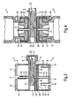
- Fig. 3
- für eine erste Ausführungsform der Transfervorrichtung einen Längsschnitt durch diese, der durch den Mittelpunkt des Radius der Einstechelemente und die Längsmittelachse des Schiebers geführt ist,
- Fig. 4
- einen Schnitt durch die
Transfervorrichtung gemäß Figur 3 mit zusätzlich veranschaulichten, in diese eingesetzten verschlossenen Fläschchen, in der ersten Verschiebestellung des Schiebers, - Fig. 5
- einen Schnitt gemäß
Figur 4, bei um die Längsmittelachse des Schiebers um 180° geschwenkter Transfervorrichtung, veranschaulicht für die zweite Verschiebestellung des Schiebers und in das Gehäuse eingesteckter Spritze, - Fig. 6
- eine räumliche Ansicht des bei der Ausführungsform nach
den Figuren 3bis 5 Verwendung findenden Schiebers, - Fig. 7
- eine zweite Ausführungsform der Transfervorrichtung mit
in diese eingesetzten Fläschchen, in einer
Schnittdarstellung gemäß Figur 5, jedoch mit in erster Verschiebestellung befindlichem Schieber, - Fig. 8
- eine Schnittdarstellung der zweiten Ausführungsform gemäß Figur 7, veranschaulicht bei in das Gehäuse eingeführter Spritze und in zweiter Verschiebestellung befindlichem Schieber,
- Fig. 9
- eine räumliche Ansicht des bei der zweiten
Ausführungsform gemäß der
Figuren 7 und 8 Verwendung findenden Schiebers.
- Fig. 1
- 3 shows a spatial view of the transfer device with two vials inserted into it,
- Fig. 2.
- a spatial view of the transfer device,
- Fig. 3
- for a first embodiment of the transfer device, a longitudinal section through it, which is guided through the center of the radius of the piercing elements and the longitudinal central axis of the slide,
- Fig. 4
- 4 shows a section through the transfer device according to FIG. 3 with additionally illustrated, closed vials inserted into it, in the first displacement position of the slide,
- Fig. 5
- 4 shows a section according to FIG. 4, with the transfer device pivoted about the longitudinal central axis of the slide by 180 °, illustrated for the second displacement position of the slide and syringe inserted into the housing,
- Fig. 6
- 3 shows a three-dimensional view of the slide used in the embodiment according to FIGS. 3 to 5,
- Fig. 7
- 5 shows a second embodiment of the transfer device with vials inserted into it, in a sectional view according to FIG. 5, but with a slide located in the first displacement position,
- Fig. 8
- 7 shows a sectional illustration of the second embodiment according to FIG. 7, illustrated with the syringe inserted into the housing and the slide in the second displacement position,
- Fig. 9
- a spatial view of the slider used in the second embodiment according to Figures 7 and 8.
Bei der in den Figuren 1 und 2 veranschaulichten Transfervorrichtung 1 ist das
Gehäuse 2 durch zwei ineinander gesteckte und miteinander verbundene
Gehäusehälften 3 und 4 gebildet. Die Gehäusehälfte 3 weist einen seitlichen
Anschluss 5 mit Außengewinde 6 zum Aufschrauben einer Verschlusskappe 7 bzw.
einer Entnahmespritze auf. Im Bereich der freien Enden weisen die Gehäusehälften
3 und 4 sich in Längsrichtung des Gehäuses 2 erstreckende Schlitze 8 auf, die
zwischen sich Gehäuselappen 9 bilden, die im Bereich ihrer freien Enden mit nach
innen gerichteten Rastvorsprüngen 10 versehen sind. In die jeweilige
Gehäusehälfte 3 bzw. 4 ist ein Glasfläschchen 11 bzw. 12 eingesetzt und mittels
der Rastvorsprünge gehalten. Im Ausgangszustand nimmt das Fläschchen 11
beispielsweise eine medizinische Flüssigkeit, das Fläschchen 12 eine zu lösende
Substanz auf. Vor dem Einsetzen des Fläschchens 12 in die Transfervorrichtung 1
herrscht in dessen Innenraum insbesondere Vakuum.In the case of the
Der Aufbau einer ersten Ausführungsform der Transfervorrichtung ist in Figur 3
veranschaulicht. Das jeweilige Gehäuseteil 3 bzw. 4 besteht aus Kunststoff und
bildet ein Bauteil mit einem Einstechdorn 13 bzw. 14, der im Bereich des
Mittelpunktes der jeweiligen Grundplatte 15 des Gehäuseteils 3 bzw. 4 mit dieser
Grundplatte 15 verbunden ist. Die Länge des jeweiligen Einstechdornes 13 bzw. 14
ist so bemessen, dass er bis zu den Rastvorsprüngen 10 reicht. Der im jeweiligen
Einstechdorn 13 bzw. 14 gebildete Strömungskanal 16 bzw. 17 setzt sich gemäß
den Abschnitten 18 bzw. 19 im Gehäuseteil 3 bzw. 4 fort. Dort wo die beiden
Gehäuseteile 3 und 4 ineinander gesteckt und miteinander fest verbunden sind, ist
ein flacher Raum gebildet, in den ein Filterelement 20 eingesetzt ist.The structure of a first embodiment of the transfer device is shown in FIG. 3
illustrated. The
Bezogen auf die Längsorientierung des Gehäuses 2, somit die Längsorientierung
der Einstechdorne 13 und 14, ist senkrecht zu diesen das Gehäuseteil 3 mit einem
Durchgang 21 versehen. In diesen ist, von der dem Anschluss 5 abgewandten
Seite, ein Schieber 22 eingesteckt, der in Figur 6 im Detail veranschaulicht ist.
Dieser ist im Wesentlichen rotationssymmetrisch ausgebildet. So weist der, der
hinteren Öffnung des Gehäuseteiles 3 zugewandte rotationssymmetrische
Abschnitt 24 des Schiebers 22 einen Wulst 25 auf, der in diesem Bereich gegen die
Wandung des Durchgangs 21 drückt und bewirkt, dass der Schieber 22 nur bei
Einleiten einer ausreichend hohen Axialkraft in diesen verschoben werden kann.
Andererseits dichtet dieser Wulst 25 den Schieber 22 gegenüber dem Durchgang
21 des Gehäuseteils 3 ab. An das vordere Ende des rotationssymmetrischen
Abschnittes 24 schließt sich im Schieber 22 eine umlaufende Nut 26 an. Von dort,
nach vorne, schließt sich ein im Wesentlichen rotationssymmetrischer Abschnitt 27
an, dessen Durchmesser demjenigen des rotationssymmetrischen Abschnittes 24,
somit desjenigen neben dem Wulst 25 entspricht. Schließlich schließt sich vorne an
den Abschnitt 27 ein im Wesentlichen rotationssymmetrischer Abschnitt 28 an, der
einen geringeren Durchmesser aufweist als der rotationssymmetrische Abschnitt
27. Die Abschnitte 27 und 28 sind mit einem V-förmigen Schlitz 29 versehen, der in
Abstand von der Nut 26 endet. Der Abschnitt 27 ist im Bereich des V-förmigen
Schlitzes 29 abgeflacht, so dass sich dort beidseits des Schlitzes 29 zwei
Führungsflächen 30 ergeben. Entsprechend, wie es der Darstellung der Figur 3 zu
entnehmen ist, wirkt ein in den Durchgang 21 ragender Vorsprung 31 mit seiner
Führungsfläche 32 mit der Führungsfläche 30 des Schiebers 22 zusammen.
Infolgedessen kann der Schieber nur in seiner Längsrichtung verschoben, nicht
aber geschwenkt werden.Relative to the longitudinal orientation of the
Die Funktion der insoweit beschriebenen Transfervorrichtung stellt sich wie folgt dar:The function of the transfer device described so far is as follows represents:
Figur 3 zeigt die Transfervorrichtung 1 in der ersten Verschiebestellung des
Schiebers 22. Hierbei fluchtet die Nut 26 des Schiebers 22 mit den Abschnitten 18
im Gehäuseteil 3; die Nut 26 steht somit in Strömungsverbindung mit den
Strömungskanälen 16 und 17 der beiden Einstechdorne 13 und 14. Der Anschluss
5 ist mittels der Kappe 7 dicht verschlossen. Hiervon ausgehend wird zunächst das
die Flüssigkeit enthaltende Fläschchen in das Gehäuseteil 3 eingesteckt. In die
Öffnung des Fläschchens 11 ist ein elastischer Stopfen 33 eingesteckt, der vom
Einstechdorn 13 durchstochen wird. In der in das Gehäuseteil 3 eingesetzten
Stellung des Fläschchens 11 hintergreifen die Rastvorsprünge 10 dieses
Gehäuseteils 3 den sich an den Flaschenhals 34 anschließenden stopfenseitigen
Wulst 35 des Fläschchens 11. Vor dem Verbinden des unter Vakuum stehenden
und das zu lösende Medikament aufnehmenden Fläschchens 12 mit der
Transfervorrichtung 1, wird diese in der in den Figuren 3 und 4 gezeigten Position
platziert, somit mit oben angeordnetem Gehäuseteil 3 und oben befindlichem
Fläschchen 11, das die Flüssigkeit aufnimmt. Dann wird das andere Fläschchen 12
in das Gehäuseteil 4 entsprechend eingeführt, wobei der Einstechdorn 14 den
Stopfen 33, der dieses Fläschchen 12 verschließt, durchdringt. Bei vollständig in
das Gehäuseteil 4 eingeführtem Fläschchen 12 hintergreifen die diesem
Gehäuseteil zugeordneten Rastvorsprünge 10 den sich an den Flaschenhals 34
dieses Fläschchens anschließenden Wulst 35. Da die Einstechdorne 13 und 14 in
die Innenräume der Fläschchen 11 und 12 ragen, wird, aufgrund des Unterdrucks
im Fläschchen 12, die Flüssigkeit vom Fläschchen 11 über den Strömungskanal 16,
die Nut 26 und den Strömungskanal 17 in das Fläschchen 12 überführt und die dort
befindliche Substanz gelöst.FIG. 3 shows the
Zum seitlichen Entnehmen der gelösten Substanz aus der Transfervorrichtung 1
wird zunächst, wie es zur Figur 4 veranschaulicht ist, die den Schieberbereich auf
der dem Wulst 25 abgewandten Seite abdichtende Verschlusskappe 7 vom
Anschluss 5 abgeschraubt, womit das Vakuum abgebaut wird. Dann wird die
Transfervorrichtung 1 mit den beiden in diese eingesetzten Fläschchen 11 und 12
um 180° um die Längsachse des Schiebers 22 in die in Figur 5 veranschaulichte
Position geschwenkt. Infolgedessen befindet sich das Fläschchen 12 mit der darin
befindlichen, gelösten Substanz oben und das leere Fläschchen 11 unten. Zum
Entnehmen der gelösten Substanz wird, wie es in Figur 5 veranschaulicht ist, ein
Spritzenkonus 36 einer nur teilweise dargestellten Spritze 37 in die konische
Öffnung des Anschlusses 5 abgedichtet eingesteckt. Beim Einführen des
Spritzenkonus 36 in den Anschluss 5 verschiebt das stirnseitige Ende 38 des
Spritzenkonus 36 den Schieber 22, wobei der Spritzenkonus 36 ein sich
verjüngendes Ende 39 des Schiebers 22 kontaktiert. In der vollständig in den
Anschluss 5 eingesetzten Stellung des Spritzenkonus 36 nimmt der Schieber 22 die
in Figur 5 gezeigte zweite Verschiebestellung ein, in der sich das der Spritze 37
abgewandte Ende des Schiebers 22 gerade noch vollständig innerhalb des
Gehäuseteils 3 befindet, und nunmehr der Strömungskanal 17 des Einstechdorns
14 über die Abschnitte 18 und 19 in Strömungsverbindung mit dem V-förmigen
Schlitz 29 im Schieber 22 steht, konkret in dem Bereich des V-förmigen Schlitzes,
der in den Abschnitt 27 eingebracht ist. Beim Aufziehen der Spritze 37 kann somit
über die Strömungsverbindung von Einstechdorn 14 und V-förmigem Schlitz 29 des
Schiebers 22 das Fläschchen 12 entleert werden.For the lateral removal of the dissolved substance from the
Bei der Ausführungsform nach den Figuren 3 bis 6 ist der Schieber starr ausgebildet, er besteht insbesondere aus Kunststoff.In the embodiment according to Figures 3 to 6, the slide is rigid trained, it consists in particular of plastic.
Eine weitere Ausführungsform der Transfervorrichtung 1 ist in den Figuren 7 bis 9
beschrieben. Diese unterscheidet sich von der ersten Ausführungsform nur
hinsichtlich des Schiebers 22 und der Gestaltung des Gehäuseteils 3. Wegen der
Übereinstimmung wird deshalb auf die vorgenannte Beschreibung verwiesen.A further embodiment of the
Bei der Ausführungsform nach den Figuren 7 bis 9 besteht der Schieber 22
insgesamt aus elastischem Material, insbesondere einem thermoplastischen
Elastomer (TPE) bzw. Gummi. Der Schieber 22 wird über den Anschluss 5 in das
Gehäuseteil 3 eingesetzt und es ist dieses im Bereich seines dem Anschluss 5
abgewandten Endes geschlossen. Diese Ausführungsform weist somit nicht die
Öffnung 23 der ersten Ausführungsform auf. Bei der Ausführungsform nach den
Figuren 7 bis 9 ist beim Schieber 22 der Abschnitt 27, der Abschnitt 28 und der V-förmige
Schlitz 29 entsprechend ausgebildet. Die umlaufende Nut 26 ist wesentlich
breiter ausgebildet als die Nut 26 der ersten Ausführungsform, in etwa so lang wie
der Abschnitt 28. Entsprechend ist der Abschnitt 24 ohne Wulst 25 gestaltet und
wesentlich kürzer als der Abschnitt 24 der ersten Ausführungsform. Der Abschnitt
24 weist zudem oben eine Abflachung 32 auf, die mit einer in dessen Bereich
angeordneten Führungsfläche 31 des Gehäuseteils 3 zusammenwirkt. Der
detaillierte Aufbau des Schiebers 22 dieser Ausführungsform ist in Figur 9
veranschaulicht.In the embodiment according to FIGS. 7 to 9 there is the
Figur 7 zeigt diese Ausführungsform in der ersten Verschiebestellung des
Schiebers, und zwar bereits in der nach oben geschwenkten Position des
Fläschchens 12 mit der darin gelösten Substanz. Der Schieber 22 liegt an der dem
Anschluss 5 abgewandten Gehäusewand 40 an. Die Strömungsverbindung der
Strömungskanäle 16 und 17 der Einstechdorne 13 bzw. 14 erfolgt über die Nut 26.
Zum Entnehmen der gelösten Substanz wird, wie es in Figur 8 veranschaulicht und
zuvor ausführlich beschrieben ist, der Spritzenkonus 36 in den Anschluss 5
eingesteckt, wobei er den Schieber 22 stirnseitig kontaktiert und im Bereich des
geschwächten Querschnittes 41, im Bereich dessen die Nut 26 definiert ist,
aufgrund der elastischen Eigenschaft des Schiebers 22 verformt. Die Verformung in
diesem Bereich des Schiebers 22 und infolgedessen die Verschiebung des dem
Spritzenkonus 36 zugewandten Bereiches des Schiebers 22 in Richtung der
Gehäusewand 40 bedingt, dass, wie es in Figur 8 veranschaulicht ist, der
Strömungskanal 17 des Einstechdornes 14 in Strömungsverbindung mit dem V-förmigen
Schlitz 29 gelangt.FIG. 7 shows this embodiment in the first shift position of the
Slider, and that already in the pivoted up position of the
Bedeutung kommt in diesem Zusammenhang dem vorzugsweise aus TPE
geformten Schieber 22 zu. Dessen elastische Eigenschaft vereinfacht die
Abdichtung des Schiebers 22 zum Gehäuseteil 3, so dass in den beiden
Verschiebestellungen des Schiebers 22 eindeutige Flüssigkeitsströme, somit ohne
Leckagen, durch die Transfervorrichtung geführt werden können. Der aus dem
thermoplastischen Elastomer bestehende Schieber 22 hat einen Federeffekt, so
dass sich das System automatisch verschließt, wenn die Spritze 37 aus dem
Anschluss 5 herausgezogen wird. In diesem Fall wird der Schieber 22 umgehend in
seine erste Verschiebestellung überführt.In this context, meaning comes preferably from TPE
shaped
Bei der ersten Ausführungsform nach den Figuren 3 bis 6, bei der der Schieber 22
starr ausgebildet ist, wird durch den Wulst 25 nicht nur die jeweilige
Ausgangsstellung des Schiebers definiert, es wird vor allem der Durchgang 21 zu
dem dem Anschluss 5 abgewandten Ende abgedichtet. Dies ist für die Funktion der
Vorrichtung wesentlich. Würde diese Dichtung nicht funktionieren, würde das
Vakuum in dem Fläschchen 12, das die zu lösende Substanz aufnimmt, abgebaut
und ein Transfer möglich. Bei der Ausführungsform der nach den Figuren 7 bis 9
mit dem elastischen Schieber 22 und dem anders gestalteten Gehäuseteil 3 dichtet
der elastische Schieber 22 aufgrund seiner Materialeigenschaften unmittelbar ab.
Außerdem kann der elastische Schieber 22 von der Entnahmeseite eingebaut
werden. Hierdurch kann auf den Durchgang 21 im Bereich des dem Anschluss 5
abgewandten Endes des Gehäuses 2 verzichtet werden, wodurch die
Abdichtungsproblematik verringert wird.In the first embodiment according to FIGS. 3 to 6, in which the
Bei beiden Ausführungsformen wird durch das Verschließen des Strömungskanals
16 verhindert, dass Luft aus dem Fläschchen 11 angesaugt werden kann. Dies ist
wichtig für die Entnahme der gelösten Substanz bzw. des gelösten Medikaments. In both embodiments, by closing the
Mit der Spritze 37 wird bei der Entnahme ein Unterdruck erzeugt, wodurch die
gelöste Substanz in die Spritze fliest. Wäre das Fläschchen 11 offen, so würde der
in der Spritze 37 erzeugte Unterdruck verringert und so das Füllen der Spritze 37
erheblich erschwert.With the
Mit der Bezugsziffer 42 ist ein kappenartiger Folienverschluss bezeichnet, der den
Wulst 35 des jeweiligen Fläschchens 11 bzw. 12 und den in diesen eingesteckten
Stopfen 33 umgibt, womit der Stopfen sicher im Fläschchen gehalten ist. The
- 11
- Transfervorrichtungtransfer device
- 22
- Gehäusecasing
- 33
- Gehäuseteilhousing part
- 44
- Gehäuseteilhousing part
- 55
- Anschlussconnection
- 66
- Gewindethread
- 77
- Verschlusskappecap
- 88th
- Schlitzslot
- 99
- Gehäuselappenhousing flap
- 1010
- Rastvorsprungcatch projection
- 1111
- Glasfläschchenglass vials
- 1212
- Glasfläschchenglass vials
- 1313
- Einstechdornspike
- 1414
- Einstechdornspike
- 1515
- Grundplattebaseplate
- 1616
- Strömungskanalflow channel
- 1717
- Strömungskanalflow channel
- 1818
- Abschnittsection
- 1919
- Abschnittsection
- 2020
- Filterelementfilter element
- 2121
- Durchführungexecution
- 2222
- Schieberpusher
- 2323
- Öffnungopening
- 2424
- Abschnittsection
- 2525
- Wulstbead
- 2626
- Nutgroove
- 2727
- Abschnittsection
- 2828
- Abschnittsection
- 2929
- Schlitzslot
- 3030
- Führungsflächeguide surface
- 3131
- Vorsprunghead Start
- 3232
- Führungsflächeguide surface
- 3333
- StopfenPlug
- 3434
- Flaschenhalsbottleneck
- 3535
- Wulstbead
- 3636
- Spritzenkonussyringe cone
- 3737
- Spritzesyringe
- 3838
- EndeThe End
- 3939
- EndeThe End
- 4040
- Gehäusewandhousing wall
- 4141
- Querschnittcross-section
- 4242
- Folienverschlussfoil closure
Claims (23)
Applications Claiming Priority (2)
| Application Number | Priority Date | Filing Date | Title |
|---|---|---|---|
| DE10310110 | 2003-03-06 | ||
| DE10310110 | 2003-03-06 |
Publications (2)
| Publication Number | Publication Date |
|---|---|
| EP1454650A1 true EP1454650A1 (en) | 2004-09-08 |
| EP1454650B1 EP1454650B1 (en) | 2007-10-10 |
Family
ID=32797879
Family Applications (1)
| Application Number | Title | Priority Date | Filing Date |
|---|---|---|---|
| EP20040003093 Expired - Fee Related EP1454650B1 (en) | 2003-03-06 | 2004-02-12 | Transfer device, in particular for medical fluids |
Country Status (10)
| Country | Link |
|---|---|
| US (1) | US7491197B2 (en) |
| EP (1) | EP1454650B1 (en) |
| JP (1) | JP2004267776A (en) |
| KR (1) | KR20040078886A (en) |
| AT (1) | ATE375181T1 (en) |
| AU (1) | AU2004200893B9 (en) |
| CA (1) | CA2459649A1 (en) |
| DE (1) | DE502004005171D1 (en) |
| ES (1) | ES2293105T3 (en) |
| IL (1) | IL160733A (en) |
Cited By (58)
| Publication number | Priority date | Publication date | Assignee | Title |
|---|---|---|---|---|
| WO2008012018A1 (en) * | 2006-07-27 | 2008-01-31 | Csl Behring Gmbh | Device for combining components by means of negative pressure under sterile conditions |
| US7326194B2 (en) | 1995-03-20 | 2008-02-05 | Medimop Medical Projects Ltd. | Fluid transfer device |
| USD616984S1 (en) | 2009-07-02 | 2010-06-01 | Medimop Medical Projects Ltd. | Vial adapter having side windows |
| USD630732S1 (en) | 2009-09-29 | 2011-01-11 | Medimop Medical Projects Ltd. | Vial adapter with female connector |
| USD641080S1 (en) | 2009-03-31 | 2011-07-05 | Medimop Medical Projects Ltd. | Medical device having syringe port with locking mechanism |
| US8016809B2 (en) | 2007-09-25 | 2011-09-13 | Medimop Medical Projects Ltd. | Liquid drug delivery devices for use with syringes with widened distal tips |
| US8021325B2 (en) | 2004-04-29 | 2011-09-20 | Medimop Medical Projects Ltd. | Liquid drug medical device |
| US8070739B2 (en) | 2005-08-11 | 2011-12-06 | Medimop Medical Projects Ltd. | Liquid drug transfer devices for failsafe correct snap fitting onto medicinal vials |
| WO2011091543A3 (en) * | 2010-02-01 | 2012-08-16 | Medmix Systems Ag | Device for removing fluids from vials |
| USD669980S1 (en) | 2010-10-15 | 2012-10-30 | Medimop Medical Projects Ltd. | Vented vial adapter |
| US8317743B2 (en) | 2007-09-18 | 2012-11-27 | Medimop Medical Projects Ltd. | Medicament mixing and injection apparatus |
| USD674088S1 (en) | 2012-02-13 | 2013-01-08 | Medimop Medical Projects Ltd. | Vial adapter |
| US8435210B2 (en) | 2007-04-17 | 2013-05-07 | Medimop Medical Projects Ltd. | Fluid control device with manually depressed actuator |
| US8608723B2 (en) | 2009-11-12 | 2013-12-17 | Medimop Medical Projects Ltd. | Fluid transfer devices with sealing arrangement |
| US8684994B2 (en) | 2010-02-24 | 2014-04-01 | Medimop Medical Projects Ltd. | Fluid transfer assembly with venting arrangement |
| US8753325B2 (en) | 2010-02-24 | 2014-06-17 | Medimop Medical Projects, Ltd. | Liquid drug transfer device with vented vial adapter |
| US8752598B2 (en) | 2011-04-17 | 2014-06-17 | Medimop Medical Projects Ltd. | Liquid drug transfer assembly |
| US8852145B2 (en) | 2010-11-14 | 2014-10-07 | Medimop Medical Projects, Ltd. | Inline liquid drug medical device having rotary flow control member |
| WO2014161846A2 (en) * | 2013-04-02 | 2014-10-09 | Parker Hannifin Manufacturing Germany GmbH & Co. KG | Fluid valve and fluid connection system |
| WO2014177347A1 (en) * | 2013-05-03 | 2014-11-06 | Hubertus Goller Gesellschaft M.B.H. | Transfer device |
| US8905994B1 (en) | 2011-10-11 | 2014-12-09 | Medimop Medical Projects, Ltd. | Valve assembly for use with liquid container and drug vial |
| USD720451S1 (en) | 2012-02-13 | 2014-12-30 | Medimop Medical Projects Ltd. | Liquid drug transfer assembly |
| US8979792B2 (en) | 2009-11-12 | 2015-03-17 | Medimop Medical Projects Ltd. | Inline liquid drug medical devices with linear displaceable sliding flow control member |
| US8998875B2 (en) | 2009-10-01 | 2015-04-07 | Medimop Medical Projects Ltd. | Vial assemblage with vial and pre-attached fluid transfer device |
| USD734868S1 (en) | 2012-11-27 | 2015-07-21 | Medimop Medical Projects Ltd. | Drug vial adapter with downwardly depending stopper |
| USD737436S1 (en) | 2012-02-13 | 2015-08-25 | Medimop Medical Projects Ltd. | Liquid drug reconstitution assembly |
| US9155680B2 (en) | 2010-03-10 | 2015-10-13 | Medmix Systems Ag | Modular filling device for an applicator |
| DE102014213948A1 (en) | 2014-07-17 | 2016-01-21 | B. Braun Melsungen Ag | Fluid connection system for medical purposes |
| US9283324B2 (en) | 2012-04-05 | 2016-03-15 | Medimop Medical Projects, Ltd | Fluid transfer devices having cartridge port with cartridge ejection arrangement |
| US9339438B2 (en) | 2012-09-13 | 2016-05-17 | Medimop Medical Projects Ltd. | Telescopic female drug vial adapter |
| USD757933S1 (en) | 2014-09-11 | 2016-05-31 | Medimop Medical Projects Ltd. | Dual vial adapter assemblage |
| USD765837S1 (en) | 2013-08-07 | 2016-09-06 | Medimop Medical Projects Ltd. | Liquid transfer device with integral vial adapter |
| USD767124S1 (en) | 2013-08-07 | 2016-09-20 | Medimop Medical Projects Ltd. | Liquid transfer device with integral vial adapter |
| US9795536B2 (en) | 2012-08-26 | 2017-10-24 | Medimop Medical Projects, Ltd. | Liquid drug transfer devices employing manual rotation for dual flow communication step actuations |
| USD801522S1 (en) | 2015-11-09 | 2017-10-31 | Medimop Medical Projects Ltd. | Fluid transfer assembly |
| US9801786B2 (en) | 2013-04-14 | 2017-10-31 | Medimop Medical Projects Ltd. | Drug container closure for mounting on open-topped drug container to form drug reconstitution assemblage for use with needleless syringe |
| US9839580B2 (en) | 2012-08-26 | 2017-12-12 | Medimop Medical Projects, Ltd. | Liquid drug transfer devices |
| US9943463B2 (en) | 2013-05-10 | 2018-04-17 | West Pharma. Services IL, Ltd. | Medical devices including vial adapter with inline dry drug module |
| FR3061655A1 (en) * | 2017-01-12 | 2018-07-13 | Arcadophta | DEVICE FOR THE EXTENDED PREPARATION OF A QUANTITY OF STERILE FLUID |
| USD832430S1 (en) | 2016-11-15 | 2018-10-30 | West Pharma. Services IL, Ltd. | Dual vial adapter assemblage |
| US10278897B2 (en) | 2015-11-25 | 2019-05-07 | West Pharma. Services IL, Ltd. | Dual vial adapter assemblage including drug vial adapter with self-sealing access valve |
| US10285907B2 (en) | 2015-01-05 | 2019-05-14 | West Pharma. Services IL, Ltd. | Dual vial adapter assemblages with quick release drug vial adapter for ensuring correct usage |
| US10357429B2 (en) | 2015-07-16 | 2019-07-23 | West Pharma. Services IL, Ltd. | Liquid drug transfer devices for secure telescopic snap fit on injection vials |
| US10646404B2 (en) | 2016-05-24 | 2020-05-12 | West Pharma. Services IL, Ltd. | Dual vial adapter assemblages including identical twin vial adapters |
| US10688295B2 (en) | 2013-08-07 | 2020-06-23 | West Pharma. Services IL, Ltd. | Liquid transfer devices for use with infusion liquid containers |
| WO2020154292A1 (en) * | 2019-01-22 | 2020-07-30 | Baxter International Inc. | Reconstitution system to administer a drug via a high vacuum vial with integrated vent conduit |
| US10765604B2 (en) | 2016-05-24 | 2020-09-08 | West Pharma. Services IL, Ltd. | Drug vial adapter assemblages including vented drug vial adapter and vented liquid vial adapter |
| US10772797B2 (en) | 2016-12-06 | 2020-09-15 | West Pharma. Services IL, Ltd. | Liquid drug transfer devices for use with intact discrete injection vial release tool |
| US10806671B2 (en) | 2016-08-21 | 2020-10-20 | West Pharma. Services IL, Ltd. | Syringe assembly |
| US10806667B2 (en) | 2016-06-06 | 2020-10-20 | West Pharma. Services IL, Ltd. | Fluid transfer devices for filling drug pump cartridges with liquid drug contents |
| US10945921B2 (en) | 2017-03-29 | 2021-03-16 | West Pharma. Services IL, Ltd. | User actuated liquid drug transfer devices for use in ready-to-use (RTU) liquid drug transfer assemblages |
| USD917693S1 (en) | 2018-07-06 | 2021-04-27 | West Pharma. Services IL, Ltd. | Medication mixing apparatus |
| USD923782S1 (en) | 2019-01-17 | 2021-06-29 | West Pharma. Services IL, Ltd. | Medication mixing apparatus |
| USD923812S1 (en) | 2019-01-16 | 2021-06-29 | West Pharma. Services IL, Ltd. | Medication mixing apparatus |
| USD954253S1 (en) | 2019-04-30 | 2022-06-07 | West Pharma. Services IL, Ltd. | Liquid transfer device |
| USD956958S1 (en) | 2020-07-13 | 2022-07-05 | West Pharma. Services IL, Ltd. | Liquid transfer device |
| US11642285B2 (en) | 2017-09-29 | 2023-05-09 | West Pharma. Services IL, Ltd. | Dual vial adapter assemblages including twin vented female vial adapters |
| US11918542B2 (en) | 2019-01-31 | 2024-03-05 | West Pharma. Services IL, Ltd. | Liquid transfer device |
Families Citing this family (47)
| Publication number | Priority date | Publication date | Assignee | Title |
|---|---|---|---|---|
| JP3883527B2 (en) * | 2003-07-17 | 2007-02-21 | ニプロ株式会社 | Transfer needle |
| JP4871019B2 (en) * | 2006-05-15 | 2012-02-08 | 日本コヴィディエン株式会社 | Liquid infusion tool |
| ES2570953T3 (en) | 2006-05-25 | 2016-05-23 | Bayer Healthcare Llc | Assembly procedure of a reconstitution device |
| US7981090B2 (en) | 2006-10-18 | 2011-07-19 | Baxter International Inc. | Luer activated device |
| US8221363B2 (en) | 2006-10-18 | 2012-07-17 | Baxter Healthcare S.A. | Luer activated device with valve element under tension |
| US7753338B2 (en) | 2006-10-23 | 2010-07-13 | Baxter International Inc. | Luer activated device with minimal fluid displacement |
| WO2009026443A2 (en) | 2007-08-21 | 2009-02-26 | Gilero, Llc | Vial access and injection system |
| CA2646265A1 (en) * | 2007-12-20 | 2009-06-20 | Tyco Healthcare Group Lp | Cap assembly for use with a prefilled lock solution syringe |
| EP2244758A4 (en) * | 2008-01-28 | 2016-12-14 | Kirk Promotion Ltd | A drainage device comprising an active filter |
| US20120156794A1 (en) * | 2008-03-19 | 2012-06-21 | Florian Schweigert | Method for the extraction and detection of fat-soluble components from biological materials |
| CA2720233A1 (en) * | 2008-04-01 | 2009-12-03 | Yukon Medical, Llc | Dual container fluid transfer device |
| JP5266990B2 (en) * | 2008-09-10 | 2013-08-21 | ニプロ株式会社 | Drug preparation device |
| WO2010061743A1 (en) * | 2008-11-25 | 2010-06-03 | 株式会社ジェイ・エム・エス | Connector |
| EP2351549B1 (en) * | 2008-11-25 | 2016-03-30 | JMS Co., Ltd. | Connector |
| JP5495006B2 (en) * | 2008-11-25 | 2014-05-21 | 株式会社ジェイ・エム・エス | connector |
| US8162914B2 (en) * | 2009-02-10 | 2012-04-24 | Kraushaar Timothy Y | Cap adapters for medicament vial and associated methods |
| US8123736B2 (en) * | 2009-02-10 | 2012-02-28 | Kraushaar Timothy Y | Cap adapters for medicament vial and associated methods |
| EP3124007A1 (en) * | 2009-04-14 | 2017-02-01 | Yukon Medical, LLC | Fluid transfer device |
| US8667996B2 (en) * | 2009-05-04 | 2014-03-11 | Valeritas, Inc. | Fluid transfer device |
| US8317741B2 (en) * | 2009-05-26 | 2012-11-27 | Kraushaar Timothy Y | Apparatus and methods for administration of reconstituted medicament |
| ES2793953T3 (en) | 2009-07-29 | 2020-11-17 | Icu Medical Inc | Fluid transfer procedures |
| US8424713B2 (en) * | 2009-12-17 | 2013-04-23 | Michael J. Bolland | Multiple container retaining device and method for using same |
| USD655017S1 (en) | 2010-06-17 | 2012-02-28 | Yukon Medical, Llc | Shroud |
| JP5844367B2 (en) | 2010-08-25 | 2016-01-13 | バクスター・インターナショナル・インコーポレイテッドBaxter International Incorp0Rated | Assembly for easy user reconfiguration |
| EP2559414A1 (en) * | 2011-08-18 | 2013-02-20 | Weibel CDS AG | Adapter for a transfer device for a fluid and transfer device |
| USD681230S1 (en) | 2011-09-08 | 2013-04-30 | Yukon Medical, Llc | Shroud |
| ES2945322T3 (en) | 2011-12-22 | 2023-06-30 | Icu Medical Inc | Fluid Transfer Devices and Methods of Use |
| JP5896228B2 (en) * | 2012-04-26 | 2016-03-30 | 株式会社ジェイ・エム・エス | Medical connector |
| USD769444S1 (en) | 2012-06-28 | 2016-10-18 | Yukon Medical, Llc | Adapter device |
| WO2014046950A1 (en) | 2012-09-24 | 2014-03-27 | Enable Injections, Llc | Medication vial and injector assemblies and methods of use |
| EP2735300A1 (en) | 2012-11-26 | 2014-05-28 | Becton Dickinson France | Adaptor for multidose medical container |
| AU2014281715B2 (en) | 2013-06-18 | 2018-09-27 | Enable Injections, Inc. | Vial transfer and injection apparatus and method |
| WO2015077184A1 (en) | 2013-11-25 | 2015-05-28 | Icu Medical, Inc. | Methods and system for filling iv bags with therapeutic fluid |
| USD747472S1 (en) | 2014-01-06 | 2016-01-12 | Zoetis Services Llc | Fluid transfer device |
| USD794183S1 (en) | 2014-03-19 | 2017-08-08 | Medimop Medical Projects Ltd. | Dual ended liquid transfer spike |
| CA159103S (en) * | 2014-04-29 | 2015-06-01 | Bayer Animal Health Gmbh | Transfer device |
| GB2534619B (en) | 2015-06-22 | 2017-06-07 | C-Major Ltd | A module for a sharps retraction device |
| EP3383343A4 (en) | 2015-12-04 | 2019-07-10 | ICU Medical, Inc. | Systems methods and components for transferring medical fluids |
| ITUA20161408A1 (en) * | 2016-03-07 | 2017-09-07 | Swisslog Italia Spa | Machine and procedure for the preparation of intravenous medicaments |
| USD851745S1 (en) | 2016-07-19 | 2019-06-18 | Icu Medical, Inc. | Medical fluid transfer system |
| CA3031529A1 (en) | 2016-07-25 | 2018-02-01 | Icu Medical, Inc. | Systems, methods, and components for trapping air bubbles in medical fluid transfer modules and systems |
| USD848370S1 (en) * | 2017-03-15 | 2019-05-14 | Gigalane Co., Ltd. | Radio frequency connector |
| CN111867545B (en) * | 2017-12-03 | 2021-11-23 | 西部制药服务有限公司(以色列) | Liquid transfer device with telescoping bottle adapter for use with infusion containers and discrete injection bottles |
| GB201816347D0 (en) * | 2018-10-07 | 2018-11-28 | Ricchetti Silvia Elisabetta | Container connectors |
| US11311458B2 (en) | 2019-09-11 | 2022-04-26 | B Braun Medical Inc. | Binary connector for drug reconstitution |
| AU2021356704A1 (en) | 2020-10-09 | 2023-06-01 | Icu Medical, Inc. | Fluid transfer device and method of use for same |
| KR102561236B1 (en) * | 2021-02-09 | 2023-07-28 | 윤지영 | Vial holder and vial holder package containing the same |
Citations (8)
| Publication number | Priority date | Publication date | Assignee | Title |
|---|---|---|---|---|
| US4423741A (en) * | 1980-01-14 | 1984-01-03 | Plasco, Inc. | Midstream sampling of catheterized liquid flow from a body cavity and improved coupling therefor |
| EP0521460B1 (en) * | 1991-07-04 | 1995-09-13 | Axel von Brand | Transfer and withdrawal spike |
| WO1997020536A1 (en) * | 1995-12-06 | 1997-06-12 | Gabriel Meyer | Device for preparing a medicinal solution reconstituted from two components |
| US5971021A (en) * | 1995-05-09 | 1999-10-26 | Ssi Technologies, Inc. | Method and valve for filling fluid system |
| US6240960B1 (en) * | 1998-02-26 | 2001-06-05 | David J. Fillmore | Back flush valve for one-way flush of drainage catheters |
| US6355023B1 (en) * | 1999-11-15 | 2002-03-12 | Gaylord Hospital | Closed system access device |
| US6379340B1 (en) * | 1995-03-20 | 2002-04-30 | Medimop Medical Projects Lts. | Fluid control device |
| DE10057153A1 (en) * | 2000-11-17 | 2002-07-04 | Seck Tilo | Valve, useful in infusion systems in medicine, is operable by the tip of a filler syringe |
Family Cites Families (26)
| Publication number | Priority date | Publication date | Assignee | Title |
|---|---|---|---|---|
| JPS4910157Y1 (en) * | 1969-08-23 | 1974-03-11 | ||
| US3757981A (en) * | 1969-11-24 | 1973-09-11 | Harris R | Valves and valve needle syringes |
| US4241754A (en) * | 1978-09-28 | 1980-12-30 | Stanadyne, Inc. | Pushbutton diverter |
| US5113904A (en) * | 1984-07-13 | 1992-05-19 | Aslanian Jerry L | Flow control device for administration of intravenous fluids |
| US4662878A (en) | 1985-11-13 | 1987-05-05 | Patents Unlimited Ltd. | Medicine vial adaptor for needleless injector |
| ATE66622T1 (en) * | 1986-04-11 | 1991-09-15 | Braun Melsungen Ag | INJECTION SHUT-OFF VALVE. |
| US5400923A (en) * | 1988-06-20 | 1995-03-28 | Helena Laboratories Corporation | Apparatus for discharging contents of a sealed container |
| ES2046039T3 (en) | 1989-11-13 | 1994-01-16 | Becton Dickinson France | STORAGE BOTTLE CONTAINING A COMPONENT OF A MEDICINAL SOLUTION. |
| US5505694A (en) * | 1990-08-22 | 1996-04-09 | Tcnl Technologies, Inc. | Apparatus and method for raising a skin wheal |
| GB9103291D0 (en) * | 1991-02-15 | 1991-04-03 | Waverley Pharma Ltd | Transfer adaptor |
| DE4121817A1 (en) | 1991-07-02 | 1993-01-07 | Hiwi Schankanlagen Gmbh | DISPENSING HEAD FOR THE PRESSURE OF LIQUIDS UNDER PRESSURE FROM A CONTAINER |
| ES1025273Y (en) | 1993-07-19 | 1994-07-01 | Mein S A Lab | INFUSION BOTTLE WITH LIQUID TRANSFER DEVICE. |
| DE19513666C1 (en) * | 1995-04-11 | 1996-11-28 | Behringwerke Ag | Device for bringing together a first liquid and a second solid or liquid component by means of negative pressure under sterile conditions |
| US5833213A (en) * | 1995-12-29 | 1998-11-10 | Rymed Technologies, Inc. | Multiple dose drug vial adapter for use with a vial having a pierceable septum and a needleless syringe |
| DE19603632C2 (en) | 1996-02-01 | 1999-06-02 | Claus H Dr Ing Backes | Adapter for a fluid withdrawal system |
| IT236233Y1 (en) * | 1997-11-26 | 2000-08-08 | Eurospital S P A | DEVICE FOR THE CONNECTION OF A PHARMACEUTICAL PRODUCT CONTAINER TO A BAG OF LIQUID PRODUCT TO CARRY OUT THE |
| US6681946B1 (en) * | 1998-02-26 | 2004-01-27 | Becton, Dickinson And Company | Resealable medical transfer set |
| US6957745B2 (en) * | 1998-04-20 | 2005-10-25 | Becton, Dickinson And Company | Transfer set |
| US6378714B1 (en) | 1998-04-20 | 2002-04-30 | Becton Dickinson And Company | Transferset for vials and other medical containers |
| US6113583A (en) | 1998-09-15 | 2000-09-05 | Baxter International Inc. | Vial connecting device for a sliding reconstitution device for a diluent container |
| US6558385B1 (en) * | 2000-09-22 | 2003-05-06 | Tissuelink Medical, Inc. | Fluid-assisted medical device |
| JP4372310B2 (en) | 2000-04-10 | 2009-11-25 | ニプロ株式会社 | Adapter for mixed injection |
| FR2817465B1 (en) | 2000-12-06 | 2003-04-25 | Technoflex Sa | RECONSTRUCTION DEVICE, PARTICULARLY FOR MIXING SUBSTANCES IN THE MEDICAL FIELD |
| US6558365B2 (en) | 2001-01-03 | 2003-05-06 | Medimop Medical Projects, Ltd. | Fluid transfer device |
| US6474375B2 (en) * | 2001-02-02 | 2002-11-05 | Baxter International Inc. | Reconstitution device and method of use |
| US6875205B2 (en) * | 2002-02-08 | 2005-04-05 | Alaris Medical Systems, Inc. | Vial adapter having a needle-free valve for use with vial closures of different sizes |
-
2004
- 2004-02-12 ES ES04003093T patent/ES2293105T3/en not_active Expired - Lifetime
- 2004-02-12 AT AT04003093T patent/ATE375181T1/en active
- 2004-02-12 EP EP20040003093 patent/EP1454650B1/en not_active Expired - Fee Related
- 2004-02-12 DE DE200450005171 patent/DE502004005171D1/en not_active Expired - Lifetime
- 2004-03-04 AU AU2004200893A patent/AU2004200893B9/en not_active Ceased
- 2004-03-04 KR KR1020040014606A patent/KR20040078886A/en not_active Application Discontinuation
- 2004-03-04 CA CA 2459649 patent/CA2459649A1/en not_active Abandoned
- 2004-03-04 IL IL160733A patent/IL160733A/en active IP Right Grant
- 2004-03-05 JP JP2004061918A patent/JP2004267776A/en active Pending
- 2004-03-05 US US10/793,210 patent/US7491197B2/en active Active
Patent Citations (8)
| Publication number | Priority date | Publication date | Assignee | Title |
|---|---|---|---|---|
| US4423741A (en) * | 1980-01-14 | 1984-01-03 | Plasco, Inc. | Midstream sampling of catheterized liquid flow from a body cavity and improved coupling therefor |
| EP0521460B1 (en) * | 1991-07-04 | 1995-09-13 | Axel von Brand | Transfer and withdrawal spike |
| US6379340B1 (en) * | 1995-03-20 | 2002-04-30 | Medimop Medical Projects Lts. | Fluid control device |
| US5971021A (en) * | 1995-05-09 | 1999-10-26 | Ssi Technologies, Inc. | Method and valve for filling fluid system |
| WO1997020536A1 (en) * | 1995-12-06 | 1997-06-12 | Gabriel Meyer | Device for preparing a medicinal solution reconstituted from two components |
| US6240960B1 (en) * | 1998-02-26 | 2001-06-05 | David J. Fillmore | Back flush valve for one-way flush of drainage catheters |
| US6355023B1 (en) * | 1999-11-15 | 2002-03-12 | Gaylord Hospital | Closed system access device |
| DE10057153A1 (en) * | 2000-11-17 | 2002-07-04 | Seck Tilo | Valve, useful in infusion systems in medicine, is operable by the tip of a filler syringe |
Cited By (78)
| Publication number | Priority date | Publication date | Assignee | Title |
|---|---|---|---|---|
| US7326194B2 (en) | 1995-03-20 | 2008-02-05 | Medimop Medical Projects Ltd. | Fluid transfer device |
| US7632261B2 (en) | 1995-03-20 | 2009-12-15 | Medimop Medical Projects, Ltd. | Fluid transfer device |
| US8021325B2 (en) | 2004-04-29 | 2011-09-20 | Medimop Medical Projects Ltd. | Liquid drug medical device |
| US8066688B2 (en) | 2004-04-29 | 2011-11-29 | Medimop Medical Projects Ltd. | Liquid drug medical device |
| US8070739B2 (en) | 2005-08-11 | 2011-12-06 | Medimop Medical Projects Ltd. | Liquid drug transfer devices for failsafe correct snap fitting onto medicinal vials |
| DE102006035545B4 (en) * | 2006-07-27 | 2008-04-30 | Csl Behring Gmbh | Device for bringing components together by means of negative pressure under sterile conditions |
| WO2008012018A1 (en) * | 2006-07-27 | 2008-01-31 | Csl Behring Gmbh | Device for combining components by means of negative pressure under sterile conditions |
| US8051884B2 (en) | 2006-07-27 | 2011-11-08 | Csl Behring Gmbh | Device for combining components by means of negative pressure under sterile conditions |
| DE102006035545A1 (en) * | 2006-07-27 | 2008-01-31 | Csl Behring Gmbh | Device for bringing components together by means of negative pressure under sterile conditions |
| US8435210B2 (en) | 2007-04-17 | 2013-05-07 | Medimop Medical Projects Ltd. | Fluid control device with manually depressed actuator |
| US8317743B2 (en) | 2007-09-18 | 2012-11-27 | Medimop Medical Projects Ltd. | Medicament mixing and injection apparatus |
| US8016809B2 (en) | 2007-09-25 | 2011-09-13 | Medimop Medical Projects Ltd. | Liquid drug delivery devices for use with syringes with widened distal tips |
| USD641080S1 (en) | 2009-03-31 | 2011-07-05 | Medimop Medical Projects Ltd. | Medical device having syringe port with locking mechanism |
| USD616984S1 (en) | 2009-07-02 | 2010-06-01 | Medimop Medical Projects Ltd. | Vial adapter having side windows |
| USD630732S1 (en) | 2009-09-29 | 2011-01-11 | Medimop Medical Projects Ltd. | Vial adapter with female connector |
| US8998875B2 (en) | 2009-10-01 | 2015-04-07 | Medimop Medical Projects Ltd. | Vial assemblage with vial and pre-attached fluid transfer device |
| US9132063B2 (en) | 2009-11-12 | 2015-09-15 | Medimop Medical Projects Ltd. | Inline liquid drug medical devices with linear displaceable sliding flow control member |
| US8608723B2 (en) | 2009-11-12 | 2013-12-17 | Medimop Medical Projects Ltd. | Fluid transfer devices with sealing arrangement |
| US8979792B2 (en) | 2009-11-12 | 2015-03-17 | Medimop Medical Projects Ltd. | Inline liquid drug medical devices with linear displaceable sliding flow control member |
| WO2011091543A3 (en) * | 2010-02-01 | 2012-08-16 | Medmix Systems Ag | Device for removing fluids from vials |
| US8684994B2 (en) | 2010-02-24 | 2014-04-01 | Medimop Medical Projects Ltd. | Fluid transfer assembly with venting arrangement |
| US8753325B2 (en) | 2010-02-24 | 2014-06-17 | Medimop Medical Projects, Ltd. | Liquid drug transfer device with vented vial adapter |
| US9155680B2 (en) | 2010-03-10 | 2015-10-13 | Medmix Systems Ag | Modular filling device for an applicator |
| USD669980S1 (en) | 2010-10-15 | 2012-10-30 | Medimop Medical Projects Ltd. | Vented vial adapter |
| US8852145B2 (en) | 2010-11-14 | 2014-10-07 | Medimop Medical Projects, Ltd. | Inline liquid drug medical device having rotary flow control member |
| US8752598B2 (en) | 2011-04-17 | 2014-06-17 | Medimop Medical Projects Ltd. | Liquid drug transfer assembly |
| US8905994B1 (en) | 2011-10-11 | 2014-12-09 | Medimop Medical Projects, Ltd. | Valve assembly for use with liquid container and drug vial |
| USD674088S1 (en) | 2012-02-13 | 2013-01-08 | Medimop Medical Projects Ltd. | Vial adapter |
| USD720451S1 (en) | 2012-02-13 | 2014-12-30 | Medimop Medical Projects Ltd. | Liquid drug transfer assembly |
| USD737436S1 (en) | 2012-02-13 | 2015-08-25 | Medimop Medical Projects Ltd. | Liquid drug reconstitution assembly |
| US9283324B2 (en) | 2012-04-05 | 2016-03-15 | Medimop Medical Projects, Ltd | Fluid transfer devices having cartridge port with cartridge ejection arrangement |
| US9795536B2 (en) | 2012-08-26 | 2017-10-24 | Medimop Medical Projects, Ltd. | Liquid drug transfer devices employing manual rotation for dual flow communication step actuations |
| US9839580B2 (en) | 2012-08-26 | 2017-12-12 | Medimop Medical Projects, Ltd. | Liquid drug transfer devices |
| US10299990B2 (en) | 2012-08-26 | 2019-05-28 | West Pharma. Services IL, Ltd. | Liquid drug transfer devices |
| US9339438B2 (en) | 2012-09-13 | 2016-05-17 | Medimop Medical Projects Ltd. | Telescopic female drug vial adapter |
| USD734868S1 (en) | 2012-11-27 | 2015-07-21 | Medimop Medical Projects Ltd. | Drug vial adapter with downwardly depending stopper |
| WO2014161846A3 (en) * | 2013-04-02 | 2014-12-11 | Parker Hannifin Manufacturing Germany GmbH & Co. KG | Fluid valve and fluid connection system |
| WO2014161846A2 (en) * | 2013-04-02 | 2014-10-09 | Parker Hannifin Manufacturing Germany GmbH & Co. KG | Fluid valve and fluid connection system |
| US10123941B2 (en) | 2013-04-02 | 2018-11-13 | Parker Hannifin Manufacturing Germany GmbH & Co. KG | Fluid valve and fluid connection system |
| US11298294B2 (en) | 2013-04-02 | 2022-04-12 | Parker Hannifin Manufacturing Germany GmbH & Co. KG | Fluid valve and fluid connection system |
| US9801786B2 (en) | 2013-04-14 | 2017-10-31 | Medimop Medical Projects Ltd. | Drug container closure for mounting on open-topped drug container to form drug reconstitution assemblage for use with needleless syringe |
| WO2014177347A1 (en) * | 2013-05-03 | 2014-11-06 | Hubertus Goller Gesellschaft M.B.H. | Transfer device |
| AT514328B1 (en) * | 2013-05-03 | 2014-12-15 | Hubertus Goller Ges M B H | transfer device |
| AT514328A4 (en) * | 2013-05-03 | 2014-12-15 | Hubertus Goller Ges M B H | transfer device |
| US9943463B2 (en) | 2013-05-10 | 2018-04-17 | West Pharma. Services IL, Ltd. | Medical devices including vial adapter with inline dry drug module |
| USD765837S1 (en) | 2013-08-07 | 2016-09-06 | Medimop Medical Projects Ltd. | Liquid transfer device with integral vial adapter |
| USD767124S1 (en) | 2013-08-07 | 2016-09-20 | Medimop Medical Projects Ltd. | Liquid transfer device with integral vial adapter |
| US10688295B2 (en) | 2013-08-07 | 2020-06-23 | West Pharma. Services IL, Ltd. | Liquid transfer devices for use with infusion liquid containers |
| DE102014213948A1 (en) | 2014-07-17 | 2016-01-21 | B. Braun Melsungen Ag | Fluid connection system for medical purposes |
| DE102014213948B4 (en) | 2014-07-17 | 2021-09-23 | B. Braun Melsungen Aktiengesellschaft | Fluid connection system for medical purposes |
| USD757933S1 (en) | 2014-09-11 | 2016-05-31 | Medimop Medical Projects Ltd. | Dual vial adapter assemblage |
| US10285907B2 (en) | 2015-01-05 | 2019-05-14 | West Pharma. Services IL, Ltd. | Dual vial adapter assemblages with quick release drug vial adapter for ensuring correct usage |
| US10357429B2 (en) | 2015-07-16 | 2019-07-23 | West Pharma. Services IL, Ltd. | Liquid drug transfer devices for secure telescopic snap fit on injection vials |
| USD801522S1 (en) | 2015-11-09 | 2017-10-31 | Medimop Medical Projects Ltd. | Fluid transfer assembly |
| US10278897B2 (en) | 2015-11-25 | 2019-05-07 | West Pharma. Services IL, Ltd. | Dual vial adapter assemblage including drug vial adapter with self-sealing access valve |
| US10646404B2 (en) | 2016-05-24 | 2020-05-12 | West Pharma. Services IL, Ltd. | Dual vial adapter assemblages including identical twin vial adapters |
| US10765604B2 (en) | 2016-05-24 | 2020-09-08 | West Pharma. Services IL, Ltd. | Drug vial adapter assemblages including vented drug vial adapter and vented liquid vial adapter |
| US10806667B2 (en) | 2016-06-06 | 2020-10-20 | West Pharma. Services IL, Ltd. | Fluid transfer devices for filling drug pump cartridges with liquid drug contents |
| US10806671B2 (en) | 2016-08-21 | 2020-10-20 | West Pharma. Services IL, Ltd. | Syringe assembly |
| USD832430S1 (en) | 2016-11-15 | 2018-10-30 | West Pharma. Services IL, Ltd. | Dual vial adapter assemblage |
| US11786443B2 (en) | 2016-12-06 | 2023-10-17 | West Pharma. Services IL, Ltd. | Liquid transfer device with integral telescopic vial adapter for use with infusion liquid container and discrete injection vial |
| US10772797B2 (en) | 2016-12-06 | 2020-09-15 | West Pharma. Services IL, Ltd. | Liquid drug transfer devices for use with intact discrete injection vial release tool |
| US10772798B2 (en) | 2016-12-06 | 2020-09-15 | West Pharma Services Il, Ltd. | Liquid transfer device with integral telescopic vial adapter for use with infusion liquid container and discrete injection vial |
| FR3061655A1 (en) * | 2017-01-12 | 2018-07-13 | Arcadophta | DEVICE FOR THE EXTENDED PREPARATION OF A QUANTITY OF STERILE FLUID |
| EP3348249A1 (en) * | 2017-01-12 | 2018-07-18 | Arcadophta | Device for extemporaneous preparation of an amount of sterile fluid |
| US10945921B2 (en) | 2017-03-29 | 2021-03-16 | West Pharma. Services IL, Ltd. | User actuated liquid drug transfer devices for use in ready-to-use (RTU) liquid drug transfer assemblages |
| US11642285B2 (en) | 2017-09-29 | 2023-05-09 | West Pharma. Services IL, Ltd. | Dual vial adapter assemblages including twin vented female vial adapters |
| USD917693S1 (en) | 2018-07-06 | 2021-04-27 | West Pharma. Services IL, Ltd. | Medication mixing apparatus |
| USD923812S1 (en) | 2019-01-16 | 2021-06-29 | West Pharma. Services IL, Ltd. | Medication mixing apparatus |
| USD923782S1 (en) | 2019-01-17 | 2021-06-29 | West Pharma. Services IL, Ltd. | Medication mixing apparatus |
| US11484469B2 (en) | 2019-01-22 | 2022-11-01 | Baxter International Inc. | Reconstitution system to administer a drug via a high vacuum vial with integrated vent conduit |
| WO2020154292A1 (en) * | 2019-01-22 | 2020-07-30 | Baxter International Inc. | Reconstitution system to administer a drug via a high vacuum vial with integrated vent conduit |
| US11883363B2 (en) | 2019-01-22 | 2024-01-30 | Baxter International Inc. | Reconstitution system to administer a drug via a high vacuum vial with integrated vent conduit |
| US11918542B2 (en) | 2019-01-31 | 2024-03-05 | West Pharma. Services IL, Ltd. | Liquid transfer device |
| USD954253S1 (en) | 2019-04-30 | 2022-06-07 | West Pharma. Services IL, Ltd. | Liquid transfer device |
| US11484470B2 (en) | 2019-04-30 | 2022-11-01 | West Pharma. Services IL, Ltd. | Liquid transfer device with dual lumen IV spike |
| US11786442B2 (en) | 2019-04-30 | 2023-10-17 | West Pharma. Services IL, Ltd. | Liquid transfer device with dual lumen IV spike |
| USD956958S1 (en) | 2020-07-13 | 2022-07-05 | West Pharma. Services IL, Ltd. | Liquid transfer device |
Also Published As
| Publication number | Publication date |
|---|---|
| ATE375181T1 (en) | 2007-10-15 |
| US7491197B2 (en) | 2009-02-17 |
| US20040225274A1 (en) | 2004-11-11 |
| AU2004200893B2 (en) | 2010-03-11 |
| IL160733A (en) | 2009-11-18 |
| AU2004200893A1 (en) | 2004-09-23 |
| ES2293105T3 (en) | 2008-03-16 |
| AU2004200893B9 (en) | 2010-04-15 |
| KR20040078886A (en) | 2004-09-13 |
| DE502004005171D1 (en) | 2007-11-22 |
| JP2004267776A (en) | 2004-09-30 |
| CA2459649A1 (en) | 2004-09-06 |
| EP1454650B1 (en) | 2007-10-10 |
| IL160733A0 (en) | 2004-08-31 |
Similar Documents
| Publication | Publication Date | Title |
|---|---|---|
| EP1454650B1 (en) | Transfer device, in particular for medical fluids | |
| EP2667838B1 (en) | Connecting device for connecting a first reservoir to a second reservoir | |
| DE19828651C2 (en) | Connector element with closure part for medical technology | |
| DE69922034T2 (en) | PRE-FILLED INJECTION DEVICE FOR ONCE USE | |
| AT500247B1 (en) | RECEIVING DEVICE, ESPECIALLY FOR BODY FLUIDS, WITH A SEPARATION DEVICE AND SEPARATING DEVICE THEREFOR | |
| AT514328B1 (en) | transfer device | |
| EP2497721B1 (en) | Cartridge comprising several components | |
| DE69636179T2 (en) | Valve housing for medical coupling point | |
| DE10247963A1 (en) | Pre-filled syringe with membrane seal, has cylinder, connector and sealing membrane constructed in one piece as plastic injection-molded part | |
| EP1454609A1 (en) | Transfer device | |
| DE102012113002A1 (en) | Transfer device for removing or transferring a fluid | |
| DE102006031712B3 (en) | Fluid transfer device, has guide, block and anti-block that are provided to block movement of transfer part in direction of bottle containing medicament and to release movement when pin transfixes connector of bottle containing fluid | |
| WO2016120155A1 (en) | Device for transferring a fluid between a storage container and at least one further container for use | |
| DE3132323A1 (en) | Injection part for infusion devices | |
| DE102006040670A1 (en) | Device for removing liquids | |
| DE102004044288A1 (en) | Device for connecting a tubular part, in particular a cannula, to the inside of a bottle or the like | |
| DE102006020286A1 (en) | Syringe extracting microliter quantities of fluid from container, has canula with side opening sealed in cover, when extracted from container | |
| EP3204669B1 (en) | Drainage connector | |
| DE10251644B4 (en) | tap | |
| EP3250173A1 (en) | Hollow needle assembly | |
| DE10163716C1 (en) | The blood collection device | |
| DE4332087A1 (en) | Closure and removal device | |
| WO2016062418A1 (en) | Peg probe having protected manual valve operation | |
| DE102012016936A1 (en) | Device for taking body fluids and method for mounting such a device | |
| DE102016203519A1 (en) | Valve body and connection device for a medical infusion system |
Legal Events
| Date | Code | Title | Description |
|---|---|---|---|
| PUAI | Public reference made under article 153(3) epc to a published international application that has entered the european phase |
Free format text: ORIGINAL CODE: 0009012 |
|
| AK | Designated contracting states |
Kind code of ref document: A1 Designated state(s): AT BE BG CH CY CZ DE DK EE ES FI FR GB GR HU IE IT LI LU MC NL PT RO SE SI SK TR |
|
| AX | Request for extension of the european patent |
Extension state: AL LT LV MK |
|
| 17P | Request for examination filed |
Effective date: 20050308 |
|
| AKX | Designation fees paid |
Designated state(s): AT BE BG CH CY CZ DE DK EE ES FI FR GB GR HU IE IT LI LU MC NL PT RO SE SI SK TR |
|
| 17Q | First examination report despatched |
Effective date: 20060418 |
|
| RAP1 | Party data changed (applicant data changed or rights of an application transferred) |
Owner name: CSL BEHRING GMBH |
|
| GRAP | Despatch of communication of intention to grant a patent |
Free format text: ORIGINAL CODE: EPIDOSNIGR1 |
|
| GRAS | Grant fee paid |
Free format text: ORIGINAL CODE: EPIDOSNIGR3 |
|
| GRAA | (expected) grant |
Free format text: ORIGINAL CODE: 0009210 |
|
| AK | Designated contracting states |
Kind code of ref document: B1 Designated state(s): AT BE BG CH CY CZ DE DK EE ES FI FR GB GR HU IE IT LI LU MC NL PT RO SE SI SK TR |
|
| REG | Reference to a national code |
Ref country code: GB Ref legal event code: FG4D Free format text: NOT ENGLISH |
|
| REG | Reference to a national code |
Ref country code: CH Ref legal event code: EP |
|
| REG | Reference to a national code |
Ref country code: IE Ref legal event code: FG4D Free format text: LANGUAGE OF EP DOCUMENT: GERMAN |
|
| REF | Corresponds to: |
Ref document number: 502004005171 Country of ref document: DE Date of ref document: 20071122 Kind code of ref document: P |
|
| GBT | Gb: translation of ep patent filed (gb section 77(6)(a)/1977) |
Effective date: 20080102 |
|
| ET | Fr: translation filed | ||
| REG | Reference to a national code |
Ref country code: ES Ref legal event code: FG2A Ref document number: 2293105 Country of ref document: ES Kind code of ref document: T3 |
|
| NLV1 | Nl: lapsed or annulled due to failure to fulfill the requirements of art. 29p and 29m of the patents act | ||
| PG25 | Lapsed in a contracting state [announced via postgrant information from national office to epo] |
Ref country code: SE Free format text: LAPSE BECAUSE OF FAILURE TO SUBMIT A TRANSLATION OF THE DESCRIPTION OR TO PAY THE FEE WITHIN THE PRESCRIBED TIME-LIMIT Effective date: 20080110 Ref country code: NL Free format text: LAPSE BECAUSE OF FAILURE TO SUBMIT A TRANSLATION OF THE DESCRIPTION OR TO PAY THE FEE WITHIN THE PRESCRIBED TIME-LIMIT Effective date: 20071010 |
|
| PG25 | Lapsed in a contracting state [announced via postgrant information from national office to epo] |
Ref country code: PT Free format text: LAPSE BECAUSE OF FAILURE TO SUBMIT A TRANSLATION OF THE DESCRIPTION OR TO PAY THE FEE WITHIN THE PRESCRIBED TIME-LIMIT Effective date: 20080310 Ref country code: BG Free format text: LAPSE BECAUSE OF FAILURE TO SUBMIT A TRANSLATION OF THE DESCRIPTION OR TO PAY THE FEE WITHIN THE PRESCRIBED TIME-LIMIT Effective date: 20080110 |
|
| PG25 | Lapsed in a contracting state [announced via postgrant information from national office to epo] |
Ref country code: DK Free format text: LAPSE BECAUSE OF FAILURE TO SUBMIT A TRANSLATION OF THE DESCRIPTION OR TO PAY THE FEE WITHIN THE PRESCRIBED TIME-LIMIT Effective date: 20071010 Ref country code: CZ Free format text: LAPSE BECAUSE OF FAILURE TO SUBMIT A TRANSLATION OF THE DESCRIPTION OR TO PAY THE FEE WITHIN THE PRESCRIBED TIME-LIMIT Effective date: 20071010 |
|
| PLBE | No opposition filed within time limit |
Free format text: ORIGINAL CODE: 0009261 |
|
| STAA | Information on the status of an ep patent application or granted ep patent |
Free format text: STATUS: NO OPPOSITION FILED WITHIN TIME LIMIT |
|
| PG25 | Lapsed in a contracting state [announced via postgrant information from national office to epo] |
Ref country code: SK Free format text: LAPSE BECAUSE OF FAILURE TO SUBMIT A TRANSLATION OF THE DESCRIPTION OR TO PAY THE FEE WITHIN THE PRESCRIBED TIME-LIMIT Effective date: 20071010 Ref country code: RO Free format text: LAPSE BECAUSE OF FAILURE TO SUBMIT A TRANSLATION OF THE DESCRIPTION OR TO PAY THE FEE WITHIN THE PRESCRIBED TIME-LIMIT Effective date: 20071010 |
|
| 26N | No opposition filed |
Effective date: 20080711 |
|
| PG25 | Lapsed in a contracting state [announced via postgrant information from national office to epo] |
Ref country code: MC Free format text: LAPSE BECAUSE OF NON-PAYMENT OF DUE FEES Effective date: 20080228 |
|
| PG25 | Lapsed in a contracting state [announced via postgrant information from national office to epo] |
Ref country code: GR Free format text: LAPSE BECAUSE OF FAILURE TO SUBMIT A TRANSLATION OF THE DESCRIPTION OR TO PAY THE FEE WITHIN THE PRESCRIBED TIME-LIMIT Effective date: 20080111 Ref country code: EE Free format text: LAPSE BECAUSE OF FAILURE TO SUBMIT A TRANSLATION OF THE DESCRIPTION OR TO PAY THE FEE WITHIN THE PRESCRIBED TIME-LIMIT Effective date: 20071010 |
|
| PG25 | Lapsed in a contracting state [announced via postgrant information from national office to epo] |
Ref country code: FI Free format text: LAPSE BECAUSE OF FAILURE TO SUBMIT A TRANSLATION OF THE DESCRIPTION OR TO PAY THE FEE WITHIN THE PRESCRIBED TIME-LIMIT Effective date: 20071010 |
|
| PG25 | Lapsed in a contracting state [announced via postgrant information from national office to epo] |
Ref country code: SI Free format text: LAPSE BECAUSE OF FAILURE TO SUBMIT A TRANSLATION OF THE DESCRIPTION OR TO PAY THE FEE WITHIN THE PRESCRIBED TIME-LIMIT Effective date: 20071010 |
|
| PG25 | Lapsed in a contracting state [announced via postgrant information from national office to epo] |
Ref country code: CY Free format text: LAPSE BECAUSE OF FAILURE TO SUBMIT A TRANSLATION OF THE DESCRIPTION OR TO PAY THE FEE WITHIN THE PRESCRIBED TIME-LIMIT Effective date: 20071010 |
|
| PG25 | Lapsed in a contracting state [announced via postgrant information from national office to epo] |
Ref country code: HU Free format text: LAPSE BECAUSE OF FAILURE TO SUBMIT A TRANSLATION OF THE DESCRIPTION OR TO PAY THE FEE WITHIN THE PRESCRIBED TIME-LIMIT Effective date: 20080411 |
|
| PG25 | Lapsed in a contracting state [announced via postgrant information from national office to epo] |
Ref country code: TR Free format text: LAPSE BECAUSE OF FAILURE TO SUBMIT A TRANSLATION OF THE DESCRIPTION OR TO PAY THE FEE WITHIN THE PRESCRIBED TIME-LIMIT Effective date: 20071010 |
|
| PGFP | Annual fee paid to national office [announced via postgrant information from national office to epo] |
Ref country code: LU Payment date: 20131227 Year of fee payment: 11 |
|
| PGFP | Annual fee paid to national office [announced via postgrant information from national office to epo] |
Ref country code: IE Payment date: 20140211 Year of fee payment: 11 |
|
| PGFP | Annual fee paid to national office [announced via postgrant information from national office to epo] |
Ref country code: BE Payment date: 20140214 Year of fee payment: 11 |
|
| PG25 | Lapsed in a contracting state [announced via postgrant information from national office to epo] |
Ref country code: BE Free format text: LAPSE BECAUSE OF NON-PAYMENT OF DUE FEES Effective date: 20150228 |
|
| PG25 | Lapsed in a contracting state [announced via postgrant information from national office to epo] |
Ref country code: LU Free format text: LAPSE BECAUSE OF NON-PAYMENT OF DUE FEES Effective date: 20150212 |
|
| REG | Reference to a national code |
Ref country code: IE Ref legal event code: MM4A |
|
| REG | Reference to a national code |
Ref country code: FR Ref legal event code: PLFP Year of fee payment: 13 |
|
| PG25 | Lapsed in a contracting state [announced via postgrant information from national office to epo] |
Ref country code: IE Free format text: LAPSE BECAUSE OF NON-PAYMENT OF DUE FEES Effective date: 20150212 |
|
| REG | Reference to a national code |
Ref country code: FR Ref legal event code: PLFP Year of fee payment: 14 |
|
| REG | Reference to a national code |
Ref country code: FR Ref legal event code: PLFP Year of fee payment: 15 |
|
| PGFP | Annual fee paid to national office [announced via postgrant information from national office to epo] |
Ref country code: ES Payment date: 20200302 Year of fee payment: 17 Ref country code: GB Payment date: 20200206 Year of fee payment: 17 Ref country code: AT Payment date: 20200127 Year of fee payment: 17 Ref country code: IT Payment date: 20200128 Year of fee payment: 17 Ref country code: DE Payment date: 20200229 Year of fee payment: 17 |
|
| PGFP | Annual fee paid to national office [announced via postgrant information from national office to epo] |
Ref country code: CH Payment date: 20200213 Year of fee payment: 17 |
|
| PGFP | Annual fee paid to national office [announced via postgrant information from national office to epo] |
Ref country code: FR Payment date: 20200113 Year of fee payment: 17 |
|
| REG | Reference to a national code |
Ref country code: DE Ref legal event code: R119 Ref document number: 502004005171 Country of ref document: DE |
|
| REG | Reference to a national code |
Ref country code: AT Ref legal event code: MM01 Ref document number: 375181 Country of ref document: AT Kind code of ref document: T Effective date: 20210212 |
|
| GBPC | Gb: european patent ceased through non-payment of renewal fee |
Effective date: 20210212 |
|
| PG25 | Lapsed in a contracting state [announced via postgrant information from national office to epo] |
Ref country code: LI Free format text: LAPSE BECAUSE OF NON-PAYMENT OF DUE FEES Effective date: 20210228 Ref country code: CH Free format text: LAPSE BECAUSE OF NON-PAYMENT OF DUE FEES Effective date: 20210228 Ref country code: AT Free format text: LAPSE BECAUSE OF NON-PAYMENT OF DUE FEES Effective date: 20210212 |
|
| PG25 | Lapsed in a contracting state [announced via postgrant information from national office to epo] |
Ref country code: FR Free format text: LAPSE BECAUSE OF NON-PAYMENT OF DUE FEES Effective date: 20210228 Ref country code: GB Free format text: LAPSE BECAUSE OF NON-PAYMENT OF DUE FEES Effective date: 20210212 Ref country code: DE Free format text: LAPSE BECAUSE OF NON-PAYMENT OF DUE FEES Effective date: 20210901 |
|
| PG25 | Lapsed in a contracting state [announced via postgrant information from national office to epo] |
Ref country code: IT Free format text: LAPSE BECAUSE OF NON-PAYMENT OF DUE FEES Effective date: 20210212 |
|
| REG | Reference to a national code |
Ref country code: ES Ref legal event code: FD2A Effective date: 20220510 |
|
| PG25 | Lapsed in a contracting state [announced via postgrant information from national office to epo] |
Ref country code: ES Free format text: LAPSE BECAUSE OF NON-PAYMENT OF DUE FEES Effective date: 20210213 |