EP2497721B1 - Cartridge comprising several components - Google Patents
Cartridge comprising several components Download PDFInfo
- Publication number
- EP2497721B1 EP2497721B1 EP12155805.0A EP12155805A EP2497721B1 EP 2497721 B1 EP2497721 B1 EP 2497721B1 EP 12155805 A EP12155805 A EP 12155805A EP 2497721 B1 EP2497721 B1 EP 2497721B1
- Authority
- EP
- European Patent Office
- Prior art keywords
- mixer
- housing
- mixer housing
- rotary
- component cartridge
- Prior art date
- Legal status (The legal status is an assumption and is not a legal conclusion. Google has not performed a legal analysis and makes no representation as to the accuracy of the status listed.)
- Active
Links
- 238000002156 mixing Methods 0.000 claims description 25
- 238000007789 sealing Methods 0.000 claims description 15
- 238000006073 displacement reaction Methods 0.000 claims description 14
- 238000000465 moulding Methods 0.000 claims description 4
- 230000015572 biosynthetic process Effects 0.000 claims description 2
- 238000007373 indentation Methods 0.000 claims 2
- 230000003993 interaction Effects 0.000 claims 1
- 238000007599 discharging Methods 0.000 abstract description 3
- 238000002347 injection Methods 0.000 abstract 1
- 239000007924 injection Substances 0.000 abstract 1
- 239000000463 material Substances 0.000 description 9
- 239000004743 Polypropylene Substances 0.000 description 3
- -1 polypropylene Polymers 0.000 description 3
- 229920001155 polypropylene Polymers 0.000 description 3
- 229930040373 Paraformaldehyde Natural products 0.000 description 2
- XECAHXYUAAWDEL-UHFFFAOYSA-N acrylonitrile butadiene styrene Chemical compound C=CC=C.C=CC#N.C=CC1=CC=CC=C1 XECAHXYUAAWDEL-UHFFFAOYSA-N 0.000 description 2
- 229920000122 acrylonitrile butadiene styrene Polymers 0.000 description 2
- 239000004676 acrylonitrile butadiene styrene Substances 0.000 description 2
- 239000011324 bead Substances 0.000 description 2
- 230000008878 coupling Effects 0.000 description 2
- 238000010168 coupling process Methods 0.000 description 2
- 238000005859 coupling reaction Methods 0.000 description 2
- 239000004033 plastic Substances 0.000 description 2
- 229920003023 plastic Polymers 0.000 description 2
- 229920006324 polyoxymethylene Polymers 0.000 description 2
- 230000002028 premature Effects 0.000 description 2
- 101100328887 Caenorhabditis elegans col-34 gene Proteins 0.000 description 1
- 239000004793 Polystyrene Substances 0.000 description 1
- 239000000853 adhesive Substances 0.000 description 1
- 230000001070 adhesive effect Effects 0.000 description 1
- 230000005540 biological transmission Effects 0.000 description 1
- 150000001875 compounds Chemical class 0.000 description 1
- 230000018044 dehydration Effects 0.000 description 1
- 238000006297 dehydration reaction Methods 0.000 description 1
- 238000011161 development Methods 0.000 description 1
- 230000018109 developmental process Effects 0.000 description 1
- 239000012530 fluid Substances 0.000 description 1
- 239000000203 mixture Substances 0.000 description 1
- 230000002093 peripheral effect Effects 0.000 description 1
- 229920002223 polystyrene Polymers 0.000 description 1
- 230000000007 visual effect Effects 0.000 description 1
Images


Classifications
-
- B—PERFORMING OPERATIONS; TRANSPORTING
- B65—CONVEYING; PACKING; STORING; HANDLING THIN OR FILAMENTARY MATERIAL
- B65D—CONTAINERS FOR STORAGE OR TRANSPORT OF ARTICLES OR MATERIALS, e.g. BAGS, BARRELS, BOTTLES, BOXES, CANS, CARTONS, CRATES, DRUMS, JARS, TANKS, HOPPERS, FORWARDING CONTAINERS; ACCESSORIES, CLOSURES, OR FITTINGS THEREFOR; PACKAGING ELEMENTS; PACKAGES
- B65D81/00—Containers, packaging elements, or packages, for contents presenting particular transport or storage problems, or adapted to be used for non-packaging purposes after removal of contents
- B65D81/32—Containers, packaging elements, or packages, for contents presenting particular transport or storage problems, or adapted to be used for non-packaging purposes after removal of contents for packaging two or more different materials which must be maintained separate prior to use in admixture
- B65D81/325—Containers having parallel or coaxial compartments, provided with a piston or a movable bottom for discharging contents
-
- B—PERFORMING OPERATIONS; TRANSPORTING
- B01—PHYSICAL OR CHEMICAL PROCESSES OR APPARATUS IN GENERAL
- B01F—MIXING, e.g. DISSOLVING, EMULSIFYING OR DISPERSING
- B01F25/00—Flow mixers; Mixers for falling materials, e.g. solid particles
- B01F25/40—Static mixers
- B01F25/42—Static mixers in which the mixing is affected by moving the components jointly in changing directions, e.g. in tubes provided with baffles or obstructions
- B01F25/43—Mixing tubes, e.g. wherein the material is moved in a radial or partly reversed direction
- B01F25/431—Straight mixing tubes with baffles or obstructions that do not cause substantial pressure drop; Baffles therefor
-
- B—PERFORMING OPERATIONS; TRANSPORTING
- B01—PHYSICAL OR CHEMICAL PROCESSES OR APPARATUS IN GENERAL
- B01F—MIXING, e.g. DISSOLVING, EMULSIFYING OR DISPERSING
- B01F33/00—Other mixers; Mixing plants; Combinations of mixers
- B01F33/50—Movable or transportable mixing devices or plants
- B01F33/501—Movable mixing devices, i.e. readily shifted or displaced from one place to another, e.g. portable during use
- B01F33/5011—Movable mixing devices, i.e. readily shifted or displaced from one place to another, e.g. portable during use portable during use, e.g. hand-held
- B01F33/50112—Movable mixing devices, i.e. readily shifted or displaced from one place to another, e.g. portable during use portable during use, e.g. hand-held of the syringe or cartridge type
-
- B—PERFORMING OPERATIONS; TRANSPORTING
- B05—SPRAYING OR ATOMISING IN GENERAL; APPLYING FLUENT MATERIALS TO SURFACES, IN GENERAL
- B05C—APPARATUS FOR APPLYING FLUENT MATERIALS TO SURFACES, IN GENERAL
- B05C17/00—Hand tools or apparatus using hand held tools, for applying liquids or other fluent materials to, for spreading applied liquids or other fluent materials on, or for partially removing applied liquids or other fluent materials from, surfaces
- B05C17/005—Hand tools or apparatus using hand held tools, for applying liquids or other fluent materials to, for spreading applied liquids or other fluent materials on, or for partially removing applied liquids or other fluent materials from, surfaces for discharging material from a reservoir or container located in or on the hand tool through an outlet orifice by pressure without using surface contacting members like pads or brushes
- B05C17/00503—Details of the outlet element
- B05C17/00506—Means for connecting the outlet element to, or for disconnecting it from, the hand tool or its container
-
- B—PERFORMING OPERATIONS; TRANSPORTING
- B05—SPRAYING OR ATOMISING IN GENERAL; APPLYING FLUENT MATERIALS TO SURFACES, IN GENERAL
- B05C—APPARATUS FOR APPLYING FLUENT MATERIALS TO SURFACES, IN GENERAL
- B05C17/00—Hand tools or apparatus using hand held tools, for applying liquids or other fluent materials to, for spreading applied liquids or other fluent materials on, or for partially removing applied liquids or other fluent materials from, surfaces
- B05C17/005—Hand tools or apparatus using hand held tools, for applying liquids or other fluent materials to, for spreading applied liquids or other fluent materials on, or for partially removing applied liquids or other fluent materials from, surfaces for discharging material from a reservoir or container located in or on the hand tool through an outlet orifice by pressure without using surface contacting members like pads or brushes
- B05C17/00553—Hand tools or apparatus using hand held tools, for applying liquids or other fluent materials to, for spreading applied liquids or other fluent materials on, or for partially removing applied liquids or other fluent materials from, surfaces for discharging material from a reservoir or container located in or on the hand tool through an outlet orifice by pressure without using surface contacting members like pads or brushes with means allowing the stock of material to consist of at least two different components
-
- B—PERFORMING OPERATIONS; TRANSPORTING
- B05—SPRAYING OR ATOMISING IN GENERAL; APPLYING FLUENT MATERIALS TO SURFACES, IN GENERAL
- B05C—APPARATUS FOR APPLYING FLUENT MATERIALS TO SURFACES, IN GENERAL
- B05C17/00—Hand tools or apparatus using hand held tools, for applying liquids or other fluent materials to, for spreading applied liquids or other fluent materials on, or for partially removing applied liquids or other fluent materials from, surfaces
- B05C17/005—Hand tools or apparatus using hand held tools, for applying liquids or other fluent materials to, for spreading applied liquids or other fluent materials on, or for partially removing applied liquids or other fluent materials from, surfaces for discharging material from a reservoir or container located in or on the hand tool through an outlet orifice by pressure without using surface contacting members like pads or brushes
- B05C17/00593—Hand tools of the syringe type
-
- B—PERFORMING OPERATIONS; TRANSPORTING
- B05—SPRAYING OR ATOMISING IN GENERAL; APPLYING FLUENT MATERIALS TO SURFACES, IN GENERAL
- B05C—APPARATUS FOR APPLYING FLUENT MATERIALS TO SURFACES, IN GENERAL
- B05C17/00—Hand tools or apparatus using hand held tools, for applying liquids or other fluent materials to, for spreading applied liquids or other fluent materials on, or for partially removing applied liquids or other fluent materials from, surfaces
- B05C17/005—Hand tools or apparatus using hand held tools, for applying liquids or other fluent materials to, for spreading applied liquids or other fluent materials on, or for partially removing applied liquids or other fluent materials from, surfaces for discharging material from a reservoir or container located in or on the hand tool through an outlet orifice by pressure without using surface contacting members like pads or brushes
- B05C17/01—Hand tools or apparatus using hand held tools, for applying liquids or other fluent materials to, for spreading applied liquids or other fluent materials on, or for partially removing applied liquids or other fluent materials from, surfaces for discharging material from a reservoir or container located in or on the hand tool through an outlet orifice by pressure without using surface contacting members like pads or brushes with manually mechanically or electrically actuated piston or the like
- B05C17/0146—Hand tools or apparatus using hand held tools, for applying liquids or other fluent materials to, for spreading applied liquids or other fluent materials on, or for partially removing applied liquids or other fluent materials from, surfaces for discharging material from a reservoir or container located in or on the hand tool through an outlet orifice by pressure without using surface contacting members like pads or brushes with manually mechanically or electrically actuated piston or the like comprising a valve in the proximity of the nozzle that is not actuated by pressure, e.g. manually actuated
Definitions
- the invention relates to a discharge device for mixing and discharging multicomponent masses according to the preamble of claim 1.
- the device includes a cartridge having at least two parallel cylindrical chambers for receiving the components and a respective piston for squeezing the components.
- the chambers have outlet openings which are covered and closed by a circular inner surface of a cap.
- the cap has a curved outlet tube which encloses a mixing coil.
- the mixing spiral is flexible and curves in each case in the direction of the outlet tube.
- the mixing helix is fastened to a transverse wall formed on a cylindrical projection of the cartridge head. The transverse wall is held in a recess of the cap against rotation.
- the cap By pressurizing the components, the cap is lifted out of the closed position and the outlet openings are released, the components emerging from the outlet openings being separated from one another by the transverse wall, so that one component can not readily enter the chamber of the other component.
- the transverse wall no longer engages in the cap recess, so that the cap and thus also the outlet tube can be rotated in the direction desired by the user.
- the cylindrical projection on an annular bead which in corresponding recesses can engage, wherein the cap jumps from the closed position to an open position solely by the pressure of the components.
- the placement of the cap with the discharge pipe via the mixing spiral is made more difficult.
- the structure of the mixing coil is sensitive to mechanical damage, so that the sensitive flexible mixer structure must be carefully inserted into the discharge tube, while at the same time paying attention to the correct seating of the cap on the cylindrical projection.
- the displacement of the cap between the open and the closed position carries the risk of tilting of the cap and the damage of the mixing helix.
- an output device proposed with an adapter element.
- an adapter element is arranged between the syringe body on the one hand and the mixing device on the other hand, wherein the adapter element interchangeable on the syringe body and the mixing means are arranged interchangeable on the adapter element.
- the generic DE 10 2007 044 983 A1 describes a discharge device with two containers.
- the discharge device has a mixer which can be detachably fastened to the containers by means of a coupling device.
- the mixer is fixed by a rotation of a locking ring which forms the coupling device together with a spring arm on the containers.
- Closing elements for closing discharge openings of the containers are transferred from a closed position to a dispensing position by the internal pressure in the containers increased and the closure element are pushed out of the discharge openings. It is not possible to bring the closure elements from the issue position back into the closed position.
- the DE 20 2006 014 087 U1 describes a discharge device for dispensing and mixing of multicomponent masses with a cartridge with two storage containers.
- a mixer for mixing the component masses can be connected to the cartridge by means of a bayonet closure.
- the dispensing devices known from the prior art do not easily ensure that the dispensing tube can be arranged cleanly on the syringe part during placement without damaging the mixing coil. There is also the risk that the dispensing tube is not placed cleanly on the syringe part, so that when squeezing the syringes, the components can emerge laterally at the connection points between the syringe parts and the dispensing tube.
- the object of the present invention is to provide a simply constructed discharge device for mixing and dispensing multicomponent masses, which prevents unintentional dispensing or mixing of the individual components and enables a reciprocating movement of a closure element between an open and a closed position of the dispensing device.
- the discharge device for mixing and dispensing multicomponent masses contains a multicomponent cartridge or multicomponent syringe with a plurality of, in particular, cylindrical chambers, with double-cartridges or double-syringes having two chambers being particularly preferred.
- the term multicomponent cartridge is used as a representative of all embodiments.
- the chambers i. the interior of the cartridges may be formed circular-cylindrical or have an elliptical or polygonal cross-section.
- the chambers contain at least one fluid component of a filling compound in the filled state. This filling material is separated from the environment usually by a freely displaceable in the chamber cartridge piston.
- the cartridge piston contains sealing elements, which seal the chamber contents fluid-tight from the environment.
- the components in the chambers of the multicomponent cartridge are discharged by means of an ejector ram, which cooperates with the corresponding cartridge piston such that the cartridge pistons can be displaced in the chamber.
- the multicomponent cartridges contain, in addition to the cylindrical chambers, an integral part serving as an outlet part. It concerns the Auslassteil example, a total of tubular projections of the individual chambers and / or a cylindrical connection part.
- the outlet part can be engaged by the rotary cap and, on the mixer side, has an outlet opening for each component, ie the individual components are kept separate from one another up to the mixer-side end of the outlet part, so that premature mixing of the components is prevented.
- the dispensing openings can thus be kept fluid-tightly closed by the rotary cap, so that the components in the chambers of the multi-component cartridge can be stored for longer periods and can also be transported in the multi-component cartridge.
- the discharge device also has an elongate mixing element integrally formed on the multi-component cartridge and thus fixed, and a mixer housing which can be turned over the mixer element.
- a fixed mixer element is understood as meaning a mixer element which is integrally connected to the multicomponent cartridge, that is to say a multicomponent cartridge and mixer element form a single component.
- Each chamber of the multi-component cartridge has an outlet opening which can be closed by closure elements fixed to the mixer housing, wherein the outer surface of the mixer element and the inner wall of the mixer housing have a cooperating guide element which allows a displacement of the mixer housing on the mixer element only along the longitudinal axis of the mixer element.
- the mixer housing is connected by a connecting element with the multi-component cartridge axially displaceable.
- the multi-component cartridge can be transferred from a closing position closing the dispensing openings into a dispensing position which releases the dispensing openings.
- the guide element is in particular designed such that the mixer housing and the mixer element in the closing and dispensing position and on the entire path between these two positions are only mutually displaceable in the axial direction.
- the connecting element is a rotary element, wherein the rotary element, the mixer housing and the multi-component cartridge have a cooperating engagement element, which is designed such that by rotating the rotary element results in an axial relative movement between the mixer housing and multi-component cartridge.
- the mixer element and the multi-component cartridge is integrally formed, in which case the mixer element and the multicomponent cartridge consist of the same material.
- the mixer element forms a molding on the outlet part of the multi-component cartridge, wherein the mixer element is conveniently located between the discharge openings of the cartridges.
- the mixer element is preferably dimensionally stable and has a rigid shape, at least at room temperature, so that it protrudes rigidly from the multicomponent cartridge.
- the mixer element is expediently a cylindrical or frustoconical element with an elliptical or polygonal cross section.
- the mixer element is cylindrical and has a rectangular cross-section. This particular embodiment has the advantage that when assembling mixer element and mixer housing a faulty placement of the mixer housing is dispensed on the mixer element. More preferably, the mixer element has two elongate closed mixer walls, wherein the other two mixer longitudinal walls are open.
- the mixer element has a longitudinal central axis, which is also referred to below as the longitudinal axis.
- the longitudinal central axes of the chambers of the multicomponent cartridge are preferably all parallel to one another.
- the discharge device is constructed such that the longitudinal center axes of the chambers and the longitudinal axis of the mixer element are all parallel to each other. Furthermore, in the axial direction of the discharge device, the direction of the longitudinal axis of the mixer element is always understood.
- the discharge device also has a mixer housing which can be turned over via the mixer element.
- the mixer housing has at the end opposite the outlet part of the multicomponent cartridge a preferably conically tapered outlet region with a discharge opening.
- the mixer housing has a closure element for closing at least one of the dispensing openings of the chambers.
- closure element sealing plugs fixed to the mixer housing are preferred.
- the sealing plugs are designed, in particular, as closure elements formed on the mixer housing. Accordingly, the sealing plug and the mixer housing are preferably integrally formed from the same material.
- the multi-component cartridge, the mixer element and the mixer housing are preferably made of the same material.
- plastic is suitable as the material, wherein all plastics which can be processed into dimensionally stable, substantially rigid structures can be used.
- PP polypropylene
- POM polyoxymethylene
- ABS acrylonitrile-butadiene-styrene copolymer
- the interior of the mixer housing comprising the mixer element has a shape which fits precisely to the mixer element, wherein a minimal clearance is provided to ensure axial displacement of the mixer housing on the mixer element.
- the form-fitting-like design of the inner wall of the mixer housing and the outer wall of the mixer element form the required axial guide element to ensure that the displacement of the mixer housing on the mixer element is possible only along the longitudinal axis of the mixer element.
- the guide element for axial displacement of the mixer housing on the mixer element are not formed by a positive connection of the mixer element with the mixer housing, but by at least one extending in the axial direction tongue and groove arrangement.
- the groove can each be in the mixer element, in which case a spring-shaped molding on the mixer housing is necessary, or the groove can be attached to the inside of the mixer housing, in which case a spring-shaped Anformung on the outer wall of the mixer element is required.
- the mixer housing is connected by a connecting element with the multi-component cartridge axially displaceable. It is essential that the mixer housing with the molded sealing plug for the discharge openings of the chambers is movable from a closing position closing the discharge openings into a dispensing position which releases them.
- the axial guide element are formed such that the mixer housing and the mixer element in the closing and dispensing position and on the the entire path between these two positions are only mutually displaceable in the axial direction.
- the rotary element connecting the multicomponent cartridge to the mixer housing is, in particular, a rotary cap which is rotatable either relative to the multicomponent cartridge or the mixer housing, but is fixed in the axial direction in a stationary manner.
- the rotary cap is a cup-shaped element with a lid with a centrally located recess for the passage of the mixer housing and a peripheral wall.
- the lid has a substantially rotationally symmetrical shape.
- the circumferential wall has, in particular, an exposed edge area.
- the rotary member may be a screw nut and the mixer housing or multi-component cartridge may have a coil cooperating therewith.
- the fastening of the rotary member, so in particular the rotary cap on the multi-component cartridge or on the mixer housing is done for example by a snap-lock connection or by a bayonet connection.
- a snap-lock connection is preferably formed in that the rotary cap has an at least partially encircling annular bead-shaped bulge on a free edge region and on the outer surface of the multi-component cartridge or on the outer surface of the mixer housing a cooperating with the bead-shaped bulge, at least partially encircling annular Anformung or groove is formed.
- the outer surface is in particular the outer surface of the outlet part.
- the free edge region of the rotary cap is formed to slipping over the bead-shaped bulge on the annular Anformung or groove on the outlet part of the multi-component cartridge or the mixer housing elastically deformable.
- the rotary cap can be fixed in the closed position and / or in the dispensing position of the multicomponent cartridge, in particular by means of a bayonet closure.
- the rotary cap has a rotary cap slot extending helically in the longitudinal direction of the mixer element, and the mixer housing has a guide element cooperating with the rotary cap slot, in particular a housing button.
- a further slot element adjoins at least at one end of the rotary cap slot in a normal plane to the longitudinal axis of the rotary cap, which together with the guide element forms a bayonet securing device.
- the mixer housing has on its outer surface a helical in the longitudinal direction of the mixer element extending housing groove and the rotary cap cooperating with the housing groove guide element, in particular a rotary cap knob on.
- a further groove element adjoins at least one end of the housing groove in a normal plane to the longitudinal axis of the mixer housing, which groove forms a bayonet lock together with the guide element.
- the Drehkappenschlitz or the housing groove are advantageously designed such that the rotation of the rotary cap about the longitudinal axis of the mixer element from the closed position to the dispensing position 270 ° and less, in particular 90 ° to 180 °, based on a full circle of 360 °.
- the axial relative movement between mixer housing and multi-component cartridge from the closed position to the dispensing position is preferably 0.5 mm to 4 mm, in particular 1 mm to 3 mm.
- the outer surface of the rotary cap may have axially extending rotary vanes or circumferentially distributed, axially extending corrugations for improved manual torque transmission.
- the mixer element and the mixer housing have cooperating coding means, so that the mixer housing can be placed on the mixer element only in a predetermined position.
- the multicomponent cartridge has at the mixer-side end an outlet part, which is designed to be engaged by the mixer housing and the outer surface of the outlet part and / or the inner wall of the mixer housing have sealing means in order to eject the components to be mixed from the chambers a leaking leakage of the components between the Mixer housing and the multi-component cartridge to prevent.
- the mixer element can be designed as a guide element for the axial displacement of the mixer housing in order to enable the mixer housing to be placed and moved on the outlet part of the multicomponent cartridge.
- additional engagement elements in particular locking lugs and corresponding locking grooves may be provided.
- the components can be output trouble-free, but on the other hand, the chambers are sealingly closed, whereby dehydration or premature curing of the components present in the chambers can be prevented.
- Particularly advantageous dispensing openings of the chambers can be sealingly closed by arranged on the mixer housing corresponding sealing elements.
- the detents and grooves help the user ensure that the mixer housing is in the correct position.
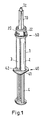
- Fig. 1 shows a discharge device according to the invention for mixing and dispensing of multi-component masses according to a preferred embodiment.
- the Fig. 1 formed as a double syringe multi-component cartridge 1 has a container which has two substantially cylindrical and firmly interconnected chambers 2, 3 for receiving different components.
- the components here are the two components of a two-component adhesive, which may only be mixed together shortly before application to the objects to be bonded.
- other components can also be stored in the chambers, for example impression materials for dental applications.
- the present multicomponent cartridge is particularly suitable for all applications in which small amounts of the components are to be applied once.
- the multi-component cartridge has an entrance end 40 and an exit end 50.
- the inlet end 40 contains inlet openings 41, 42, through which the chambers 2, 3 filled with the corresponding components can be.
- the outlet end 50 includes an outlet part 5, which in Fig. 3 is shown.
- the multi-component cartridge has a squeeze-out ram 4, which of Fig. 1 down to the entry end 40 of the multi-component cartridge can be pushed out.
- the push-out ram has for each of the chambers 2, 3 corresponding piston elements, which are displaceable along the inner wall of the chambers. During a movement of these pistons in the direction of the outlet end 50, the components located in the chambers are pushed in the direction of the outlet part 5.
- the outlet part 5 includes discharge openings 9, 29, which in turn Fig. 3 are visible.
- a mixer housing 10 is arranged, which is designed as a discharge tube.
- the mixer housing has according to Fig. 1 a substantially square cross section and a discharge opening 12 for discharging the components mixed on the way through the mixer housing.
- the mixer housing contains a mixing element 30, not shown here, which is described below in connection with FIG Fig. 3 showing the mixer element 30 will be described in more detail.
- the mixer element is integrally connected to the outlet part 5, that is, the mixer element is manufactured in a single step as part of the multi-component cartridge.
- the mixer housing is slipped over mixer element and by an appropriately trained rotary element in a in Fig. 1 kept closed position shown.
- the rotary element of Fig. 1 is designed as a rotary cap 20.
- the rotary cap is rotatable relative to the multi-component cartridge 1 or to the mixer housing 10.
- Fig. 2 shows a section of a view of the multi-component cartridge 1, which the outlet end 50 and a part of the mixer housing 10th shows.
- the exit end 50 is hidden from that of the rotary cap 20.
- the rotary cap 20 is a cup-shaped element which has a bottom with an opening through which the mixer housing 10 can be pushed. At the bottom joins a jacket element, which opens into a free edge region 21. At least one rotary vane 22 is mounted on the jacket element and / or the free edge region 21. By means of the rotary blade 22, it is made easier for the user to make the rotary movement of the rotary cap, or to hold the rotary cap when the mixer housing 10 is to be set in a rotational movement.
- the rotary cap 20 holds the mixer housing 10, wherein the mixer housing 10 has an inlet end which is formed as a collar 11. Of the collar 11, which is largely hidden by the rotary cap 20, only a small part is visible, which is released by the pivot cap slot 24.
- a housing button 14 is arranged on the outer lateral surface of the collar 11.
- the housing button 14 is displaceable in the rotary cap slot 24 by a rotational movement of the mixer housing 10 or the rotary cap 20 along the predetermined by the rotary cap slot 24 line.
- Under housing button is an arbitrarily shaped projection to understand, which has a shape suitable for the rotary cap slot, so that a relative movement of the rotary cap slot and housing button is not hindered.
- the housing button has a width that is smaller than the width of the pivot cap slot.
- a mixing element 30 provided with numerous deflecting elements is provided at an outlet part 5 of the multi-component cartridge 1.
- the mixer element 30 forms a single component with the multicomponent cartridge 1.
- the elongate mixer element 30 has a sleeve over the mixer element 30 can be inverted Mixer housing 10 on.
- the mixer housing 10 and the mixer element 30 are fixed by the rotary cap 20.
- the chambers 2, 3 are channel-shaped to discharge openings 9, 29 extended. Through the discharge openings 9, 29, the components from the chambers 2, 3 can be dispensed into the mixing chamber formed by the attached mixer housing 10, when the mixer housing in the in Fig. 6 shown opened position.
- Each of the discharge openings 9, 29 can be closed by closure elements 16, 26 fixed to the mixer housing 10.
- the closure elements may in particular be designed as sealing plugs.
- the outer surface of the mixer element 30 and the inner wall of the mixer housing 10 have cooperating guide elements, which allow a displacement of the mixer housing 10 on the mixer element 30 only along the longitudinal axis 32 of the mixer element 30.
- the mixer housing 10 is axially displaceably connected to the multi-component cartridge 1 by a connecting element, wherein the multi-component cartridge 1 can be transferred from a closing position closing the dispensing openings 9, 29 into a dispensing position releasing the same.
- the guide elements are designed such that the mixer housing 10 and the mixer element 30 are displaceable against each other in the closing and dispensing position and on the entire path between these two positions only in the axial direction.
- the rotary element 20, the mixer housing 10 and the multicomponent cartridge 1 have a cooperating engagement element 14, 24, which is designed such that by rotating the rotary member 20, an axial relative movement between the mixer housing 10 and Multi-component cartridge 1 results.
- the engagement element is designed in particular as a housing button 14 or as a cap bead.
- the rotary cap 20 is attached to the outlet part 5 or the outer wall of the chambers 2, 3 by means of a snap connection 15.
- the snap connection 15 is located in the region of the free edge region 21 of the rotary cap.
- the free edge region 21 includes on its inside a groove into which an associated projection of the outlet part 5 or the outer wall of the chambers 2, 3 engages.
- the free edge region is elastic, so that by means of a small deflection of the same under application of an axial compressive force a slipping over the outlet part or the outer wall takes place.
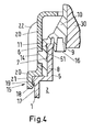
- Fig. 4 is a part of the Fig. 3 which shows the function of the engagement elements 18, 19 and the snap connection 15 in detail.
- the same parts carry the same reference numerals as in Fig. 3 ,
- Fig. 3 a part of the Ausgabehalses 8, which opens into the partially shown discharge opening 9.
- the discharge opening 9 is closed in the present illustration by a sealing plug 16, which is part of the mixer housing 10.
- the mixer housing 10 has a mixer housing collar 11, which is slipped over the dispensing neck. Via a first sealing projection 6 and a second sealing projection 7, the mixer housing 10 is fluid-tightly connected to the dispensing neck 8, so that in the closed state, the component located in the chamber 2 can not escape from the chamber.
- the mixer housing 10 can be displaced in the axial direction, ie substantially in the direction of the longitudinal axis 32 of the mixer element 30, for which purpose the rotary cap 20 is provided.
- the rotary cap 20 has at a free edge region 21 at least partially encircling, annular bead-shaped bulge 18.
- On the outer surface 17 of the multi-component cartridge 1 is a corresponding thereto, at least partially encircling annular Anformung 19 or groove formed, and the free edge portion 21 of the rotary cap 20 for slipping over the bulbous bulge 18 on the annular Anformung 19 or groove of the multi-component cartridge 1 or the mixer housing 10 is elastically deformable.
- the multi-component cartridge that is, in particular the outer wall of the chambers 2, 3 or its outlet part 5 have at the discharge end a locking projection 19, which upon placement of the mixer housing 10 and the rotary cap 20 due to the flexibly formed engaging element, which here as a bulge-shaped bulge 18 of free edge region 21 rotary cap 20 is shown, can be pressed to the outside. After placing the mixer housing 10, the bead-shaped bulge 18 is engaged with the locking projection 19 and thus prevents its removal.
- the inside of the mixer housing collar 11 has two substantially annular closure elements 16, 26 which taper inwards towards the discharge side and have a frustoconical cross section. Due to their special shape, the closure elements 16, 26 make it possible to close the dispensing openings 9, 29, whereby a certain force must be overcome for pulling out the closure elements 16, 26 from the dispensing openings 9, 29, which ensures the tightness in the closed state.
- the guidance of the mixer housing 10 is ensured on the mixer element 30 by their matched square inner or outer contour, the cross-section of both the mixer element 30 and the mixer housing 10 is thus substantially square. So that the components are pressed as completely as possible by the mixer element 30, the distance between the inner contour of the mixer housing 10 and the outer contour of the mixer element 30 is as small as possible, wherein the displacement of the mixer housing 10 must still be possible.
- erroneous placement of the mixer housing 10 on the mixer element 30 can be prevented by means of a coding means that is easily recognizable from the outside, such as, for example, an elliptical shape of the mixer housing collar 11 and the dispensing neck 8 of the multicomponent cartridge 1. Since the mixer element 30 consists of a dimensionally stable material, secure guidance of the mixer housing 10 in the axial longitudinal direction of the multicomponent cartridge is ensured.
- the outer contour of the mixer element 30 and the inner contour of the mixer housing 10 are rectangular, thus have a substantially rectangular cross-section, so that already hereby a rotation-safe guidance of the mixer housing 10 is ensured.
- the mixer housing 10 can be placed on the mixer element 30 exclusively in the position necessary for the secure sealing and engagement of the closure elements 16, 26 in the dispensing openings 9, 29.
- the mixer housing collar 11 of the mixer housing 10 and the output neck 8 of the multi-component cartridge 1 may also have other shapes with a different cross-section, for example circular. Nevertheless, the special shape of the mixer element 30 ensures that the dispensing openings 9, 29 and the closure elements 16, 26 always intermesh.
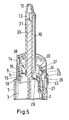
- Fig. 5 shows a variant which shows another mixer element 30, a modified rotary cap 20 and an alternative embodiment of the closure elements 16, 26.
- the guide elements for the axial displacement of the mixer housing 10 on the mixer element 30 are formed by a formQueryähnliche formation of the inner wall 13 of the mixer housing 10 and the outer wall 31 of the mixer element 30, wherein at least the outer wall 31 of the mixer element 30 and the mixer element 30 enclosing inner wall 13 of the mixer housing 10 each have a polygonal, in particular rectangular or elliptical cross-section.
- the discharge device is shown in the open state, so that the filling material, which is a mixture of the located in the chambers 2, 3 components, can be discharged through the discharge opening 12 of the mixer housing 10.
- the housing button 14 is mounted in this variant not on the mixer housing collar 11, but on a projection 37, which in a corresponding Drehkappenschlitz 24 intervenes.
- the extension 37 extends from a closure element 16, 26 carrying connector 38 of the mixer housing.
- the closure elements 16, 26 are arranged on the side facing the cartridge 1.
- the closure elements 16, 26 have a cross-sectional area which is greater in the closed state than in the opened state. In the open state, the corresponding component can flow past the corresponding closure element.
- the closure elements have a spherical shape.
- Fig. 6 shows a schematic view of the mounted on the multi-component cartridge 1 mixer housing 10 without Twist cap.
- the engagement element is visible, which is designed as a housing button 14.
- a plurality of housing buttons may be mounted on the outer surface of the mixer housing collar 11.
- two housing buttons 14 are shown, which are arranged opposite to each other.
- the projection 37 is shown as a cylindrical annular element which extends from the connecting piece 38 in the direction of the mixer housing 10.
- Fig. 7 shows the view Fig. 6 with attached rotary cap in closed position.
- the in Fig. 5 shown closure elements 16, 26 in the corresponding output openings 9, 29 a.
- the housing button 14 is then in the position in which it is the multi-component cartridge 1 closest, so in the illustration of Fig. 7 at the lower end of the pivot cap slot 24.
- the rotary cap has a corrugation 23 on its outer lateral surface.
- rotary vane instead of the same could also rotary vane according to the embodiment according to Fig. 1 to Fig. 4 be provided.
- Fig. 8 shows a second embodiment of a discharge device, for which in turn like-acting parts are to be designated the same. In the following, only the differences to the first embodiment will be discussed, otherwise referred to the first embodiment.
- Fig. 9 shows a detail of the mixer housing and the rotary cap for the second embodiment.
- the mixer housing 10 has the shape of an im substantially cylindrical tube whose cross-section is substantially circular or elliptical.
- the mixer housing 10 has a guide element 33, along which it is displaceable relative to the mixer element 30 in the direction of the common longitudinal axis 32.
- Fig. 10 shows a detail of the rotary cap 20 of the second embodiment.
- the rotary cap 20 is configured with a rotary wing 22 and is as in Fig. 1 to 4 show a cup-shaped element, which has a bottom 60, a jacket element 61 and a free edge region 21.
- the jacket member 61 includes as in Fig. 2 a pivot cap slot 24, however, unlike the first embodiment, the pivot cap slot includes an extension formed as a slot member 64.
- This slot member 64 forms with the housing button a bayonet protection.
- the slot member 64 extends over a portion of the circumference of the shell member 61 and is disposed in a normal plane to the longitudinal axis of the pivot cap 20.
- Fig. 11 is a section through the mixer housing according to the second embodiment.
- the mixer element 30 is received in a groove 34 of the guide element 33 of the mixer housing 10. It is also possible to provide a plurality of such grooves 34; in particular, a first groove 34 and a second groove 35 can be provided, which are arranged mirror-symmetrically with respect to one another.
- the plane of symmetry according to this embodiment runs along the longitudinal axis 32 of the mixer element 30 and is aligned normal to the center wall 36 of the mixer element.
- Fig. 12 shows a variant of the second embodiment of a mixer element with a square cross-section.
- the rotary cap slot 24 has a slot element 64 which forms a bayonet securing device with the housing button.
- the rotary member 20 is rotatable, but fixed in the axial direction fixed to the multi-component cartridge 1, wherein the rotary member 20 is fixed by means of a snap-lock connection 15 on the multi-component cartridge 1 or on the mixer housing 10.
- Fig. 13 shows a third embodiment of a discharge device, according to which the rotary cap 20 is fixed with a bayonet securing to the multi-component cartridge 1, wherein the bayonet protection differs from those of the preceding embodiments.
- At at least one end of the rotary cap slot 24 in a normal plane to the longitudinal axis of the rotary cap 20 joins another slot member which forms a bayonet lock together with the guide element.
- Fig. 14 shows a part of the mixer housing 10 and the rotary cap 20 for the third embodiment.
- the bayonet lock is in Fig. 14 shown in detail.
- the rotary cap 20 has a Drehkappenschlitz 24 and another slot member 70 which is associated with the bayonet protection. Furthermore, the rotary cap on a flange 71, which also contains a part of the bayonet protection.
- Fig. 15 shows a section through the rotary cap of the third embodiment and Fig. 16 a detail of the flange 70 with the bayonet protection.
- the mixer element 30 is formed integrally with the cartridge 1.
- the cartridge 1 contains the two chambers 2, 3, which open into outlet part 5, each containing an outlet channel which leads to the corresponding outlet opening 9, 29 and forms a channel through which the corresponding component flows whose cross-sectional area is generally smaller than the cross-sectional area the corresponding chamber.
- the mixer housing 10 is slipped over the mixer element 30 and placed on the outlet part of the cartridge such that the sealing plugs 16, 26 close the corresponding outlet openings 9, 29.
- On the outer wall of the output neck 8 of the outlet part 5 are as in Fig. 4 a first seal protrusion 6 and a second seal protrusion 7 arranged. In this position, the chambers 2, 3 are sealed fluid-tight, so that an exit of the components from the discharge openings 9, 29 can not be done.
- the rotary cap 20 is passed over the mixer housing 10 and the mixer housing collar 11 until it rests on the flange 71.
- the rotary cap has on its outer surface 61, a slot member 70 for each housing button 14, so that the rotary cap 20 can be slipped over the mixer housing collar.
- the rotary cap is placed in a predetermined position relative to the cartridge 1 on the flange 71, said predetermined position is determined by the slot member 70.
- Fig. 16 which is a detail of Fig. 15 shows, the slot member is shown in the position in which the rotary cap can be guided via the housing button 14.
- an extension 72 is provided, which allows the rotary cap on the housing button 14 along the inner wall of the extension 72 can be passed over.
- Fig. 15 is shown on the right side, the lateral surface 61 contains instead of an extension a recess 73. According to this variant, no change in the inner diameter of the lateral surface of the rotary cap, as in the left side shown variant of the extension 72, which incidentally also in Fig. 14 is visible.
- the rotary cap is rotated in the direction of the pivot cap slot 24 so that the housing button 14 can be displaced along the path defined by the pivot cap slot 24.
- the direction of rotation is in the in Fig. 5 shown left-side embodiment and in Fig. 14 predetermined by a stop 74.
- the discharge openings 9, 29 are opened when the housing button 14 is in the highest position (see Fig. 14 ) is located in the pivot cap slot 24. In this position, the components can enter the mixer element 30 through the opened discharge openings 9, 29 and the discharge of the components from the chambers of the cartridge can take place.
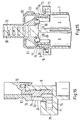
- Fig. 17 shows a fourth embodiment of a discharge device, according to which the rotary cap has a pivot cap slot, which allows two different open positions.
- Fig. 18 shows a detail of the mixer housing and the rotary cap for the fourth embodiment.
- the rotary cap has, following the lateral surface 61, a further lateral surface 62, which has a larger inner diameter than the lateral surface 61.
- the lateral surface 61 is connected to the lateral surface 62 via a shoulder 63.
- the lateral surface 62 includes a pivot cap slot 84 along which a button member 85 is slidable along a path defined by the pivot cap slot 84.
- the mixer housing 10 is guided over the mixer element 30 and placed on the output neck 8 of the cartridge. Thereafter, the rotary cap 20 is moved over the mixer housing 10 in the direction of the outlet end 50 of the cartridge 1.
- the rotary cap contains in the lateral surface 62 a bulge 86 through which the button element 85 can be passed.
- the rotating cap is in the representation according to Fig. 18 shifted down until the button member 85 is present at the upper end of the pivot cap slot 84. In this state, the discharge openings of the cartridge 1 are closed.
- the rotary cap In order to discharge the components from the cartridge, the rotary cap is now turned either to the left or to the right.
- the button member 85 slides along the path defined by the pivot cap slot 84 so that the mixer housing 10 is displaced so as to release the discharge openings.
- Fig. 19 shows a section through the rotary cap 20 according to the fourth embodiment along the rotary blades 22 in the in Fig. 18 drawn position in which the discharge openings 9, 29 are closed by the closure elements 16, 26.
- the mixer housing 10 also has a mixer housing collar 11, but unlike the previous embodiments, a rotating mixer housing flange 88.
- the mixer housing flange 88 engages a circumferential Drehkappennut 86, so that the rotary cap relative to the mixer housing 10 rotatable, but not relative to the mixer housing 10th axially displaceable, which is especially in Fig. 20 which is a detail of the mixer housing and the rotary cap for the embodiment according to Fig. 19 shows.
- the button member 85 is attached to the wall of the cartridge 1.
- the rotary member 20 has a helically extending in the longitudinal direction of the mixer element 30 Drehkappenschlitz 24 and the mixer housing 10 cooperating with the Drehkappenschlitz 24 guide element.
- the mixer housing 10 may have on its outer surface 25 a helical in the longitudinal direction of the mixer element 30 extending housing groove and the rotary cap 20 cooperating with the housing groove guide member.
- the pivot cap slot 24 or the housing groove are in particular designed such that the rotation of the rotary cap 20 about the longitudinal axis of the mixer element 30 from the closed position to the dispensing position 270 ° and less, in particular 90 ° to 180 °, based on a full circle of 360 °.
- the outer surface 51 of the outlet part 5 and / or the inner wall 13 of the mixer housing 10 may have a sealing means 6, 7, during the expression of the components to be mixed from the chambers 2, 3 a leaking leakage of the components between the mixer housing 10 and the multi-component cartridge. 1 to prevent.
- the mixer housing according to each of the preceding embodiments may be transparent or translucent. This allows a visual check that gives mixer satisfactory results, especially when blending differently colored components.
- the mixer housing can also be opaque, especially if polypropylene or polystyrene are used as materials.
Abstract
Description
Die Erfindung betrifft eine Austragsvorrichtung zum Mischen und Ausbringen von Mehrkomponentenmassen nach dem Oberbegriff des Anspruchs 1.The invention relates to a discharge device for mixing and discharging multicomponent masses according to the preamble of
Eine Vorrichtung zum Mischen und Ausbringen von Mehrkomponentenmassen wird in
Durch die Möglichkeit der Drehung des Austragsrohrs in eine geeignete Austragsstellung und die damit verbundene Verwendung einer flexiblen Mischwendel wird das Aufsetzen der Kappe mit dem Austragsrohr über die Mischwendel erschwert. Zudem ist die Struktur der Mischwendel empfindlich auf mechanische Beschädigungen, so dass die empfindliche flexible Mischerstruktur vorsichtig in das Austragsrohr eingesetzt werden muss, wobei gleichzeitig auf den richtigen Sitz der Kappe auf dem zylinderförmigen Vorsprung geachtet werden muss. Auch das Verschieben der Kappe zwischen der geöffneten und der geschlossenen Stellung birgt die Gefahr des Verkippens der Kappe und der Beschädigung der Mischwendel.Due to the possibility of rotation of the discharge pipe in a suitable discharge position and the associated use of a flexible mixing spiral, the placement of the cap with the discharge pipe via the mixing spiral is made more difficult. In addition, the structure of the mixing coil is sensitive to mechanical damage, so that the sensitive flexible mixer structure must be carefully inserted into the discharge tube, while at the same time paying attention to the correct seating of the cap on the cylindrical projection. Also, the displacement of the cap between the open and the closed position carries the risk of tilting of the cap and the damage of the mixing helix.
Um das Aufsetzen eines Austragsrohrs auf einer Mehrkomponentenkartusche zu vereinfachen, wird in
Die gattungsgemässe
Die
Die aus dem Stand der Technik bekannten Ausgabevorrichtungen stellen nicht auf einfache Weise sicher, dass das Austragsrohr beim Aufsetzen sauber auf dem Spritzenteil angeordnet werden kann, ohne die Mischwendel zu beschädigen. Auch besteht die Gefahr, dass das Austragsrohr nicht sauber auf dem Spritzenteil aufgesetzt wird, so dass beim Ausdrücken der Spritzen die Komponenten seitlich an den Verbindungsstellen zwischen Spritzenteilen und Austragsrohr austreten können.The dispensing devices known from the prior art do not easily ensure that the dispensing tube can be arranged cleanly on the syringe part during placement without damaging the mixing coil. There is also the risk that the dispensing tube is not placed cleanly on the syringe part, so that when squeezing the syringes, the components can emerge laterally at the connection points between the syringe parts and the dispensing tube.
Aufgabe vorliegender Erfindung ist die Bereitstellung einer einfach aufgebauten Austragsvorrichtung zum Mischen und Ausbringen von Mehrkomponentenmassen, welche ein ungewolltes Ausbringen oder Vermischen der Einzelkomponenten verhindert und ein Hin- und Herbewegen eines Verschlusselementes zwischen einer geöffneten und einer geschlossenen Stellung der Austragsvorrichtung ermöglicht.The object of the present invention is to provide a simply constructed discharge device for mixing and dispensing multicomponent masses, which prevents unintentional dispensing or mixing of the individual components and enables a reciprocating movement of a closure element between an open and a closed position of the dispensing device.
Diese Aufgabe wird durch eine Austragsvorrichtung mit den Merkmalen des Anspruchs 1 gelöst. Vorteilhafte Ausgestaltungen und zweckmäßige Weiterbildungen der Erfindung sind in den Unteransprüchen angegeben.This object is achieved by a discharge device with the features of
Die erfindungsgemässe Austragsvorrichtung zum Mischen und Ausbringen von Mehrkomponentenmassen enthält eine Mehrkomponentenkartusche oder Mehrkomponentenspritze mit mehreren insbesondere zylinderförmigen Kammern, wobei insbesondere Doppelkartuschen oder Doppelspritzen mit zwei Kammern bevorzugt werden. In der Folge wird stellvertretend für sämtliche Ausführungsformen der Begriff Mehrkomponentenkartusche verwendet. Die Kammern, d.h. der Innenraum der Kartuschen, können kreiszylinderförmig ausgebildet sein oder einen elliptischen oder polygonalen Querschnitt aufweisen. Die Kammern enthalten im befüllten Zustand zumindest je eine fluide Komponente einer Füllmasse. Diese Füllmasse ist von der Umgebung in der Regel durch einen frei in der Kammer verschiebbaren Kartuschenkolben getrennt. Der Kartuschenkolben enthält Dichtungselemente, welche den Kammerinhalt fluiddichtend von der Umgebung abschliessen. Die Komponenten in den Kammern der Mehrkomponentenkartusche werden mit Hilfe eines Ausdrückstössels ausgetragen, welcher den entsprechenden Kartuschenkolben derart zusammenwirkt, dass die Kartuschenkolben in der Kammer verschoben werden können.The discharge device according to the invention for mixing and dispensing multicomponent masses contains a multicomponent cartridge or multicomponent syringe with a plurality of, in particular, cylindrical chambers, with double-cartridges or double-syringes having two chambers being particularly preferred. As a result, the term multicomponent cartridge is used as a representative of all embodiments. The chambers, i. the interior of the cartridges may be formed circular-cylindrical or have an elliptical or polygonal cross-section. The chambers contain at least one fluid component of a filling compound in the filled state. This filling material is separated from the environment usually by a freely displaceable in the chamber cartridge piston. The cartridge piston contains sealing elements, which seal the chamber contents fluid-tight from the environment. The components in the chambers of the multicomponent cartridge are discharged by means of an ejector ram, which cooperates with the corresponding cartridge piston such that the cartridge pistons can be displaced in the chamber.
Die Mehrkomponentenkartuschen beinhalten neben den zylinderförmigen Kammern auch eine als Auslassteil dienende Anformung. Dabei betrifft der Auslassteil beispielsweise eine Gesamtheit von rohrförmigen Anformungen der einzelnen Kammern und/oder ein zylindrisches Anschlussteil. Das Auslassteil ist von der Drehkappe übergreifbar und weist mischerseitig für jede Komponente eine Ausgabeöffnung auf, d.h. die einzelnen Komponenten werden bis zum mischerseitigen Ende des Auslassteils voneinander getrennt gehalten, so dass eine vorzeitige Vermischung der Komponenten verhindert wird. Die Ausgabeöffnungen können durch die Drehkappe somit fluiddicht verschlossen gehalten werden, sodass die Komponenten in den Kammern der Mehrkomponentenkartusche über längere Zeiträume gelagert werden können und auch in der Mehrkomponentenkartusche transportiert werden können.The multicomponent cartridges contain, in addition to the cylindrical chambers, an integral part serving as an outlet part. It concerns the Auslassteil example, a total of tubular projections of the individual chambers and / or a cylindrical connection part. The outlet part can be engaged by the rotary cap and, on the mixer side, has an outlet opening for each component, ie the individual components are kept separate from one another up to the mixer-side end of the outlet part, so that premature mixing of the components is prevented. The dispensing openings can thus be kept fluid-tightly closed by the rotary cap, so that the components in the chambers of the multi-component cartridge can be stored for longer periods and can also be transported in the multi-component cartridge.
Die Austragsvorrichtung weist auch ein an der Mehrkomponentenkartusche angeformtes und damit festgelegtes, längliches Mischerelement auf und ein über das Mischerelement stülpbares Mischergehäuse. Unter festgelegtem Mischerelement wird ein mit der Mehrkomponentenkartusche einstückig verbundenes Mischerelement verstanden, das heisst Mehrkomponentenkartusche und Mischerelement bilden ein einziges Bauteil.The discharge device also has an elongate mixing element integrally formed on the multi-component cartridge and thus fixed, and a mixer housing which can be turned over the mixer element. A fixed mixer element is understood as meaning a mixer element which is integrally connected to the multicomponent cartridge, that is to say a multicomponent cartridge and mixer element form a single component.
Jede Kammer der Mehrkomponentenkartusche weist eine Ausgabeöffnung auf, welche durch am Mischergehäuse festgelegte Verschlusselemente verschliessbar sind, wobei die Aussenfläche des Mischerelements und die Innenwand des Mischergehäuses ein zusammenwirkendes Führungselement aufweisen, welches eine Verschiebung des Mischergehäuses auf dem Mischerelement nur entlang der Längsachse des Mischerelements erlaubt. Das Mischergehäuse ist durch ein Verbindungselement mit der Mehrkomponentenkartusche axial verschiebbar verbunden. Die Mehrkomponentenkartusche ist von einer die Ausgabeöffnungen verschliessenden Schliessstellung in eine dieselben freigebende Ausgabestellung überführbar.Each chamber of the multi-component cartridge has an outlet opening which can be closed by closure elements fixed to the mixer housing, wherein the outer surface of the mixer element and the inner wall of the mixer housing have a cooperating guide element which allows a displacement of the mixer housing on the mixer element only along the longitudinal axis of the mixer element. The mixer housing is connected by a connecting element with the multi-component cartridge axially displaceable. The multi-component cartridge can be transferred from a closing position closing the dispensing openings into a dispensing position which releases the dispensing openings.
Das Führungselement ist insbesondere derart ausgebildet, dass das Mischergehäuse und das Mischerelement in der Schliess- und Ausgabestellung sowie auf dem gesamten Weg zwischen diesen beiden Stellungen nur in axialer Richtung gegeneinander verschiebbar sind. Das Verbindungselement ist ein Drehelement, wobei das Drehelement, das Mischergehäuse und die Mehrkomponentenkartusche ein kooperierendes Eingriffselement aufweisen, das derart ausgebildet ist, dass durch Drehen des Drehelements eine axiale Relativbewegung zwischen Mischergehäuse und Mehrkomponentenkartusche resultiert.The guide element is in particular designed such that the mixer housing and the mixer element in the closing and dispensing position and on the entire path between these two positions are only mutually displaceable in the axial direction. The connecting element is a rotary element, wherein the rotary element, the mixer housing and the multi-component cartridge have a cooperating engagement element, which is designed such that by rotating the rotary element results in an axial relative movement between the mixer housing and multi-component cartridge.
Bevorzugt ist das Mischerelement und die Mehrkomponentenkartusche einstückig ausgebildet, wobei dann das Mischerelement und die Mehrkomponentenkartusche aus demselben Werkstoff bestehen. Dabei bildet das Mischerelement eine Anformung an das Auslassteil der Mehrkomponentenkartusche, wobei das Mischerelement zweckmässigerweise zwischen den Ausgabeöffnungen der Kartuschen liegt. Das Mischerelement ist bevorzugt formstabil ausgebildet und weist zumindest bei Raumtemperatur eine starre Form auf, sodass es starr von der Mehrkomponentenkartusche abragt. Das Mischerelement ist zweckmässigerweise ein zylinderförmiges oder kegelstumpfförmiges Element mit einem elliptischen oder polygonalen Querschnitt. Bevorzugt ist das Mischerelement zylindrisch ausgebildet und weist einen rechteckförmigen Querschnitt auf. Diese besondere Ausführungsform hat den Vorteil, dass beim Zusammenbau von Mischerelement und Mischergehäuse ein fehlerhaftes Aufsetzen des Mischergehäuses auf dem Mischerelement ausgschlossen ist. Weiter bevorzugt weist dabei das Mischerelement zwei längliche geschlossene Mischerwände auf, wobei die beiden anderen Mischer-Längswände offen ausgebildet sind.Preferably, the mixer element and the multi-component cartridge is integrally formed, in which case the mixer element and the multicomponent cartridge consist of the same material. In this case, the mixer element forms a molding on the outlet part of the multi-component cartridge, wherein the mixer element is conveniently located between the discharge openings of the cartridges. The mixer element is preferably dimensionally stable and has a rigid shape, at least at room temperature, so that it protrudes rigidly from the multicomponent cartridge. The mixer element is expediently a cylindrical or frustoconical element with an elliptical or polygonal cross section. Preferably, the mixer element is cylindrical and has a rectangular cross-section. This particular embodiment has the advantage that when assembling mixer element and mixer housing a faulty placement of the mixer housing is dispensed on the mixer element. More preferably, the mixer element has two elongate closed mixer walls, wherein the other two mixer longitudinal walls are open.
Das Mischerelement weist eine Längsmittelachse auf, welche im Weiteren auch als Längsachse bezeichnet wird. Die Längsmittelachsen der Kammern der Mehrkomponentenkartusche liegen bevorzugt alle parallel zueinander. Ganz bevorzugt ist die Austragsvorrichtung derart aufgebaut, dass die Längsmittelachsen der Kammern und die Längsachse des Mischerelements alle parallel zueinander liegen. Im Weiteren wird unter axialer Richtung der Austragsvorrichtung immer die Richtung der Längsachse des Mischerelements verstanden.The mixer element has a longitudinal central axis, which is also referred to below as the longitudinal axis. The longitudinal central axes of the chambers of the multicomponent cartridge are preferably all parallel to one another. Most preferably, the discharge device is constructed such that the longitudinal center axes of the chambers and the longitudinal axis of the mixer element are all parallel to each other. Furthermore, in the axial direction of the discharge device, the direction of the longitudinal axis of the mixer element is always understood.
Die Austragsvorrichtung weist auch ein über das Mischerelement stülpbares Mischergehäuse auf. Das Mischergehäuse weist an dem Auslassteil der Mehrkomponentenkartusche gegenüberliegenden Ende einen bevorzugt konisch sich verjüngenden Auslassbereich mit einer Austragsöffnung auf. Am kartuschenseitigen Ende weist das Mischergehäuse ein Verschlusselement zum Verschliessen zumindest einer der Ausgabeöffnungen der Kammern auf. Als Verschlusselement werden an das Mischergehäuse festgelegte Verschlussstopfen bevorzugt. Die Verschlussstopfen sind insbesondere als an das Mischergehäuse angeformte Verschlusselemente ausgebildet. Demnach sind die Verschlussstopfen und das Mischergehäuse bevorzugt einstückig aus demselben Material ausgebildet.The discharge device also has a mixer housing which can be turned over via the mixer element. The mixer housing has at the end opposite the outlet part of the multicomponent cartridge a preferably conically tapered outlet region with a discharge opening. At the cartridge-side end, the mixer housing has a closure element for closing at least one of the dispensing openings of the chambers. As closure element, sealing plugs fixed to the mixer housing are preferred. The sealing plugs are designed, in particular, as closure elements formed on the mixer housing. Accordingly, the sealing plug and the mixer housing are preferably integrally formed from the same material.
Die Mehrkomponentenkartusche, das Mischerelement und das Mischergehäuse bestehen bevorzugt aus demselben Werkstoff. Als Werkstoff eignet sich insbesondere Kunststoff, wobei alle Kunststoffe, welche zu formstabilen, im Wesentlichen starren Strukturen verarbeitet werden können, verwendet werden können. Speziell bevorzugt werden Polypropylen (PP), Polyoximethylen (POM) und Acrylnitril-Butadien-Styren Copolymerisat (ABS). In einer ersten Ausführungsform der erfindungsgemässen Austragsvorrichtung weist der das Mischerelement umfassende Innenraum des Mischergehäuses eine zum Mischerelement passgenaue Form auf, wobei ein minimales Spiel zur Gewährleistung einer axialen Verschiebung des Mischergehäuses auf dem Mischerelement vorhanden ist. Hierbei bilden die formschlussähnliche Ausbildung der Innenwand des Mischergehäuses und der Aussenwand des Mischerelements die erforderlichen axialen Führungselement, um sicherzustellen, dass die Verschiebung des Mischergehäuses auf dem Mischerelement nur entlang der Längsachse des Mischerelements möglich ist.The multi-component cartridge, the mixer element and the mixer housing are preferably made of the same material. In particular plastic is suitable as the material, wherein all plastics which can be processed into dimensionally stable, substantially rigid structures can be used. Especially preferred are polypropylene (PP), polyoxymethylene (POM) and acrylonitrile-butadiene-styrene copolymer (ABS). In a first embodiment of the discharge device according to the invention, the interior of the mixer housing comprising the mixer element has a shape which fits precisely to the mixer element, wherein a minimal clearance is provided to ensure axial displacement of the mixer housing on the mixer element. In this case, the form-fitting-like design of the inner wall of the mixer housing and the outer wall of the mixer element form the required axial guide element to ensure that the displacement of the mixer housing on the mixer element is possible only along the longitudinal axis of the mixer element.
In einer weiteren Ausführungsform der erfindungsgemässen Austragsvorrichtung werden die Führungselement zur axialen Verschiebung des Mischergehäuses auf dem Mischerelement nicht durch einen Formschluss des Mischerelements mit dem Mischergehäuse gebildet, sondern durch wenigstens eine in axialer Richtung verlaufende Nut-Feder-Anordnung. Dabei kann nur eine einzige axial verlaufende Nut-Feder-Anordnung verwendet werden, oder aber auch eine Mehrzahl getrennt angeordneter, axial verlaufender Nut-Feder-Anordnungen. Die Nut kann sich jeweils im Mischerelement befinden, wobei dann eine federförmige Anformung am Mischergehäuse notwendig ist, oder die Nut kann an der Innenseite des Mischergehäuses angebracht sein, wobei in diesem zweiten Fall dann eine federförmige Anformung an der Aussenwand des Mischerelements erforderlich ist.In a further embodiment of the inventive discharge device, the guide element for axial displacement of the mixer housing on the mixer element are not formed by a positive connection of the mixer element with the mixer housing, but by at least one extending in the axial direction tongue and groove arrangement. In this case, only a single axially extending tongue and groove arrangement can be used, or else a plurality of separately arranged, axially extending tongue and groove arrangements. The groove can each be in the mixer element, in which case a spring-shaped molding on the mixer housing is necessary, or the groove can be attached to the inside of the mixer housing, in which case a spring-shaped Anformung on the outer wall of the mixer element is required.
Das Mischergehäuse ist durch ein Verbindungselement mit der Mehrkomponentenkartusche axial verschiebbar verbunden. Wesentlich dabei ist, dass das Mischergehäuse mit den angeformten Verschlussstopfen für die Ausgabeöffnungen der Kammern von einer die Ausgabeöffnungen verschliessenden Schliessstellung in eine dieselben freigebende Ausgabestellung bewegbar ist. Weiter erfindungswesentlich ist, dass die axialen Führungselement derart ausgebildet sind, daß das Mischergehäuse und das Mischerelement in der Schliess- und Ausgabestellung sowie auf dem gesamten Weg zwischen diesen beiden Stellungen nur in axialer Richtung gegeneinander verschiebbar sind.The mixer housing is connected by a connecting element with the multi-component cartridge axially displaceable. It is essential that the mixer housing with the molded sealing plug for the discharge openings of the chambers is movable from a closing position closing the discharge openings into a dispensing position which releases them. Next essential to the invention is that the axial guide element are formed such that the mixer housing and the mixer element in the closing and dispensing position and on the the entire path between these two positions are only mutually displaceable in the axial direction.
Das die Mehrkomponentenkartusche mit dem Mischergehäuse verbindende Drehelement ist insbesondere eine Drehkappe, die entweder relativ zu der Mehrkomponentenkartusche oder dem Mischergehäuse drehbar ist, aber in axialer Richtung ortsfest befestigt ist. Die Drehkappe ist ein becherförmiges Element mit einem Deckel mit einer mittig angeordneten Ausnehmung zur Durchführung des Mischergehäuses und einer umlaufenden Wand. Der Deckel hat insbesondere eine im Wesentlichen rotationssymmetrische Form. Die umlaufende Wand weist insbesondere einen freiliegenden Randbereich auf.The rotary element connecting the multicomponent cartridge to the mixer housing is, in particular, a rotary cap which is rotatable either relative to the multicomponent cartridge or the mixer housing, but is fixed in the axial direction in a stationary manner. The rotary cap is a cup-shaped element with a lid with a centrally located recess for the passage of the mixer housing and a peripheral wall. In particular, the lid has a substantially rotationally symmetrical shape. The circumferential wall has, in particular, an exposed edge area.
Nach einem alternativen Ausführungsbeispiel kann das Drehelement eine Schrauben-Mutter sein und das Mischergehäuse oder die Mehrkomponentenkartusche eine damit kooperierende Windung aufweisen.In an alternative embodiment, the rotary member may be a screw nut and the mixer housing or multi-component cartridge may have a coil cooperating therewith.
Das Befestigen des Drehelements, also insbesondere der Drehkappe an der Mehrkomponentenkartusche oder am Mischergehäuse geschieht beispielsweise durch eine Schnapp-Rast-Verbindung oder durch eine Bajonettverbindung.The fastening of the rotary member, so in particular the rotary cap on the multi-component cartridge or on the mixer housing is done for example by a snap-lock connection or by a bayonet connection.
Eine Schnapp-Rast-Verbindung wird vorzugsweise dadurch gebildet, dass die Drehkappe an einem freien Randbereich eine wenigstens teilweise umlaufende, ringförmige wulstförmige Ausbuchtung aufweist und an der Aussenfläche der Mehrkomponentenkartusche oder an der Aussenfläche des Mischergehäuses eine mit der wulstförmigen Ausbuchtung kooperierende, wenigstens teilweise umlaufende ringförmige Anformung oder Nut ausgebildet ist.A snap-lock connection is preferably formed in that the rotary cap has an at least partially encircling annular bead-shaped bulge on a free edge region and on the outer surface of the multi-component cartridge or on the outer surface of the mixer housing a cooperating with the bead-shaped bulge, at least partially encircling annular Anformung or groove is formed.
Bei der Aussenfläche handelt es sich insbesondere um die Aussenfläche des Auslassteils.The outer surface is in particular the outer surface of the outlet part.
Der freie Randbereich der Drehkappe ist zum Überstülpen der wulstförmigen Ausbuchtung über die ringförmige Anformung oder Nut am Auslassteil der Mehrkomponentenkartusche oder des Mischergehäuses elastisch verformbar ausgebildet.The free edge region of the rotary cap is formed to slipping over the bead-shaped bulge on the annular Anformung or groove on the outlet part of the multi-component cartridge or the mixer housing elastically deformable.
Die Drehkappe kann in der Schliessstellung und/oder in der Ausgabestellung der Mehrkomponentenkartusche festlegbar sein, insbesondere mittels eines Bajonettverschlusses.The rotary cap can be fixed in the closed position and / or in the dispensing position of the multicomponent cartridge, in particular by means of a bayonet closure.
Nach einem vorteilhaften Ausführungsbeispiel weist die Drehkappe einen schraubenförmig in Längsrichtung des Mischerelements verlaufenden Drehkappenschlitz und das Mischergehäuse ein mit dem Drehkappenschlitz kooperierendes Führungselement, insbesondere einen Gehäuseknopf, auf. Nach einer vorteilhaften Variante schliesst wenigstens an einem Ende des Drehkappenschlitzes in einer Normalebene zur Längsachse der Drehkappe ein weiteres Schlitzelement an, welches zusammen mit dem Führungselement eine Bajonettsicherung bildet.According to an advantageous embodiment, the rotary cap has a rotary cap slot extending helically in the longitudinal direction of the mixer element, and the mixer housing has a guide element cooperating with the rotary cap slot, in particular a housing button. According to an advantageous variant, a further slot element adjoins at least at one end of the rotary cap slot in a normal plane to the longitudinal axis of the rotary cap, which together with the guide element forms a bayonet securing device.
Nach einem weiteren vorteilhaften Ausführungsbeispiel weist das Mischergehäuse an seiner Aussenfläche eine schraubenförmig in Längsrichtung des Mischerelements verlaufende Gehäusenut und die Drehkappe ein mit der Gehäusenut kooperierendes Führungselement, insbesondere einen Drehkappenknopf, auf.According to a further advantageous embodiment, the mixer housing has on its outer surface a helical in the longitudinal direction of the mixer element extending housing groove and the rotary cap cooperating with the housing groove guide element, in particular a rotary cap knob on.
Nach einer weiteren vorteilhaften Variante schliesst sich an wenigstens einem Ende der Gehäusenut in einer Normalebene zur Längsachse des Mischergehäuses ein weiteres Nutelement an, welches zusammen mit dem Führungselement eine Bajonettsicherung bildet.According to a further advantageous variant, a further groove element adjoins at least one end of the housing groove in a normal plane to the longitudinal axis of the mixer housing, which groove forms a bayonet lock together with the guide element.
Der Drehkappenschlitz oder die Gehäusenut sind Vorteilhafterweise derart ausgebildet, daß die Drehung der Drehkappe um die Längsachse des Mischerelements von der Schliessstellung zur Ausgabestellung 270° und weniger, insbesondere 90° bis 180°, bezogen auf einen Vollkreis von 360°, beträgt.The Drehkappenschlitz or the housing groove are advantageously designed such that the rotation of the rotary cap about the longitudinal axis of the mixer element from the closed position to the dispensing position 270 ° and less, in particular 90 ° to 180 °, based on a full circle of 360 °.
Die axiale Relativbewegung zwischen Mischergehäuse und Mehrkomponentenkartusche von der Schliessstellung zur Ausgabestellung beträgt vorzugsweise 0.5 mm bis 4 mm, insbesondere 1 mm bis 3 mm.The axial relative movement between mixer housing and multi-component cartridge from the closed position to the dispensing position is preferably 0.5 mm to 4 mm, in particular 1 mm to 3 mm.
Die Aussenfläche der Drehkappe kann axial verlaufende Drehflügel oder eine über den Umfang verteilte, axial verlaufende Riffelung zur verbesserten manuellen Drehmomentübertragung aufweisen.The outer surface of the rotary cap may have axially extending rotary vanes or circumferentially distributed, axially extending corrugations for improved manual torque transmission.
Insbesondere weisen das Mischerelement und das Mischergehäuse kooperierende Codiermittel auf, sodass das Mischergehäuse nur in einer vorgegebenen Stellung auf das Mischerelement aufgesetzt werden kann. Die Mehrkomponentenkartusche weist am mischerseitigen Ende ein Auslassteil auf, der vom Mischergehäuse übergreifbar ausgebildet ist und die Aussenfläche des Auslassteils und/oder die Innenwand des Mischergehäuses weisen Dichtungsmittel auf, um während des Ausdrückens der zu vermischenden Komponenten aus den Kammern ein leckhaftes Austreten der Komponenten zwischen dem Mischergehäuse und der Mehrkomponentenkartusche zu verhindern.In particular, the mixer element and the mixer housing have cooperating coding means, so that the mixer housing can be placed on the mixer element only in a predetermined position. The multicomponent cartridge has at the mixer-side end an outlet part, which is designed to be engaged by the mixer housing and the outer surface of the outlet part and / or the inner wall of the mixer housing have sealing means in order to eject the components to be mixed from the chambers a leaking leakage of the components between the Mixer housing and the multi-component cartridge to prevent.
Bei der erfindungsgemässen Mehrkomponentenkartusche kann nach einem vorteilhaften Ausführungsbeispiel das Mischerelement als Führungselement zur axialen Verschiebung des Mischergehäuses ausgebildet sein um das Aufsetzen und Verschieben des Mischergehäuses auf dem Auslassteil der Mehrkomponentenkartusche zu ermöglichen. Um eine Fixierung des Mischergehäuses in einer geöffneten Stellung und/oder in einer geschlossenen Stellung des Mischergehäuses sicherzustellen, können in einer vorteilhaften Ausführung der Erfindung am Auslassteil und/oder an der Aussenwand der Kammern und/oder dem Mischergehäuse zusätzliche Eingriffselemente, insbesondere Rastnasen und korrespondierende Rastnuten, vorgesehen sein. Hierdurch können einerseits die Komponenten störungsfrei ausgegeben werden, andererseits aber die Kammern abdichtend verschlossen werden, wodurch ein Austrocknen oder frühzeitiges Aushärten der in den Kammern vorhandenen Komponenten verhindert werden kann. Besonders vorteilhaft können Ausgabeöffnungen der Kammern durch an dem Mischergehäuse angeordnete korrespondierende Dichtelemente abdichtend verschlossen werden. Zudem helfen die Rastnasen und -nuten dem Anwender sicherzustellen, dass sich das Mischergehäuse in der richtigen Position befindet.In the multi-component cartridge according to the invention, according to an advantageous embodiment, the mixer element can be designed as a guide element for the axial displacement of the mixer housing in order to enable the mixer housing to be placed and moved on the outlet part of the multicomponent cartridge. To fix the To ensure mixer housing in an open position and / or in a closed position of the mixer housing, in an advantageous embodiment of the invention at the outlet part and / or on the outer wall of the chambers and / or the mixer housing additional engagement elements, in particular locking lugs and corresponding locking grooves may be provided. As a result, on the one hand, the components can be output trouble-free, but on the other hand, the chambers are sealingly closed, whereby dehydration or premature curing of the components present in the chambers can be prevented. Particularly advantageous dispensing openings of the chambers can be sealingly closed by arranged on the mixer housing corresponding sealing elements. In addition, the detents and grooves help the user ensure that the mixer housing is in the correct position.
Weitere Besonderheiten und Vorzüge der Erfindung ergeben sich aus der folgenden Beschreibung eines bevorzugten Ausführungsbeispiels anhand der Zeichnungen. Es zeigen
- Fig. 1
- eine dreidimensionale Ansicht einer Mehrkomponentenkartusche mit aufgesetztem Mischergehäuse und Ausdrückstössel;
- Fig. 2
- eine Ansicht eines Ausschnitts der Mehrkomponentenkartusche aus
Fig. 1 ; - Fig. 3
- einen Querschnitt durch das austragseitige Ende der Mehrkomponentenkartusche aus
Fig. 1 ; - Fig. 4
- eine Detailansicht der Verbindung der Drehkappe mit dem Mischergehäuse und dem Ausgabehals gemäss
Fig. 4 ; - Fig. 5
- eine dreidimensionale Ansicht einer Variante des austragseitigen Endes der Mehrkomponentenkartusche sowie der Drehkappe und des Mischergehäuses;
- Fig. 6
- eine schematische Ansicht des aufgesetzten Mischergehäuses ohne Drehkappe;
- Fig. 7
- die Ansicht aus
Fig. 6 mit aufgesetzter Drehkappe in geschlossener Stellung; - Fig. 8
- ein zweites Ausführungsbeispiel einer Austragsvorrichtung;
- Fig. 9
- ein Detail des Mischergehäuses und der Drehkappe für das zweite Ausführungsbeispiel;
- Fig. 10
- ein Detail der Drehkappe des zweiten Ausführungsbeispiels;
- Fig. 11
- einen Schnitt durch das Mischergehäuse gemäss des zweiten Ausführungsbeispiels;
- Fig. 12
- eine Variante des zweiten Ausführungsbeispiels für ein Mischerelement mit einem quadratischen Querschnitt;
- Fig. 13
- ein drittes Ausführungsbeispiel einer Austragsvorrichtung;
- Fig. 14
- ein Detail des Mischergehäuses und der Drehkappe für das dritte Ausführungsbeispiel;
- Fig. 15
- ein Detail der Drehkappe des dritten Ausführungsbeispiels;
- Fig. 16
- einen Schnitt durch das Mischergehäuse gemäss des vierten Ausführungsbeispiels;
- Fig. 17
- ein viertes Ausführungsbeispiel einer Austragsvorrichtung;
- Fig. 18
- ein Detail des Mischergehäuses und der Drehkappe für das vierte Ausführungsbeispiel;
- Fig. 19
- einen Schnitt durch das Mischergehäuse gemäss des vierten Ausführungsbeispiels;
- Fig. 20
- ein Detail der
Fig. 19 .
- Fig . 1
- a three-dimensional view of a multi-component cartridge with mounted mixer housing and Ausdrückstössel;
- Fig. 2
- a view of a section of the multi-component cartridge
Fig. 1 ; - Fig. 3
- a cross section through the discharge end of the multi-component cartridge
Fig. 1 ; - Fig. 4
- a detailed view of the connection of the rotary cap with the mixer housing and the output neck according
Fig. 4 ; - Fig. 5
- a three-dimensional view of a variant of the discharge end of the multi-component cartridge and the rotary cap and the mixer housing;
- Fig. 6
- a schematic view of the mounted mixer housing without turning cap;
- Fig. 7
- the view
Fig. 6 with attached rotary cap in closed position; - Fig. 8
- a second embodiment of a discharge device;
- Fig. 9
- a detail of the mixer housing and the rotary cap for the second embodiment;
- Fig. 10
- a detail of the rotary cap of the second embodiment;
- Fig. 11
- a section through the mixer housing according to the second embodiment;
- Fig. 12
- a variant of the second embodiment of a mixer element with a square cross-section;
- Fig. 13
- a third embodiment of a discharge device;
- Fig. 14
- a detail of the mixer housing and the rotary cap for the third embodiment;
- Fig. 15
- a detail of the rotary cap of the third embodiment;
- Fig. 16
- a section through the mixer housing according to the fourth embodiment;
- Fig. 17
- a fourth embodiment of a discharge device;
- Fig. 18
- a detail of the mixer housing and the rotary cap for the fourth embodiment;
- Fig. 19
- a section through the mixer housing according to the fourth embodiment;
- Fig. 20
- a detail of
Fig. 19 ,
Die Mehrkomponentenkartusche weist ein Eintrittsende 40 und ein Austrittsende 50 auf. Das Eintrittsende 40 enthält Eintrittsöffnungen 41, 42, durch welche die Kammern 2, 3 mit den entsprechenden Komponenten befüllt werden können. Das Austrittsende 50 enthält ein Auslassteil 5, welches in
Am Austrittsende 50 der Kammern 2, 3 ist ein Mischergehäuse 10 angeordnet, welches als Austragsrohr ausgebildet ist. Das Mischergehäuse weist gemäss
Das Mischergehäuse wird über Mischerelement gestülpt und durch ein entsprechend ausgebildetes Drehelement in einer in
Die Drehkappe 20 hält das Mischergehäuse 10, wobei das Mischergehäuse 10 ein Einlassende aufweist, das als Kragen 11 ausgebildet ist. Von dem Kragen 11, der grösstenteils durch die Drehkappe 20 verdeckt ist, ist nur ein kleiner Teil sichtbar, der durch den Drehkappenschlitz 24 freigelassen ist. Auf der äusseren Mantelfläche des Kragens 11 ist ein Gehäuseknopf 14 angeordnet. Der Gehäuseknopf 14 ist in dem Drehkappenschlitz 24 durch eine Drehbewegung des Mischergehäuses 10 oder der Drehkappe 20 entlang der durch den Drehkappenschlitz 24 vorgegebenen Bahnlinie verschiebbar. Unter Gehäuseknopf ist ein beliebig gestalteter Vorsprung zu verstehen, der eine zu dem Drehkappenschlitz passende Form aufweist, sodass eine Relativbewegung von Drehkappenschlitz und Gehäuseknopf nicht behindert ist. Insbesondere hat der Gehäuseknopf eine Breite, die kleiner als die Breite des Drehkappenschlitzes ist.The
Wie aus
Im Auslassteil 5 sind die Kammern 2, 3 kanalförmig zu Ausgabeöffnungen 9, 29 verlängert. Durch die Ausgabeöffnungen 9, 29 können die Komponenten aus den Kammern 2, 3 in den durch das aufgesetzte Mischergehäuse 10 gebildeten Mischraum ausgegeben werden, wenn sich das Mischergehäuse in der in
Jede der Ausgabeöffnungen 9, 29 ist durch am Mischergehäuse 10 festgelegte Verschlusselemente 16, 26 verschliessbar. Die Verschlusselemente können insbesondere als Verschlussstopfen ausgebildet sein. Die Aussenfläche des Mischerelements 30 und die Innenwand des Mischergehäuses 10 weisen zusammenwirkende Führungselemente auf, welche eine Verschiebung des Mischergehäuses 10 auf dem Mischerelement 30 nur entlang der Längsachse 32 des Mischerelements 30 erlauben. Das Mischergehäuse 10 ist durch ein Verbindungselement mit der Mehrkomponentenkartusche 1 axial verschiebbar verbunden, wobei die Mehrkomponentenkartusche 1 von einer die Ausgabeöffnungen 9, 29 verschliessenden Schliessstellung in eine dieselben freigebende Ausgabestellung überführbar ist. Die Führungselemente sind derart ausgebildet, dass das Mischergehäuse 10 und das Mischerelement 30 in der Schliess- und Ausgabestellung sowie auf dem gesamten Weg zwischen diesen beiden Stellungen nur in axialer Richtung gegeneinander verschiebbar sind.Each of the
Das Drehelement 20, das Mischergehäuse 10 und die Mehrkomponentenkartusche 1 weisen ein kooperierendes Eingriffselement 14, 24 auf, das derart ausgebildet ist, dass durch Drehen des Drehelements 20 eine axiale Relativbewegung zwischen Mischergehäuse 10 und Mehrkomponentenkartusche 1 resultiert. Das Eingriffselement ist insbesondere als Gehäuseknopf 14 oder als ein Kappenwulst ausgebildet.The
Die Drehkappe 20 ist am Auslassteil 5 oder der Aussenwand der Kammern 2, 3 mittels einer Schnappverbindung 15 befestigt. Die Schnappverbindung 15 befindet sich im Bereich des freien Randbereichs 21 der Drehkappe. Der freie Randbereich 21 enthält an seiner Innenseite eine Nut, in welche ein zugehöriger Vorsprung des Auslassteils 5 oder der Aussenwand der Kammern 2, 3 eingreift. Vorzugsweise ist der freie Randbereich elastisch, sodass mittels einer geringen Auslenkung desselben unter Anwendung einer axialen Druckkraft ein Überstülpen über den Auslassteil oder die Aussenwand erfolgt.The
In
Das Mischergehäuse 10 kann in axialer Richtung, d.h. im wesentlichen in Richtung der Längsachse 32 des Mischerelements 30 verschoben werden, wozu die Drehkappe 20, vorgesehen ist. Die Drehkappe 20 weist an einem freien Randbereich 21 eine wenigstens teilweise umlaufende, ringförmige wulstförmige Ausbuchtung 18 auf. An der Aussenfläche 17 der Mehrkomponentenkartusche 1 ist eine damit korrespondierende, wenigstens teilweise umlaufende ringförmige Anformung 19 oder Nut ausgebildet, und der freie Randbereich 21 der Drehkappe 20 zum Überstülpen der wulstförmigen Ausbuchtung 18 über die ringförmige Anformung 19 oder Nut der Mehrkomponentenkartusche 1 oder des Mischergehäuses 10 elastisch verformbar ist.The
Durch Vorsehen einer Schnappverbindung an der Drehkappe 20 wird auch verhindert, dass das Mischergehäuse 10 von der Mehrkomponentenkartusche 1 aus Versehen, z. B. beim Öffnen abgezogen wird. Die Mehrkomponentenkartusche, das heisst insbesondere die Aussenwand der Kammern 2, 3 oder dessen Auslassteil 5 weisen am austragsseitigen Ende einen Rastvorsprung 19 auf, der beim Aufsetzen des Mischergehäuses 10 und der Drehkappe 20 auf Grund des flexibel ausgebildeten Eingriffselements, welches hier als wulstförmige Ausbuchtung 18 des freien Randbereichs 21 Drehkappe 20 dargestellt ist, nach aussen gedrückt werden können. Nach dem Aufsetzen des Mischergehäuses 10 steht die wulstförmige Ausbuchtung 18 mit dem Rastvorsprung 19 im Eingriff und verhindert somit dessen Abziehen.By providing a snap connection to the
Um in der geschlossenen Stellung des Mischergehäuses 10 die Ausgabeöffnungen 9, 29 abdichtend verschliessen zu können, weist die Innenseite des Mischergehäuse-Kragens 11 zwei im Wesentlichen kreisringförmige, sich zur Austragsseite nach innen hin verjüngende, im Querschnitt kegelstumpfförmige Verschlusselemente 16, 26 auf. Aufgrund ihrer speziellen Form ermöglichen die Verschlusselemente 16, 26 das Verschliessen der Ausgabeöffnungen 9, 29, wobei zum Herausziehen der Verschlusselemente 16, 26 aus den Ausgabeöffnungen 9, 29 eine gewisse Kraft überwunden werden muss, welche die Dichtigkeit im geschlossenen Zustand gewährleistet.In order to seal the
Bei der in den Zeichnungen dargestellten Ausführungsform der Erfindung wird die Führung des Mischergehäuses 10 auf dem Mischerelement 30 durch deren aneinander angepasste quadratische Innen- bzw. Aussenkontur sichergestellt, der Querschnitt sowohl des Mischerelements 30 als auch des Mischergehäuses 10 ist also im wesentlichen quadratisch. Damit die Komponenten möglichst vollständig durch das Mischerelement 30 gedrückt werden, ist der Abstand zwischen der Innenkontur des Mischergehäuses 10 und der Aussenkontur des Mischerelements 30 möglichst klein, wobei das Verschieben des Mischergehäuses 10 noch möglich sein muss. Zusätzlich lässt sich ein fehlerhaftes Aufsetzen des Mischergehäuses 10 auf dem Mischerelement 30 durch ein von aussen gut erkennbares Codiermittel, wie beispielsweise eine elliptische Form des Mischergehäuse-Kragens 11 sowie des Ausgabehalses 8 der Mehrkomponentenkartusche 1 verhindern. Da das Mischerelement 30 aus einem formstabilen Material besteht, wird eine sichere Führung des Mischergehäuses 10 in axialer Längsrichtung der Mehrkomponentenkartusche sicher gestellt.In the embodiment of the invention shown in the drawings, the guidance of the
In einer alternativen Ausführung der Erfindung sind die Aussenkontur des Mischerelements 30 und die Innenkontur des Mischergehäuses 10 rechteckförmig, weisen also im wesentlichen rechteckigen Querschnitt auf, so dass bereits hierdurch eine verdrehsichere Führung des Mischergehäuses 10 sichergestellt wird. Zudem ist bei einer derartigen Ausführung vorteilhaft, dass das Mischergehäuse 10 ausschliesslich in der für das sichere Abdichten und Eingreifen der Verschlusselemente 16, 26 in die Ausgabeöffnungen 9, 29 notwendigen Stellung auf das Mischerelement 30 aufgesetzt werden kann. In diesem Fall kann der Mischergehäuse-Kragen 11 des Mischergehäuses 10 und der Ausgabehals 8 der Mehrkomponentenkartusche 1 auch andere Formen mit anderem Querschnitt aufweisen, beispielsweise kreisförmig. Durch die spezielle Ausformung des Mischerelements 30 wird trotzdem sicher gestellt, dass die Ausgabeöffnungen 9, 29 und die Verschlusselemente 16, 26 stets ineinander eingreifen.In an alternative embodiment of the invention, the outer contour of the
In der in
Die Drehkappe weist an ihrer äusseren Mantelfläche eine Riffelung 23 auf. Anstelle derselben könnten auch Drehflügel gemäss des Ausführungsbeispiels nach
Nach allen Ausführungsbeispielen ist das Drehelement 20 drehbar, jedoch in axialer Richtung ortsfest an der Mehrkomponentenkartusche 1 befestigt, wobei das Drehelement 20 mittels einer Schnapp-Rast-Verbindung 15 an der Mehrkomponentenkartusche 1 oder am Mischergehäuse 10 befestigt ist.According to all embodiments, the
Das Mischergehäuse 10 wird über das Mischerelement 30 gestülpt und derart auf das Auslassteil der Kartusche aufgesetzt, dass die Verschlussstopfen 16, 26 die entsprechenden Ausgabeöffnungen 9, 29 verschliessen. An der Aussenwand des Ausgabehalses 8 des Auslassteils 5 sind wie in
Die Drehkappe 20 wird über das Mischergehäuse 10 und den Mischergehäuse-Kragen 11 geführt, bis es auf dem Flansch 71 ansteht. Die Drehkappe weist auf ihrer Mantelfläche 61 ein Schlitzelement 70 für jeden Gehäuseknopf 14 auf, sodass die Drehkappe 20 über den Mischergehäuse-Kragen gestülpt werden kann. Die Drehkappe wird in einer vorgegebenen Stellung relativ zur Kartusche 1 auf deren Flansch 71 aufgesetzt, wobei diese vorgegebene Stellung durch das Schlitzelement 70 bestimmt ist. In
Nach einer Variante, die in
Durch eine kleine Drehung wird die Drehkappe in Richtung des Drehkappenschlitzes 24 gedreht, sodass der Gehäuseknopf 14 entlang der durch den Drehkappenschlitz 24 vorgegebenen Bahn verschoben werden kann. Die Drehrichtung ist in dem in
Beim Zusammenbau wird wie in den vorherigen Ausführungsbeispielen das Mischergehäuse 10 über das Mischerelement 30 geführt und auf den Ausgabehals 8 der Kartusche aufgesetzt. Danach wird die Drehkappe 20 über das Mischergehäuse 10 in Richtung des Austrittsendes 50 der Kartusche 1 verschoben. Die Drehkappe enthält in der Mantelfläche 62 eine Ausbuchtung 86, durch welche das Knopfelement 85 hindurchgeführt werden kann. Die Drehkappe wird so lange in der Darstellung gemäss
Um die Komponenten aus der Kartusche auszutragen wird nun die Drehkappe entweder nach links oder rechts gedreht. Das Knopfelement 85 gleitet entlang der durch den Drehkappenschlitz 84 vorgegebenen Bahn, sodass das Mischergehäuse 10 derart verschoben wird, dass die Ausgabeöffnungen freigegeben werden.In order to discharge the components from the cartridge, the rotary cap is now turned either to the left or to the right. The
Das Knopfelement 85 ist an der Wand der Kartusche 1 angebracht.The
Nach einem weiteren nicht dargestellten Ausführungsbeispiel weist das Drehelement 20 einen schraubenförmig in Längsrichtung des Mischerelements 30 verlaufenden Drehkappenschlitz 24 und das Mischergehäuse 10 ein mit dem Drehkappenschlitz 24 kooperierendes Führungselement.According to another embodiment, not shown, the
Das Mischergehäuse 10 kann an seiner Aussenfläche 25 eine schraubenförmig in Längsrichtung des Mischerelements 30 verlaufende Gehäusenut und die Drehkappe 20 ein mit der Gehäusenut kooperierendes Führungselement aufweisen.The
Der Drehkappenschlitz 24 oder die Gehäusenut sind insbesondere derart ausgebildet, dass die Drehung der Drehkappe 20 um die Längsachse des Mischerelements 30 von der Schliessstellung zur Ausgabestellung 270° und weniger, insbesondere 90° bis 180°, bezogen auf einen Vollkreis von 360°, beträgt.The
Die Aussenfläche 51 des Auslassteils 5 und/oder die Innenwand 13 des Mischergehäuses 10 können ein Dichtungsmittel 6, 7 aufweisen, um während dem Ausdrücken der zu vermischenden Komponenten aus den Kammern 2, 3 ein leckhaftes Austreten der Komponenten zwischen dem Mischergehäuse 10 und der Mehrkomponentenkartusche 1 zu verhindern.The
Das Mischergehäuse nach jedem der vorhergehenden Ausführungsbeispiele kann transparent oder transluzent ausgeführt sein. Dies ermöglicht eine visuelle Kontrolle, der Mischer zufriedenstellende Resultate liefert, insbesondere wenn unterschiedlich gefärbte Komponenten gemischt werden. Das Mischergehäuse kann auch opak sein, insbesondere wenn als Werkstoffe Polypropylen oder Polystyrol zum Einsatz kommen.The mixer housing according to each of the preceding embodiments may be transparent or translucent. This allows a visual check that gives mixer satisfactory results, especially when blending differently colored components. The mixer housing can also be opaque, especially if polypropylene or polystyrene are used as materials.
Claims (15)
- A dispensing apparatus for the mixing and dispensing of multi-component masses including a multi-component cartridge (1) or a multi-component syringe having a plurality of chambers (2, 3), a mixer element (30) having a longitudinal axis and a mixer housing (10) which can be placed over the mixer element (30), wherein each chamber (2, 3) has a dispensing opening (9, 29) closable by means of closure elements (16), wherein an outer surface of the mixer element (30) and an inner wall of the mixer housing (10) have a cooperating guide element which only allows a displacement of the mixer housing (10) at the mixer element (30) along the longitudinal axis of the mixer element (30); and the mixer housing (10) is axially displaceably connected to the multi-component cartridge (1) by a connection element, wherein the multi-component cartridge (1) can be transferred from a closed position locking the dispensing openings (9, 29) into a dispensing position freeing these,
characterized in that
the mixer element (30) is made as one piece with the multi-component cartridge (1), the closure elements (16) being formed at the mixer housing (10) and in this way it being ensured that the guide element is designed such that the mixer housing (10) and the mixer element (30) are only displaceable against one another in an axial direction in the closed position and the dispensing position, as well as on the overall path between these two positions and the connection element is a rotary element (20), wherein the rotary element (20), the mixer housing (10) and the multi-component cartridge (1) have a cooperating interaction element (14, 24) which is designed such that through a rotation of the rotary element (20) an axial relative movement results between the mixer housing (10) and the multi-component cartridge (1). - A dispensing apparatus in accordance with claim 1, wherein the guide element for the axial displacement of the mixer housing (10) at the mixer element (30) is formed by a form-fitting like formation of the inner wall (13) of the mixer housing (10) and the outer wall (31) of the mixer element (30), wherein, in particular at least the outer wall (31) of the mixer element (30) and the inner wall (13) of the mixer housing (10) surrounding the mixer element (30) each have a polygonal, in particular rectangular or elliptical cross-section.
- A dispensing apparatus in accordance with one of the preceding claims, wherein the guide element for the axial displacement of the mixer housing (10) at the mixer element (30) is formed by at least one tongue and groove arrangement extending in a axial direction.
- A dispensing apparatus in accordance with any one of the preceding claims, wherein the rotary element (20) is attached rotatably to the multi-component cartridge (1), but is attached to the multi-component cartridge (1) rotationally fixedly in the axial direction.
- A dispensing apparatus in accordance with claim 4, wherein the rotary element (20) is attached at the multi-component cartridge (1) or at the mixer housing (10) by means of a snap and lock connection (15).
- A dispensing apparatus in accordance with claim 4, wherein the rotary element (20) is rotatably and axially fixedly attached at the multi-component cartridge (1) or at the mixer housing (10) by means of a bayonet connection.
- A dispensing apparatus in accordance with any one of the claims 4 to 6, wherein the rotary element is a rotary cap (20) which has a cover with a centrally arranged recess for guiding through the mixer housing (10) and a surrounding wall.
- A dispensing apparatus in accordance with claim 7, wherein the rotary cap (20) has an at least partially surrounding ring-shaped bead-like indentation (18) at a free boundary region (21) and an at least partially surrounding ring-shaped molding (19) or groove corresponding therewith at the outer surface (17, 25) of the multi-component cartridge (1) or the mixer housing (10) and the free boundary region (21) of the rotary cap (20) is elastically deformable for the placing over of the bulge-shaped indentation (18) over the ring-shaped molding (19) or groove of the multi-component cartridge (1) or the mixer housing (10).
- A dispensing apparatus in accordance with any one of the preceding claims, wherein the rotary element (20) can be fixed in the closed position and/or in the dispensing position of the multi-component cartridge (1).
- A dispensing apparatus in accordance with any one of the preceding claims, wherein the rotary element (20) has a rotary cap slot (24) running helically in the longitudinal direction of the mixer element (30) and the mixer housing (10) has a guide element cooperating with the rotary cap slot (24).
- A dispensing apparatus in accordance with claim 10, wherein a further slot element adjoins at at least one end of the rotary cap slot (24) in a normal plane with regard to the longitudinal axis of the rotary cap (20) which forms a bayonet security together with the guide element.
- A dispensing apparatus in accordance with any one of the preceding claims, wherein the mixer housing (10) has a housing groove running helically at its outer surface (25) in the longitudinal direction of the mixer element (30) and the rotary cap (20) has a guide element cooperating with the housing groove.
- A dispensing apparatus in accordance with claim 12, wherein a further groove element adjoins at at least one end of the housing groove in a normal plane with regard to the longitudinal axis of the mixer housing (10), said groove element forming a bayonet security together with the guide element.
- A dispensing apparatus in accordance with any one of the claims 10 to 13, wherein the rotary cap slot (24) or the housing groove are formed such that the rotation of the rotary cap (20) about the longitudinal axis of the mixer element (30) from the closed position to the dispensing position amounts to 270° and less, in particular 90° to 180° with regard to a full circle of 360°.
- A dispensing apparatus in accordance with any one of the preceding claims, wherein the multi-component cartridge (1) has an outlet part (5) at the mixer side end which outlet part is overlappingly formed by the mixer housing (10) and the outer surface (51) of the outlet part (5) and/or the inner wall (13) of the mixer housing (10) has/have sealing means (6, 7) in order to prevent a leaking emergence of the component between the mixer housing (10) and the multi-component cartridge (1) during the expulsion of the components to be mixed from the chambers (2, 3).
Priority Applications (1)
| Application Number | Priority Date | Filing Date | Title |
|---|---|---|---|
| EP12155805.0A EP2497721B1 (en) | 2011-03-11 | 2012-02-16 | Cartridge comprising several components |
Applications Claiming Priority (2)
| Application Number | Priority Date | Filing Date | Title |
|---|---|---|---|
| EP11157782 | 2011-03-11 | ||
| EP12155805.0A EP2497721B1 (en) | 2011-03-11 | 2012-02-16 | Cartridge comprising several components |
Publications (2)
| Publication Number | Publication Date |
|---|---|
| EP2497721A1 EP2497721A1 (en) | 2012-09-12 |
| EP2497721B1 true EP2497721B1 (en) | 2013-11-20 |
Family
ID=44276163
Family Applications (1)
| Application Number | Title | Priority Date | Filing Date |
|---|---|---|---|
| EP12155805.0A Active EP2497721B1 (en) | 2011-03-11 | 2012-02-16 | Cartridge comprising several components |
Country Status (7)
| Country | Link |
|---|---|
| US (1) | US8746508B2 (en) |
| EP (1) | EP2497721B1 (en) |
| JP (1) | JP5956189B2 (en) |
| KR (1) | KR102010936B1 (en) |
| CN (1) | CN102673897B (en) |
| ES (1) | ES2437941T3 (en) |
| RU (1) | RU2012108747A (en) |
Families Citing this family (22)
| Publication number | Priority date | Publication date | Assignee | Title |
|---|---|---|---|---|
| US20120017412A1 (en) * | 2004-12-03 | 2012-01-26 | Paul Richard Pierson | Package and dispensing system |
| CA2746283A1 (en) * | 2010-09-10 | 2012-03-10 | Sulzer Mixpac Ag | Childproof closure for a dispensing apparatus |
| JP5973365B2 (en) * | 2013-03-01 | 2016-08-23 | 株式会社ジーシー | Dental mixer |
| EP2959861A1 (en) * | 2014-06-23 | 2015-12-30 | Sulzer Mixpac AG | Syringe for multi-component materials |
| CN106794485B (en) * | 2014-09-02 | 2019-12-06 | Sika技术股份公司 | Coating device and coating device for such a coating device |
| DE102015206757A1 (en) | 2015-04-15 | 2016-10-20 | Henkel IP & Holding GmbH | Mixing and dispensing device and method for the provision and application of an adhesive consisting of at least two components |
| DE102015110442B4 (en) * | 2015-06-29 | 2018-10-18 | Kettenbach Gmbh & Co. Kg | Application container with applicator and held by him closure, and method |
| KR101696699B1 (en) * | 2015-08-13 | 2017-01-16 | 주식회사 해민테크 | locking device for attachment of an accessory to two component cartridge |
| US9572555B1 (en) * | 2015-09-24 | 2017-02-21 | Ethicon, Inc. | Spray or drip tips having multiple outlet channels |
| DE202016102271U1 (en) * | 2016-04-28 | 2017-07-31 | GlueTec Industrieklebstoffe GmbH & Co. KG | Double cartridge with child safety lock |
| CN106628649A (en) * | 2017-01-09 | 2017-05-10 | 广州翼鲲环境科技有限公司 | Dual-tube syringe for baits |
| CN110573263B (en) | 2017-04-21 | 2021-12-14 | 诺信公司 | Dispensing system |
| CN107282377A (en) * | 2017-07-27 | 2017-10-24 | 朱娉婷 | A kind of double-tube glue bucket and extrusion method |
| US10968031B2 (en) * | 2017-12-27 | 2021-04-06 | Sulzer Mixpac Ag | Piston for a collapsible cartridge |
| PT3574989T (en) * | 2018-05-29 | 2021-09-10 | Soudal | Dispensing system for mixture of two components and static mixing nozzle therefor |
| US10391517B1 (en) * | 2018-05-30 | 2019-08-27 | Sulzer Mixpac Ag | Dispenser assembly |
| CN108745782B (en) * | 2018-06-11 | 2023-06-23 | 中海油安全技术服务有限公司 | Flange center joint reinforcing injection equipment and application method thereof |
| EP3636353A1 (en) * | 2018-06-22 | 2020-04-15 | PRC-Desoto International, Inc. | Front-loading adhesive and sealant retaining and dispensing systems |
| EP3771495A1 (en) * | 2019-07-29 | 2021-02-03 | Sulzer Mixpac AG | Discharge arrangement, component, accessory, method of connecting an accessory to a component, and system |
| US11772120B2 (en) * | 2019-11-26 | 2023-10-03 | Compagnie Generale Des Etablissements Michelin | Adhesive ribbon mix head with attachment for mix applicator |
| WO2023222720A2 (en) * | 2022-05-19 | 2023-11-23 | Medmix Switzerland Ag | Dispensing system, dispensing outlet and cartridge |
| EP4279185A1 (en) * | 2022-05-19 | 2023-11-22 | medmix Switzerland AG | Dispensing system, and dispensing outlet |
Family Cites Families (21)
| Publication number | Priority date | Publication date | Assignee | Title |
|---|---|---|---|---|
| ES2016312B3 (en) * | 1986-09-14 | 1990-11-01 | Wilhelm A Keller | DOUBLE DISTRIBUTION CARTRIDGE FOR MASSES OF TWO COMPONENTS. |
| US4801008A (en) * | 1987-03-02 | 1989-01-31 | W. R. Grace & Co. | Dispensing device having static mixer in nozzle |
| US5033650A (en) * | 1987-03-09 | 1991-07-23 | Laurence Colin | Multiple barrel dispensing device |
| FR2652567B1 (en) * | 1989-10-04 | 1992-01-10 | Oreal | DISPENSING DEVICE COMPRISING AT LEAST ONE VIAL WITH A BREAKABLE TIP. |
| US5609271A (en) * | 1995-01-25 | 1997-03-11 | Wilhelm A. Keller | Mixer and multiple component dispensing device assembly and method for the aligned connection of the mixer to the multiple component dispensing device |
| US6959807B2 (en) * | 2002-11-12 | 2005-11-01 | M.L.I.S. Projects Ltd. | Multi-compartment container assembly system |
| DE10254409A1 (en) | 2002-11-21 | 2004-06-03 | Ernst Mühlbauer Gmbh & Co. Kg | Device for mixing and dispensing multicomponent masses |
| ES2336919T3 (en) * | 2003-09-01 | 2010-04-19 | Sulzer Mixpac Ag | DISCHARGE DEVICE WITH CLOSURE CAP AND INTERLOCK RING WITH BAYONETA CONNECTION MEDIA. |
| EP1763406B1 (en) * | 2004-07-08 | 2014-04-23 | Sulzer Mixpac AG | Disposable discharge device |
| MX2007015361A (en) * | 2005-07-01 | 2008-02-15 | Medmix Systems Ag | Multicomponent dispensing device with valve assembly. |
| AU2006331308B2 (en) * | 2005-12-29 | 2011-01-20 | Sulzer Mixpac Ag | Dispensing device for single use |
| DE202006004738U1 (en) | 2006-03-24 | 2006-06-01 | Euro-Lock-Vertriebs-Gmbh | Device for mixing of two fluids, especially two adhesive components of two-component adhesive system, has adapter element exchangeable on syringe body and mixing device exchangeable on adapter element |
| CN101410191B (en) * | 2006-03-24 | 2012-09-12 | 药物混合系统股份公司 | Drug delivery arrangement with detachably fastenable accessory parts |
| DE202006014087U1 (en) * | 2006-09-14 | 2006-12-07 | Ernst Mühlbauer Gmbh & Co. Kg | Device for mixing and application of substance used in dental surgery, comprises partition with integrated lid for separation of components |
| DE102006047811A1 (en) * | 2006-10-06 | 2008-05-15 | Sulzer Chemtech Ag | Multicomponent cartridge |
| JP5172185B2 (en) * | 2007-03-22 | 2013-03-27 | 株式会社ジーシー | Mixing chip |
| WO2009036962A2 (en) * | 2007-09-19 | 2009-03-26 | Kettenbach Gmbh & Co. Kg | Dispensing device |
| DE102007044983B4 (en) * | 2007-09-19 | 2014-03-20 | Kettenbach Gmbh & Co. Kg | discharge |
| CA2686581C (en) * | 2009-02-11 | 2017-06-27 | Sulzer Mixpac Ag | Intermediate piece for the connection of a storage container to a static mixer |
| CA2688103A1 (en) * | 2009-02-13 | 2010-08-13 | Sulzer Mixpac Ag | A multicomponent cartridge for single use |
| KR100954836B1 (en) * | 2009-12-18 | 2010-04-28 | (주)세일글로발 | Structure for connecting a mixing tip to an impression cartridge |
-
2012
- 2012-02-16 ES ES12155805.0T patent/ES2437941T3/en active Active
- 2012-02-16 EP EP12155805.0A patent/EP2497721B1/en active Active
- 2012-02-28 JP JP2012041235A patent/JP5956189B2/en not_active Expired - Fee Related
- 2012-03-07 RU RU2012108747/12A patent/RU2012108747A/en not_active Application Discontinuation
- 2012-03-09 CN CN201210060932.6A patent/CN102673897B/en not_active Expired - Fee Related
- 2012-03-09 KR KR1020120024245A patent/KR102010936B1/en active IP Right Grant
- 2012-03-12 US US13/417,468 patent/US8746508B2/en active Active
Also Published As
| Publication number | Publication date |
|---|---|
| RU2012108747A (en) | 2013-09-20 |
| EP2497721A1 (en) | 2012-09-12 |
| US20120228329A1 (en) | 2012-09-13 |
| ES2437941T3 (en) | 2014-01-15 |
| CN102673897B (en) | 2016-08-10 |
| JP5956189B2 (en) | 2016-07-27 |
| KR102010936B1 (en) | 2019-10-21 |
| CN102673897A (en) | 2012-09-19 |
| US8746508B2 (en) | 2014-06-10 |
| JP2012187577A (en) | 2012-10-04 |
| KR20120104103A (en) | 2012-09-20 |
Similar Documents
| Publication | Publication Date | Title |
|---|---|---|
| EP2497721B1 (en) | Cartridge comprising several components | |
| EP1925370B1 (en) | Multi-component cartridge | |
| EP1112779B1 (en) | Opener for opening two tubular bags each comprising a paste | |
| EP1430959B1 (en) | Device for mixing and dispensing multicomponent products | |
| EP2396237B1 (en) | Discharge device with tube | |
| EP2911949B1 (en) | Container and method for adding a mixture component | |
| DE102005041961B4 (en) | cartridge | |
| DE102010019222B4 (en) | Discharge device for cartridges | |
| DE102010019224B3 (en) | Discharge device for pasty masses | |
| DE112007003620B4 (en) | Chemical mixing tank with elastic partition | |
| DE102007044983A1 (en) | Container for storing and dispensing dental materials comprises chambers for holding components, a piston arrangement for simultaneously dispensing components, a mixer for mixing the components and a sealing unit for sealing the chambers | |
| CH703427A1 (en) | Kartuschendispenser with twist lock. | |
| DE69909618T2 (en) | MORE CHAMBER CONTAINER | |
| EP2314522B1 (en) | Container with an impact absorbing element | |
| DE202012013429U1 (en) | Cartridge system and static mixer for this | |
| DE202006015457U1 (en) | Multicomponent cartridge | |
| EP1746045B1 (en) | Multi-chamber dispensing device | |
| EP2314521A1 (en) | Cartridge with integrated cap | |
| EP3471896B1 (en) | Casing for receiving and fitting a cartridge on an ejection device, and ejection device | |
| DE2800587C2 (en) | Spray cartridge | |
| DE102016122041A1 (en) | Multicomponent container | |
| DE102010029259A1 (en) | Closure device for a container for dispensing a substance | |
| WO2010145889A1 (en) | Multicomponent cartridge for single use | |
| DE2808230C2 (en) | Spray cartridge | |
| EP2885088B1 (en) | Discharge device |
Legal Events
| Date | Code | Title | Description |
|---|---|---|---|
| PUAI | Public reference made under article 153(3) epc to a published international application that has entered the european phase |
Free format text: ORIGINAL CODE: 0009012 |
|
| AK | Designated contracting states |
Kind code of ref document: A1 Designated state(s): AL AT BE BG CH CY CZ DE DK EE ES FI FR GB GR HR HU IE IS IT LI LT LU LV MC MK MT NL NO PL PT RO RS SE SI SK SM TR |
|
| AX | Request for extension of the european patent |
Extension state: BA ME |
|
| 17P | Request for examination filed |
Effective date: 20130312 |
|
| 17Q | First examination report despatched |
Effective date: 20130408 |
|
| GRAP | Despatch of communication of intention to grant a patent |
Free format text: ORIGINAL CODE: EPIDOSNIGR1 |
|
| INTG | Intention to grant announced |
Effective date: 20130705 |
|
| GRAS | Grant fee paid |
Free format text: ORIGINAL CODE: EPIDOSNIGR3 |
|
| GRAA | (expected) grant |
Free format text: ORIGINAL CODE: 0009210 |
|
| AK | Designated contracting states |
Kind code of ref document: B1 Designated state(s): AL AT BE BG CH CY CZ DE DK EE ES FI FR GB GR HR HU IE IS IT LI LT LU LV MC MK MT NL NO PL PT RO RS SE SI SK SM TR |
|
| REG | Reference to a national code |
Ref country code: GB Ref legal event code: FG4D Free format text: NOT ENGLISH |
|
| REG | Reference to a national code |
Ref country code: CH Ref legal event code: EP Ref country code: CH Ref legal event code: NV Representative=s name: SULZER MANAGEMENT AG PATENTABTEILUNG/0067, CH |
|
| REG | Reference to a national code |
Ref country code: AT Ref legal event code: REF Ref document number: 641453 Country of ref document: AT Kind code of ref document: T Effective date: 20131215 |
|
| REG | Reference to a national code |
Ref country code: IE Ref legal event code: FG4D Free format text: LANGUAGE OF EP DOCUMENT: GERMAN |
|
| REG | Reference to a national code |
Ref country code: ES Ref legal event code: FG2A Ref document number: 2437941 Country of ref document: ES Kind code of ref document: T3 Effective date: 20140115 |
|
| REG | Reference to a national code |
Ref country code: DE Ref legal event code: R096 Ref document number: 502012000219 Country of ref document: DE Effective date: 20140116 |
|
| REG | Reference to a national code |
Ref country code: CH Ref legal event code: NV Representative=s name: DR. GRAF AND PARTNER AG INTELLECTUAL PROPERTY, CH |
|
| REG | Reference to a national code |
Ref country code: NL Ref legal event code: VDEP Effective date: 20131120 |
|
| REG | Reference to a national code |
Ref country code: LT Ref legal event code: MG4D |
|
| PG25 | Lapsed in a contracting state [announced via postgrant information from national office to epo] |
Ref country code: NO Free format text: LAPSE BECAUSE OF FAILURE TO SUBMIT A TRANSLATION OF THE DESCRIPTION OR TO PAY THE FEE WITHIN THE PRESCRIBED TIME-LIMIT Effective date: 20140220 Ref country code: HR Free format text: LAPSE BECAUSE OF FAILURE TO SUBMIT A TRANSLATION OF THE DESCRIPTION OR TO PAY THE FEE WITHIN THE PRESCRIBED TIME-LIMIT Effective date: 20131120 Ref country code: IS Free format text: LAPSE BECAUSE OF FAILURE TO SUBMIT A TRANSLATION OF THE DESCRIPTION OR TO PAY THE FEE WITHIN THE PRESCRIBED TIME-LIMIT Effective date: 20140320 Ref country code: SE Free format text: LAPSE BECAUSE OF FAILURE TO SUBMIT A TRANSLATION OF THE DESCRIPTION OR TO PAY THE FEE WITHIN THE PRESCRIBED TIME-LIMIT Effective date: 20131120 Ref country code: FI Free format text: LAPSE BECAUSE OF FAILURE TO SUBMIT A TRANSLATION OF THE DESCRIPTION OR TO PAY THE FEE WITHIN THE PRESCRIBED TIME-LIMIT Effective date: 20131120 Ref country code: NL Free format text: LAPSE BECAUSE OF FAILURE TO SUBMIT A TRANSLATION OF THE DESCRIPTION OR TO PAY THE FEE WITHIN THE PRESCRIBED TIME-LIMIT Effective date: 20131120 Ref country code: LT Free format text: LAPSE BECAUSE OF FAILURE TO SUBMIT A TRANSLATION OF THE DESCRIPTION OR TO PAY THE FEE WITHIN THE PRESCRIBED TIME-LIMIT Effective date: 20131120 |
|
| PG25 | Lapsed in a contracting state [announced via postgrant information from national office to epo] |
Ref country code: LV Free format text: LAPSE BECAUSE OF FAILURE TO SUBMIT A TRANSLATION OF THE DESCRIPTION OR TO PAY THE FEE WITHIN THE PRESCRIBED TIME-LIMIT Effective date: 20131120 Ref country code: RS Free format text: LAPSE BECAUSE OF FAILURE TO SUBMIT A TRANSLATION OF THE DESCRIPTION OR TO PAY THE FEE WITHIN THE PRESCRIBED TIME-LIMIT Effective date: 20131120 |
|
| PG25 | Lapsed in a contracting state [announced via postgrant information from national office to epo] |
Ref country code: PT Free format text: LAPSE BECAUSE OF FAILURE TO SUBMIT A TRANSLATION OF THE DESCRIPTION OR TO PAY THE FEE WITHIN THE PRESCRIBED TIME-LIMIT Effective date: 20140320 |
|
| PG25 | Lapsed in a contracting state [announced via postgrant information from national office to epo] |
Ref country code: EE Free format text: LAPSE BECAUSE OF FAILURE TO SUBMIT A TRANSLATION OF THE DESCRIPTION OR TO PAY THE FEE WITHIN THE PRESCRIBED TIME-LIMIT Effective date: 20131120 |
|
| REG | Reference to a national code |
Ref country code: DE Ref legal event code: R097 Ref document number: 502012000219 Country of ref document: DE |
|
| PG25 | Lapsed in a contracting state [announced via postgrant information from national office to epo] |
Ref country code: CZ Free format text: LAPSE BECAUSE OF FAILURE TO SUBMIT A TRANSLATION OF THE DESCRIPTION OR TO PAY THE FEE WITHIN THE PRESCRIBED TIME-LIMIT Effective date: 20131120 Ref country code: RO Free format text: LAPSE BECAUSE OF FAILURE TO SUBMIT A TRANSLATION OF THE DESCRIPTION OR TO PAY THE FEE WITHIN THE PRESCRIBED TIME-LIMIT Effective date: 20131120 Ref country code: SK Free format text: LAPSE BECAUSE OF FAILURE TO SUBMIT A TRANSLATION OF THE DESCRIPTION OR TO PAY THE FEE WITHIN THE PRESCRIBED TIME-LIMIT Effective date: 20131120 Ref country code: PL Free format text: LAPSE BECAUSE OF FAILURE TO SUBMIT A TRANSLATION OF THE DESCRIPTION OR TO PAY THE FEE WITHIN THE PRESCRIBED TIME-LIMIT Effective date: 20131120 |
|
| BERE | Be: lapsed |
Owner name: SULZER MIXPAC A.G. Effective date: 20140228 |
|
| PLBE | No opposition filed within time limit |
Free format text: ORIGINAL CODE: 0009261 |
|
| STAA | Information on the status of an ep patent application or granted ep patent |
Free format text: STATUS: NO OPPOSITION FILED WITHIN TIME LIMIT |
|
| PG25 | Lapsed in a contracting state [announced via postgrant information from national office to epo] |
Ref country code: LU Free format text: LAPSE BECAUSE OF FAILURE TO SUBMIT A TRANSLATION OF THE DESCRIPTION OR TO PAY THE FEE WITHIN THE PRESCRIBED TIME-LIMIT Effective date: 20140216 Ref country code: DK Free format text: LAPSE BECAUSE OF FAILURE TO SUBMIT A TRANSLATION OF THE DESCRIPTION OR TO PAY THE FEE WITHIN THE PRESCRIBED TIME-LIMIT Effective date: 20131120 Ref country code: MC Free format text: LAPSE BECAUSE OF FAILURE TO SUBMIT A TRANSLATION OF THE DESCRIPTION OR TO PAY THE FEE WITHIN THE PRESCRIBED TIME-LIMIT Effective date: 20131120 |
|
| 26N | No opposition filed |
Effective date: 20140821 |
|
| REG | Reference to a national code |
Ref country code: IE Ref legal event code: MM4A |
|
| REG | Reference to a national code |
Ref country code: DE Ref legal event code: R097 Ref document number: 502012000219 Country of ref document: DE Effective date: 20140821 |
|
| PG25 | Lapsed in a contracting state [announced via postgrant information from national office to epo] |
Ref country code: IE Free format text: LAPSE BECAUSE OF NON-PAYMENT OF DUE FEES Effective date: 20140216 |
|
| PG25 | Lapsed in a contracting state [announced via postgrant information from national office to epo] |
Ref country code: SI Free format text: LAPSE BECAUSE OF FAILURE TO SUBMIT A TRANSLATION OF THE DESCRIPTION OR TO PAY THE FEE WITHIN THE PRESCRIBED TIME-LIMIT Effective date: 20131120 |
|
| PG25 | Lapsed in a contracting state [announced via postgrant information from national office to epo] |
Ref country code: BE Free format text: LAPSE BECAUSE OF NON-PAYMENT OF DUE FEES Effective date: 20150228 |
|
| REG | Reference to a national code |
Ref country code: FR Ref legal event code: PLFP Year of fee payment: 5 |
|
| PG25 | Lapsed in a contracting state [announced via postgrant information from national office to epo] |
Ref country code: MT Free format text: LAPSE BECAUSE OF FAILURE TO SUBMIT A TRANSLATION OF THE DESCRIPTION OR TO PAY THE FEE WITHIN THE PRESCRIBED TIME-LIMIT Effective date: 20131120 |
|
| PG25 | Lapsed in a contracting state [announced via postgrant information from national office to epo] |
Ref country code: SM Free format text: LAPSE BECAUSE OF FAILURE TO SUBMIT A TRANSLATION OF THE DESCRIPTION OR TO PAY THE FEE WITHIN THE PRESCRIBED TIME-LIMIT Effective date: 20131120 |
|
| PG25 | Lapsed in a contracting state [announced via postgrant information from national office to epo] |
Ref country code: CY Free format text: LAPSE BECAUSE OF FAILURE TO SUBMIT A TRANSLATION OF THE DESCRIPTION OR TO PAY THE FEE WITHIN THE PRESCRIBED TIME-LIMIT Effective date: 20131120 Ref country code: GR Free format text: LAPSE BECAUSE OF FAILURE TO SUBMIT A TRANSLATION OF THE DESCRIPTION OR TO PAY THE FEE WITHIN THE PRESCRIBED TIME-LIMIT Effective date: 20140221 Ref country code: BG Free format text: LAPSE BECAUSE OF FAILURE TO SUBMIT A TRANSLATION OF THE DESCRIPTION OR TO PAY THE FEE WITHIN THE PRESCRIBED TIME-LIMIT Effective date: 20131120 |
|
| PG25 | Lapsed in a contracting state [announced via postgrant information from national office to epo] |
Ref country code: TR Free format text: LAPSE BECAUSE OF FAILURE TO SUBMIT A TRANSLATION OF THE DESCRIPTION OR TO PAY THE FEE WITHIN THE PRESCRIBED TIME-LIMIT Effective date: 20131120 Ref country code: HU Free format text: LAPSE BECAUSE OF FAILURE TO SUBMIT A TRANSLATION OF THE DESCRIPTION OR TO PAY THE FEE WITHIN THE PRESCRIBED TIME-LIMIT; INVALID AB INITIO Effective date: 20120216 Ref country code: BE Free format text: LAPSE BECAUSE OF FAILURE TO SUBMIT A TRANSLATION OF THE DESCRIPTION OR TO PAY THE FEE WITHIN THE PRESCRIBED TIME-LIMIT Effective date: 20140228 |
|
| REG | Reference to a national code |
Ref country code: FR Ref legal event code: PLFP Year of fee payment: 6 |
|
| REG | Reference to a national code |
Ref country code: FR Ref legal event code: PLFP Year of fee payment: 7 |
|
| REG | Reference to a national code |
Ref country code: AT Ref legal event code: MM01 Ref document number: 641453 Country of ref document: AT Kind code of ref document: T Effective date: 20170216 |
|
| PGFP | Annual fee paid to national office [announced via postgrant information from national office to epo] |
Ref country code: CH Payment date: 20180216 Year of fee payment: 7 |
|
| PG25 | Lapsed in a contracting state [announced via postgrant information from national office to epo] |
Ref country code: AT Free format text: LAPSE BECAUSE OF NON-PAYMENT OF DUE FEES Effective date: 20170216 |
|
| PG25 | Lapsed in a contracting state [announced via postgrant information from national office to epo] |
Ref country code: MK Free format text: LAPSE BECAUSE OF FAILURE TO SUBMIT A TRANSLATION OF THE DESCRIPTION OR TO PAY THE FEE WITHIN THE PRESCRIBED TIME-LIMIT Effective date: 20131120 |
|
| PG25 | Lapsed in a contracting state [announced via postgrant information from national office to epo] |
Ref country code: AL Free format text: LAPSE BECAUSE OF FAILURE TO SUBMIT A TRANSLATION OF THE DESCRIPTION OR TO PAY THE FEE WITHIN THE PRESCRIBED TIME-LIMIT Effective date: 20131120 |
|
| PGFP | Annual fee paid to national office [announced via postgrant information from national office to epo] |
Ref country code: IT Payment date: 20190225 Year of fee payment: 8 Ref country code: ES Payment date: 20190321 Year of fee payment: 8 Ref country code: GB Payment date: 20190218 Year of fee payment: 8 |
|
| PGFP | Annual fee paid to national office [announced via postgrant information from national office to epo] |
Ref country code: FR Payment date: 20190220 Year of fee payment: 8 |
|
| REG | Reference to a national code |
Ref country code: CH Ref legal event code: PL |
|
| PG25 | Lapsed in a contracting state [announced via postgrant information from national office to epo] |
Ref country code: CH Free format text: LAPSE BECAUSE OF NON-PAYMENT OF DUE FEES Effective date: 20190228 Ref country code: LI Free format text: LAPSE BECAUSE OF NON-PAYMENT OF DUE FEES Effective date: 20190228 |
|
| GBPC | Gb: european patent ceased through non-payment of renewal fee |
Effective date: 20200216 |
|
| PG25 | Lapsed in a contracting state [announced via postgrant information from national office to epo] |
Ref country code: FR Free format text: LAPSE BECAUSE OF NON-PAYMENT OF DUE FEES Effective date: 20200229 Ref country code: GB Free format text: LAPSE BECAUSE OF NON-PAYMENT OF DUE FEES Effective date: 20200216 |
|
| REG | Reference to a national code |
Ref country code: ES Ref legal event code: FD2A Effective date: 20210706 |
|
| PG25 | Lapsed in a contracting state [announced via postgrant information from national office to epo] |
Ref country code: ES Free format text: LAPSE BECAUSE OF NON-PAYMENT OF DUE FEES Effective date: 20200217 |
|
| PG25 | Lapsed in a contracting state [announced via postgrant information from national office to epo] |
Ref country code: IT Free format text: LAPSE BECAUSE OF NON-PAYMENT OF DUE FEES Effective date: 20200216 |
|
| REG | Reference to a national code |
Ref country code: DE Ref legal event code: R081 Ref document number: 502012000219 Country of ref document: DE Owner name: MEDMIX SWITZERLAND AG, CH Free format text: FORMER OWNER: SULZER MIXPAC AG, HAAG, CH |
|
| PGFP | Annual fee paid to national office [announced via postgrant information from national office to epo] |
Ref country code: DE Payment date: 20230216 Year of fee payment: 12 |