EP1454571A1 - Thin sheet - Google Patents
Thin sheet Download PDFInfo
- Publication number
- EP1454571A1 EP1454571A1 EP03784561A EP03784561A EP1454571A1 EP 1454571 A1 EP1454571 A1 EP 1454571A1 EP 03784561 A EP03784561 A EP 03784561A EP 03784561 A EP03784561 A EP 03784561A EP 1454571 A1 EP1454571 A1 EP 1454571A1
- Authority
- EP
- European Patent Office
- Prior art keywords
- seat
- elastic cloth
- thin
- cushioning material
- trim
- Prior art date
- Legal status (The legal status is an assumption and is not a legal conclusion. Google has not performed a legal analysis and makes no representation as to the accuracy of the status listed.)
- Granted
Links
- 239000000463 material Substances 0.000 claims abstract description 50
- 239000004744 fabric Substances 0.000 claims description 39
- 230000002787 reinforcement Effects 0.000 claims description 8
- JOYRKODLDBILNP-UHFFFAOYSA-N Ethyl urethane Chemical compound CCOC(N)=O JOYRKODLDBILNP-UHFFFAOYSA-N 0.000 claims description 4
- 230000036544 posture Effects 0.000 description 5
- 239000000835 fiber Substances 0.000 description 4
- 229920000728 polyester Polymers 0.000 description 4
- 238000010276 construction Methods 0.000 description 3
- 230000003068 static effect Effects 0.000 description 3
- 230000037396 body weight Effects 0.000 description 2
- 239000010985 leather Substances 0.000 description 2
- 230000007774 longterm Effects 0.000 description 2
- 229920000742 Cotton Polymers 0.000 description 1
- 238000013016 damping Methods 0.000 description 1
- 230000002542 deteriorative effect Effects 0.000 description 1
- 230000000694 effects Effects 0.000 description 1
- 239000013013 elastic material Substances 0.000 description 1
- 230000002708 enhancing effect Effects 0.000 description 1
- 239000007787 solid Substances 0.000 description 1
- 125000000391 vinyl group Chemical group [H]C([*])=C([H])[H] 0.000 description 1
- 229920002554 vinyl polymer Polymers 0.000 description 1
Images


Classifications
-
- B—PERFORMING OPERATIONS; TRANSPORTING
- B60—VEHICLES IN GENERAL
- B60N—SEATS SPECIALLY ADAPTED FOR VEHICLES; VEHICLE PASSENGER ACCOMMODATION NOT OTHERWISE PROVIDED FOR
- B60N2/00—Seats specially adapted for vehicles; Arrangement or mounting of seats in vehicles
- B60N2/70—Upholstery springs ; Upholstery
- B60N2/7094—Upholstery springs
-
- A—HUMAN NECESSITIES
- A47—FURNITURE; DOMESTIC ARTICLES OR APPLIANCES; COFFEE MILLS; SPICE MILLS; SUCTION CLEANERS IN GENERAL
- A47C—CHAIRS; SOFAS; BEDS
- A47C7/00—Parts, details, or accessories of chairs or stools
- A47C7/02—Seat parts
- A47C7/28—Seat parts with tensioned springs, e.g. of flat type
- A47C7/32—Seat parts with tensioned springs, e.g. of flat type with tensioned cords, e.g. of elastic type, in a flat plane
-
- A—HUMAN NECESSITIES
- A47—FURNITURE; DOMESTIC ARTICLES OR APPLIANCES; COFFEE MILLS; SPICE MILLS; SUCTION CLEANERS IN GENERAL
- A47C—CHAIRS; SOFAS; BEDS
- A47C7/00—Parts, details, or accessories of chairs or stools
- A47C7/02—Seat parts
- A47C7/28—Seat parts with tensioned springs, e.g. of flat type
- A47C7/282—Seat parts with tensioned springs, e.g. of flat type with mesh-like supports, e.g. elastomeric membranes
-
- A—HUMAN NECESSITIES
- A61—MEDICAL OR VETERINARY SCIENCE; HYGIENE
- A61G—TRANSPORT, PERSONAL CONVEYANCES, OR ACCOMMODATION SPECIALLY ADAPTED FOR PATIENTS OR DISABLED PERSONS; OPERATING TABLES OR CHAIRS; CHAIRS FOR DENTISTRY; FUNERAL DEVICES
- A61G5/00—Chairs or personal conveyances specially adapted for patients or disabled persons, e.g. wheelchairs
- A61G5/10—Parts, details or accessories
- A61G5/1043—Cushions specially adapted for wheelchairs
Definitions
- the present invention relates to a lightweight and thin seat that can be employed in a folding wheelchair.
- Conventional automobile seats generally include spring members attached to a seat frame, a pad material such as a foamed material or cotton placed thereon, and a skin such as a vinyl leather, woven cloth, or leather covered thereon.
- seats other than the automobile seats generally include a pad material placed on the frame and covered with a skin, and some of them also include spring members for enhancing the cushioning characteristics.
- a three-dimensional net (hereinafter referred to as 3-D net) employed in such thin seats is formed of a three-dimensional knit fabric, which has a ground fabric formed into, for example, a knit texture or a honeycomb-shaped (hexagonal) mesh.
- the 3-D net has a three-layered solid truss structure in which an upper mesh layer and a lower mesh layer are connected to each other by a pile layer having a large number of piles.
- Each yarn of the upper mesh layer and the lower mesh layer is formed by twisting a number of fine threads, while each of the piles is formed of a single thick string to provide the three-dimensional knit fabric with rigidity.
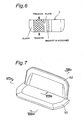
- Fig. 7 depicts an example of the above-described conventional thin seats, which is built for two persons and includes a seat cushion 50 having a 3-D net and a seat back 52 extending upwards from a rear edge of the seat cushion 50.
- the seat cushion 50 includes a seat cushion frame 54 and a 3-D net 56 stretched over the seat cushion frame 54.
- An outer edge portion of the 3-D net 56 is sewn to an inner edge portion of a trim material (skin) 58 and that of a tension member 60, while an outer edge portion of the trim material 58 and that of the tension member 60 are wound around the seat cushion frame 54 and then engaged with a trim retainer 64 by a retainer piece 62, thereby applying a predetermined tension to the seat cushion 50.
- the present invention has been developed to overcome the above-described disadvantages inherent in the prior art and is intended to provide a thin seat having improved cushioning characteristics that enables a seat occupant to have a good posture and can withstand a long-term use.
- the thin seat according to the present invention is characterized by comprising a frame and a cushioning material stretched over the frame, wherein a tension is applied to the cushioning material substantially only in a longitudinal direction thereof by engaging only front and rear edges of the cushioning material with the frame.
- the thin seat is also characterized by further comprising a reinforcement patch provided on a central portion of the cushioning material in a widthwise direction thereof.
- the thin seat is characterized in that a material of the reinforcement patch is identical with that of the cushioning material.
- the thin seat is also characterized in that the cushioning material comprises an elastic cloth having warps and wefts different in tensile characteristics, and the wefts have a larger spring constant than the warps.
- the thin seat is also characterized by further comprising a trim material covered on the elastic cloth and a 3-D net or urethane interposed between the elastic cloth and the trim material.
- the thin seat is further characterized in that end portions of the elastic cloth in a widthwise direction of the seat are loosened.
- Fig. 1, Fig. 2 and Figs. 3A to 3C depict a thin seat S according to the present invention having an appearance substantially similar to that of the conventional thin seat of Fig. 7.
- the thin seat S includes a seat cushion 2 and a seat back 4 extending upwards from a rear edge of the seat cushion 2.
- the seat cushion 2 includes a seat cushion frame 6, an elastic cloth 8 employed as a cushioning material and stretched over the seat cushion frame 6, and a 3-D net 10 covered with a trim material (skin) 12.
- the elastic cloth 8 has a first engaging portion 8a formed at a front edge thereof and a second engaging portion 8b formed at a rear edge thereof.
- the first engaging portion 8a engages at a distal end portion thereof with a trim retainer 14 joined to the seat cushion frame 6,
- the second engaging portion 8b similarly engages at a distal end portion thereof with a trim retainer 16 joined to the seat cushion frame 6, and
- the elastic cloth 8 engages at an intermediate portion thereof with the trim retainer 14 via a retainer piece 18, thereby applying a predetermined tension to the elastic cloth 8 in the longitudinal direction of the seat.
- the tension in the widthwise direction of the seat is so set as to be quasi zero (elongation: about 0 ⁇ 5%) and, hence, practically no tension is created in this direction.
- Respective side portions of the 3-D net 10 interposed between the elastic cloth 8 and the trim material 12 are clamped between the seat cushion frame 6 and the trim material 12.
- a cloth made up of warps (yarns extending in the longitudinal direction of the seat S) and wefts (yarns extending in the widthwise direction of the seat S) having different tensile characteristics may be used for the elastic cloth 8.
- warps in which a tension is created, having a larger elongation to load than wefts enhances the cushioning characteristics.
- Fig. 4 is a graph indicating the static characteristics (tensile characteristics) where a cloth woven with the use of elastic yarns (softened spring) as warps and polyester-based fibers (linear spring) as wefts has been used for the elastic cloth 8.
- static characteristics have been obtained by using test pieces cut off from an elastic cloth material into a size of 200mmL ⁇ 50mmW and by pulling them at a speed of 50mm/min in the longitudinal direction thereof while gripping opposite end portions thereof to a length 50mm inwards.
- the tensile characteristics of the elastic yarns have been obtained using the test pieces that have elastic yarns extending in the longitudinal direction thereof, while the tensile characteristics of the polyester-based fibers have been obtained using the test pieces that have polyester-based fibers extending in the longitudinal direction thereof.
- the elastic cloth 8 has a tendency to easily elongate in the longitudinal direction thereof because the warps have a larger elongation to load than the wefts. If a long stroke is desired, the use of wefts having non-linear characteristics relative to the initial load is required. However, if linear springs have substantially the same spring constant, they may have an allowable deflection in the range of 0 ⁇ 10mm or a maximum deflection of 20mm at a load of zero.
- the elastic cloth 8 has a rectangular reinforcement patch 20 sewn thereto at a rear region of a central portion in the widthwise direction thereof.
- a material similar to the elastic cloth 8 can be used for the reinforcement patch 20.
- an arrow A indicates the direction in which the tension is applied in the sitting condition, and this direction coincides with the direction in which the warps extend.
- a range L in the widthwise direction indicates the range in which the longitudinal tension is applied, and coincides with the length of the first engaging portion 8a.
- the trim material 12 has a first engaging portion 12a formed at a front edge thereof and a second engaging portion 12b formed at a rear edge thereof.
- the first engaging portion 12a together with the first engaging portion 8a of the elastic cloth 8 engages at a distal end portion thereof with the trim retainer 14, while the second engaging portion 12b together with the second engaging portion 8b of the elastic cloth 8 similarly engages at a distal end portion thereof with the trim retainer 16, thereby applying a predetermined tension to the trim material 12.
- Fig. 5 depicts several portions on the seat cushion 2 that have different tensions in the sitting condition.
- a central region B in the widthwise direction has a larger tension and a higher rigidity than a sitting region C. Accordingly, the region B is short in stroke, and a member such as a frame or the like can be arranged there, if necessary.
- a side region D in the widthwise direction indicates the region where the side portion 8c of the elastic cloth 8 is loosened.
- a longitudinal tension is applied to the sitting region by increasing the rigidity of the central region of the seat cushion 2 in the widthwise direction and by loosening a portion between the central region and the sitting region. That is, it is sufficient if end portions of the elastic cloth 8 positioned between the central region and the sitting region are caused to engage with respective trim retainers under a loosened condition or not to engage therewith.
- a 3-D net 10 is interposed between an elastic cloth 8 and a trim material 12, an elastic material such as urethane may be used in place of the 3-D net 10.
- the seat back 4 is made up of a plate material 22, a cushioning material 24 covered on the plate material 22, and a trim material (skin) 26 covered on the cushioning material 24, a 3-D net may be used for the cushioning material 24.
- the thin seat S of the above-described construction can be used for a folding wheelchair.
- a predetermined tension be applied not only in the longitudinal direction of the seat but also in the widthwise direction of the seat.
- the seat according to the present invention constructed in the manner as described above offers the following effects.
- a tension is applied to a cushioning material substantially only in a longitudinal direction thereof by engaging only front and rear edges of the cushioning material with a frame, no side pressure is applied to a seat occupant, unlike conventional thin seats. Accordingly, it is possible to provide a thin seat having improved cushioning characteristics that enables the seat occupant to have a good posture and can withstand a long-term use.
- a reinforcement patch is provided on a central portion of the cushioning material in a widthwise direction thereof, even when two persons sit on the seat, the influence of the body weight can be reduced, making it possible to prevent their postures from inclining and enhance the sitting feeling.
- the elastic cloth is covered with a trim material and a 3-D net or urethane is interposed between the elastic cloth and the trim material, a thin and lightweight thin seat having improved cushioning characteristics can be provided.
Landscapes
- Engineering & Computer Science (AREA)
- General Health & Medical Sciences (AREA)
- Animal Behavior & Ethology (AREA)
- Health & Medical Sciences (AREA)
- Public Health (AREA)
- Veterinary Medicine (AREA)
- Life Sciences & Earth Sciences (AREA)
- Aviation & Aerospace Engineering (AREA)
- Transportation (AREA)
- Mechanical Engineering (AREA)
- Seats For Vehicles (AREA)
- Mattresses And Other Support Structures For Chairs And Beds (AREA)
- Woven Fabrics (AREA)
Abstract
Description
Claims (6)
- A thin seat is characterized by comprising a frame and a cushioning material stretched over the frame, wherein a tension is applied to the cushioning material substantially only in a longitudinal direction thereof by engaging only front and rear edges of the cushioning material with the frame.
- The thin seat according to claim 1, further comprising a reinforcement patch provided on a central portion of the cushioning material in a widthwise direction thereof.
- The thin seat according to claim 2, wherein a material of the reinforcement patch is identical with that of the cushioning material.
- The thin seat according to any one of claims 1 to 3, wherein the cushioning material comprises an elastic cloth having warps and wefts different in tensile characteristics, and the wefts have a larger spring constant than the warps.
- The thin seat according to claim 4, further comprising a trim material covered on the elastic cloth and a 3-D net or urethane interposed between the elastic cloth and the trim material.
- The thin seat according to claim 4 or 5, wherein end portions of the elastic cloth in a widthwise direction of the seat are loosened.
Applications Claiming Priority (3)
| Application Number | Priority Date | Filing Date | Title |
|---|---|---|---|
| JP2002229640 | 2002-08-07 | ||
| JP2002229640 | 2002-08-07 | ||
| PCT/JP2003/010043 WO2004014192A1 (en) | 2002-08-07 | 2003-08-07 | Thin seat |
Publications (3)
| Publication Number | Publication Date |
|---|---|
| EP1454571A1 true EP1454571A1 (en) | 2004-09-08 |
| EP1454571A4 EP1454571A4 (en) | 2005-07-27 |
| EP1454571B1 EP1454571B1 (en) | 2010-03-17 |
Family
ID=31711661
Family Applications (1)
| Application Number | Title | Priority Date | Filing Date |
|---|---|---|---|
| EP03784561A Expired - Lifetime EP1454571B1 (en) | 2002-08-07 | 2003-08-07 | Thin two persons seat |
Country Status (7)
| Country | Link |
|---|---|
| US (1) | US7455366B2 (en) |
| EP (1) | EP1454571B1 (en) |
| JP (1) | JP4520300B2 (en) |
| KR (1) | KR100704102B1 (en) |
| CN (1) | CN1294866C (en) |
| DE (1) | DE60331719D1 (en) |
| WO (1) | WO2004014192A1 (en) |
Cited By (5)
| Publication number | Priority date | Publication date | Assignee | Title |
|---|---|---|---|---|
| FR2885091A1 (en) * | 2005-04-28 | 2006-11-03 | Cera | Folding seat for motor vehicle has thin layer of foam supported by textile layer with warp filament elasticity providing adequate comfort |
| WO2011088534A1 (en) * | 2010-01-21 | 2011-07-28 | Marcopolo S.A. | Deformable seat with a reduced thickness for passenger transport vehicles |
| EP2937019A1 (en) * | 2007-09-20 | 2015-10-28 | Herman Miller, Inc. | Load support structure |
| EP3300947A1 (en) * | 2016-10-03 | 2018-04-04 | Toyota Jidosha Kabushiki Kaisha | Vehicle seat |
| US10874220B2 (en) | 2015-01-16 | 2020-12-29 | Herman Miller, Inc. | Zoned suspension seating structure |
Families Citing this family (9)
| Publication number | Priority date | Publication date | Assignee | Title |
|---|---|---|---|---|
| US8449032B2 (en) | 2010-05-28 | 2013-05-28 | Drive Medical Design & Mfg. | Wheelchair having an adjustable seat |
| WO2011155525A1 (en) * | 2010-06-11 | 2011-12-15 | 株式会社岡村製作所 | Furniture fabric and chair |
| JP5922097B2 (en) | 2011-03-23 | 2016-05-24 | 株式会社デルタツーリング | Cushion member and seat structure |
| US11229294B2 (en) | 2012-09-20 | 2022-01-25 | Steelcase Inc. | Chair assembly with upholstery covering |
| USD697726S1 (en) | 2012-09-20 | 2014-01-21 | Steelcase Inc. | Chair |
| US11304528B2 (en) | 2012-09-20 | 2022-04-19 | Steelcase Inc. | Chair assembly with upholstery covering |
| US8998339B2 (en) | 2012-09-20 | 2015-04-07 | Steelcase Inc. | Chair assembly with upholstery covering |
| JP2016084009A (en) * | 2014-10-24 | 2016-05-19 | トヨタ自動車株式会社 | Vehicle seat |
| JP6835634B2 (en) * | 2016-10-03 | 2021-02-24 | トヨタ自動車株式会社 | Vehicle seat |
Family Cites Families (19)
| Publication number | Priority date | Publication date | Assignee | Title |
|---|---|---|---|---|
| GB1119818A (en) | 1967-03-22 | 1968-07-10 | Maximilian Heller | Resiliently extensible sheet-surface for chairs or the like |
| GB1454059A (en) * | 1974-08-13 | 1976-10-27 | Antiference Ltd | Seats |
| US3981538A (en) * | 1975-07-31 | 1976-09-21 | Pirelli Limited | Resilient platforms for seating |
| US4077669A (en) * | 1977-01-19 | 1978-03-07 | Louis Fox | Self-centering posture seat |
| IT8321298U1 (en) * | 1983-03-28 | 1984-09-28 | Intercommerz Union Icu | FOLDING CHAIR WITH ELASTIC BAND FOR TENSIONING THE SEAT AND BACKREST COVER. |
| DE3342259C2 (en) * | 1983-11-23 | 1994-10-27 | Paulisch Kg | Upholstered chair |
| JP2556492B2 (en) * | 1986-12-24 | 1996-11-20 | キヤノン株式会社 | Reproduction device and reproduction method |
| JPH0527883Y2 (en) * | 1987-04-09 | 1993-07-16 | ||
| JPS6414053U (en) | 1987-07-15 | 1989-01-24 | ||
| JPH0195142A (en) | 1987-10-07 | 1989-04-13 | Toa Nenryo Kogyo Kk | Preparation of thermoplastic resin composition |
| JPH0195142U (en) * | 1987-12-15 | 1989-06-23 | ||
| CN2038742U (en) | 1988-01-10 | 1989-06-07 | 王文波 | Folding stool made of aluminium alloy |
| US5735578A (en) * | 1995-03-27 | 1998-04-07 | Burns Aerospace Corporation | Quick replacement seat bottom diaphragm |
| FR2762498B1 (en) * | 1997-04-25 | 1999-06-04 | Lafuma Sa | CARRIER CANVAS ARMCHAIR |
| JP2000070078A (en) * | 1998-08-27 | 2000-03-07 | Ikeda Bussan Co Ltd | Seat for vehicle |
| JP2000079840A (en) | 1998-09-04 | 2000-03-21 | Komatsu Ltd | Vehicle seat |
| JP3772612B2 (en) | 1999-11-05 | 2006-05-10 | 日産自動車株式会社 | Sheet |
| JP4380896B2 (en) | 2000-08-02 | 2009-12-09 | 株式会社デルタツーリング | Sheet |
| EP1157640A2 (en) * | 2000-05-26 | 2001-11-28 | GKD GEBR. KUFFERATH GMBH & CO. KG | Furniture |
-
2003
- 2003-08-07 WO PCT/JP2003/010043 patent/WO2004014192A1/en not_active Ceased
- 2003-08-07 KR KR1020047008393A patent/KR100704102B1/en not_active Expired - Fee Related
- 2003-08-07 EP EP03784561A patent/EP1454571B1/en not_active Expired - Lifetime
- 2003-08-07 US US10/496,133 patent/US7455366B2/en not_active Expired - Lifetime
- 2003-08-07 DE DE60331719T patent/DE60331719D1/en not_active Expired - Lifetime
- 2003-08-07 CN CNB038019787A patent/CN1294866C/en not_active Expired - Fee Related
- 2003-08-07 JP JP2004527353A patent/JP4520300B2/en not_active Expired - Fee Related
Cited By (12)
| Publication number | Priority date | Publication date | Assignee | Title |
|---|---|---|---|---|
| FR2885091A1 (en) * | 2005-04-28 | 2006-11-03 | Cera | Folding seat for motor vehicle has thin layer of foam supported by textile layer with warp filament elasticity providing adequate comfort |
| EP2937019A1 (en) * | 2007-09-20 | 2015-10-28 | Herman Miller, Inc. | Load support structure |
| US9668580B2 (en) | 2007-09-20 | 2017-06-06 | Herman Miller, Inc. | Load support structure |
| US10016060B2 (en) | 2007-09-20 | 2018-07-10 | Herman Miller, Inc. | Load support structure |
| US10820706B2 (en) | 2007-09-20 | 2020-11-03 | Herman Miller, Inc. | Load support structure |
| US10856662B2 (en) | 2007-09-20 | 2020-12-08 | Herman Miller, Inc. | Load support structure |
| US11330905B2 (en) | 2007-09-20 | 2022-05-17 | MillerKnoll, Inc. | Load support structure |
| WO2011088534A1 (en) * | 2010-01-21 | 2011-07-28 | Marcopolo S.A. | Deformable seat with a reduced thickness for passenger transport vehicles |
| US10874220B2 (en) | 2015-01-16 | 2020-12-29 | Herman Miller, Inc. | Zoned suspension seating structure |
| US11825957B2 (en) | 2015-01-16 | 2023-11-28 | MillerKnoll, Inc. | Zoned suspension seating structure |
| EP3300947A1 (en) * | 2016-10-03 | 2018-04-04 | Toyota Jidosha Kabushiki Kaisha | Vehicle seat |
| US10434911B2 (en) | 2016-10-03 | 2019-10-08 | Toyota Jidosha Kabushiki Kaisha | Vehicle seat including a cloth spring member |
Also Published As
| Publication number | Publication date |
|---|---|
| WO2004014192A8 (en) | 2005-01-20 |
| DE60331719D1 (en) | 2010-04-29 |
| US7455366B2 (en) | 2008-11-25 |
| CN1294866C (en) | 2007-01-17 |
| US20040262976A1 (en) | 2004-12-30 |
| CN1612704A (en) | 2005-05-04 |
| KR100704102B1 (en) | 2007-04-05 |
| EP1454571B1 (en) | 2010-03-17 |
| WO2004014192A1 (en) | 2004-02-19 |
| JP4520300B2 (en) | 2010-08-04 |
| EP1454571A4 (en) | 2005-07-27 |
| JPWO2004014192A1 (en) | 2005-11-24 |
| KR20040073447A (en) | 2004-08-19 |
Similar Documents
| Publication | Publication Date | Title |
|---|---|---|
| EP1193120B1 (en) | Vehicle seat | |
| US7025423B2 (en) | Seat structure | |
| EP1454571B1 (en) | Thin two persons seat | |
| US7128371B2 (en) | Seat structure | |
| US7731294B2 (en) | Seat | |
| US5393126A (en) | Tubular frame seating structure with tension sleeve | |
| EP1226999B1 (en) | Vehicle seat | |
| US6435618B1 (en) | Seat | |
| DE60314931T2 (en) | seat structure | |
| KR100601765B1 (en) | Seat structure | |
| EP0342790A1 (en) | Elastomeric woven mat seat suspension | |
| US20040232743A1 (en) | Seat structure | |
| US4761035A (en) | Seat cushion assembly | |
| EP1743800B1 (en) | Seat | |
| WO2016059876A1 (en) | Lumbar support structure and seat structure | |
| KR100355319B1 (en) | Cushion structure having a three-dimensional net | |
| JP2006042848A (en) | Chair | |
| US6932432B2 (en) | Seat structure | |
| JP2002199955A (en) | Seat with three-dimensional net | |
| JP2002177091A (en) | Seat for vehicle | |
| JPH02257912A (en) | Spring for vehicle seat |
Legal Events
| Date | Code | Title | Description |
|---|---|---|---|
| PUAI | Public reference made under article 153(3) epc to a published international application that has entered the european phase |
Free format text: ORIGINAL CODE: 0009012 |
|
| 17P | Request for examination filed |
Effective date: 20040604 |
|
| AK | Designated contracting states |
Kind code of ref document: A1 Designated state(s): AT BE BG CH CY CZ DE DK EE ES FI FR GB GR HU IE IT LI LU MC NL PT RO SE SI SK TR |
|
| A4 | Supplementary search report drawn up and despatched |
Effective date: 20050609 |
|
| RBV | Designated contracting states (corrected) |
Designated state(s): DE FR GB |
|
| 17Q | First examination report despatched |
Effective date: 20061218 |
|
| 17Q | First examination report despatched |
Effective date: 20061218 |
|
| RTI1 | Title (correction) |
Free format text: THIN TWO PERSTONS SEAT |
|
| GRAP | Despatch of communication of intention to grant a patent |
Free format text: ORIGINAL CODE: EPIDOSNIGR1 |
|
| RTI1 | Title (correction) |
Free format text: THIN TWO PERSONS SEAT |
|
| GRAS | Grant fee paid |
Free format text: ORIGINAL CODE: EPIDOSNIGR3 |
|
| GRAA | (expected) grant |
Free format text: ORIGINAL CODE: 0009210 |
|
| AK | Designated contracting states |
Kind code of ref document: B1 Designated state(s): DE FR GB |
|
| REG | Reference to a national code |
Ref country code: GB Ref legal event code: FG4D |
|
| REF | Corresponds to: |
Ref document number: 60331719 Country of ref document: DE Date of ref document: 20100429 Kind code of ref document: P |
|
| PLBE | No opposition filed within time limit |
Free format text: ORIGINAL CODE: 0009261 |
|
| STAA | Information on the status of an ep patent application or granted ep patent |
Free format text: STATUS: NO OPPOSITION FILED WITHIN TIME LIMIT |
|
| 26N | No opposition filed |
Effective date: 20101220 |
|
| REG | Reference to a national code |
Ref country code: FR Ref legal event code: PLFP Year of fee payment: 14 |
|
| REG | Reference to a national code |
Ref country code: FR Ref legal event code: PLFP Year of fee payment: 15 |
|
| PGFP | Annual fee paid to national office [announced via postgrant information from national office to epo] |
Ref country code: FR Payment date: 20170707 Year of fee payment: 15 Ref country code: GB Payment date: 20170825 Year of fee payment: 15 Ref country code: DE Payment date: 20170905 Year of fee payment: 15 |
|
| REG | Reference to a national code |
Ref country code: DE Ref legal event code: R119 Ref document number: 60331719 Country of ref document: DE |
|
| GBPC | Gb: european patent ceased through non-payment of renewal fee |
Effective date: 20180807 |
|
| PG25 | Lapsed in a contracting state [announced via postgrant information from national office to epo] |
Ref country code: DE Free format text: LAPSE BECAUSE OF NON-PAYMENT OF DUE FEES Effective date: 20190301 |
|
| PG25 | Lapsed in a contracting state [announced via postgrant information from national office to epo] |
Ref country code: FR Free format text: LAPSE BECAUSE OF NON-PAYMENT OF DUE FEES Effective date: 20180831 |
|
| PG25 | Lapsed in a contracting state [announced via postgrant information from national office to epo] |
Ref country code: GB Free format text: LAPSE BECAUSE OF NON-PAYMENT OF DUE FEES Effective date: 20180807 |