EP1454568A2 - Chair, particularly office-chair - Google Patents
Chair, particularly office-chair Download PDFInfo
- Publication number
- EP1454568A2 EP1454568A2 EP04004811A EP04004811A EP1454568A2 EP 1454568 A2 EP1454568 A2 EP 1454568A2 EP 04004811 A EP04004811 A EP 04004811A EP 04004811 A EP04004811 A EP 04004811A EP 1454568 A2 EP1454568 A2 EP 1454568A2
- Authority
- EP
- European Patent Office
- Prior art keywords
- chair
- support part
- seat support
- bolt
- pivot axis
- Prior art date
- Legal status (The legal status is an assumption and is not a legal conclusion. Google has not performed a legal analysis and makes no representation as to the accuracy of the status listed.)
- Granted
Links
- 230000008878 coupling Effects 0.000 claims description 9
- 238000010168 coupling process Methods 0.000 claims description 9
- 238000005859 coupling reaction Methods 0.000 claims description 9
- 230000002093 peripheral effect Effects 0.000 claims description 5
- NJPPVKZQTLUDBO-UHFFFAOYSA-N novaluron Chemical compound C1=C(Cl)C(OC(F)(F)C(OC(F)(F)F)F)=CC=C1NC(=O)NC(=O)C1=C(F)C=CC=C1F NJPPVKZQTLUDBO-UHFFFAOYSA-N 0.000 claims description 3
- 238000010276 construction Methods 0.000 abstract 1
- 230000006835 compression Effects 0.000 description 12
- 238000007906 compression Methods 0.000 description 12
- 230000001360 synchronised effect Effects 0.000 description 10
- 238000004146 energy storage Methods 0.000 description 4
- 230000005540 biological transmission Effects 0.000 description 1
- 230000000295 complement effect Effects 0.000 description 1
- 230000000994 depressogenic effect Effects 0.000 description 1
- 230000001404 mediated effect Effects 0.000 description 1
- 230000000149 penetrating effect Effects 0.000 description 1
- 230000035515 penetration Effects 0.000 description 1
Images


Classifications
-
- A—HUMAN NECESSITIES
- A47—FURNITURE; DOMESTIC ARTICLES OR APPLIANCES; COFFEE MILLS; SPICE MILLS; SUCTION CLEANERS IN GENERAL
- A47C—CHAIRS; SOFAS; BEDS
- A47C1/00—Chairs adapted for special purposes
- A47C1/02—Reclining or easy chairs
- A47C1/031—Reclining or easy chairs having coupled concurrently adjustable supporting parts
- A47C1/032—Reclining or easy chairs having coupled concurrently adjustable supporting parts the parts being movably-coupled seat and back-rest
- A47C1/03255—Reclining or easy chairs having coupled concurrently adjustable supporting parts the parts being movably-coupled seat and back-rest with a central column, e.g. rocking office chairs
-
- A—HUMAN NECESSITIES
- A47—FURNITURE; DOMESTIC ARTICLES OR APPLIANCES; COFFEE MILLS; SPICE MILLS; SUCTION CLEANERS IN GENERAL
- A47C—CHAIRS; SOFAS; BEDS
- A47C1/00—Chairs adapted for special purposes
- A47C1/02—Reclining or easy chairs
- A47C1/031—Reclining or easy chairs having coupled concurrently adjustable supporting parts
- A47C1/032—Reclining or easy chairs having coupled concurrently adjustable supporting parts the parts being movably-coupled seat and back-rest
- A47C1/03205—Reclining or easy chairs having coupled concurrently adjustable supporting parts the parts being movably-coupled seat and back-rest having adjustable and lockable inclination
- A47C1/03233—Reclining or easy chairs having coupled concurrently adjustable supporting parts the parts being movably-coupled seat and back-rest having adjustable and lockable inclination by means of a rack-and-pinion or like gearing mechanism
-
- A—HUMAN NECESSITIES
- A47—FURNITURE; DOMESTIC ARTICLES OR APPLIANCES; COFFEE MILLS; SPICE MILLS; SUCTION CLEANERS IN GENERAL
- A47C—CHAIRS; SOFAS; BEDS
- A47C1/00—Chairs adapted for special purposes
- A47C1/02—Reclining or easy chairs
- A47C1/031—Reclining or easy chairs having coupled concurrently adjustable supporting parts
- A47C1/032—Reclining or easy chairs having coupled concurrently adjustable supporting parts the parts being movably-coupled seat and back-rest
- A47C1/03205—Reclining or easy chairs having coupled concurrently adjustable supporting parts the parts being movably-coupled seat and back-rest having adjustable and lockable inclination
- A47C1/03238—Reclining or easy chairs having coupled concurrently adjustable supporting parts the parts being movably-coupled seat and back-rest having adjustable and lockable inclination by means of peg-and-notch or pawl-and-ratchet mechanism
-
- A—HUMAN NECESSITIES
- A47—FURNITURE; DOMESTIC ARTICLES OR APPLIANCES; COFFEE MILLS; SPICE MILLS; SUCTION CLEANERS IN GENERAL
- A47C—CHAIRS; SOFAS; BEDS
- A47C1/00—Chairs adapted for special purposes
- A47C1/02—Reclining or easy chairs
- A47C1/031—Reclining or easy chairs having coupled concurrently adjustable supporting parts
- A47C1/032—Reclining or easy chairs having coupled concurrently adjustable supporting parts the parts being movably-coupled seat and back-rest
- A47C1/03261—Reclining or easy chairs having coupled concurrently adjustable supporting parts the parts being movably-coupled seat and back-rest characterised by elastic means
- A47C1/03266—Reclining or easy chairs having coupled concurrently adjustable supporting parts the parts being movably-coupled seat and back-rest characterised by elastic means with adjustable elasticity
-
- A—HUMAN NECESSITIES
- A47—FURNITURE; DOMESTIC ARTICLES OR APPLIANCES; COFFEE MILLS; SPICE MILLS; SUCTION CLEANERS IN GENERAL
- A47C—CHAIRS; SOFAS; BEDS
- A47C1/00—Chairs adapted for special purposes
- A47C1/02—Reclining or easy chairs
- A47C1/031—Reclining or easy chairs having coupled concurrently adjustable supporting parts
- A47C1/032—Reclining or easy chairs having coupled concurrently adjustable supporting parts the parts being movably-coupled seat and back-rest
- A47C1/03261—Reclining or easy chairs having coupled concurrently adjustable supporting parts the parts being movably-coupled seat and back-rest characterised by elastic means
- A47C1/03272—Reclining or easy chairs having coupled concurrently adjustable supporting parts the parts being movably-coupled seat and back-rest characterised by elastic means with coil springs
Definitions
- the invention relates to a chair, in particular an office chair, after Preamble of claim 1.
- Such a chair is known from DE 43 24 545 A1.
- a so-called synchronous mechanism at the backrest and seat in a certain predetermined ratio to be pivoted simultaneously.
- a power storage in the form of a helical compression spring arranged, by means of between the front seat support part and the rear seat support member is generated a force which the backrest in its front end position and the rear area of the seat pushes in its upper position.
- a so-called seesaw mechanism given that is, the user can against the restoring force of the backrest bobbing with your back.
- the synchronous mechanism can be locked so that there is no relative movement between the seat support parts can be done more.
- a catch or locking the synchronous mechanism takes place in situations in which the user does not want mobility of the backrest. If the locking is done in an upright position of the backrest, the resulting seating position can be adjusted by the user with the Time to be uncomfortable.
- the invention is therefore based on the object, a better to the needs the user adapted locking device at a To create chair of the type mentioned.
- the locking device rather, provides a plurality of discrete locking positions the seat support parts ready for each other. It is therefore possible the Synchronous mechanism if required in a relatively upright or in one compared to lock inclined position of the backrest. Of course, you can also have more than two locking positions pretend.
- a stepless specification of locking positions by appropriate design of the locking device, for example, by a corresponding clamping mechanism, possible.
- a locking device according to claim 2 can be constructive with realize little effort, the locking device in the single discrete locking positions also larger load forces can withstand. As a rule, there are some locking positions, For example, four locking positions, sufficient.
- a locking device according to claim 3 is structurally simple and still safe.
- the locking device according to claim 4 ensured that the bolt and the counter body in a change of Relative positions of the seat support parts before locking their distance not significantly change each other, so that the stroke of the locking movement from the predetermined relative position between the seat support parts is essentially independent. This increases the ease of use of Locking device.
- a locking device In a locking device according to claim 5 is a specific Relative position between bar and counter-body of a relative position clearly assigned between the two seat support parts. This increases the Operating safety of the locking device.
- the pivot axis between the components of the locking device, ie the counter body and the bolt, may, but need not, with the pivot axis between the two seat support parts coincide.
- a coupling element can be a Translation between the relative pivoting of the components of the Locking device on the one hand and the seat support parts on the other pretend. Even with relatively far apart arranged Locking positions, as far as the locking device, can in this way finely graduated locking positions, what the Wegturimaschine anxx, realized.
- Fig. 1 shows an office chair with a chair frame 1. This is with a Pedestal 2 provided, which is about rollers 3 with respect to the ground supported. On the pedestal 2 is a height-adjustable chair column. 4 attached, at whose upper end a seat support 5 is attached. The latter is designed in two parts; he has a front seat support part 6, the on the chair column 4 is fixed, and a rear seat support part 7, the above the chair column 4 by means of a rotatable about a pivot axis 8 Swivel joint is articulated on the front seat support part 6.
- a support tube 9 is fixed, which is parallel to the pivot axis 8 extends. On this support tube 9 is based Seat 10 shortly behind its leading edge 11 from.
- the support tube 9 therefore represents a front support portion for the seat 10.
- the seat 10 is supported in its rear region on a support shaft 12 from the rear seat support part 7 is stored.
- the support shaft 12 therefore provides a rear support portion for the seat 10.
- At the rear seat support part 7 is still arranged a seat tilt adjustment 13.
- a backrest height adjustment device 16 is provided.
- the described embodiment of the seat support 5 with the arrangement of Seat 10 and the backrest 15 forms a so-called synchronous mechanism.
- a total provided with 17 designated force variation device that still will be explained in detail.
- Part of the force changing device 17 is a over the front seat support member 6 downwardly projecting adjusting nut 18, of which in Fig. 1, a freely rotatable cap 19 is visible.
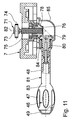
- the chair column 4 has the height adjustment of the seat support 5 with the seat 10 and the backrest 15 a known length-adjustable gas spring 21st on, which is shown in Fig. 3 in plan view.
- the gas spring 21 is in a Cone formed clamping device 22 of the front seat support part. 6 held clamped. From the gas spring 21 projects upwards a valve actuating pin 23 out, when it is inserted into the gas spring 21 a there existing valve is opened, causing length adjustments of the gas spring 21 become possible.
- Such gas springs are for example in the DE 18 12 282 C2 (corresponding to US Pat. No. 3,656,593).
- valve operating lever 24 To actuate the valve actuating pin 23 is a two-armed Valve operating lever 24 is provided, which pivotally against the Swivel axis 8 is supported, as described for example in DE 43 24 545 A1 is.
- a first lever arm 25 of the valve operating lever 24 is located against the valve actuating pin 23, while the second lever arm 26th be actuated by a known from DE 43 24 545 A 1 lever mechanism can.
- a pivoting of the rear seat support part 7 relative to the front Seat support part 6 of the synchronous mechanism counteracts an energy storage 27, which is in the illustrated embodiment, a biased Screw compression spring 28 is.
- a biased Screw compression spring 28 is.
- the energy storage 27th a helical compression spring 28 passing through the guide rod 30.
- the compression coil spring 28 is supported against a shoe 31 of the force changing device 17 from.
- the sliding shoe 31 in turn abuts against a sliding surface 32, which at a first, short lever arm 33 of the rear seat support part 7 is formed.
- the lever arm 33 is integrally formed with the rear seat support member 7 and extends from the pivot axis 8 from substantially downwards.
- Geometric In this respect, the rear seat support part 7 is designed as an angle lever.
- On the guide rod 30 of the slide shoe 31 along the helical compression spring 28 movable. At one of the abutment 29 opposite Adjustment section 34 of the guide rod 30 engages the force changing device 17 on. A adjoining the adjusting portion 34 connecting portion 35 of the guide rod 30 passes through the first lever arm 33 of the rear seat support member 7.
- the screw compression spring 28 penetrating portion of the guide rod 30 Opposite the screw compression spring 28 penetrating portion of the guide rod 30 is the Connecting portion 35 toward the rear seat support member 7 angled.
- the adjusting portion 34 of the guide rod 30 is therefore on the bent back seat support part 7 to and the seat support 5 adjacent arranged.
- Part of the force changing device 17 is an adjusting screw 36, the on the adjusting portion 34 of the guide rod 30 via a pivot joint with Swivel axis 37 is pivotally articulated.
- the distance between the pivot axis 8 between the seat support parts 6, 7 on the one hand and the central axis of the helical compression spring 28 on the other is designated in Fig. 5 with a.
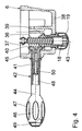
- the adjusting screw 36 engages in the adjusting nut 18, which in a lower Wall 38 of the front seat support member 6 rotatably, but in the direction of the screw 36 is mounted immovably.
- the adjusting nut 18 On the cap 19 opposite End, the adjusting nut 18 has a straight toothed conical section 39 on. In the sprocket of this engages a likewise straight toothed Cone portion 40 of an end portion 41 of an actuating rotary handle 42 on.
- the two cone sections 39, 40 thus form a straight-toothed Bevel gear.
- a rotation axis 43 of the adjusting screw 36 and an axis of rotation 44 of the actuating rotary handle 42 are not aligned with each other, but intersect and close a right one with each other Angle.
- the end portion 41 is in a side wall 45 of the front Seat support part 6 rotatably, but axially to the axis of rotation 44 of the actuating rotary handle 42 immovably stored.
- the free end of the actuating rotary handle 42 is as an oval handle 46th formed with recessed grips 47.
- the handle 46 has a central bore 48, which at the free end of the handle 46 by a depressed Cap 49 is closed. Introduced into the hole is a Connecting screw 50, which the handle 46 at the end portion 41 of Actuator rotary handle 42 holds.
- the sliding surface 32 at least approximately a circular arc section lies whose center above the axis the pivot joint of the abutment 29 is formed, changes at a rotation of the actuating rotary handle 42 a distance b between the pivot axis of the abutment 29 and the penetration of the axis of the energy storage 27 by the sliding surface 32 only slightly. Therefore changes in such adjustments, the bias of the coil compression spring 28 practically not.
- the sliding surface 32 formed by the abutment 29 Swivel joint is achieved that on the screw 36 is always a transmitted by the compression coil spring 28 mediated tensile force. This leads to to that the set screw 36 in the adjusting nut 18 always defined in such a way is guided, that in Fig. 5 overhead thread flanks of the thread the adjusting screw 36 to the corresponding thread flanks of the internal thread the adjusting nut 18 abut.
- the of the helical compression spring 28 on the first lever arm 33 of the rear Seat support part 7 acting force is therefore not changed; it will merely by changing the distance a between the axis of Force accumulator 27 and the pivot axis 8 of the effective lever arm, the Overall, that is from the helical compression spring 28 on the rear Seat support part 7 and thus on the seat 10 and the backrest 15 acting Torque, changed.
- This torque becomes smaller, the smaller the distance is a and vice versa.
- the on the actuating handle 42nd applied adjusting forces over the entire adjustment of the shoe 31 can be kept constant, as frictional forces between the shoe 31 and the sliding surface 32 and also the actuating forces the mechanical coupling between the guide rod 30 and the actuating knob 42 practically do not change.
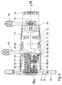
- Locking device 50 To the joint pivoting of the seat 10 and the backrest 15 in the synchro-mechanics against the force of the helical compression spring To be able to switch off 28 is one shown in FIGS. 6 to 8 Locking device 50 is provided.
- the locking device 50 includes a latch 51, which at the front seat support part 6 to a Swivel joint with pivot axis 52 is pivoted.
- the Pivot axis 52 substantially coincides with that of abutment 29 together.
- the bolt 51 At its free, remote from the pivot axis 52 end the bolt 51 has a horizontally arranged locking bolt 53, which is fixed to the bolt 51 and passes through it in such a way that it leads to both Sides over the bar 51 in the horizontal direction.
- Part of the locking device 50 is a cooperating with the latch 51 Counter body 54. This is on the front seat support part 6 to a Swivel joint with pivot axis 55 pivotally articulated.
- the Swivel axes 52, 55 are spaced apart and parallel.
- the counterbody 54 has two spaced apart, parallel, vertical and Plates 56 arranged perpendicular to the pivot axis 55. These have in rough approximation, a triangular shape, wherein the pivot axis 55 opposite side as a bar-peripheral portion 57 approximated is located on a circular arc section whose center through the Swivel axis 55 is formed.
- each substantially semi-circular latch receptacles 58 formed, wherein in each case two bolt receptacles in each one of the plates 56 in pairs with each other aligned.
- the width of the bolt receptacles 58 is complementary to Lock bolt 53 of the bolt 51 dimensioned such that the locking bolt 53rd engage substantially free of play in a pair of bolt receptacles 58 can.
- This engagement of the locking bolt 53 takes place in the bolt receptacles 58 such that in each case one of the two free ends of the locking bolt 53 in one of the two bolt receptacles 58 of the corresponding pair of Lock receptacles 58 engages.
- a pivot joint with pivot axis 59 is on the counter body 54 as Coupling element articulated a connecting member 60.
- the pivot axes 55 and 59 are spaced apart and parallel.
- about another Swivel joint with pivot axis 61 is the connecting member 60 at the first, short lever arm 33 of the rear seat support part 7 hinged.
- the Pivot axis 61 is in this case parallel to the pivot axes 8 and 59 and spaced apart from these.
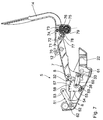
- Fig. 7 shows the locking device 50 in a position in which the Lock bolt 53 in the side view of Figs. 7 and 8 furthest Left illustrated latch receptacle 58 is assigned. In this position is the rear seat support member 7 with the backrest support 14 in the furthest upright position.
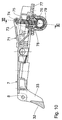
- Fig. 8 shows the locking device 50 in a position in which the Latch bolt 53 of FIGS. 7 and 8 furthest to the right Latch receptacle 58 is assigned. In this position, the rear seat support part 7 with the backrest support 14 furthest back in a lying position inclined.
- the connecting member 60 therefore acts as mechanical translation member, which is the pivoting of the counter body 54 in relation to the pivoting of the rear seat support part. 7 translated.
- the locking device 50 is disabled, so that a synchronous relative movement between the seat support parts 6, 7 allows is. If the user overrides the synchronous mechanism, ie the seat support parts 6, 7 wants to lock against each other, he brings first by appropriate pressure on the backrest 15 and thus on the Backrest support 14 on the rear seat support part 7 latter in one desired relative position to the front seat support part 6. In connection the user actuates the operating handle 63 and moves the locking bolt 53 in the direction of the bolt peripheral portion 57 to.
- the connecting member 60 ensures by its translation function here, that despite the not too small Distance of the bolt receptacles 58 in the circumferential direction of the bolt peripheral portion 57 to each other a fine gradation of discrete relative positions the seat support parts 6, 7 is given.
- Figs. 5 to 8 and Figs. 10 and 11 show details of the seat tilt adjusting device 13.
- the support axis 12 is for this purpose by a first lever arm 70 of a Ne Trentsverstellhebels 71, which is parallel to the pivot axis 8 Swivel axis 72 is pivotable.
- a second lever arm 73 is via a pivot joint with also to the pivot axis 8 parallel Swivel axis 74 a tilt adjustment screw 75 hinged. This is axial slidably and non-rotatably mounted.
- the tilt adjustment screw 75 engages in a tilt adjusting nut 76, which in a lower wall 77 of the rear Seat support part 7 rotatable, but in the direction of the tilt adjustment screw 75 is mounted immovably.
- the tilt adjusting nut 76 has a spur gear Cone section 78 on.
- the two cone sections 78, 79 thus form a straight bevel gear.
- a rotation axis 82 the set screw 75 and a rotation axis 83 of the tilt-actuated rotary handle 81 do not curse with each other, but intersect and enclose a right angle with each other.
- the end portion 80 is in a side wall 84 of a housing 85 which on the rear seat support part 7 is rotatable, but axially to the axis of rotation 83 of the tilt actuation rotary handle 81 immovably stored.
- the free end of the tilt actuation knob 81 is like that of the actuating rotary handle 42 configured as an oval handle 46, so refer to the relevant description of the actuating rotary handle 42 can be.
- a flexible Wave in particular a spring shaft.
- Such flexible waves for Power transmission are known.
- With such a flexible shaft can also a mechanical coupling of the rotational movements of the tilt actuation rotary handle 81 about the axis of rotation 83 on the one hand and the set screw 75 take place about the axis of rotation 82 on the other.
Abstract
Description
Die Erfindung betrifft einen Stuhl, insbesondere einen Bürostuhl, nach dem
Oberbegriff des Anspruchs 1.The invention relates to a chair, in particular an office chair, after
Preamble of
Ein derartiger Stuhl ist aus der DE 43 24 545 A1 bekannt. Bei der bekannten Ausgestaltung handelt es sich um eine sogenannte Synchron-Mechanik, bei der Rückenlehne und Sitz in einem bestimmten vorgegebenen Verhältnis gleichzeitig verschwenkt werden. Zwischen dem vorderen Sitzträgerteil und dem hinteren Sitzträgerteil ist ein Kraftspeicher in Form einer Schrauben-Druckfeder angeordnet, mittels der zwischen dem vorderen Sitzträgerteil und dem hinteren Sitzträgerteil eine Kraft erzeugt wird, welche die Rückenlehne in ihre vordere Endposition und den hinteren Bereich des Sitzes in seine obere Position drückt. Zudem ist eine sogenannte Wipp-Mechanik gegeben, das heißt der Benutzer kann gegen die Rückstellkraft der Rückenlehne mit dem Rücken wippen. Mittels einer Verriegelungseinrichtung kann die Synchron-Mechanik arretiert werden, so dass keine Relativbewegung zwischen den Sitzträgerteilen mehr erfolgen kann. Eine Arretierung beziehungsweise Verriegelung der Synchron-Mechanik erfolgt in Situationen, in denen der Benutzer keine Beweglichkeit der Rückenlehne wünscht. Wenn die Verrieglung in einer aufrechten Position der Rückenlehne erfolgt, kann die daraus sich ergebende Sitzposition vom Benutzer mit der Zeit als unangenehm empfunden werden.Such a chair is known from DE 43 24 545 A1. In the known Embodiment is a so-called synchronous mechanism, at the backrest and seat in a certain predetermined ratio to be pivoted simultaneously. Between the front seat support part and the rear seat support member is a power storage in the form of a helical compression spring arranged, by means of between the front seat support part and the rear seat support member is generated a force which the backrest in its front end position and the rear area of the seat pushes in its upper position. In addition, a so-called seesaw mechanism given, that is, the user can against the restoring force of the backrest bobbing with your back. By means of a locking device The synchronous mechanism can be locked so that there is no relative movement between the seat support parts can be done more. A catch or locking the synchronous mechanism takes place in situations in which the user does not want mobility of the backrest. If the locking is done in an upright position of the backrest, the resulting seating position can be adjusted by the user with the Time to be uncomfortable.
Der Erfindung liegt daher die Aufgabe zugrunde, eine besser an die Bedürfnisse der Benutzer angepasste Verriegelungseinrichtung bei einem Stuhl der eingangs genannten Art zu schaffen. The invention is therefore based on the object, a better to the needs the user adapted locking device at a To create chair of the type mentioned.
Diese Aufgabe ist erfindungsgemäß gelöst durch die im Kennzeichnungsteil
des Anspruchs 1 angegebenen Merkmale.This object is achieved by the in the characterizing part
of
Erfindungsgemäß wurde erkannt, dass es keine bestimmte Relativposition zwischen den Sitzträgerteilen gibt, bei denen die divergierenden Wünsche nach einer bequemen Sitzposition einerseits und einer ausreichenden Unterstützung bei aufrechter Körperposition andererseits bei verriegelter Synchron-Mechanik erfüllt werden können. Die erfindungsgemäße Verriegelungseinrichtung stellt vielmehr eine Mehrzahl diskreter Verriegelungspositionen der Sitzträgerteile zueinander bereit. Es ist daher möglich, die Synchron-Mechanik bei Bedarf in einer relativ aufrechten oder auch in einer im Vergleich hierzu geneigteren Stellung der Rückenlehne zu verriegeln. Natürlich lassen sich auch mehr als zwei Verriegelungspositionen vorgeben. Gegebenenfalls ist auch eine stufenlose Vorgabe von Verriegelungspositionen durch entsprechende Gestaltung der Verriegelungseinrichtung, zum Beispiel durch einen entsprechenden Klemmmechanismus, möglich.According to the invention, it has been recognized that there is no specific relative position between the seat carrier parts, where the divergent wishes for a comfortable sitting position on the one hand and a sufficient support in upright body position on the other hand with locked synchronous mechanism can be met. The locking device according to the invention rather, provides a plurality of discrete locking positions the seat support parts ready for each other. It is therefore possible the Synchronous mechanism if required in a relatively upright or in one compared to lock inclined position of the backrest. Of course, you can also have more than two locking positions pretend. Optionally, a stepless specification of locking positions by appropriate design of the locking device, for example, by a corresponding clamping mechanism, possible.
Eine Verriegelungseinrichtung nach Anspruch 2 lässt sich konstruktiv mit
geringem Aufwand realisieren, wobei die Verriegelungseinrichtung in den
einzelnen diskreten Verriegelungspositionen auch größeren Belastungskräften
standhalten kann. In der Regel sind einige Verriegelungspositionen,
zum Beispiel vier Verriegelungspositionen, ausreichend.A locking device according to
Eine Verriegelungseinrichtung nach Anspruch 3 ist konstruktiv einfach und
trotzdem sicher.A locking device according to
Bei einer Ausgestaltung der Verriegelungseinrichtung nach Anspruch 4 ist
sichergestellt, dass der Riegel und der Gegenkörper bei einer Änderung der
Relativpositionen der Sitzträgerteile vor der Verriegelung ihren Abstand
zueinander nicht wesentlich ändern, so dass der Hub der Verriegelungsbewegung
von der vorgegebenen Relativposition zwischen den Sitzträgerteilen
im Wesentlichen unabhängig ist. Dies erhöht den Bedienkomfort der
Verriegelungseinrichtung.In one embodiment of the locking device according to
Bei einer Verriegelungseinrichtung nach Anspruch 5 ist eine bestimmte
Relativposition zwischen Riegel und Gegenkörper einer Relativposition
zwischen den beiden Sitzträgerteilen eindeutig zugeordnet. Dies erhöht die
Bediensicherheit der Verriegelungseinrichtung. Die Schwenkachse zwischen
den Komponenten der Verriegelungseinrichtung, also dem Gegenkörper
und dem Riegel, kann, muss aber nicht, mit der Schwenkachse zwischen
den beiden Sitzträgerteilen zusammenfallen.In a locking device according to
Wird gemäß Anspruch 6 ein Kupplungselement vorgesehen, lässt sich eine
Übersetzung zwischen den Relativverschwenkungen der Komponenten der
Verriegelungseinrichtung einerseits und den Sitzträgerteilen andererseits
vorgeben. Auch bei relativ weit auseinanderliegend angeordneten
Verriegelungspositionen, was die Verriegelungseinrichtung angeht, können
auf diese Weise fein abgestufte Verriegelungspositionen, was die
Sitzträgerteile angeht, realisiert werden.Is provided according to
Ein Ausführungsbeispiel der Erfindung wird nachfolgend anhand der Zeichnung näher erläutert. Es zeigt
- Fig. 1
- einen Stuhl in perspektivischer Gesamtdarstellung,
- Fig. 2
- eine teilweise geschnittene Draufsicht auf einen Sitzträger des Stuhles nach Fig. 1,
- Fig. 3
- eine zur Fig. 2 ähnliche, unterbrochene und nicht geschnittene Draufsicht auf den Sitzträger,
- Fig. 4
- einen Schnitt gemäß Linie IV-IV in Fig. 2,
- Fig. 5
- einen Schnitt gemäß Linie V-V in Fig. 2 in einer im Vergleich zu Fig. 4 weiter herausgedrehten Position einer Stellschraube,
- Fig. 6
- eine zu Fig. 3 ähnliche Draufsicht auf den Sitzträger, welche einen anderen Abschnitt von diesem zeigt,
- Fig. 7
- einen Schnitt gemäß Linie VII-VII in Fig. 6,
- Fig. 8
- einen zur Fig. 7 ähnlichen Schnitt in einer anderen Relativstellung zweier Sitzträgerteile des Stuhls,
- Fig. 9
- eine zur Fig. 2 ähnliche Draufsicht auf einen Sitzträger eines alternativen Stuhls,
- Fig. 10
- einen Schnitt gemäß Linie X-X in Fig. 9 und
- Fig. 11
- einen Schnitt gemäß Linie XI-XI in Fig. 10.
- Fig. 1
- a chair in perspective overall view,
- Fig. 2
- 1 is a partially sectioned plan view of a seat support of the chair of FIG. 1,
- Fig. 3
- a similar to FIG. 2, broken and not cut plan view of the seat support,
- Fig. 4
- a section along line IV-IV in Fig. 2,
- Fig. 5
- 3 shows a section according to line VV in FIG. 2 in a position of a set screw that is further rotated in comparison to FIG. 4,
- Fig. 6
- 3 is a plan view similar to FIG. 3 of the seat support, showing another portion thereof,
- Fig. 7
- a section along the line VII-VII in Fig. 6,
- Fig. 8
- 7 similar section in another relative position of two seat support parts of the chair,
- Fig. 9
- 2 similar to a plan view of a seat support of an alternative chair,
- Fig. 10
- a section along line XX in Fig. 9 and
- Fig. 11
- a section along line XI-XI in Fig. 10.
Fig. 1 zeigt einen Bürostuhl mit einem Stuhlgestell 1. Dieses ist mit einem
Fußgestell 2 versehen, welches sich über Laufrollen 3 gegenüber dem Boden
abstützt. Auf dem Fußgestell 2 ist eine höhenverstellbare Stuhlsäule 4
angebracht, an derem oberen Ende ein Sitzträger 5 befestigt ist. Letzterer
ist zweiteilig ausgestaltet; er weist einen vorderen Sitzträgerteil 6, der auf
der Stuhlsäule 4 befestigt ist, und einen hinteren Sitzträgerteil 7 auf, der
oberhalb der Stuhlsäule 4 mittels eines um eine Schwenkachse 8 drehbaren
Schwenkgelenks am vorderen Sitzträgerteil 6 angelenkt ist. Im vorderen
Bereich des vorderen Sitzträgerteils 6 ist ein Tragrohr 9 befestigt, das parallel
zur Schwenkachse 8 verläuft. Auf diesem Tragrohr 9 stützt sich ein
Sitz 10 kurz hinter seiner Vorderkante 11 ab. Das Tragrohr 9 stellt daher
einen vorderen Auflageabschnitt für den Sitz 10 dar. Der Sitz 10 stützt sich
in seinem hinteren Bereich auf eine Stützachse 12 ab, die im hinteren Sitzträgerteil
7 gelagert ist. Die Stützachse 12 stellt daher einen hinteren Auflageabschnitt
für den Sitz 10 dar. Am hinteren Sitzträgerteil 7 ist weiterhin
eine Sitzneigungs-Verstelleinrichtung 13 angeordnet.Fig. 1 shows an office chair with a
Einstückig mit dem hinteren Sitzträgerteil 7 ist ein von diesem hochragender
Rückenlehnen-Träger 14 ausgebildet, auf dem eine Rückenlehne 15
angebracht ist. Um deren Höhe relativ zum Sitz 10 verstellen zu können, ist
eine Rückenlehnen-Höhenverstelleinrichtung 16 vorgesehen.Integral with the rear
Die geschilderte Ausgestaltung des Sitzträgers 5 mit der Anordnung des
Sitzes 10 und der Rückenlehne 15 bildet eine sogenannte Synchron-Mechanik.
Um die bei einem Verstellen oder beim Wippen durch einen
Benutzer zu überwindenden Kräfte verändern zu können, ist eine insgesamt
mit 17 bezeichnete Kraftveränderungs-Einrichtung vorgesehen, die noch
im Einzelnen erläutert wird. Teil der Kraftveränderungs-Einrichtung 17 ist
eine über den vorderen Sitzträgerteil 6 nach unten überstehende Stellmutter
18, von der in Fig. 1 eine frei drehbare Abdeckkappe 19 sichtbar ist. The described embodiment of the
Benachbart zur Vorderkante 11 des Sitzes 10 auf den äußeren Enden des
Tragrohrs 9 sind Armlehnen 20 angebracht. Von diesen ist in der Seitenansicht
der Fig. 1 nur eine erkennbar.Adjacent to the leading
Die Stuhlsäule 4 weist zur Höhenverstellung des Sitzträgers 5 mit dem Sitz
10 und der Rückenlehne 15 eine bekannte längenverstellbare Gasfeder 21
auf, die in Fig. 3 in Aufsicht dargestellt ist. Die Gasfeder 21 ist in einer als
Konus ausgebildeten Klemmeinrichtung 22 des vorderen Sitzträgerteils 6
klemmend gehalten. Aus der Gasfeder 21 ragt nach oben ein Ventilbetätigungsstift
23 heraus, bei dessen Einschieben in die Gasfeder 21 ein dort
vorhandenes Ventil geöffnet wird, wodurch Längenverstellungen der Gasfeder
21 möglich werden. Derartige Gasfedern sind beispielsweise in der
DE 18 12 282 C2 (entspricht US-Patent 3,656,593) dargestellt und beschrieben.
Zur Betätigung des Ventilbetätigungsstifts 23 ist ein zweiarmiger
Ventilbetätigungs-Hebel 24 vorgesehen, der sich schwenkbar gegen die
Schwenkachse 8 abstützt, wie zum Beispiel in der DE 43 24 545 A1 beschrieben
ist. Ein erster Hebelarm 25 des Ventil-Betätigungshebels 24 liegt
gegen den Ventilbetätigungsstift 23 an, während der zweite Hebelarm 26
über eine aus der DE 43 24 545 A 1 bekannte Hebelmechanik betätigt werden
kann.The
Einer Verschwenkung des hinteren Sitzträgerteils 7 relativ zum vorderen
Sitzträgerteil 6 der Synchron-Mechanik wirkt ein Kraftspeicher 27 entgegen,
bei dem es sich im dargestellten Ausführungsbeispiel um eine vorgespannte
Schrauben-Druckfeder 28 handelt. Diese stützt sich über ein insbesondere
in den Fig. 2 und 5 dargestelltes schwenkbares Widerlager 29 gegen
den vorderen Sitzträgerteil 6 in einem der Vorderkante 11 des Sitzes
10 benachbarten Bereich von diesem ab. Hierzu weist der Kraftspeicher 27
eine die Schrauben-Druckfeder 28 durchsetzende Führungsstange 30 auf. A pivoting of the rear
Mit ihrem anderen Ende stützt sich die Schrauben-Druckfeder 28 gegen
einen Gleitschuh 31 der Kraftveränderungs-Einrichtung 17 ab. Der Gleitschuh
31 wiederum liegt gegen eine Gleitfläche 32 an, die an einem ersten,
kurzen Hebelarm 33 des hinteren Sitzträgerteils 7 ausgebildet ist. Der Hebelarm
33 ist einstückig mit dem hinteren Sitzträgerteil 7 ausgebildet und
verläuft von der Schwenkachse 8 aus im Wesentlichen nach unten. Geometrisch
ist insofern der hintere Sitzträgerteil 7 als Winkelhebel ausgebildet.
Auf der Führungsstange 30 ist der Gleitschuh 31 längs der Schrauben-Druckfeder
28 verschiebbar. An einem dem Widerlager 29 entgegengesetzten
Stellabschnitt 34 der Führungsstange 30 greift die Kraftveränderungs-Einrichtung
17 an. Ein sich an den Stellabschnitt 34 anschließender Verbindungsabschnitt
35 der Führungsstange 30 durchsetzt den ersten Hebelarm
33 des hinteren Sitzträgerteils 7. Gegenüber dem die Schrauben-Druckfeder
28 durchsetzenden Abschnitt der Führungsstange 30 ist der
Verbindungsabschnitt 35 in Richtung auf das hintere Sitzträgerteil 7 zu
abgewinkelt. Der Stellabschnitt 34 der Führungsstange 30 ist daher auf den
hinteren Sitzträgerteil 7 zu abgekröpft und dem Sitzträger 5 benachbart
angeordnet.With its other end, the
Teil der Kraftveränderungs-Einrichtung 17 ist eine Stellschraube 36, die
am Stellabschnitt 34 der Führungsstange 30 über ein Schwenkgelenk mit
Schwenkachse 37 schwenkbar angelenkt ist.Part of the
Der Abstand zwischen der Schwenkachse 8 zwischen den Sitzträgerteilen
6, 7 einerseits und der Mittelachse der Schrauben-Druckfeder 28 andererseits
ist in Fig. 5 mit a bezeichnet.The distance between the
Die Stellschraube 36 greift in die Stellmutter 18 ein, die in einer unteren
Wand 38 des vorderen Sitzträgerteils 6 drehbar, aber in Richtung der Stellschraube
36 unverschiebbar gelagert ist. Am der Abdeckkappe 19 gegenüberliegenden
Ende weist die Stellmutter 18 einen geradverzahnten Kegelabschnitt
39 auf. In den Zahnkranz von diesem greift ein ebenfalls geradverzahnter
Kegelabschnitt 40 eines Endabschnitts 41 eines Betätigungs-Drehgriffs
42 ein. Die beiden Kegelabschnitte 39, 40 bilden somit ein geradverzahntes
Kegelradgetriebe. Eine Drehachse 43 der Stellschraube 36
und eine Drehachse 44 des Betätigungs-Drehgriffs 42 fluchten nicht miteinander,
sondern schneiden sich und schließen miteinander einen rechten
Winkel ein. Der Endabschnitt 41 ist in einer Seitenwand 45 des vorderen
Sitzträgerteils 6 drehbar, aber axial zur Drehachse 44 des Betätigungs-Drehgriffs
42 unverschiebbar gelagert.The adjusting
Das freie Ende des Betätigungs-Drehgriffs 42 ist als ovaler Handgriff 46
mit Griffmulden 47 ausgebildet. Der Handgriff 46 weist eine zentrale Bohrung
48 auf, die am freien Ende des Handgriffs 46 durch eine eingedrückte
Verschlusskappe 49 verschlossen ist. In die Bohrung eingeführt ist eine
Verbindungsschraube 50, welche den Handgriff 46 am Endabschnitt 41 des
Betätigungs-Drehgriffs 42 haltert.The free end of the actuating
Bei einer Drehung des Betätigungs-Drehgriffs 42 wird diese Drehung über
die ineinandergreifenden Kegelabschnitte 39, 40 in eine axiale Stellbewegung
der Stellschraube 36 längs der Drehachse 43 überführt. Die Kegelabschnitte
39, 40 stellen daher ein Kupplungs-Element dar, über welches der
Betätigungs-Drehgriff 42 mit der Stellschraube 36 als Stell-Element verbunden
ist. Bei einer Drehung des Betätigungs-Drehgriffs 42 wird daher
über das Schwenkgelenk mit der Schwenkachse 37 die Führungsstange 30
um das Schwenkgelenk des Widerlagers 29 verschwenkt. Der Gleitschuh
31 wird hierbei auf der Gleitfläche 32 des ersten Hebelarms 33 verschoben,
wodurch sich der Abstand a der Achse des Kraftspeichers 27 von der
Schwenkachse 8 ändert. Da die Gleitfläche 32 zumindest angenähert auf
einem Kreisbogenabschnitt liegt, dessen Mittelpunkt oberhalb der Achse
des Schwenkgelenks des Wiederlagers 29 gebildet wird, ändert sich bei
einer Verdrehung des Betätigungs-Drehgriffs 42 ein Abstand b zwischen
der Schwenkachse des Widerlagers 29 und der Durchdringung der Achse
des Kraftspeichers 27 durch die Gleitfläche 32 nur gering. Daher ändert
sich bei derartigen Verstellungen die Vorspannung der Schrauben-Druckfeder
28 praktisch nicht. Durch die oben beschriebene leichte Dezentrierung
der Gleitfläche 32 zum durch das Widerlager 29 gebildeten
Schwenkgelenk wird erreicht, dass an der Stellschraube 36 immer eine
durch die Schrauben-Druckfeder 28 vermittelte Zugkraft anliegt. Dies führt
dazu, dass die Stellschraube 36 in der Stellmutter 18 immer definiert derart
geführt ist, dass die in Fig. 5 obenliegenden Gewindeflanken des Gewindes
der Stellschraube 36 an den entsprechenden Gewindeflanken des Innengewindes
der Stellmutter 18 anliegen.Upon rotation of the actuating
Die von der Schrauben-Druckfeder 28 auf den ersten Hebelarm 33 des hinteren
Sitzträgerteils 7 wirkende Kraft wird also nicht verändert; es wird
lediglich durch Veränderung des Abstands a zwischen der Achse des
Kraftspeichers 27 und der Schwenkachse 8 der wirksame Hebelarm, das
heißt insgesamt das von der Schrauben-Druckfeder 28 auf den hinteren
Sitzträgerteil 7 und damit auf den Sitz 10 und die Rückenlehne 15 wirkende
Drehmoment, verändert. Dieses Drehmoment wird umso kleiner, je kleiner
der Abstand a ist und umgekehrt. Die am Betätigungs-Drehgriff 42
aufzubringenden Verstellkräfte über den gesamten Verstellweg des Gleitschuhs
31 können konstant gehalten werden, da sich Reibungskräfte zwischen
dem Gleitschuh 31 und der Gleitfläche 32 und auch die Betätigungskräfte
der mechanischen Kupplung zwischen der Führungsstange 30 und
dem Betätigungs-Drehgriff 42 praktisch nicht ändern. The of the
Um die gemeinsame Verschwenkbarkeit des Sitzes 10 und der Rückenlehne
15 bei der Synchro-Mechanik gegen die Kraft der Schrauben-Druckfeder
28 ausschalten zu können, ist eine in den Fig. 6 bis 8 dargestellte
Verriegelungseinrichtung 50 vorgesehen. Die Verriegelungseinrichtung
50 umfasst einen Riegel 51, der am vorderen Sitzträgerteil 6 um ein
Schwenkgelenk mit Schwenkachse 52 verschwenkbar angelenkt ist. Die
Schwenkachse 52 fällt mit derjenigen des Widerlagers 29 im Wesentlichen
zusammen. An seinem freien, von der Schwenkachse 52 abgewandten Ende
weist der Riegel 51 einen horizontal angeordneten Riegelbolzen 53 auf,
der am Riegel 51 festgelegt ist und diesen derart durchtritt, dass er zu beiden
Seiten über den Riegel 51 in horizontaler Richtung übersteht.To the joint pivoting of the
Teil der Verriegelungseinrichtung 50 ist ein mit dem Riegel 51 zusammenarbeitender
Gegenkörper 54. Dieser ist am vorderen Sitzträgerteil 6 um ein
Schwenkgelenk mit Schwenkachse 55 verschwenkbar angelenkt. Die
Schwenkachsen 52, 55 sind zueinander beabstandet und parallel. Der Gegenkörper
54 weist zwei zueinander beabstandete, parallele, vertikale und
senkrecht zur Schwenkachse 55 angeordnete Platten 56 auf. Diese haben in
grober Näherung eine dreiecksförmige Gestalt, wobei die der Schwenkachse
55 gegenüberliegende Seite als Riegel-Umfangsabschnitt 57 angenähert
auf einen Kreisbogenabschnitt liegt, dessen Mittelpunkt durch die
Schwenkachse 55 gebildet wird.Part of the
Im Riegel-Umfangsabschnitt 57 der Platten 56 sind jeweils vier im Wesentlichen
halbkreisförmige Riegelaufnahmen 58 ausgebildet, wobei jeweils
zwei Riegelaufnahmen in je einer der Platten 56 paarweise miteinander
fluchten. Die Weite der Riegelaufnahmen 58 ist komplementär zum
Riegelbolzen 53 des Riegels 51 derart bemessen, dass der Riegelbolzen 53
im Wesentlichen spielfrei in ein Paar von Riegelaufnahmen 58 eingreifen
kann. Dieser Eingriff des Riegelbolzens 53 in die Riegelaufnahmen 58 erfolgt
derart, dass jeweils eines der beiden freien Enden des Riegelbolzens
53 in eine der beiden Riegelaufnahmen 58 des entsprechenden Paares von
Riegelaufnahmen 58 eingreift.In the latch
Über ein Schwenkgelenk mit Schwenkachse 59 ist am Gegenkörper 54 als
Kupplungselement ein Verbindungsglied 60 angelenkt. Die Schwenkachsen
55 und 59 sind zueinander beabstandet und parallel. Über ein weiteres
Schwenkgelenk mit Schwenkachse 61 ist das Verbindungsglied 60 am ersten,
kurzen Hebelarm 33 des hinteren Sitzträgerteils 7 angelenkt. Die
Schwenkachse 61 ist hierbei zu den Schwenkachsen 8 und 59 parallel und
zu diesen beabstandet.About a pivot joint with
Über einen Kupplungsbolzen 62, der mittels eines Auflagebocks am vorderen
Sitzträgerteil 6 befestigt ist, kann der Riegel 51 mittels eines seitlich
aus dem Tragrohr 9 herausgeführten Betätigungsgriff 63 betätigt werden,
der in Fig. 1 dargestellt ist.Via a
Fig. 7 zeigt die Verriegelungseinrichtung 50 in einer Stellung, bei der der
Riegelbolzen 53 der in der Seitenansicht der Fig. 7 und 8 am weitesten
links dargestellten Riegelaufnahme 58 zugeordnet ist. In dieser Stellung ist
der hintere Sitzträgerteil 7 mit dem Rückenlehnen-Träger 14 in der am weitesten
aufrechten Position.Fig. 7 shows the
Fig. 8 zeigt die Verriegelungseinrichtung 50 in einer Stellung, bei der der
Riegelbolzen 53 der in den Fig. 7 und 8 am weitesten rechts dargestellten
Riegelaufnahme 58 zugeordnet ist. In dieser Stellung ist der hintere Sitzträgerteil
7 mit dem Rückenlehnen-Träger 14 am weitesten nach hinten in
eine Liegeposition geneigt.Fig. 8 shows the
Da der Abstand zwischen den Schwenkachsen 8 und 61 größer ist als derjenige
zwischen den Schwenkachsen 55 und 59, führt eine Verschwenkung
des hinteren Sitzträgerteils 7 um die Schwenkachse 8 zu einer im Verhältnis
dieser Abstände zueinander größeren Verschwenkung des Gegenkörpers
54 um die Schwenkachse 55. Das Verbindungsglied 60 wirkt daher als
mechanisches Übersetzungsglied, welches die Verschwenkung des Gegenkörpers
54 im Verhältnis zur Verschwenkung des hinteren Sitzträgerteils 7
übersetzt.Since the distance between the pivot axes 8 and 61 is greater than that
between the pivot axes 55 and 59, performs a pivoting
the rear
Im Normalfall ist die Verriegelungseinrichtung 50 außer Funktion, so dass
eine Synchron-Relativbewegung zwischen den Sitzträgerteilen 6, 7 ermöglicht
ist. Wenn der Benutzer die Synchron-Mechanik außer Kraft setzt, also
die Sitzträgerteile 6, 7 gegeneinander verriegeln will, bringt er zunächst
durch entsprechenden Druck auf die Rückenlehne 15 und damit über den
Rückenlehnen-Träger 14 auf das hintere Sitzträgerteil 7 letzteres in eine
gewünschte Relativposition zum vorderen Sitzträgerteil 6. In Anschluss
daran betätigt der Benutzer den Betätigungsgriff 63 und bewegt den Riegelbolzen
53 in Richtung auf den Riegel-Umfangsabschnitt 57 zu. Der
Riegelbolzen 53 kommt dann entweder sofort mit der ihm benachbarten
Riegelaufnahme 58 in Eingriff oder der Benutzer führt noch eine Feinverstellung
der Sitzträgerteile 6, 7 zueinander durch entsprechenden Druck
auf die Rückenlehne 15 durch, bis der Riegelbolzen 53 in das entsprechende
Paar von Riegelaufnahmen 58 einrückt. Sobald dies geschehen ist, ist
die Synchron-Mechanik in der gewünschten Relativposition der Sitzträgerteile
6, 7 zueinander verriegelt. Das Verbindungsglied 60 gewährleistet
durch seine Übersetzungsfunktion hierbei, dass trotz des nicht zu geringen
Abstandes der Riegelaufnahmen 58 in Umfangsrichtung des Riegel-Umfangsabschnitts
57 zueinander eine feine Abstufung diskreter Relativpositionen
der Sitzträgerteile 6, 7 gegeben ist.Normally, the locking
Fig. 5 bis 8 sowie 10 und 11 zeigen Details der Sitzneigungs-Verstelleinrichtung
13. Zur Sitzneigungs-Verstellung ist die Höhe der Stützachse 12,
auf der sich der hintere Bereich des Sitzes abstützt, verstellbar. Die Stützachse
12 wird hierzu von einem ersten Hebelarm 70 eines Neigungsverstellhebels
71 getragen, der um eine zur Schwenkachse 8 parallele
Schwenkachse 72 verschwenkbar ist. An einem zweiten Hebelarm 73 ist
über ein Schwenkgelenk mit ebenfalls zur Schwenkachse 8 paralleler
Schwenkachse 74 eine Neigungs-Stellschraube 75 angelenkt. Diese ist axial
verschiebbar und drehfest gelagert. Die Neigungs-Stellschraube 75 greift
in eine Neigungs-Stellmutter 76 ein, die in einer unteren Wand 77 des hinteren
Sitzträgerteils 7 drehbar, aber in Richtung der Neigungs-Stellschraube
75 unverschiebbar gelagert ist. Am der Schwenkachse 74 gegenüberliegenden
Ende weist die Neigungs-Stellmutter 76 einen geradverzahnten
Kegelabschnitt 78 auf. In den Zahnkranz von diesem greift ein ebenfalls
geradverzahnter Kegelabschnitt 79 eines Endabschnitts 80 eines
Neigungs-Betätigungs-Drehgriffs 81 ein. Die beiden Kegelabschnitte 78,
79 bilden somit ein geradverzahntes Kegelradgetriebe. Eine Drehachse 82
der Stellschraube 75 und eine Drehachse 83 des Neigungs-Betätigungs-Drehgriffs
81 fluchten nicht miteinander, sondern schneiden sich und
schließen miteinander einen rechten Winkel ein. Die Drehachsen 44 und 83
der Betätigungs-Drehgriffe 42 und 81, die auf der gleichen Seite über den
Sitzträger 5 überstehen, sind zueinander parallel. Der Endabschnitt 80 ist in
einer Seitenwand 84 eines Gehäuses 85, welches am hinteren Sitzträgerteil
7 befestigt ist, drehbar, aber axial zur Drehachse 83 des Neigungs-Betätigungs-Drehgriffs
81 unverschiebbar gelagert. Figs. 5 to 8 and Figs. 10 and 11 show details of the seat tilt adjusting device
13. For seat tilt adjustment, the height of the
Das freie Ende des Neigungs-Betätigungs-Drehgriffs 81 ist wie dasjenige
des Betätigungs-Drehgriffs 42 als ovaler Handgriff 46 ausgestaltet, sodass
auf die diesbezügliche Beschreibung des Betätigungs-Drehgriffs 42 verwiesen
werden kann.The free end of the
Bei einer Drehung des Neigungs-Betätigungs-Drehgriffs 81 wird diese
Drehung über die ineinandergreifenden Kegelabschnitte 78, 79 in eine axiale
Stellbewegung der Stellschraube 75 längs der Drehachse 82 überführt.
Die Kegelabschnitte 78, 79 stellen daher ein Kupplungselement dar, über
welches der Neigungs-Betätigungs-Drehgriff 81 mit der Stellschraube 75
als Stell-Element verbunden ist. Bei einer Drehung des Neigungs-Betätigungs-Drehgriffs
81 wird daher über das Schwenkgelenk mit der
Schwenkachse 74 der Neigungs-Verstellhebel 71 um die Schwenkachse 72
verschwenkt. Hierdurch wird die Höhe der Stützachse 12 über dem Boden
und damit die Neigung des Sitzes 10 eingestellt. Je höher die Stützachse 12
eingestellt ist, desto stärker ist der Sitz 10 in Richtung seiner Vorderkante
11 nach unten geneigt.Upon rotation of the tilt-operation rotary handle 81, this becomes
Rotation over the
Bei einer nicht dargestellten weiteren Ausführungsform erfolgt eine mechanische
Kupplung der Drehbewegungen des Betätigungs-Drehgriffs 42
um die Drehachse 44 einerseits und der Stellschraube 36 um die Drehachse
43 andererseits nicht durch ein Kegelradgetriebe, sondern durch eine flexible
Welle, insbesondere eine Feder-Welle. Derartige flexible Wellen zur
Kraftübertragung sind bekannt. Mit einer solchen flexiblen Welle kann
auch eine mechanische Kupplung der Drehbewegungen des Neigungs-Betätigungs-Drehgriffs
81 um die Drehachse 83 einerseits und der Stellschraube
75 um die Drehachse 82 andererseits erfolgen.In a further embodiment, not shown, a mechanical
Coupling the rotational movements of the actuating rotary handle 42
about the axis of
Claims (6)
dadurch gekennzeichnet, dass
characterized in that
Priority Applications (1)
| Application Number | Priority Date | Filing Date | Title |
|---|---|---|---|
| PL04004811T PL1454568T3 (en) | 2003-03-07 | 2004-03-02 | Chair, particularly office-chair |
Applications Claiming Priority (4)
| Application Number | Priority Date | Filing Date | Title |
|---|---|---|---|
| DE10309922A DE10309922A1 (en) | 2003-03-07 | 2003-03-07 | Chair, especially office chair |
| DE10309920 | 2003-03-07 | ||
| DE10309920A DE10309920A1 (en) | 2003-03-07 | 2003-03-07 | Chair, especially office chair |
| DE10309921A DE10309921A1 (en) | 2003-03-07 | 2003-03-07 | Chair, especially office chair |
Publications (3)
| Publication Number | Publication Date |
|---|---|
| EP1454568A2 true EP1454568A2 (en) | 2004-09-08 |
| EP1454568A3 EP1454568A3 (en) | 2005-01-19 |
| EP1454568B1 EP1454568B1 (en) | 2008-07-02 |
Family
ID=42315213
Family Applications (3)
| Application Number | Title | Priority Date | Filing Date |
|---|---|---|---|
| EP04004813A Expired - Lifetime EP1454569B1 (en) | 2003-03-07 | 2004-03-02 | Chair, in particular an office chair |
| EP04004811A Expired - Lifetime EP1454568B1 (en) | 2003-03-07 | 2004-03-02 | Chair, particularly office-chair |
| EP04004812A Expired - Lifetime EP1454566B1 (en) | 2003-03-07 | 2004-03-02 | Chair, particularly office chair |
Family Applications Before (1)
| Application Number | Title | Priority Date | Filing Date |
|---|---|---|---|
| EP04004813A Expired - Lifetime EP1454569B1 (en) | 2003-03-07 | 2004-03-02 | Chair, in particular an office chair |
Family Applications After (1)
| Application Number | Title | Priority Date | Filing Date |
|---|---|---|---|
| EP04004812A Expired - Lifetime EP1454566B1 (en) | 2003-03-07 | 2004-03-02 | Chair, particularly office chair |
Country Status (10)
| Country | Link |
|---|---|
| US (3) | US6945603B2 (en) |
| EP (3) | EP1454569B1 (en) |
| CN (3) | CN100486483C (en) |
| AT (3) | ATE399490T1 (en) |
| DE (6) | DE10309920A1 (en) |
| DK (3) | DK1454569T3 (en) |
| ES (3) | ES2255691T3 (en) |
| HK (2) | HK1069296A1 (en) |
| PL (2) | PL1454566T3 (en) |
| ZA (3) | ZA200401855B (en) |
Families Citing this family (43)
| Publication number | Priority date | Publication date | Assignee | Title |
|---|---|---|---|---|
| NO317791B1 (en) * | 2002-01-04 | 2004-12-13 | Stokke As | Moving joints |
| ITVE20030014A1 (en) * | 2003-04-10 | 2004-10-11 | Imarc Spa | DEVICE FOR ADJUSTING THE PRELOAD DEGREE OF THE SPRINGS IN MECHANISMS OF OFFICE CHAIRS. |
| US7500718B2 (en) * | 2004-05-14 | 2009-03-10 | Haworth, Inc. | Tilt tension mechanism for chair |
| US20060220431A1 (en) * | 2005-03-17 | 2006-10-05 | Kwa Ing C | Chair control device |
| US7261368B1 (en) * | 2006-02-27 | 2007-08-28 | Todd Clausnitzer | Ergonomic chair |
| WO2007110732A2 (en) * | 2006-03-24 | 2007-10-04 | Herman Miller Inc. | Piece of furniture |
| WO2007124609A2 (en) * | 2006-04-27 | 2007-11-08 | Vitra Patente Ag | Mechanism for a chair |
| DE102006023981A1 (en) * | 2006-05-22 | 2007-12-06 | Wilkhahn Wilkening + Hahne Gmbh & Co. Kg | chair |
| DE102006023982A1 (en) * | 2006-05-22 | 2007-12-06 | Wilkhahn Wilkening + Hahne Gmbh & Co. Kg | chair |
| US20070290537A1 (en) * | 2006-06-13 | 2007-12-20 | Tung Yu Oa Co., Ltd. | Recliner |
| US7922630B1 (en) * | 2006-06-15 | 2011-04-12 | Roger Batca | Adjustable bicep curl support pads |
| DE102006049676B4 (en) * | 2006-10-18 | 2008-12-11 | Sedus Stoll Ag | Chair with tilting seat |
| DE502007002330D1 (en) * | 2007-01-22 | 2010-01-28 | Stoll Sedus Ag | Chair with tilting seat |
| CN102151027B (en) | 2007-01-29 | 2016-03-16 | 赫尔曼米勒有限公司 | Seat structure and using method thereof |
| ITMI20070718A1 (en) * | 2007-04-06 | 2008-10-07 | L & P Property Management Co | ADJUSTMENT DEVICE FOR ADJUSTABLE AND SIMILAR CHAIRS. |
| ITMI20070719A1 (en) * | 2007-04-06 | 2008-10-07 | L & P Property Management Co | TILTING DEVICE FOR A RECLINING SEAT. |
| US7467826B1 (en) * | 2007-08-14 | 2008-12-23 | Hurng Taih Plastic Master Batch Co., Ltd. | Resilience tilt-adjusted device of backrest |
| US8015981B2 (en) * | 2007-08-19 | 2011-09-13 | Anastasia Soare | Stencils and gauging device for aesthetically pleasing eyebrow shaping |
| BRPI0817111A2 (en) * | 2007-09-20 | 2015-03-31 | Miller Herman Inc | BODY SUPPORT STRUCTURE |
| DE602007012944D1 (en) * | 2007-10-30 | 2011-04-14 | Donati Spa | MECHANISM FOR ADJUSTING THE PRELOAD OF A SEAT HEATING SPRING |
| AU2008341014B2 (en) * | 2007-12-20 | 2016-05-19 | Comfort Concepts Pty Limited | Seating systems incorporating self-inflating adjustable supports |
| US7530637B1 (en) * | 2008-03-18 | 2009-05-12 | Yao-Chuan Wu | Chair assembly |
| EP2375938B2 (en) * | 2009-02-25 | 2020-01-08 | Donati S.p.A. | Device for synchronizing the tilt of a chair back and seat |
| ES2333768B1 (en) * | 2009-07-21 | 2010-10-13 | Actiu Berbegal Y Formas, S.A. | OFFICE CHAIR. |
| KR101009490B1 (en) * | 2010-04-28 | 2011-01-21 | 주식회사 토치 | A chair comprised seat plate moving structure |
| US9962307B2 (en) | 2010-12-20 | 2018-05-08 | Restoration Robotics, Inc. | Adjustable hair transplantation chair |
| US9277821B2 (en) | 2011-07-01 | 2016-03-08 | L&P Property Management Company | Tilt mechanism for a chair and chair |
| TW201311188A (en) * | 2011-07-15 | 2013-03-16 | Itoki Corp | Rocking chair and spring unit used therefor |
| DE202012002288U1 (en) * | 2012-03-08 | 2012-05-11 | Walter Knoll Ag & Co. Kg | functional chair |
| CN102846067B (en) * | 2012-09-18 | 2014-10-15 | 浙江永艺家具股份有限公司 | Back locking mechanism for swivel chair |
| USD697726S1 (en) | 2012-09-20 | 2014-01-21 | Steelcase Inc. | Chair |
| US11304528B2 (en) | 2012-09-20 | 2022-04-19 | Steelcase Inc. | Chair assembly with upholstery covering |
| CN104661567B (en) * | 2012-09-20 | 2018-07-13 | 斯迪尔科斯公司 | Chair arm component |
| NO335007B1 (en) * | 2012-12-19 | 2014-08-25 | Scandinavian Business Seating AS | Device for tilting chair for chair |
| US8939509B2 (en) * | 2013-04-11 | 2015-01-27 | Hangzhou Zhongtai Industrial Group Co., Ltd. | Chair chassis |
| CN103330403B (en) * | 2013-07-19 | 2016-02-10 | 湖州奥圣家具有限公司 | A kind of adjusting device of swivel chair |
| CN103330404B (en) * | 2013-07-19 | 2016-06-08 | 湖州奥圣家具有限公司 | A kind of swivel chair being provided with multifunctional regulation device |
| CN105266431B (en) * | 2014-06-02 | 2018-06-22 | 大河精工有限公司 | Chair assembly |
| DE102016104638A1 (en) * | 2016-03-14 | 2017-09-14 | Burkhard Schmitz | chair |
| CN106617848A (en) * | 2016-11-08 | 2017-05-10 | 安吉恒林科技发展有限公司 | Chair inclination adjusting device and chair provided with same |
| FI128663B (en) * | 2018-10-31 | 2020-09-30 | Easydoing Oy | A bridge support device for a saddle chair with a divided seat |
| US11246417B2 (en) * | 2019-08-07 | 2022-02-15 | Chen Raizman | Tilt-swivel mechanism chair |
| CN113729426A (en) * | 2021-05-27 | 2021-12-03 | 广东联友办公家具有限公司 | Seat chassis and seat |
Citations (5)
| Publication number | Priority date | Publication date | Assignee | Title |
|---|---|---|---|---|
| US5294178A (en) * | 1990-12-13 | 1994-03-15 | Christof Stoll Gmbh + Co Kg | Tilt device for seat furniture |
| DE4324543A1 (en) * | 1993-07-22 | 1995-01-26 | Trendoffice Bueromoebel | Chair, in particular office chair |
| US5813726A (en) * | 1997-02-18 | 1998-09-29 | Hoover Universal, Inc. | Inertia locking device for a vehicle seat adjustment mechanism |
| EP1057429A1 (en) * | 1999-06-04 | 2000-12-06 | PRO-CORD s.r.l. | "Chair with synchronized tilting seat and back" |
| US20020113475A1 (en) * | 1995-06-07 | 2002-08-22 | Herman Miller, Inc. | Method for adjusting a seat |
Family Cites Families (29)
| Publication number | Priority date | Publication date | Assignee | Title |
|---|---|---|---|---|
| DE23360C (en) * | E. CALIX in Zürich, Schweiz | Mechanism for adjusting chairs and tables in the vertical direction | ||
| US1730252A (en) * | 1927-04-25 | 1929-10-01 | Adjustable piajsto ok obgast bektch | |
| US2015138A (en) * | 1934-02-17 | 1935-09-24 | Benjamin H Drake | Chair |
| US2272980A (en) * | 1939-02-11 | 1942-02-10 | Mclellan | Chair construction |
| US2224543A (en) * | 1939-03-22 | 1940-12-10 | Frank B Harman | Swivel chair |
| DE1812282C3 (en) * | 1968-12-03 | 1981-07-30 | Fritz Bauer + Söhne oHG, 8503 Altdorf | Lifting device for stepless height adjustment of table tops, chair seats and the like. |
| DE3467498D1 (en) * | 1983-08-09 | 1987-12-23 | Pledge Office Chairs | Tilting mechanism for a chair |
| US4652050A (en) * | 1984-01-11 | 1987-03-24 | Herman Miller, Inc. | Chair tilt mechanism |
| DE8401000U1 (en) * | 1984-01-14 | 1984-04-05 | Mauser Waldeck AG, 3544 Waldeck | SWIVEL CHAIR |
| CH668541A5 (en) * | 1986-01-07 | 1989-01-13 | Provenda Marketing Ag | WORK CHAIR, ESPECIALLY FOR USE AS OFFICE CHAIR. |
| US4709963A (en) * | 1986-12-12 | 1987-12-01 | Milsco Manufacturing Company | Adjustable office chair |
| JPH0511791Y2 (en) * | 1987-08-24 | 1993-03-24 | ||
| DE3741472A1 (en) * | 1987-12-08 | 1989-06-22 | Simon Desanta | CHAIR |
| US5106157A (en) * | 1989-03-01 | 1992-04-21 | Herman Miller, Inc. | Chair height and tilt adjustment mechanisms |
| JPH0716457B2 (en) * | 1991-06-26 | 1995-03-01 | 株式会社岡村製作所 | Chair backrest tilt cushion |
| IL103477A0 (en) * | 1992-10-20 | 1993-03-15 | Paltechnica Nitzanim | Office and like chairs |
| US5556163A (en) * | 1994-08-17 | 1996-09-17 | Eac Corporation | Automatically adjustable office and task chairs |
| DE4436145A1 (en) * | 1994-10-11 | 1996-04-18 | Kusch Co Sitzmoebel | Seating |
| US5725276A (en) * | 1995-06-07 | 1998-03-10 | Ginat; Jonathan | Tilt back chair and control |
| ATE223170T1 (en) * | 1996-10-14 | 2002-09-15 | Vitra Patente Ag | CHAIR MECHANICS |
| TW414040U (en) * | 1997-09-10 | 2000-12-01 | Takano Co Ltd | Device for tilting, swaying and fastening |
| US6250715B1 (en) * | 1998-01-21 | 2001-06-26 | Herman Miller, Inc. | Chair |
| WO2000022959A1 (en) * | 1998-10-20 | 2000-04-27 | Protoned B.V. | Chair mechanism |
| DE19922446B8 (en) * | 1999-05-07 | 2009-02-19 | Bock-1 Gmbh & Co. | Synchronous mechanism for a correlated seat-backrest movement of an office chair |
| DE20004361U1 (en) * | 2000-03-10 | 2001-04-12 | Froli Kunststoffwerk Fromme H | Seat for a standing aid or for an office or workshop chair |
| NZ515698A (en) * | 2000-05-22 | 2003-03-28 | Miller Herman Inc | Office chair characterised by pivotal and slidable members for restricting forward and rearward movements |
| US6607244B2 (en) * | 2001-04-02 | 2003-08-19 | Edward L. Stulik | Reclining chair |
| EP1228722B1 (en) * | 2001-04-27 | 2002-08-14 | CO.FE.MO. S.p.A. | Elastic support device for inclinable portions of office chairs and the like |
| US6585320B2 (en) * | 2001-06-15 | 2003-07-01 | Virco Mgmt. Corporation | Tilt control mechanism for a tilt back chair |
-
2003
- 2003-03-07 DE DE10309920A patent/DE10309920A1/en not_active Withdrawn
- 2003-03-07 DE DE10309922A patent/DE10309922A1/en not_active Withdrawn
- 2003-03-07 DE DE10309921A patent/DE10309921A1/en not_active Withdrawn
-
2004
- 2004-03-02 DK DK04004813T patent/DK1454569T3/en active
- 2004-03-02 DK DK04004811T patent/DK1454568T3/en active
- 2004-03-02 AT AT04004811T patent/ATE399490T1/en not_active IP Right Cessation
- 2004-03-02 DE DE502004000132T patent/DE502004000132D1/en not_active Expired - Lifetime
- 2004-03-02 AT AT04004812T patent/ATE338492T1/en not_active IP Right Cessation
- 2004-03-02 PL PL04004812T patent/PL1454566T3/en unknown
- 2004-03-02 EP EP04004813A patent/EP1454569B1/en not_active Expired - Lifetime
- 2004-03-02 DE DE502004007465T patent/DE502004007465D1/en not_active Expired - Lifetime
- 2004-03-02 ES ES04004813T patent/ES2255691T3/en not_active Expired - Lifetime
- 2004-03-02 ES ES04004812T patent/ES2273107T3/en not_active Expired - Lifetime
- 2004-03-02 DE DE502004001375T patent/DE502004001375D1/en not_active Expired - Fee Related
- 2004-03-02 AT AT04004813T patent/ATE309721T1/en not_active IP Right Cessation
- 2004-03-02 EP EP04004811A patent/EP1454568B1/en not_active Expired - Lifetime
- 2004-03-02 EP EP04004812A patent/EP1454566B1/en not_active Expired - Lifetime
- 2004-03-02 ES ES04004811T patent/ES2309407T3/en not_active Expired - Lifetime
- 2004-03-02 DK DK04004812T patent/DK1454566T3/en active
- 2004-03-02 PL PL04004811T patent/PL1454568T3/en unknown
- 2004-03-05 CN CNB2004100079221A patent/CN100486483C/en not_active Expired - Fee Related
- 2004-03-05 ZA ZA200401855A patent/ZA200401855B/en unknown
- 2004-03-05 CN CNA2004100079236A patent/CN1526347A/en active Pending
- 2004-03-05 CN CNB2004100079217A patent/CN100486482C/en not_active Expired - Fee Related
- 2004-03-05 US US10/792,772 patent/US6945603B2/en not_active Expired - Fee Related
- 2004-03-05 ZA ZA200401853A patent/ZA200401853B/en unknown
- 2004-03-05 ZA ZA200401854A patent/ZA200401854B/en unknown
- 2004-03-05 US US10/792,771 patent/US20040212235A1/en not_active Abandoned
- 2004-03-08 US US10/793,770 patent/US7036882B2/en not_active Expired - Fee Related
-
2005
- 2005-03-07 HK HK05101938.8A patent/HK1069296A1/en not_active IP Right Cessation
- 2005-03-07 HK HK05101940.4A patent/HK1069298A1/en not_active IP Right Cessation
Patent Citations (5)
| Publication number | Priority date | Publication date | Assignee | Title |
|---|---|---|---|---|
| US5294178A (en) * | 1990-12-13 | 1994-03-15 | Christof Stoll Gmbh + Co Kg | Tilt device for seat furniture |
| DE4324543A1 (en) * | 1993-07-22 | 1995-01-26 | Trendoffice Bueromoebel | Chair, in particular office chair |
| US20020113475A1 (en) * | 1995-06-07 | 2002-08-22 | Herman Miller, Inc. | Method for adjusting a seat |
| US5813726A (en) * | 1997-02-18 | 1998-09-29 | Hoover Universal, Inc. | Inertia locking device for a vehicle seat adjustment mechanism |
| EP1057429A1 (en) * | 1999-06-04 | 2000-12-06 | PRO-CORD s.r.l. | "Chair with synchronized tilting seat and back" |
Also Published As
Similar Documents
| Publication | Publication Date | Title |
|---|---|---|
| EP1454569B1 (en) | Chair, in particular an office chair | |
| EP1318737B1 (en) | Furniture drive embodied as a double drive | |
| DE3537203A1 (en) | Work chair with inclination mechanism for seat and back | |
| WO2015040008A1 (en) | Item of seating furniture | |
| WO2011141107A1 (en) | Adjusting mechanism for adjusting a restoring force that acts on a backrest of a chair, and office chair with such an adjusting mechanism | |
| DE102014226645A1 (en) | Adjustment mechanism for adjusting a force acting on a backrest of a chair restoring force and office chair with such adjustment mechanism | |
| EP1138306B1 (en) | Medical or dental chair and head rest for such a chair | |
| DE102006049676B4 (en) | Chair with tilting seat | |
| EP3120732A1 (en) | Mechanism for an office chair | |
| DE2801168C2 (en) | Adjusting device, in particular for a headrest of a vehicle seat | |
| DE10123231C2 (en) | office chair | |
| DE10147349A1 (en) | Medical or dental treatment chair | |
| EP3528664B1 (en) | Synchronous chair mechanism and chair with such | |
| WO2010028412A1 (en) | Device for adjusting the pivoting resistance of a backrest | |
| WO2020007410A1 (en) | Chair | |
| DE10124282C2 (en) | seating | |
| DE2341790A1 (en) | Chair with infinitely adjustable backrest height and incline control - has angle lever with telescopic arm connecting backrest to seat | |
| DE10330719B4 (en) | Adjustment mechanism for a Bowden cable | |
| DE202020106493U1 (en) | Seating furniture or seating and reclining furniture | |
| DE19501664C2 (en) | Strength training device | |
| DE2004372C3 (en) | Seating | |
| WO2002076365A2 (en) | Medical or dental treatment chair | |
| EP1702534B1 (en) | Device for adjusting the position of furniture | |
| EP0512194A1 (en) | Tilt adjustment device for seats, in particular rotatable office chairs | |
| DE4330250A1 (en) | Backrest joint for a vehicle seat with a seat support and a backrest articulated thereon |
Legal Events
| Date | Code | Title | Description |
|---|---|---|---|
| PUAI | Public reference made under article 153(3) epc to a published international application that has entered the european phase |
Free format text: ORIGINAL CODE: 0009012 |
|
| AK | Designated contracting states |
Kind code of ref document: A2 Designated state(s): AT BE BG CH CY CZ DE DK EE ES FI FR GB GR HU IE IT LI LU MC NL PL PT RO SE SI SK TR |
|
| AX | Request for extension of the european patent |
Extension state: AL LT LV MK |
|
| PUAL | Search report despatched |
Free format text: ORIGINAL CODE: 0009013 |
|
| AK | Designated contracting states |
Kind code of ref document: A3 Designated state(s): AT BE BG CH CY CZ DE DK EE ES FI FR GB GR HU IE IT LI LU MC NL PL PT RO SE SI SK TR |
|
| AX | Request for extension of the european patent |
Extension state: AL LT LV MK |
|
| 17P | Request for examination filed |
Effective date: 20050609 |
|
| AKX | Designation fees paid |
Designated state(s): AT BE BG CH CY CZ DE DK EE ES FI FR GB GR HU IE IT LI LU MC NL PL PT RO SE SI SK TR |
|
| AXX | Extension fees paid |
Extension state: LT Payment date: 20050609 Extension state: AL Payment date: 20050609 Extension state: MK Payment date: 20050609 Extension state: LV Payment date: 20050609 |
|
| GRAP | Despatch of communication of intention to grant a patent |
Free format text: ORIGINAL CODE: EPIDOSNIGR1 |
|
| GRAS | Grant fee paid |
Free format text: ORIGINAL CODE: EPIDOSNIGR3 |
|
| GRAA | (expected) grant |
Free format text: ORIGINAL CODE: 0009210 |
|
| AK | Designated contracting states |
Kind code of ref document: B1 Designated state(s): AT BE BG CH CY CZ DE DK EE ES FI FR GB GR HU IE IT LI LU MC NL PL PT RO SE SI SK TR |
|
| AX | Request for extension of the european patent |
Extension state: AL LT LV MK |
|
| REG | Reference to a national code |
Ref country code: GB Ref legal event code: FG4D Free format text: NOT ENGLISH |
|
| REG | Reference to a national code |
Ref country code: CH Ref legal event code: EP |
|
| REF | Corresponds to: |
Ref document number: 502004007465 Country of ref document: DE Date of ref document: 20080814 Kind code of ref document: P |
|
| REG | Reference to a national code |
Ref country code: IE Ref legal event code: FG4D Free format text: LANGUAGE OF EP DOCUMENT: GERMAN |
|
| REG | Reference to a national code |
Ref country code: SE Ref legal event code: TRGR |
|
| PG25 | Lapsed in a contracting state [announced via postgrant information from national office to epo] |
Ref country code: SI Free format text: LAPSE BECAUSE OF FAILURE TO SUBMIT A TRANSLATION OF THE DESCRIPTION OR TO PAY THE FEE WITHIN THE PRESCRIBED TIME-LIMIT Effective date: 20080702 |
|
| REG | Reference to a national code |
Ref country code: ES Ref legal event code: FG2A Ref document number: 2309407 Country of ref document: ES Kind code of ref document: T3 |
|
| REG | Reference to a national code |
Ref country code: PL Ref legal event code: T3 |
|
| PG25 | Lapsed in a contracting state [announced via postgrant information from national office to epo] |
Ref country code: PT Free format text: LAPSE BECAUSE OF FAILURE TO SUBMIT A TRANSLATION OF THE DESCRIPTION OR TO PAY THE FEE WITHIN THE PRESCRIBED TIME-LIMIT Effective date: 20081202 |
|
| REG | Reference to a national code |
Ref country code: IE Ref legal event code: FD4D |
|
| PG25 | Lapsed in a contracting state [announced via postgrant information from national office to epo] |
Ref country code: BG Free format text: LAPSE BECAUSE OF FAILURE TO SUBMIT A TRANSLATION OF THE DESCRIPTION OR TO PAY THE FEE WITHIN THE PRESCRIBED TIME-LIMIT Effective date: 20081002 Ref country code: FI Free format text: LAPSE BECAUSE OF FAILURE TO SUBMIT A TRANSLATION OF THE DESCRIPTION OR TO PAY THE FEE WITHIN THE PRESCRIBED TIME-LIMIT Effective date: 20080702 |
|
| PG25 | Lapsed in a contracting state [announced via postgrant information from national office to epo] |
Ref country code: EE Free format text: LAPSE BECAUSE OF FAILURE TO SUBMIT A TRANSLATION OF THE DESCRIPTION OR TO PAY THE FEE WITHIN THE PRESCRIBED TIME-LIMIT Effective date: 20080702 Ref country code: IE Free format text: LAPSE BECAUSE OF FAILURE TO SUBMIT A TRANSLATION OF THE DESCRIPTION OR TO PAY THE FEE WITHIN THE PRESCRIBED TIME-LIMIT Effective date: 20080702 |
|
| PLBE | No opposition filed within time limit |
Free format text: ORIGINAL CODE: 0009261 |
|
| STAA | Information on the status of an ep patent application or granted ep patent |
Free format text: STATUS: NO OPPOSITION FILED WITHIN TIME LIMIT |
|
| PG25 | Lapsed in a contracting state [announced via postgrant information from national office to epo] |
Ref country code: RO Free format text: LAPSE BECAUSE OF FAILURE TO SUBMIT A TRANSLATION OF THE DESCRIPTION OR TO PAY THE FEE WITHIN THE PRESCRIBED TIME-LIMIT Effective date: 20080702 Ref country code: SK Free format text: LAPSE BECAUSE OF FAILURE TO SUBMIT A TRANSLATION OF THE DESCRIPTION OR TO PAY THE FEE WITHIN THE PRESCRIBED TIME-LIMIT Effective date: 20080702 |
|
| 26N | No opposition filed |
Effective date: 20090403 |
|
| PG25 | Lapsed in a contracting state [announced via postgrant information from national office to epo] |
Ref country code: MC Free format text: LAPSE BECAUSE OF NON-PAYMENT OF DUE FEES Effective date: 20090331 |
|
| PGFP | Annual fee paid to national office [announced via postgrant information from national office to epo] |
Ref country code: CZ Payment date: 20100223 Year of fee payment: 7 Ref country code: DK Payment date: 20100325 Year of fee payment: 7 Ref country code: LU Payment date: 20100324 Year of fee payment: 7 |
|
| PGFP | Annual fee paid to national office [announced via postgrant information from national office to epo] |
Ref country code: PL Payment date: 20100223 Year of fee payment: 7 |
|
| PGFP | Annual fee paid to national office [announced via postgrant information from national office to epo] |
Ref country code: AT Payment date: 20100322 Year of fee payment: 7 |
|
| PGFP | Annual fee paid to national office [announced via postgrant information from national office to epo] |
Ref country code: BE Payment date: 20100323 Year of fee payment: 7 |
|
| PG25 | Lapsed in a contracting state [announced via postgrant information from national office to epo] |
Ref country code: GR Free format text: LAPSE BECAUSE OF FAILURE TO SUBMIT A TRANSLATION OF THE DESCRIPTION OR TO PAY THE FEE WITHIN THE PRESCRIBED TIME-LIMIT Effective date: 20081003 |
|
| PGFP | Annual fee paid to national office [announced via postgrant information from national office to epo] |
Ref country code: SE Payment date: 20100324 Year of fee payment: 7 |
|
| PGFP | Annual fee paid to national office [announced via postgrant information from national office to epo] |
Ref country code: NL Payment date: 20110328 Year of fee payment: 8 Ref country code: FR Payment date: 20110401 Year of fee payment: 8 Ref country code: CH Payment date: 20110328 Year of fee payment: 8 |
|
| PG25 | Lapsed in a contracting state [announced via postgrant information from national office to epo] |
Ref country code: HU Free format text: LAPSE BECAUSE OF FAILURE TO SUBMIT A TRANSLATION OF THE DESCRIPTION OR TO PAY THE FEE WITHIN THE PRESCRIBED TIME-LIMIT Effective date: 20090103 |
|
| PGFP | Annual fee paid to national office [announced via postgrant information from national office to epo] |
Ref country code: ES Payment date: 20110324 Year of fee payment: 8 Ref country code: GB Payment date: 20110324 Year of fee payment: 8 |
|
| PG25 | Lapsed in a contracting state [announced via postgrant information from national office to epo] |
Ref country code: TR Free format text: LAPSE BECAUSE OF FAILURE TO SUBMIT A TRANSLATION OF THE DESCRIPTION OR TO PAY THE FEE WITHIN THE PRESCRIBED TIME-LIMIT Effective date: 20080702 |
|
| BERE | Be: lapsed |
Owner name: DAUPHIN ENTWICKLUNGS- U. BETEILIGUNGS G.M.B.H. Effective date: 20110331 |
|
| PG25 | Lapsed in a contracting state [announced via postgrant information from national office to epo] |
Ref country code: CY Free format text: LAPSE BECAUSE OF FAILURE TO SUBMIT A TRANSLATION OF THE DESCRIPTION OR TO PAY THE FEE WITHIN THE PRESCRIBED TIME-LIMIT Effective date: 20080702 |
|
| PGFP | Annual fee paid to national office [announced via postgrant information from national office to epo] |
Ref country code: IT Payment date: 20110331 Year of fee payment: 8 |
|
| REG | Reference to a national code |
Ref country code: DK Ref legal event code: EBP |
|
| REG | Reference to a national code |
Ref country code: SE Ref legal event code: EUG |
|
| PG25 | Lapsed in a contracting state [announced via postgrant information from national office to epo] |
Ref country code: CZ Free format text: LAPSE BECAUSE OF NON-PAYMENT OF DUE FEES Effective date: 20110302 Ref country code: AT Free format text: LAPSE BECAUSE OF NON-PAYMENT OF DUE FEES Effective date: 20110302 |
|
| PG25 | Lapsed in a contracting state [announced via postgrant information from national office to epo] |
Ref country code: BE Free format text: LAPSE BECAUSE OF NON-PAYMENT OF DUE FEES Effective date: 20110331 |
|
| PG25 | Lapsed in a contracting state [announced via postgrant information from national office to epo] |
Ref country code: DK Free format text: LAPSE BECAUSE OF NON-PAYMENT OF DUE FEES Effective date: 20110331 |
|
| PGFP | Annual fee paid to national office [announced via postgrant information from national office to epo] |
Ref country code: DE Payment date: 20120522 Year of fee payment: 9 |
|
| REG | Reference to a national code |
Ref country code: PL Ref legal event code: LAPE |
|
| PG25 | Lapsed in a contracting state [announced via postgrant information from national office to epo] |
Ref country code: PL Free format text: LAPSE BECAUSE OF NON-PAYMENT OF DUE FEES Effective date: 20110302 |
|
| REG | Reference to a national code |
Ref country code: NL Ref legal event code: V1 Effective date: 20121001 |
|
| REG | Reference to a national code |
Ref country code: CH Ref legal event code: PL |
|
| GBPC | Gb: european patent ceased through non-payment of renewal fee |
Effective date: 20120302 |
|
| REG | Reference to a national code |
Ref country code: FR Ref legal event code: ST Effective date: 20121130 |
|
| PG25 | Lapsed in a contracting state [announced via postgrant information from national office to epo] |
Ref country code: FR Free format text: LAPSE BECAUSE OF NON-PAYMENT OF DUE FEES Effective date: 20120402 Ref country code: GB Free format text: LAPSE BECAUSE OF NON-PAYMENT OF DUE FEES Effective date: 20120302 Ref country code: CH Free format text: LAPSE BECAUSE OF NON-PAYMENT OF DUE FEES Effective date: 20120331 Ref country code: LI Free format text: LAPSE BECAUSE OF NON-PAYMENT OF DUE FEES Effective date: 20120331 |
|
| PG25 | Lapsed in a contracting state [announced via postgrant information from national office to epo] |
Ref country code: IT Free format text: LAPSE BECAUSE OF NON-PAYMENT OF DUE FEES Effective date: 20120302 |
|
| PG25 | Lapsed in a contracting state [announced via postgrant information from national office to epo] |
Ref country code: NL Free format text: LAPSE BECAUSE OF NON-PAYMENT OF DUE FEES Effective date: 20121001 |
|
| PG25 | Lapsed in a contracting state [announced via postgrant information from national office to epo] |
Ref country code: SE Free format text: LAPSE BECAUSE OF NON-PAYMENT OF DUE FEES Effective date: 20110303 |
|
| PG25 | Lapsed in a contracting state [announced via postgrant information from national office to epo] |
Ref country code: LU Free format text: LAPSE BECAUSE OF NON-PAYMENT OF DUE FEES Effective date: 20110302 |
|
| REG | Reference to a national code |
Ref country code: ES Ref legal event code: FD2A Effective date: 20130710 |
|
| PG25 | Lapsed in a contracting state [announced via postgrant information from national office to epo] |
Ref country code: ES Free format text: LAPSE BECAUSE OF NON-PAYMENT OF DUE FEES Effective date: 20120303 |
|
| REG | Reference to a national code |
Ref country code: DE Ref legal event code: R119 Ref document number: 502004007465 Country of ref document: DE Effective date: 20131001 |
|
| PG25 | Lapsed in a contracting state [announced via postgrant information from national office to epo] |
Ref country code: DE Free format text: LAPSE BECAUSE OF NON-PAYMENT OF DUE FEES Effective date: 20131001 |