EP1453334A2 - Verfahren und Vorrichtung zur Erfassung, Übertragung und Auswertung sicherheitsgerichteter Signale - Google Patents
Verfahren und Vorrichtung zur Erfassung, Übertragung und Auswertung sicherheitsgerichteter Signale Download PDFInfo
- Publication number
- EP1453334A2 EP1453334A2 EP04004113A EP04004113A EP1453334A2 EP 1453334 A2 EP1453334 A2 EP 1453334A2 EP 04004113 A EP04004113 A EP 04004113A EP 04004113 A EP04004113 A EP 04004113A EP 1453334 A2 EP1453334 A2 EP 1453334A2
- Authority
- EP
- European Patent Office
- Prior art keywords
- base station
- mobile station
- signals
- safety
- outputs
- Prior art date
- Legal status (The legal status is an assumption and is not a legal conclusion. Google has not performed a legal analysis and makes no representation as to the accuracy of the status listed.)
- Granted
Links
Images




Classifications
-
- H—ELECTRICITY
- H04—ELECTRIC COMMUNICATION TECHNIQUE
- H04W—WIRELESS COMMUNICATION NETWORKS
- H04W52/00—Power management, e.g. Transmission Power Control [TPC] or power classes
- H04W52/02—Power saving arrangements
- H04W52/0203—Power saving arrangements in the radio access network or backbone network of wireless communication networks
-
- Y—GENERAL TAGGING OF NEW TECHNOLOGICAL DEVELOPMENTS; GENERAL TAGGING OF CROSS-SECTIONAL TECHNOLOGIES SPANNING OVER SEVERAL SECTIONS OF THE IPC; TECHNICAL SUBJECTS COVERED BY FORMER USPC CROSS-REFERENCE ART COLLECTIONS [XRACs] AND DIGESTS
- Y02—TECHNOLOGIES OR APPLICATIONS FOR MITIGATION OR ADAPTATION AGAINST CLIMATE CHANGE
- Y02D—CLIMATE CHANGE MITIGATION TECHNOLOGIES IN INFORMATION AND COMMUNICATION TECHNOLOGIES [ICT], I.E. INFORMATION AND COMMUNICATION TECHNOLOGIES AIMING AT THE REDUCTION OF THEIR OWN ENERGY USE
- Y02D30/00—Reducing energy consumption in communication networks
- Y02D30/70—Reducing energy consumption in communication networks in wireless communication networks
Definitions
- the invention relates to a method for detection, transmission and evaluation Safety-related signals such as emergency stop signals according to the preamble of claim 1 and to an apparatus for carrying out the method according to the preamble of Claim 12.
- the known method and the known device is based on the disadvantage that due to the two-channel structure of the detection means, a not inconsiderable hardware Software and software must be operated, so that a complex and costly Solution is provided.
- the present invention is based on the problem, a method and a device for detecting, transmitting and processing safety signals for To provide, compared to the prior art, a simpler structure has and is cheaper to implement.
- the problem is procedurally, inter alia, by the characterizing features of claim 1. Due to the embodiment of the invention can be applied to a bidirectional data traffic between a mobile station and a base station is dispensed with Without this waiver, the requirements for a safety-related Radio link are injured.
- a particular advantage of the method according to the invention is to see that a safety-related control command by interrupting the Supply voltage of the transmitter can be realized.
- the method described also allows a miniaturized design, especially for simple safety circuits is suitable and allows an energy-saving operation.
- a telegram which is an identifier part of the mobile station, a counter part, a data part and a checksum part.
- the telegram is sent several times, preferably three times.
- Another preferred method is characterized in that the telegrams at intervals in a time range of 20-40 ms, preferably every 27 ms, preferably three telegrams with a total duration in the range of 5 - 10 ms, preferably 6.8 ms.
- the checksum values are in the transmit part stored in a table.
- a configuration of the mobile station and the base station is done by a personal computer via a serial interface, wherein in the mobile station the identifier is set and in the table the checksum values and wherein in the base station the identifier of the mobile station and the inputs occupied in the mobile station are transmitted and the behavior the outputs of the base station is configured.
- the radio link depending on a secure input of the mobile station and / or the base station is activated and / or deactivated and that depending on the safe and / or the non-safe outputs the mobile station and / or the base station are set.
- the base station will be activated at each activation and / or after a certain period of time checks to see if all configured safe inputs the handset once opened and / or closed before the base station releases one of their safe outputs.
- the problem is solved by a device having the characterizing features of claim 20.
- the device is characterized in particular by the fact that the transmitting part is single-channel, so that this is a simple hardware structure has, which can be realized in a miniaturized design, as this particular Also suitable for simple safety switching devices.
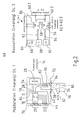
- Fig. 1 shows a first embodiment of an arrangement 10 for detection, transmission and processing safety-related signals.
- the arrangement 10 comprises a mobile station 12 such as a mobile handset, which safety signals S transmits over a radio link 14 to a base station 16.
- the mobile station 12 comprises a single-channel detection unit 18, such as a microprocessor with outputs 20 and inputs 22, each one of the outputs 20 with one of the Inputs 22 via an input means 24 such as a key switch, which as Opener is formed, can be connected together.
- the inputs 22 can also are referred to as safe inputs, which are a safety category such as SIL1 / KAT2 correspond.
- safe inputs which are a safety category such as SIL1 / KAT2 correspond.
- the output from the input means 24 signals they are start, stop and approval signals. From the at the detection means 18 adjacent safety-related signals signal data 26 are generated, the be transmitted via a transmitter 28 and the radio link 14 to the base station 16.
- the mobile station 12 comprises a power supply unit 30 such as an accumulator for powering the detection means 18 and the transmitter 28.
- the power supply for the detection means 18 and / or the transmitter 28 can by means of an input device 32 are interrupted as emergency stop switch.
- the mobile station connection terminals 34, 36, 38, 40th wherein the clamp 34 is connected to a first pole of the accumulator 30, whose second pole is grounded.
- Terminals 36 and 38 are internally connected 42, wherein the terminal 40 is internally connected to a power supply input the detection means 18 and / or the transmitter 28 is connected via a line 44.
- the input means 42 has two NC contacts 46, 48, which in each case connected to the contacts 36, 34 and 38, 40 are.
- the detection means 18 and / or the transmitter 28 is powered.
- the supply voltage is interrupted so that no signals are sent via the transmitter 28 can be.
- the base station 16 comprises a receiver 50, the output signals 52 thereof by means of processing units 54, 56 are processed.
- the processing units 54, 56 are as Microprocessors formed and coupled to each other via a connection 58, so that the signals can be evaluated two channels and compared with each other.
- the Base station 16 includes safe outputs 60.1, 60.2, each output having, respectively an output of the processing unit 54 and an output of the processing unit 56 is connected. Furthermore, non-secure outputs 62.1, 62.2, 62.3 are provided, for example are connected to the processing unit 56.
- a supply unit 64 is provided, which is connected to an input 66 is.
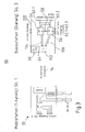
- Fig. 2 shows a second embodiment of an arrangement 68 for detection, transmission and processing safety-related signals.
- the arrangement 68 comprises a mobile station 70, which has substantially the same structure as the mobile station 12 of the arrangement 10.
- Via a NC contact 76, which is connected to the terminals 38 and 40 is the second pole 74 via the lead 44 with a first pole 78 of the detection means 18 connectable.
- the first pole 72 of the accumulator is connected via a normally closed contact 80 with the terminal 34 and a further supply line 82 with a second pole 84th the detection means 18 connectable.
- the mobile station 70 characterized by it that the power supply for the detection means 18 is bipolar separable.
- the order 68 has a base station 86 which faces the base station 16 therethrough differentiates that a first receiving unit 88 and a second receiving unit 90 is provided.
- each receiver 88, 90 via a connection 92, 94 with the first 54 and second evaluation unit 56 connected. That is, the received signals are each processed in the evaluation units 54, 56 and then via the connection 58 compared.
- safe inputs 96.1, 96.2 are provided which are connected to the evaluation units 54 and 56.
- the arrangement 98 comprises the mobile station 70, which corresponds to that according to FIG. 2. Furthermore, the arrangement comprises 98 a base station 100, which has a receiver 102, which via connections 104, 106 is connected to one of the evaluation units 54, 56. That is, in signals received by the receiver 102 are respectively transmitted to the receiving units 54, 56 and compared in these over the connection 58 with each other.
- the Mobile station 70 corresponds in structure to the mobile station of embodiments 68 and 98.
- the arrangement 108 includes a base station 110 corresponding to the base station 86 and also has two receivers 88, 90.
- each one of the receiver connect to one of the evaluation units 54, 56, additional connections 112, 114 are provided, which connect the receivers each with a further receiving unit, so that the receiver 88 with the receiving units 54 and 56 of the receiver 90th is connected to the receiving units 54, 56. Then takes place via the connection 58 a comparison of the received in the receiving units 54, 56 signals.
- Fig. 5 shows a fifth embodiment of an arrangement 116 for detection, transmission and processing safety-related signals.
- This arrangement includes a mobile station 118, with a first transmitter 120 and a second transmitter 122, which via Connections 124, 126 are connected to the detection unit 18.
- the base station 110 corresponds essentially to the base station according to FIG. 4, with two receivers 88, 90, which crosswise over the connections 92, 94, 112, 114 with the receiving units 54, 56 are connected.
- 68, 98, 108, now different radio links 14, 128, 130, 132 are executed, wherein Transmitter 120 to one of the receivers 98, 90, and the transmitter 122 to one of the receivers 88, 90 sends.
- the measures described will increase the availability of Radio link increased. This is a physically two-channel radio link.
- the arrangements 10, 68, 98, 108 are characterized in that the mobile station 12, 70 is constructed single-channel, whereby a simple and inexpensive construction can be realized which also allows a miniaturized design.
- the mobile station 12, 70 has about the possibility of the at the safe inputs 22.1 - 22.4 by input means 24 such as consent buttons, "+ buttons", "- buttons” or customized input devices generated To transmit signals via the radio link 14.
- input means 24 such as consent buttons, "+ buttons”, "- buttons” or customized input devices generated To transmit signals via the radio link 14.
- signals of low security level such as for example, KAT2 / SIL1.
- To transmit signals of this security level is a two-channel detection and two-channel transmission not necessarily provided.
- the invention provides that the Power supply 30 of the mobile station 12, 70 by means of the command device 32, which, for example As an emergency stop switch is designed to break one or two poles.
- the input 40 which can also be called the SIL3 input, becomes the supply voltage the detection means 18 and / or the transmitter 28 is turned off. This has As a result, signals can no longer be sent.
- the security level SIL3 corresponding base station 16 is a two-channel Monitoring of the radio link by means of time maintenance. In case of failure of signals, the safe outputs 60.1, 60.2 are switched to the safe state.
- a safety-related Control command of the input device 32 can in terms of the effect of the method insofar simply by interrupting the supply voltage of the components of the Mobile station 12 can be realized.
- the command device 32 as an emergency stop switch category SIL3 / KAT4 be formed, wherein the input means 24, for example, as a consent key in category SIL1 / KAT2.
- the command device 32 is a SIL3 / KAT4 class approval button and with the outputs 34, 36, 38, 40, the input means 24 then being e.g. as start button, stop button and / or tip buttons are formed.
- the base station 16, 86, 100, 110 has two semiconductor outputs 60.1, 60.2, the one Output of safety category KAT4 / SIL3, whose function depends on the inputs of the mobile station 12, 70, 118 can be parameterized. Not safe outputs 62.1 - 62.3 can also function as a function of Inputs 22.1 - 22.4 of the mobile station 12, 70, 118 are parameterized.
- the exits can function as "no radio link available" and / or "please test on the handset initiate "as well as customer-specific information.
- the inputs 96.1 and 96.2 can be used as safe inputs of the safety category KAT4 / SIL3 and can be used to activate the radio link 14 become.
- the mobile station 18 must therefore at least of safety category SIL1.
- SIL1 safety category
- the detection means 18, has at least four outputs 20.1 - 20.4 and at least four Inputs 22.1 - 22.4, each input 22.1 - 22.4 via a command device 24 with a the outputs 20.1 - 20.4 is connectable. Detects the detection means 18 at an entrance 22.1 - 22.4 the potential "HIGH" so can by switching off the assigned Output 20.1 - 20.4 a test be performed.
- Fig. 6 shows a possible transmission frame 14, which is preferably a triple Repetition of a telegram ST with safety-related information and subsequently the transmission of a telegram ZT with additional information provides.
- the structure of the message ST is shown in FIG.
- the message ST consists of an identifier part ID of the respective mobile station 12, 70, 118 with a length of 10 bits, a counter part CNT with a length of 2 bits, a data part DATA, which indicates the status of the SIL1 inputs 22.1 - 22.4, with a length of 4 bits and a checksum part CRC with a length of 16 bits.
- the telegram length comprises a total of 32 bits and reaches an inhibiting distance of 4.
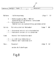
- the structure of the telegram ZT is shown in FIG.
- the telegram ZT includes a Battery part of one bit length, which reflects the state of the battery. Furthermore, an operating part is provided which comprises the length of one bit and the Operating state of the mobile unit represents. Furthermore, a caliber part is provided which also includes the length of one bit and indicates that the handset is calibrating performs. Furthermore, a reserve part with the length of 5 bits is provided.
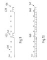
- Figs. 9 - 12 show possible structures of transmission cycles as time diagrams.
- Fig. 9 shows a first variant of a transmission cycle 136 with duty cycle of about 20%, that is, a Off time 138 of about 40 ms and a switch-on 140 of about 10 ms.
- In the turn-on period 140 are preferably transmitted 3 telegrams ST and in a frequency band of 433 MHz.
- Fig. 10 shows a transmission cycle 142 with 100% duty cycle in the 868 MHz frequency band. In each case 3 telegrams are transmitted without interruption within a period of 10 ms transmitted.
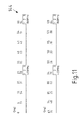
- a preferred variant of a transmission cycle 144 is shown in Fig. 11, wherein with alternating Frequencies for example 433 MHz and 868 MHz and a duty cycle of 10% in each case 3 telegrams are sent in intervals.
- FIG. 12 shows a variant of a transmission cycle 146 with 100% duty cycle in the 433 MHz and 868 MHz frequency band in the arrangement of two transmitters, as for example in the Arrangement 116 of the mobile station 118 and the transmitters 120, 122 is shown. There are also two receivers 88, 90 are provided, wherein the transmitters 120, 122 transmit simultaneously thus to build a two-channel radio link.
- each mobile station 12 sends a different frequency and each has its own identifier ID. Further the count CNT of each mobile station 12 is monitored by the base station 16. The transmission of the signals must also take place exactly after the transmission cycle shown in FIG. 3, otherwise the base station 16 switches to its safe state.
- a configuration software transmitted via a serial interface using a personal computer.
- the respective software is then used by the configuration software Identifier ID of the mobile station is set.
- the configuration software a table of CRC values is determined and transmitted to the mobile station 12. to Configuration of the base station 16, the identifier ID of the mobile stations 12 and the at the mobile stations occupied inputs 22.1 - 22.4 transmitted and the behavior of existing outputs 60.1 - 60.2; 62.1 - 62.3 configured.
- the radio link 14 is activated or disabled.
- the safe 60.1 - 60.2 or non-secure ones Outputs 62.1 - 62.3 of the base station 16 set.
- the base station checks at each Activation and / or after a certain time, whether all configured inputs 22.1 - 22.4 of safety category SIL1 were once opened and / or closed before the base station 16 releases one of the safe outputs 60.1-60.2.
- the signal "Protective door opened / closed" provided, runs a driven by the base station machine even without a radio link, if the protective door is closed, and only runs the radio link and release when the protective door is open.
- signals from electromechanical, electrical and / or electronic safety switching devices 24, 32 to the - also safety-related - Evaluation unit 54, 56 are transmitted via the radio link 14, wherein the Radio link 12 suitable by fault tolerant and / or erroneous measures is to meet the special requirements that are necessary to machines and mechanical systems to perform a so-called personal protection function, but on the other hand, she manages with a minimum of effort.
- the embodiment of the invention is characterized in particular by its structural Measures such as single-channel detection of safety-related low-security signals KAT2 / SIL1, through special monitoring routine such as time maintenance the base station as well as measures of data integrity such as assignment of an identifier ID to each mobile part, assignment of different frequencies to the mobile stations, monitoring the count of the respective mobile station by the base station and the Transmission in a given transmission cycle.
- structural Measures such as single-channel detection of safety-related low-security signals KAT2 / SIL1
- special monitoring routine such as time maintenance the base station as well as measures of data integrity such as assignment of an identifier ID to each mobile part, assignment of different frequencies to the mobile stations, monitoring the count of the respective mobile station by the base station and the Transmission in a given transmission cycle.
- the safety-related radio link can be provided with additional measures for fault sensitivity be provided.
- Any interference may cause a shutdown (Interruption) lead and thus to an unwanted machine stop Emergency stop comparable effect. From this point of view, it adds to the difficulty the scope of a safety-related radio link for machine applications As a rule, the factory floor is, so that - in contrast to so-called free-field applications - with additional reflections and also with variable disturbances is to be expected.
Landscapes
- Engineering & Computer Science (AREA)
- Computer Networks & Wireless Communication (AREA)
- Signal Processing (AREA)
- Mobile Radio Communication Systems (AREA)
Abstract
Description
- Identifier der Mobilstation
- Zählerstand, und
- Sendezyklus
- Fig. 1
- eine schematische Darstellung einer ersten Ausführungsform einer Anordnung zur Erfassung, Übertragung und Verarbeitung sicherheitsgerichteter Signale,
- Fig. 2
- eine schematische Darstellung einer zweiten Ausführungsform einer Anordnung zur Erfassung, Übertragung und Verarbeitung sicherheitsgerichteter Signale,
- Fig. 3
- eine schematische Darstellung einer dritten Ausführungsform einer Anordnung zur Erfassung, Übertragung und Verarbeitung sicherheitsgerichteter Signale,
- Fig. 4
- eine schematische Darstellung einer vierten Ausführungsform einer Anordnung zur Erfassung, Übertragung und Verarbeitung sicherheitsgerichteter Signale,
- Fig. 5
- eine schematische Darstellung einer fünften Ausführungsform einer Anordnung zur Erfassung, Übertragung und Verarbeitung sicherheitsgerichteter Signale,
- Fig. 6
- eine schematische Darstellung eines Übertragungsrahmens für zu übertragende Telegramme,
- Fig. 7
- einen schematischen Aufbau eines Telegramms mit sicherheitsgerichteten Informationen,
- Fig. 8
- einen schematischen Aufbau eines Telegramms mit zusätzlichen Informationen,
- Fig. 9
- ein schematisches Zeitdiagramm einer ersten Variante eines Sendezyklus,
- Fig. 10
- ein schematisches Zeitdiagramm einer zweiten Variante eines Sendezyklus,
- Fig. 11
- ein schematisches Zeitdiagramm einer dritten Variante eines Sendezyklus und
- Fig. 12
- ein schematisches Zeitdiagramm einer vierten Variante eines Sendezyklus.
| • sicherheitsrelevante Signale | V | 10 |
| • Zahl der Übertragungen bei m Teilnehmern | m-1 | 1 |
| • Bitfehlerwahrscheinlichkeit | p | 1,00E-02 |
| • R(p) bei HD = 12 | 1,85 E-16 | |
| • Λ | 6,75 E-10 |
- Maßnahme 1:
- Durch geeignete Schaltungstechniken unter Verwendung von Oberflächenwellenfilter sowie diskreten passiven oder auch aktiven Filterstufen wird die Breitbandigkeit der Funksignale wesentlich eingeschränkt.
- Maßnahme 2:
- Die Funkstrecke wird - um eine Fehlertoleranz zu gewährleisten - in einem geeigneten Mischbetrieb von zwei oder mehr Funkfrequenzen betrieben. Eine bevorzugte Ausführungsform besteht aus einem Dualband-System aufgebaut aus ISM- und SRD-Bereichen.
- Maßnahme 3:
- Auf der Empfängerseite werden zwei oder mehr Empfangsantennen realisiert.
- Maßnahme 4:
- Verwendung von numerisch kontrollierten Oszillatoren (numeric controled oscilators NCOs) bzw. Fractional N-Dividers (wie hier eingesetzt) zur hochauflösenden Einstellung sowohl des Local Oszillators im Empfänger als auch der Trägerfrequenz im Empfänger bilden die Grundlage eines schmalbandigen bzw. selektiven Funkbetriebes und der Immunität gegenüber breitbandigen Strahlern.
- Maßnahme 5:
- Verwendung der Modulationsarten FSK (Frequency Shift Keying) und deren Varianten (wie zum Beispiel GFSK - Gaussian Frequency Shift Keying) zur Immunisierung gegenüber Interferenzen, wie sie im Vergleich zu amplitudenmodulierten Varianten zu erwarten sind.
- Maßnahme 6:
- Verwendung von zwei- oder mehrstufigen Netzteilen zur Erhöhung der Empfängerempfindlichkeit als auch für einen zuverlässigen Sendebetrieb. Die Stufen der Netzteile können sowohl passiv (passive Filterstufen) als auch aktiv (zwei oder mehre Spannungsregler) oder in gemischten Variationen ausgeführt werden.
- Maßnahme 7:
- Verwendung des Manchester Datenformates zur Erhöhung der Empfängerempfindlichkeit und Stabilisierung der Tranceiver Arbeitspunkte.
- Maßnahme 8:
- Kalibration von Parametern der Funkstrecke zur Laufzeit unter der Verwendung von Umweltmessungen (zum Beispiel Temperaturmessung, Spannungsmessung, etc.).
- Maßnahme 9:
- Durch geeignete Schaltungstechniken (sogenannte Blocking-Maßnahmen) wird die Immunität gegenüber eingestrahlten Energien im Vergleich zur derzeit gesetzlich notwendigen erhöht.
- Maßnahme 10:
- Der Verfügbarkeitszeitraum wird vergrößert, indem es möglich gemacht wird, die Funkstrecke während des Aufladens eines Versorgungspannungs-Akkumulators weiterlaufen zu lassen.
Claims (30)
- Verfahren zur Erfassung, Übertragung und Auswertung sicherheitsgerichteter Signale mit mindestens einer zumindest einen Sender (28, 120, 122) aufweisenden Mobilstation (12, 70, 118) einer Funkstrecke (14) und einer zumindest einen Empfänger (50, 88, 90) aufweisenden Basisstation (16, 86, 100, 110),
dadurch gekennzeichnet, dass durch Unterbrechen der Stromversorgung der Mobilstation (12, 70, 118) die Aussendung von Signalen unterbrochen wird, wobei das Ausbleiben von Signalen durch die Basisstation (16) mittels einer Zeiterwartungshaltung überwacht wird, wobei die über die Funkstrecke (14) empfangenen Signale zweikanalig ausgewertet werden und bei Ausbleiben von Signalen innerhalb eines definierten Zeitfensters sicherheitsgerichtet Ausgänge (60.1 - 60.2) in einen sicheren Zustand geschaltet werden. - Verfahren nach Anspruch 1,
dadurch gekennzeichnet, dass die Stromversorgung einpolig unterbrochen wird. - Verfahren nach Anspruch 1 oder 2,
dadurch gekennzeichnet, dass die Stromversorgung zweipolig unterbrochen wird. - Verfahren nach zumindest einem der vorhergehenden Ansprüche,
dadurch gekennzeichnet, dass nur Signale geringer Sicherheitsstufe wie KAT2/SIL1 über die Funkstrecke (14) von der Mobilstation (12, 70, 118) zu der Basisstation (16, 86, 100, 110) übertragen werden. - Verfahren nach zumindest einem der vorhergehenden Ansprüche,
dadurch gekennzeichnet, dass zur Übertragung der sicherheitsgerichteten Signale geringer Sicherheitsstufe wie KAT2/SIL1 ein Telegramm (ST) mit sicherheitsgerichteten Informationen gebildet wird, welches einen Identifier-Teil (ID) der Mobilstation (12), einen Zähler-Teil (CNT), einen Daten-Teil (DATA) und einen Prüfsummen-Teil (CRC) aufweist. - Verfahren nach zumindest einem der vorhergehenden Ansprüche,
dadurch gekennzeichnet, dass das Telegramm (ST) innerhalb eines Übertragungsrahmens (134) mehrmals, vorzugsweise dreimal gesendet wird. - Verfahren nach zumindest einem der vorhergehenden Ansprüche,
dadurch gekennzeichnet, dass die Telegramme (ST) mit Duty-Cycle in Intervallen gesendet werden, vorzugsweise alle 40 ms, vorzugsweise drei Telegramme mit einer Gesamtdauer von ca. 10 ms. - Verfahren nach zumindest einem der vorhergehenden Ansprüche,
dadurch gekennzeichnet, dass innerhalb des Übertragungsrahmens (134) zusätzlich zu den Telegrammen (ST) ein Telegramm (ZT) mit zusätzlichen Informationen gemeldet wird. - Verfahren nach zumindest einem der vorhergehenden Ansprüche,
dadurch gekennzeichnet, dass das Telegramm (ZT) ein Batterie-Teil, ein Betriebs-Teil, ein Kalibrier-Teil und ein Reserve-Teil umfasst. - Verfahren nach zumindest einem der vorhergehenden Ansprüche,
dadurch gekennzeichnet, dass die Telegramme (ST, ZT) ohne Duty-Cycle kontinuierlich gesendet werden. - Verfahren nach zumindest einem der vorhergehenden Ansprüche,
dadurch gekennzeichnet, dass die Telegramme (ST, ZT) in verschiedenen Frequenzbändern wie 433 MHz-Band oder 868 MHz-Band gesendet werden. - Verfahren nach zumindest einem der vorhergehenden Ansprüche,
dadurch gekennzeichnet, dass die Telegramme (ST, ZT) im Duty-Cycle-Betrieb abwechselnd im 433 MHZ-Band und 868 MHZ-Band gesendet werden. - Verfahren nach zumindest einem der vorhergehenden Ansprüche,
dadurch gekennzeichnet, dass die Einschaltdauer (140) im Duty-Cycle-Betrieb ≤ 10 % der Periodendauer beträgt. - Verfahren nach zumindest einem der vorhergehenden Ansprüche,
dadurch gekennzeichnet, dass die Telegramme mit einer Baudrate von 19200 Baud gesendet werden. - Verfahren nach zumindest einem der vorhergehenden Ansprüche,
dadurch gekennzeichnet, dass die empfangenen Telegramme (68) in der Basisstation (16) zweikanalig ausgewertet werden auf:Identifier (ID) der Mobilstation (12)Zählerstand der Mobilstation (12) undSendezyklus - Verfahren nach zumindest einem der vorhergehenden Ansprüche,
dadurch gekennzeichnet, dass Prüfsummenwerte des CRC-Teils des Telegramms (68) in einer Tabelle der Mobilstation (12) gespeichert werden. - Verfahren nach zumindest einem der vorhergehenden Ansprüche,
dadurch gekennzeichnet, dass bei einer Inbetriebnahme eine Konfiguration der Mobilstation (12) und der Basisstation (16) mittels eines Personal Computers über eine serielle Schnittstelle erfolgt, wobei in der Mobilstation (12) der Identifier (ID) eingestellt wird und in die Tabelle die Prüfsummenwerte (CR10) übertragen werden und wobei in der Basisstation (16) der Identifier (ID) der Mobilstation (12) und die in der Mobilstation belegten Eingänge übermittelt werden und das Verhalten der Ausgänge der Basisstation (16) konfiguriert wird. - Verfahren nach zumindest einem der vorhergehenden Ansprüche,
dadurch gekennzeichnet, dass bei einem Verbindungsaufbau zwischen der Mobilstation (12) und der Basisstation die Funkstrecke (14) in Abhängigkeit von einem sicheren Eingang (22.1 - 22.4) der Mobilstation (12) und/oder der einem Eingang (66) der Basisstation (12) aktiviert und/oder deaktiviert wird und davon abhängig die sicheren und/oder die nicht sicheren Ausgänge der Mobilstation und/oder der Basisstation gesetzt werden. - Verfahren nach zumindest einem der vorhergehenden Ansprüche,
dadurch gekennzeichnet, dass die Basisstation bei jeder Aktivierung und/oder nach Ablauf einer bestimmten Zeit überprüft, ob alle konfigurierten sicheren Eingänge des Mobilteils (12) einmal geöffnet und/oder einmal geschlossen wurden, bevor die Basisstation (16) einen ihrer sicheren Ausgänge (60.1 - 60.2) freigibt. - Vorrichtung zur Erfassung, Übertragung, Auswertung sicherheitsgerichteter Signale, umfassend zumindest eine zumindest einen Sender (28) aufweisende Mobilstation (12, 70), eine Funkstrecke (14) sowie eine Basisstation (16, 86, 100, 110) mit einem Empfänger (50) und einer zweikanaligen Auswerteeinheit (54, 58),
dadurch gekennzeichnet, dass die Mobilstation (12) eine Energieversorgungseinheit (30) aufweist, wobei die Energieversorgung der Erfassungseinheit (18) und/oder des Senders (28) mittels eines elektromechanischen, elektrischen oder elektronischen Sicherheitsschaltgeräts (32) abschaltbar ist,
dass die Abschaltung der Mobilstation (12) durch die zweikanalige Basisstation (16) erfassbar ist und dass bei Ausbleiben der Signale der Mobilstation sichere Ausgänge (60.1 - 60.2) der Basisstation (16) in einen sicheren Zustand schaltbar sind. - Vorrichtung nach Anspruch 20,
dadurch gekennzeichnet, dass das Sicherheitsschaltgerät (32) mindestens einen zwangsöffnenden Öffnerkontakt (46, 48) aufweist, welcher in Reihenschaltung mit einer Versorgungsleitung (44) zur Energieversorgung der Erfassungseinheit (18) und/oder des Senders (28) liegt. - Vorrichtung nach zumindest einem der vorhergehenden Ansprüche,
dadurch gekennzeichnet, dass jeweils ein zwangsöffnender Kontakt (76, 80) in eine Versorgungsleitung (44, 82) zur Energieversorgung der Erfassungseinheit (18) und/oder des Senders (28) angeordnet ist. - Vorrichtung nach zumindest einem der vorhergehenden Ansprüche,
dadurch gekennzeichnet, dass die Basisstation (86) zwei Empfänger (88, 90) aufweist, wobei jedem Empfänger (88, 90) einer Empfangseinheit (54, 56) zugeordnet ist. - Vorrichtung nach zumindest einem der vorhergehenden Ansprüche,
dadurch gekennzeichnet, dass die Basisstation (100) einen Empfänger (102) aufweist, welcher mit der Empfangseinheit (54) und der Empfangseinheit (56) gekoppelt ist. - Vorrichtung nach zumindest einem der vorhergehenden Ansprüche,
dadurch gekennzeichnet, dass die Basisstation (110) zwei Empfänger (88, 90) aufweist, welche jeweils mit beiden Empfangseinheiten (54, 56) gekoppelt wird. - Vorrichtung nach zumindest einem der vorhergehenden Ansprüche,
dadurch gekennzeichnet, dass die Mobilstation (12, 70) ein Erfassungsmittel (18) wie Mikroprozessor aufweist, mit einer Vielzahl von Ausgängen (20.1 - 20.4) und einer Vielzahl von Eingängen (22.1 - 22.4), wobei jeweils ein Ausgang über ein Eingabemittel (24) wie Taster mit einem der Eingänge (22.1 - 22.4) verbindbar ist. - Vorrichtung nach zumindest einem der vorhergehenden Ansprüche,
dadurch gekennzeichnet, dass die Erfassungsmittel (54, 56) der Basisstation (16, 86, 100, 110) über eine Verbindung (28) miteinander gekoppelt sind, wodurch ein kreuzweiser Datenvergleich durchführbar ist. - Vorrichtung nach zumindest einem der vorhergehenden Ansprüche,
dadurch gekennzeichnet, dass zumindest eine der Erfassungseinheiten (54, 56) eine Vielzahl nicht sicherer Ausgänge (62.1 - 62.3) aufweist. - Vorrichtung nach zumindest einem der vorhergehenden Ansprüche,
dadurch gekennzeichnet, dass die sicheren Ausgänge (60.1 - 60.2) der Basisstation (16, 86, 100, 110) jeweils mit einem Ausgang der Erfassungseinheit 54 und einem Ausgang der Erfassungseinheit (56) verbunden sind. - Vorrichtung nach zumindest einem der vorhergehenden Ansprüche,
dadurch gekennzeichnet, dass die Basisstation (16, 86, 100, 110) über die sicheren Eingänge (96.1, 96.2) aktivierbar ist.
Applications Claiming Priority (4)
| Application Number | Priority Date | Filing Date | Title |
|---|---|---|---|
| DE10308180 | 2003-02-25 | ||
| DE10308180 | 2003-02-25 | ||
| DE10348703 | 2003-10-16 | ||
| DE10348703 | 2003-10-16 |
Publications (3)
| Publication Number | Publication Date |
|---|---|
| EP1453334A2 true EP1453334A2 (de) | 2004-09-01 |
| EP1453334A3 EP1453334A3 (de) | 2007-02-28 |
| EP1453334B1 EP1453334B1 (de) | 2008-12-03 |
Family
ID=32773166
Family Applications (1)
| Application Number | Title | Priority Date | Filing Date |
|---|---|---|---|
| EP04004113A Expired - Lifetime EP1453334B1 (de) | 2003-02-25 | 2004-02-24 | Verfahren und Vorrichtung zur Erfassung, Übertragung und Auswertung sicherheitsgerichteter Signale |
Country Status (2)
| Country | Link |
|---|---|
| EP (1) | EP1453334B1 (de) |
| DE (1) | DE502004008564D1 (de) |
Cited By (2)
| Publication number | Priority date | Publication date | Assignee | Title |
|---|---|---|---|---|
| EP1734683A2 (de) | 2005-06-14 | 2006-12-20 | Elan Schaltelemente GmbH & Co. KG | Verfahren zur Übertragung von Datentelegrammen über eine Funkstrecke |
| DE102007028709A1 (de) * | 2007-06-21 | 2008-12-24 | Pepperl + Fuchs Gmbh | Sicherheitsvorrichtung und Verfahren zur Übertragung von Sicherheitsdaten |
Family Cites Families (2)
| Publication number | Priority date | Publication date | Assignee | Title |
|---|---|---|---|---|
| DE4437490C2 (de) * | 1993-12-02 | 1996-07-25 | Gros Gerhard | Hochfrequenz-Empfangseinrichtung für besondere Sicherheitsanforderungen |
| DE19920299B4 (de) * | 1999-05-03 | 2008-01-03 | Siemens Ag | Verfahren sowie Vorrichtung zur Erfassung, Übertragung und Verarbeitung sicherheitsgerichteter Signale |
-
2004
- 2004-02-24 EP EP04004113A patent/EP1453334B1/de not_active Expired - Lifetime
- 2004-02-24 DE DE502004008564T patent/DE502004008564D1/de not_active Expired - Lifetime
Cited By (5)
| Publication number | Priority date | Publication date | Assignee | Title |
|---|---|---|---|---|
| EP1734683A2 (de) | 2005-06-14 | 2006-12-20 | Elan Schaltelemente GmbH & Co. KG | Verfahren zur Übertragung von Datentelegrammen über eine Funkstrecke |
| EP1734683A3 (de) * | 2005-06-14 | 2009-12-23 | Elan Schaltelemente GmbH & Co. KG | Verfahren zur Übertragung von Datentelegrammen über eine Funkstrecke |
| DE102007028709A1 (de) * | 2007-06-21 | 2008-12-24 | Pepperl + Fuchs Gmbh | Sicherheitsvorrichtung und Verfahren zur Übertragung von Sicherheitsdaten |
| JP2009043239A (ja) * | 2007-06-21 | 2009-02-26 | Pepperl & Fuchs Gmbh | 安全装置および保安データの送信方法 |
| DE102007028709B4 (de) * | 2007-06-21 | 2017-03-09 | Pepperl + Fuchs Gmbh | Datenübertragungsvorrichtung und Verfahren zur Übertragung von Daten |
Also Published As
| Publication number | Publication date |
|---|---|
| DE502004008564D1 (de) | 2009-01-15 |
| EP1453334B1 (de) | 2008-12-03 |
| EP1453334A3 (de) | 2007-02-28 |
Similar Documents
| Publication | Publication Date | Title |
|---|---|---|
| DE19920299B4 (de) | Verfahren sowie Vorrichtung zur Erfassung, Übertragung und Verarbeitung sicherheitsgerichteter Signale | |
| EP1221075B1 (de) | Vorrichtung zum steuern von sicherheitskritischen prozessen | |
| EP3069202B2 (de) | Sicherheitssteuerung mit konfigurierbaren eingängen | |
| EP1738382A1 (de) | Sicherheitsschalteinrichtung für eine sicherheitsschaltung | |
| EP1738383B2 (de) | Meldegerät für eine sicherheitsschaltung | |
| EP2007022B1 (de) | Funkverfahren für Tore | |
| EP2691969B1 (de) | Sicherheitsschaltungsanordnung zum fehlersicheren ein- oder ausschalten einer gefährlichen anlage | |
| EP3014365B1 (de) | Sicherheitsschaltvorrichtung zur detektion von fehlerhaften eingängen | |
| EP0742500A2 (de) | Sichere Tipptasten- und Schalterfunktionen mit Fehleraufdeckung | |
| EP3170287A1 (de) | Steuer- und datenübertragungssystem, gateway-modul, e/a-modul und verfahren zur prozesssteuerung | |
| EP1059576A2 (de) | Sicherheitsschalteranordnung mit zwei Aktoren | |
| EP2887163B1 (de) | Überwachungsvorrichtung, Sicherheitssystem und Verfahren zum Betreiben eines Sicherheitssystems | |
| EP2685660B1 (de) | Verfahren und System zur Erfassung, Übertragung und Auswertung sicherheitsgerichteter Signale | |
| EP1453334B1 (de) | Verfahren und Vorrichtung zur Erfassung, Übertragung und Auswertung sicherheitsgerichteter Signale | |
| DE102011051629B3 (de) | Sicherheitsbussystem | |
| DE19517037A1 (de) | Funk-Alarmanlage | |
| EP2215615B1 (de) | Vorrichtung und verfahren zur drahtlosen vernetzung von geräten der automatisierungstechnik | |
| EP2667304A2 (de) | Eingang-Ausgangsmodul | |
| DE19940874B4 (de) | Verfahren zum Konfigurieren eines sicheren Busteilnehmers und sicheres Steuerungssystem mit einem solchen | |
| DE10359898A1 (de) | Verfahren zum Steuern und Überwachen von Maschinen | |
| DE102004040059A1 (de) | Verfahren und Vorrichtung zur sicherheitsgerichteten drahtlosen Signalübertragung | |
| EP4276498B1 (de) | Überwachungseinrichtung | |
| DE102004046476B4 (de) | Verfahren zur Erhöhung der Verfügbarkeit einer Funkstrecke | |
| EP2651079B1 (de) | Elektrische installationsanordnung | |
| EP0222682B1 (de) | Signalübertragungsanordnung für eine Vergleichsschutzeinrichtung |
Legal Events
| Date | Code | Title | Description |
|---|---|---|---|
| PUAI | Public reference made under article 153(3) epc to a published international application that has entered the european phase |
Free format text: ORIGINAL CODE: 0009012 |
|
| AK | Designated contracting states |
Kind code of ref document: A2 Designated state(s): AT BE BG CH CY CZ DE DK EE ES FI FR GB GR HU IE IT LI LU MC NL PT RO SE SI SK TR |
|
| AX | Request for extension of the european patent |
Extension state: AL LT LV MK |
|
| PUAL | Search report despatched |
Free format text: ORIGINAL CODE: 0009013 |
|
| AK | Designated contracting states |
Kind code of ref document: A3 Designated state(s): AT BE BG CH CY CZ DE DK EE ES FI FR GB GR HU IE IT LI LU MC NL PT RO SE SI SK TR |
|
| AX | Request for extension of the european patent |
Extension state: AL LT LV MK |
|
| RIC1 | Information provided on ipc code assigned before grant |
Ipc: H04Q 7/32 20060101AFI20040609BHEP Ipc: G08C 17/02 20060101ALI20070119BHEP |
|
| 17P | Request for examination filed |
Effective date: 20070803 |
|
| 17Q | First examination report despatched |
Effective date: 20070912 |
|
| AKX | Designation fees paid |
Designated state(s): CH DE FR IT LI SE |
|
| GRAP | Despatch of communication of intention to grant a patent |
Free format text: ORIGINAL CODE: EPIDOSNIGR1 |
|
| GRAS | Grant fee paid |
Free format text: ORIGINAL CODE: EPIDOSNIGR3 |
|
| GRAA | (expected) grant |
Free format text: ORIGINAL CODE: 0009210 |
|
| AK | Designated contracting states |
Kind code of ref document: B1 Designated state(s): CH DE FR IT LI SE |
|
| REG | Reference to a national code |
Ref country code: CH Ref legal event code: EP |
|
| REF | Corresponds to: |
Ref document number: 502004008564 Country of ref document: DE Date of ref document: 20090115 Kind code of ref document: P |
|
| REG | Reference to a national code |
Ref country code: CH Ref legal event code: NV Representative=s name: LUCHS & PARTNER PATENTANWAELTE |
|
| REG | Reference to a national code |
Ref country code: SE Ref legal event code: TRGR |
|
| PLBE | No opposition filed within time limit |
Free format text: ORIGINAL CODE: 0009261 |
|
| STAA | Information on the status of an ep patent application or granted ep patent |
Free format text: STATUS: NO OPPOSITION FILED WITHIN TIME LIMIT |
|
| 26N | No opposition filed |
Effective date: 20090904 |
|
| REG | Reference to a national code |
Ref country code: FR Ref legal event code: PLFP Year of fee payment: 13 |
|
| REG | Reference to a national code |
Ref country code: FR Ref legal event code: PLFP Year of fee payment: 14 |
|
| REG | Reference to a national code |
Ref country code: FR Ref legal event code: PLFP Year of fee payment: 15 |
|
| PGFP | Annual fee paid to national office [announced via postgrant information from national office to epo] |
Ref country code: DE Payment date: 20180226 Year of fee payment: 15 Ref country code: CH Payment date: 20180216 Year of fee payment: 15 |
|
| PGFP | Annual fee paid to national office [announced via postgrant information from national office to epo] |
Ref country code: IT Payment date: 20180227 Year of fee payment: 15 Ref country code: FR Payment date: 20180223 Year of fee payment: 15 Ref country code: SE Payment date: 20180227 Year of fee payment: 15 |
|
| REG | Reference to a national code |
Ref country code: DE Ref legal event code: R119 Ref document number: 502004008564 Country of ref document: DE |
|
| REG | Reference to a national code |
Ref country code: CH Ref legal event code: PL |
|
| REG | Reference to a national code |
Ref country code: SE Ref legal event code: EUG |
|
| PG25 | Lapsed in a contracting state [announced via postgrant information from national office to epo] |
Ref country code: SE Free format text: LAPSE BECAUSE OF NON-PAYMENT OF DUE FEES Effective date: 20190225 |
|
| PG25 | Lapsed in a contracting state [announced via postgrant information from national office to epo] |
Ref country code: CH Free format text: LAPSE BECAUSE OF NON-PAYMENT OF DUE FEES Effective date: 20190228 Ref country code: LI Free format text: LAPSE BECAUSE OF NON-PAYMENT OF DUE FEES Effective date: 20190228 |
|
| PG25 | Lapsed in a contracting state [announced via postgrant information from national office to epo] |
Ref country code: DE Free format text: LAPSE BECAUSE OF NON-PAYMENT OF DUE FEES Effective date: 20190903 |
|
| PG25 | Lapsed in a contracting state [announced via postgrant information from national office to epo] |
Ref country code: IT Free format text: LAPSE BECAUSE OF NON-PAYMENT OF DUE FEES Effective date: 20190224 Ref country code: FR Free format text: LAPSE BECAUSE OF NON-PAYMENT OF DUE FEES Effective date: 20190228 |