EP1453183A2 - Brush holder arrangement of dc motor - Google Patents
Brush holder arrangement of dc motor Download PDFInfo
- Publication number
- EP1453183A2 EP1453183A2 EP04009986A EP04009986A EP1453183A2 EP 1453183 A2 EP1453183 A2 EP 1453183A2 EP 04009986 A EP04009986 A EP 04009986A EP 04009986 A EP04009986 A EP 04009986A EP 1453183 A2 EP1453183 A2 EP 1453183A2
- Authority
- EP
- European Patent Office
- Prior art keywords
- brushes
- brush holder
- motor
- brush
- commutator
- Prior art date
- Legal status (The legal status is an assumption and is not a legal conclusion. Google has not performed a legal analysis and makes no representation as to the accuracy of the status listed.)
- Granted
Links
Images


Classifications
-
- H—ELECTRICITY
- H01—ELECTRIC ELEMENTS
- H01R—ELECTRICALLY-CONDUCTIVE CONNECTIONS; STRUCTURAL ASSOCIATIONS OF A PLURALITY OF MUTUALLY-INSULATED ELECTRICAL CONNECTING ELEMENTS; COUPLING DEVICES; CURRENT COLLECTORS
- H01R39/00—Rotary current collectors, distributors or interrupters
- H01R39/02—Details for dynamo electric machines
- H01R39/38—Brush holders
- H01R39/385—Means for mechanical fixation of the brush holder
-
- H—ELECTRICITY
- H01—ELECTRIC ELEMENTS
- H01R—ELECTRICALLY-CONDUCTIVE CONNECTIONS; STRUCTURAL ASSOCIATIONS OF A PLURALITY OF MUTUALLY-INSULATED ELECTRICAL CONNECTING ELEMENTS; COUPLING DEVICES; CURRENT COLLECTORS
- H01R39/00—Rotary current collectors, distributors or interrupters
- H01R39/02—Details for dynamo electric machines
- H01R39/38—Brush holders
- H01R39/381—Brush holders characterised by the application of pressure to brush
-
- H—ELECTRICITY
- H01—ELECTRIC ELEMENTS
- H01R—ELECTRICALLY-CONDUCTIVE CONNECTIONS; STRUCTURAL ASSOCIATIONS OF A PLURALITY OF MUTUALLY-INSULATED ELECTRICAL CONNECTING ELEMENTS; COUPLING DEVICES; CURRENT COLLECTORS
- H01R39/00—Rotary current collectors, distributors or interrupters
- H01R39/02—Details for dynamo electric machines
- H01R39/38—Brush holders
- H01R39/41—Brush holders cartridge type
- H01R39/415—Brush holders cartridge type with self-recoiling spring
-
- H—ELECTRICITY
- H02—GENERATION; CONVERSION OR DISTRIBUTION OF ELECTRIC POWER
- H02K—DYNAMO-ELECTRIC MACHINES
- H02K5/00—Casings; Enclosures; Supports
- H02K5/04—Casings or enclosures characterised by the shape, form or construction thereof
- H02K5/14—Means for supporting or protecting brushes or brush holders
- H02K5/143—Means for supporting or protecting brushes or brush holders for cooperation with commutators
- H02K5/148—Slidably supported brushes
-
- H—ELECTRICITY
- H01—ELECTRIC ELEMENTS
- H01R—ELECTRICALLY-CONDUCTIVE CONNECTIONS; STRUCTURAL ASSOCIATIONS OF A PLURALITY OF MUTUALLY-INSULATED ELECTRICAL CONNECTING ELEMENTS; COUPLING DEVICES; CURRENT COLLECTORS
- H01R2201/00—Connectors or connections adapted for particular applications
- H01R2201/26—Connectors or connections adapted for particular applications for vehicles
-
- H—ELECTRICITY
- H01—ELECTRIC ELEMENTS
- H01R—ELECTRICALLY-CONDUCTIVE CONNECTIONS; STRUCTURAL ASSOCIATIONS OF A PLURALITY OF MUTUALLY-INSULATED ELECTRICAL CONNECTING ELEMENTS; COUPLING DEVICES; CURRENT COLLECTORS
- H01R39/00—Rotary current collectors, distributors or interrupters
- H01R39/02—Details for dynamo electric machines
- H01R39/04—Commutators
- H01R39/06—Commutators other than with external cylindrical contact surface, e.g. flat commutators
-
- Y—GENERAL TAGGING OF NEW TECHNOLOGICAL DEVELOPMENTS; GENERAL TAGGING OF CROSS-SECTIONAL TECHNOLOGIES SPANNING OVER SEVERAL SECTIONS OF THE IPC; TECHNICAL SUBJECTS COVERED BY FORMER USPC CROSS-REFERENCE ART COLLECTIONS [XRACs] AND DIGESTS
- Y10—TECHNICAL SUBJECTS COVERED BY FORMER USPC
- Y10T—TECHNICAL SUBJECTS COVERED BY FORMER US CLASSIFICATION
- Y10T74/00—Machine element or mechanism
- Y10T74/13—Machine starters
Definitions
- the present invention relates to a DC motor which is suitable for a vehicle starter.
- a starter is disclosed in JP-U-63-143040.
- the motor of this starter has a face-contact commutator.
- the face-contact commutator has a surface perpendicular to an armature shaft to be in contact with a pair of brushes.
- This face-contact commutator and a common cylindrical commutator in that: it is necessary for the cylindrical commutator to have an axial marginal length for receiving the brushes, while it is not necessary for the face-contact commutator to have the same.
- the face-contact commutator is effective to shorten the axial length of the motor.
- the motor disclosed in the publication has compression coil springs for biasing the brushes against a commutator.
- Compression coil springs are disposed at the rear end of brushes opposite to the commutator. If the spring constant of the coil spring is lowered and the initial spring, is increased to provide a sufficient spring force for a long time until the brushes are worn away, the total length of springs is increased. That is, although the face-contact commutator shortens the length of the armature, the total length of the motor can not be reduced.
- the springs may be fatigued shortly due to heat of the motor.
- a resinous holder holding a brush holder thereon is fastened to a bracket by a bolt, and the bracket together with a torque sensor unit disposed thereon is also fastened to a flange of motor casing by bolts.
- Through holes are formed in the bracket and the flange and female screw holes are formed in the torque sensor unit. Because the inside diameter of the through holes is larger than the outside diameter of the bolts, clearances are formed between the bolts and the bracket's through holes. As a result, the bracket may move in the clearances, and this makes the circumferential positioning difficult.
- the bracket may move within the clearance due to vibration. This changes circumferential position of the brush holder relative to the yoke.
- the present invention has been made in view of the above circumstances and has a main.object to reduce the total length of a DC motor.
- each brush spring has a springy spring body and a spring arm extending from the brush body to bias the rear end of one of the brushes, and the spring body is disposed at a side of the one of the brushes within the axial length of the one of the brushes. Accordingly, the total length of the DC motor can be reduced.
- Another object of the invention is to provide a DC motor which is easy to position the yoke and brush holder accurately.
- the brush holder unit is comprised of a metal brush holder and a resinous holder having a plurality of cavities for respectively accommodating the blush holders.
- Each of the brush holders has a stopper means for preventing the same from falling away from one of the cavities.
- the brush holders can be fixed to the resinous holder easily without screws or rivets. Because the brush holder is surrounded by resinous material and a distance between the brush holder and an end frame can be provided, sufficient insulation can be provided even if abrasion powders of the brushes, due to long use, stick to the brush holder. Because the brushes are accommodated by the meatal brush holder, the resinous holder is protected from thermal damage even if the brushes are over-heated.
- the stopper means may have a support arm which has an edge in engagement with a groove formed in the resinous holder. If the support arm is applied reaction force of the brush spring, the support arm and the brush holder are prevented by the edge of the support arm from deforming.
- the commutator of the DC motor may be a face-contact commutator whose surface is perpendicular to a shaft of the armature.
- a rubber bushing is fixed to the brush holder unit so that the yoke and the brush holder unit are positioned with the rubber bushing interposed therebetween. This, prevents slippage of the brush holder unit in the circumferential direction.
- a starter motor having a brush holder unit according to a first embodiment is described with reference to Figs. 1 - 7.
- Starter 1 is comprised of DC motor 2, reduction unit 3 for reducing rotation speed of motor 2, output shaft 4 for transmitting the torque of motor 2, pinion gear 6 which is engaged with a ring gear of an engine when engine is started, one way clutch 7 which transmits the rotation of output shaft 4 to pinion gear 6, and magnet switch 8 which turns on or off motor's contacts (not shown) of a motor driving circuit (not shown).
- Reduction unit 3 is comprised of a sun gear 31 having external teeth around armature shaft 12, ring-shape internal gear 32 having internal teeth surrounding sun gear 31, planetary gear 33 interposed between sun gear 31 and internal gear 32 in mesh with sun and internal gears 31, 32.
- Planetary gear 33 rotates on its own axis and revolves around sun gear 31, so that the rotation of planetary gear 33 can be transmitted to output shaft 4 via pin 19.
- Output shaft 4 is disposed in front of armature 14 to align with armature shaft 12.
- the front end of output shaft 4 is supported by a front housing via a bearing, and the rear end thereof is supported by bearing support via bearing 17.
- Internal gear 32 is fitted to the inner periphery of yoke 9 to be rotation-controlled.
- Pinion gear 6 is slidably fitted to the outer periphery of output shaft 4 via bearing 5 so as to move forward on output shaft 4 to engage the ring gear, thereby transmitting the rotation of output shaft 4 to the ring gear.
- One way clutch 7 is fitted to a helical spline, which is formed on the outer periphery of output shaft 4, to be movable together with pinion gear 6.
- One way clutch 7 transmits the rotation of output shaft 4 to pinion gear and cut the connection between output shaft 4 and pinion gear 6 if an engine rotates pinion gear 6 at a speed higher than the rotation speed of output shaft 4.
- Magnet switch 8 opens or closes internal contacts as a built-in plunger (not shown) moves and moves pinion gear 6 via a lever back and forth together with one-way clutch 7 on output shaft 4.
- Motor 2 is comprised of cylindrical yoke 9 made of soft iron, end frame 10 for closing the rear opening of yoke 9, stator poles 11 (e.g. permanent magnets) disposed on the cylindrical inner periphery of yoke 9, armature 14 which has face-contact commutator 13 whose surface is perpendicular to armature shaft 12, and a brush holder unit 15 which holds two pairs of positive brush 151 and negative brush 152 and their brush springs 16.
- the pairs of brushes 151, 152 slidably in contact with commutator 13, and brush springs 16 respectively press the pair of brushes 151, 152 against commutator 13.
- armature 14 In armature 14, one end of armature shaft 12 is supported by bearing 17 at the inner periphery of cylindrical cavity formed at the rear end of output shaft 4 and the other end is supported by bearing 18 at the inner periphery of a cylindrical portion formed at the central portion of end frame 10. Washer 19 and stopper ring 20 are fitted to a portion of the other end of armature shaft 12 rearward from bearing 18, so that armature 14 is restricted to move in the axial direction.
- Brush holder unit 15 is comprised of four cylindrical metal brush holders 21 and resinous holder 22 for supporting brush holders 21.
- Resinous holder 22 has four cavities 22a having inner wall 22b and four grooves 22c, and brush holders 21 are respectively inserted into four cavities 22a.
- Each of brush holders 21 is made of a metal plate, which is shaped into a rectangular pipe. Each is inserted into one of cavities 22a. Each of brush holders 21 has claw 21a extending from one side thereof and support arm 26 integrated therewith. Claw 21a engages inner wall 22b to prevent brush holder 21 from falling away from cavity 22a, as shown in Fig. 5. An edge of support arm 26 engages one of grooves 22c as shown in Fig. 6.
- Resinous holder 22 is fastened to end frame 10 by a pair of metal member 23 and 24 and bolts. Metal members 23 and 24 are respectively disposed at opposite portions around the center of hole 15a. As shown in Fig. 2, resinous holder 22 also has U-shaped opening 22d at an upper edge thereof to have rubber bushing 29 press-fitted therein. U-shaped opening 22d has semicircular hollows formed at opposite peripheral sides at a certain interval.
- Rubber bushing 29 has semicircular press-fit portions 30a to be press-fitted to the hollows of U-shaped opening 22d and engagement groove 30b to be engaged with U-shaped opening 22d.
- Brush holder unit 15 also has a pair of positive brushes 151 and a pair of negative brushes 152, which are slidably held inside the cylindrical portion of brush holders 21.
- brush holder 22 can be fixed to resinous holder 22 easily without screw or rivet.
- Brush holder 22 is surrounded by resinous holder 21, and the distance between brush holder 21 and end frame, which is grounded, can be made long enough to insulate brush holder 21. Even if brush abrasion powders stick to brush holder 21, the same can be insulated for a long time. If brushes 15 are overheated, resinous holder 22 can be protected by brush holder 21 from heat damage.
- Each of positive brushes 151 has a pigtail 15a which is welded to conductive metal member 27.
- Lead wire 28 is connected to metal member 27 and a motor contact (stationary contact) of magnetic switch 8.
- Lead wire 28 is held by rubber bushing 29 fitted in a side opening of yoke 9 and insulated by the same from yoke 9.
- Each of negative brushes 152 has pig tail 15b which is connected to metal member 23 which is grounded.
- Metal member 23 functions as an earth terminal for negative brushes 152.
- each of brush springs 16 is comprised of spirally wound spring body 161 made of a long thin metal strip and springy arm extending from the outermost portion of spring body 161.
- the edge of springy arm 162 biases rear surface 15c of brush 15 against commutator 13.
- Spring body 161 is disposed on one side of brush 15 so that brush springs 16 can be supported by support arms 26 as described above.
- Spring body 161 is disposed so that the outside diameter d thereof can be disposed within the axial length l of brushes 151, 152.
- each spring body 161 is disposed within the axial length l of brushes 151, 152, the total length of motor 2 is shortened significantly.
- Brush springs 16 are not required to position at the rear of brushes 151, 152, and brush body 161 can be disposed at one side of each of brushes 151, 152.
- a coil spring made of a piano wire can be used as spring body 161.
- press-fit portions 30a of rubber bushing 29 are press-fitted to the hollows of opening 22d.
- groove 29b of rubber bushing 29 is press-fitted into opening 22d through the side opening of yoke 9.
- end frame 10 is placed at the back of brush holder unit 15, and, as shown in Fig. 4, bolt 25 is screwed into female screw of metal member 23 through a hole of end frame 10, thereby fixing brush holder unit 15 to end frame 10.
- support arm 26 is formed separately from brush holder 21.
- Support arm 26 is made of a simple plate or rod having a suitable length and opposite ends thereof are engaged with grooves 22c of resinous holder 22, as in the first embodiment.
- brush holders 21 can be manufactured more easily than the first embodiment.
- Armature 14 as shown in Figs. 8 and 9, is provided with a cylindrical commutator having a plurality of commutator segments 13a around armature shaft 12 and brushes 151, 152.
- Resinous holder 22 is fastened to end frame 10 by screws or the like and has cavities 22a for accommodating brush holder 21. Cavities 22a penetrate resinous holder 22 in the radial direction of commutator 13. Therefore, brush holder 21 can be inserted into cavity 22a either from the side of commutator 13 or the side of end frame 10. Each of brush holders 21 is held by support arm 26 in the same manner as in the first embodiment.
- Each of brush springs 16 is a spirally wound type as in the first embodiment and disposed at a side of brush holders as shown in Fig. 8, and supported by one of support arms 26. Brushes 151, 152 are respectively inserted in the cylindrical inside of brush holders 21 and biased by brush springs 16 against commutator 13.
Landscapes
- Engineering & Computer Science (AREA)
- Power Engineering (AREA)
- Motor Or Generator Current Collectors (AREA)
- Motor Or Generator Frames (AREA)
- Connection Of Motors, Electrical Generators, Mechanical Devices, And The Like (AREA)
- Dc Machiner (AREA)
Abstract
Description
- The present invention relates to a DC motor which is suitable for a vehicle starter.
- As a prior art, a starter is disclosed in JP-U-63-143040. The motor of this starter has a face-contact commutator. The face-contact commutator has a surface perpendicular to an armature shaft to be in contact with a pair of brushes. There is a difference between this face-contact commutator and a common cylindrical commutator in that: it is necessary for the cylindrical commutator to have an axial marginal length for receiving the brushes, while it is not necessary for the face-contact commutator to have the same. In other words, the face-contact commutator is effective to shorten the axial length of the motor.
- The motor disclosed in the publication has compression coil springs for biasing the brushes against a commutator. Compression coil springs are disposed at the rear end of brushes opposite to the commutator. If the spring constant of the coil spring is lowered and the initial spring, is increased to provide a sufficient spring force for a long time until the brushes are worn away, the total length of springs is increased. That is, although the face-contact commutator shortens the length of the armature, the total length of the motor can not be reduced.
- If the spring force is increased to shorten its length, the springs may be fatigued shortly due to heat of the motor.
- As disclosed in JP-A-7-194066, a resinous holder holding a brush holder thereon is fastened to a bracket by a bolt, and the bracket together with a torque sensor unit disposed thereon is also fastened to a flange of motor casing by bolts. Through holes are formed in the bracket and the flange and female screw holes are formed in the torque sensor unit. Because the inside diameter of the through holes is larger than the outside diameter of the bolts, clearances are formed between the bolts and the bracket's through holes. As a result, the bracket may move in the clearances, and this makes the circumferential positioning difficult.
- Even after the motor casing and the brush holder are assembpled, the bracket may move within the clearance due to vibration. This changes circumferential position of the brush holder relative to the yoke.
- In addition, the torque sensor and the motor casing with the bracket interposed therebetween necessitate to align three through holes thereof with each other.
- The present invention has been made in view of the above circumstances and has a main.object to reduce the total length of a DC motor.
- According to a main feature of the invention, each brush spring has a springy spring body and a spring arm extending from the brush body to bias the rear end of one of the brushes, and the spring body is disposed at a side of the one of the brushes within the axial length of the one of the brushes. Accordingly, the total length of the DC motor can be reduced.
- Another object of the invention is to provide a DC motor which is easy to position the yoke and brush holder accurately.
- The brush holder unit is comprised of a metal brush holder and a resinous holder having a plurality of cavities for respectively accommodating the blush holders. Each of the brush holders has a stopper means for preventing the same from falling away from one of the cavities.
- Therefore, the brush holders can be fixed to the resinous holder easily without screws or rivets. Because the brush holder is surrounded by resinous material and a distance between the brush holder and an end frame can be provided, sufficient insulation can be provided even if abrasion powders of the brushes, due to long use, stick to the brush holder. Because the brushes are accommodated by the meatal brush holder, the resinous holder is protected from thermal damage even if the brushes are over-heated.
- The stopper means may have a support arm which has an edge in engagement with a groove formed in the resinous holder. If the support arm is applied reaction force of the brush spring, the support arm and the brush holder are prevented by the edge of the support arm from deforming.
- The commutator of the DC motor may be a face-contact commutator whose surface is perpendicular to a shaft of the armature.
- According to another feature of the invention, a rubber bushing is fixed to the brush holder unit so that the yoke and the brush holder unit are positioned with the rubber bushing interposed therebetween. This, prevents slippage of the brush holder unit in the circumferential direction.
- Other objects, features and characteristics of the present invention as well as the functions of related parts of the present invention will become clear from a study of the following detailed description, the appended claims,and the drawings. In the drawings:
- Fig. 1 is a cross-sectional side view of a starter motor according to a first embodiment of the invention.
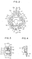
- Fig. 2 is a front view of a brush holder unit viewed from the side of an armature of the starter motor.
- Fig. 3 is a cross-sectional view of the portion shown in Fig. 2 cut along line A-A.
- Fig. 4 is a cross-sectional view of the portion shown in Fig. 2 cut along line B-B.
- Fig. 5 is a cross-sectional view of the portion shown in Fig. 2 cut along line C-C.
- Fig. 6 is a cross-sectional view of the portion shown in Fig- 2 cut along line D-D.
- Fig. 7 is a front view of a brush holder unit according to a second embodiment of the invention.
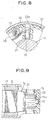
- Fig. 8 is a fragmentary cross-sectional view of a brush holder unit according to a third embodiment of the invention.
- Fig. 9 is a fragmentary cross-sectional side view of the armature having the brush holder unit according to the third embodiment.
-
- A DC motor according to the invention is described with reference to the appended drawings.
- A starter motor having a brush holder unit according to a first embodiment is described with reference to Figs. 1 - 7.
- Starter 1 is comprised of DC motor 2, reduction unit 3 for reducing rotation speed of motor 2,
output shaft 4 for transmitting the torque of motor 2,pinion gear 6 which is engaged with a ring gear of an engine when engine is started, one way clutch 7 which transmits the rotation ofoutput shaft 4 topinion gear 6, and magnet switch 8 which turns on or off motor's contacts (not shown) of a motor driving circuit (not shown). - Reduction unit 3 is comprised of a
sun gear 31 having external teeth aroundarmature shaft 12, ring-shapeinternal gear 32 having internal teeth surroundingsun gear 31, planetary gear 33 interposed betweensun gear 31 andinternal gear 32 in mesh with sun andinternal gears sun gear 31, so that the rotation of planetary gear 33 can be transmitted tooutput shaft 4 viapin 19. -
Output shaft 4 is disposed in front ofarmature 14 to align witharmature shaft 12. The front end ofoutput shaft 4 is supported by a front housing via a bearing, and the rear end thereof is supported by bearing support via bearing 17.Internal gear 32 is fitted to the inner periphery ofyoke 9 to be rotation-controlled. -
Pinion gear 6 is slidably fitted to the outer periphery ofoutput shaft 4 via bearing 5 so as to move forward onoutput shaft 4 to engage the ring gear, thereby transmitting the rotation ofoutput shaft 4 to the ring gear. - One way clutch 7 is fitted to a helical spline, which is formed on the outer periphery of
output shaft 4, to be movable together withpinion gear 6. One way clutch 7 transmits the rotation ofoutput shaft 4 to pinion gear and cut the connection betweenoutput shaft 4 andpinion gear 6 if an engine rotatespinion gear 6 at a speed higher than the rotation speed ofoutput shaft 4. - Magnet switch 8 opens or closes internal contacts as a built-in plunger (not shown) moves and moves
pinion gear 6 via a lever back and forth together with one-way clutch 7 onoutput shaft 4. - Motor 2 is comprised of
cylindrical yoke 9 made of soft iron,end frame 10 for closing the rear opening ofyoke 9, stator poles 11 (e.g. permanent magnets) disposed on the cylindrical inner periphery ofyoke 9,armature 14 which has face-contact commutator 13 whose surface is perpendicular toarmature shaft 12, and abrush holder unit 15 which holds two pairs ofpositive brush 151 andnegative brush 152 and theirbrush springs 16. The pairs ofbrushes commutator 13, andbrush springs 16 respectively press the pair ofbrushes commutator 13. - In
armature 14, one end ofarmature shaft 12 is supported bybearing 17 at the inner periphery of cylindrical cavity formed at the rear end ofoutput shaft 4 and the other end is supported bybearing 18 at the inner periphery of a cylindrical portion formed at the central portion ofend frame 10.Washer 19 andstopper ring 20 are fitted to a portion of the other end ofarmature shaft 12 rearward frombearing 18, so thatarmature 14 is restricted to move in the axial direction. -
Brush holder unit 15 is comprised of four cylindricalmetal brush holders 21 andresinous holder 22 for supportingbrush holders 21.Resinous holder 22 has fourcavities 22a havinginner wall 22b and fourgrooves 22c, andbrush holders 21 are respectively inserted into fourcavities 22a. - Each of
brush holders 21 is made of a metal plate, which is shaped into a rectangular pipe. Each is inserted into one ofcavities 22a. Each ofbrush holders 21 hasclaw 21a extending from one side thereof and supportarm 26 integrated therewith.Claw 21a engagesinner wall 22b to preventbrush holder 21 from falling away fromcavity 22a, as shown in Fig. 5. An edge ofsupport arm 26 engages one ofgrooves 22c as shown in Fig. 6. -
Resinous holder 22 is fastened to endframe 10 by a pair ofmetal member Metal members hole 15a. As shown in Fig. 2,resinous holder 22 also hasU-shaped opening 22d at an upper edge thereof to haverubber bushing 29 press-fitted therein.U-shaped opening 22d has semicircular hollows formed at opposite peripheral sides at a certain interval. -
Rubber bushing 29 has semicircular press-fit portions 30a to be press-fitted to the hollows ofU-shaped opening 22d and engagement groove 30b to be engaged withU-shaped opening 22d. -
Brush holder unit 15 also has a pair ofpositive brushes 151 and a pair ofnegative brushes 152, which are slidably held inside the cylindrical portion ofbrush holders 21. - Thus,
brush holder 22 can be fixed toresinous holder 22 easily without screw or rivet.Brush holder 22 is surrounded byresinous holder 21, and the distance betweenbrush holder 21 and end frame, which is grounded, can be made long enough to insulatebrush holder 21. Even if brush abrasion powders stick to brushholder 21, the same can be insulated for a long time. Ifbrushes 15 are overheated,resinous holder 22 can be protected bybrush holder 21 from heat damage. - Each of
positive brushes 151 has apigtail 15a which is welded toconductive metal member 27.Lead wire 28 is connected tometal member 27 and a motor contact (stationary contact) of magnetic switch 8.Lead wire 28 is held byrubber bushing 29 fitted in a side opening ofyoke 9 and insulated by the same fromyoke 9. - Each of
negative brushes 152 haspig tail 15b which is connected tometal member 23 which is grounded.Metal member 23 functions as an earth terminal fornegative brushes 152. - As shown in Fig. 3, each of brush springs 16 is comprised of spirally
wound spring body 161 made of a long thin metal strip and springy arm extending from the outermost portion ofspring body 161. The edge ofspringy arm 162 biasesrear surface 15c ofbrush 15 againstcommutator 13.Spring body 161 is disposed on one side ofbrush 15 so that brush springs 16 can be supported bysupport arms 26 as described above.Spring body 161 is disposed so that the outside diameter d thereof can be disposed within the axial length l ofbrushes - Thus, spring force is accumulated in the spirally
wound spring body 161. As a result, even ifbrushes springy arms 162. - Because each
spring body 161 is disposed within the axial length l ofbrushes - Brush springs 16 are not required to position at the rear of
brushes brush body 161 can be disposed at one side of each ofbrushes spring body 161. - In assembling, press-fit portions 30a of
rubber bushing 29 are press-fitted to the hollows ofopening 22d. Then,groove 29b ofrubber bushing 29 is press-fitted into opening 22d through the side opening ofyoke 9. Subsequently,end frame 10 is placed at the back ofbrush holder unit 15, and, as shown in Fig. 4,bolt 25 is screwed into female screw ofmetal member 23 through a hole ofend frame 10, thereby fixingbrush holder unit 15 to endframe 10. - Thereafter, through bolts (not shown) are inserted from back of
end frame 10 to screw into the front housing to fix the front housing,yoke 9 and endframe 10 together. - As shown in Fig. 7,
support arm 26 is formed separately frombrush holder 21.Support arm 26 is made of a simple plate or rod having a suitable length and opposite ends thereof are engaged withgrooves 22c ofresinous holder 22, as in the first embodiment. Thus,brush holders 21 can be manufactured more easily than the first embodiment. - Because opposite ends of
support arm 26 are engaged withgrooves 22c, deformation due to the reaction force ofbrush spring 16 can be prevented effectively. -
Armature 14, as shown in Figs. 8 and 9, is provided with a cylindrical commutator having a plurality of commutator segments 13a aroundarmature shaft 12 and brushes 151, 152. -
Resinous holder 22 is fastened to endframe 10 by screws or the like and hascavities 22a for accommodatingbrush holder 21. Cavities 22a penetrateresinous holder 22 in the radial direction ofcommutator 13. Therefore,brush holder 21 can be inserted intocavity 22a either from the side ofcommutator 13 or the side ofend frame 10. Each ofbrush holders 21 is held bysupport arm 26 in the same manner as in the first embodiment. - Each of brush springs 16 is a spirally wound type as in the first embodiment and disposed at a side of brush holders as shown in Fig. 8, and supported by one of
support arms 26.Brushes brush holders 21 and biased by brush springs 16 againstcommutator 13.
Claims (12)
- A starter including a starter motor (2), an output shaft (4) driven by the starter motor (2), a pinion gear (6) disposed on the output shaft (4) to be slidable thereon, a one way clutch (7) connected between the output shaft (4) and the pinion gear (6) and a magnet switch (8) included in a power supply circuit connected to the starter motor (2), characterized in that
said starter motor (2) comprises a yoke (9) to which a plurality of permanent magnets (11) and a bushing (29) for a lead wire (28) extending outward from the inside of the yoke (9) are fixed, an armature (14) rotatably disposed to be surrounded by the permanent magnets (11), a commutator (13) fixed to the armature (14) and a brush holder unit (15) having a plurality of brushes (151, 152) in contact with the commutator (13); and
said bushing (29) is fixed to a portion of said brush holder (15). - The starter motor according to claim 1, characterized in that said bushing (29) has a circumferential groove (29b) on the periphery thereof to be fitted to an opening of said yoke (9), thereby fixing said yoke (9) and said brush holder unit (15) in a circumferential direction.
- The starter motor according to claim 1 or 2, characterized in that said bushing (29) is made of rubber and press-fitted to openings of said yoke and said brush holder.
- The starter according to any one of claims 1 - 3, characterized in that: said plurality of brushes (151, 152) includes a pair of positive brushes (151) and a pair of negative brushes (152); and
each of said brushes (151, 152) is held in a brush holder (21);
each of said positive brushes (151) has a pig tail (15a) connected to said lead wire (28). - The starter according to any one of claims 1-3, characterized by comprising an end frame (10) disposed at the back of said brush holder unit (15), wherein said end frame (10) is fixed to said brush holder unit (15) by a bolt (25).
- A DC motor (2) including an armature (14), an armature shaft (12), a commutator (13), and a brush holder unit (15) having a plurality of brushes (151, 152) in contact with said commutator (13) and a plurality of brush springs (16) for respectively biasing said brushes (151, 152) against said commutator (13), wherein
each of said brush springs comprises a springy spring body (161) disposed at a side of corresponding one of said brushes (151, 152) and a spring arm (162) extending from said spring body (161) to bias corresponding one of said brushes (151, 152) against said commutator (13), and
said spring body (161) has an outer periphery disposed within the axial length of said corresponding one of said brushes (151, 152). - The DC motor (2) according to claim 6, wherein
said brush holder unit (15) comprises a resinous holder (22) having a plurality of cavities (22a) and a plurality of brush holders (21) for slidably hold said brushes (151, 152) respectively disposed in said cavities (22a), and
each of said brush holders (21) has stopper means (21a, 26) engagement with said resinous holder (22) for preventing the same from falling away. - The DC motor (2) according to claim 7, wherein said stopper means (21a, 26) comprises a support arm (26), and
said resinous holder (22) has a plurality of grooves (22c) each of which holds said support arm (26). - The DC motor (2) according to claim 6, wherein
said commutator (13) comprises a face-contact commutator (13) having a brush contact surface perpendicular to said armature shaft (12). - The DC motor (2) according to claim 9, wherein said stopper means (21a, 26) comprises a support arm (26), and
said resinous holder (22) has a plurality of grooves (22c) each of which holds a support arm (26). - The DC motor (2) according to claim 7, further comprising a yoke (9) having a plurality of stator poles;
a rubber bushing (29) for holding a lead wire (28) extending from the inside of said yoke (9) toward outside said yoke (9);
wherein said rubber bushing (29) is fixed to said brush holder unit (15) so that said yoke (9) and said brush holder unit (15) are positioned with said rubber bushing (29) interposed therebetween. - The DC motor (2) according to claim 11, wherein
said rubber bushing (29) is made of rubber in a compressed state.
Applications Claiming Priority (7)
| Application Number | Priority Date | Filing Date | Title |
|---|---|---|---|
| JP4859999 | 1999-02-25 | ||
| JP4859999 | 1999-02-25 | ||
| JP32043699 | 1999-11-11 | ||
| JP32043699A JP3397240B2 (en) | 1999-11-11 | 1999-11-11 | Starter |
| JP36377099 | 1999-12-22 | ||
| JP36377099A JP3508838B2 (en) | 1999-02-25 | 1999-12-22 | DC motor |
| EP00103252A EP1032111B1 (en) | 1999-02-25 | 2000-02-17 | Brush holder arrangement of dc motor |
Related Parent Applications (2)
| Application Number | Title | Priority Date | Filing Date |
|---|---|---|---|
| EP00103252A Division EP1032111B1 (en) | 1999-02-25 | 2000-02-17 | Brush holder arrangement of dc motor |
| EP00103252.3 Division | 2000-02-17 |
Publications (3)
| Publication Number | Publication Date |
|---|---|
| EP1453183A2 true EP1453183A2 (en) | 2004-09-01 |
| EP1453183A3 EP1453183A3 (en) | 2005-09-07 |
| EP1453183B1 EP1453183B1 (en) | 2012-04-11 |
Family
ID=27293345
Family Applications (2)
| Application Number | Title | Priority Date | Filing Date |
|---|---|---|---|
| EP00103252A Expired - Lifetime EP1032111B1 (en) | 1999-02-25 | 2000-02-17 | Brush holder arrangement of dc motor |
| EP04009986A Expired - Lifetime EP1453183B1 (en) | 1999-02-25 | 2000-02-17 | Brush holder arrangement of dc motor |
Family Applications Before (1)
| Application Number | Title | Priority Date | Filing Date |
|---|---|---|---|
| EP00103252A Expired - Lifetime EP1032111B1 (en) | 1999-02-25 | 2000-02-17 | Brush holder arrangement of dc motor |
Country Status (4)
| Country | Link |
|---|---|
| US (1) | US6326716B1 (en) |
| EP (2) | EP1032111B1 (en) |
| KR (1) | KR100361410B1 (en) |
| DE (1) | DE60017300T2 (en) |
Cited By (1)
| Publication number | Priority date | Publication date | Assignee | Title |
|---|---|---|---|---|
| WO2011012572A3 (en) * | 2009-07-30 | 2011-10-06 | Nuova Sme S.P.A. | Direct current electric motor |
Families Citing this family (29)
| Publication number | Priority date | Publication date | Assignee | Title |
|---|---|---|---|---|
| US6903484B1 (en) * | 1999-04-23 | 2005-06-07 | Doris Kuhlmann-Wilsdorf | Fluidic pressure holder for electrical metal fiber and foil brushes and ancillary cables |
| FR2819644B1 (en) * | 2000-12-21 | 2004-05-28 | Valeo Equip Electr Moteur | BRUSH HOLDER ASSEMBLY FOR AN ELECTRIC MACHINE, SUCH AS A MOTOR VEHICLE STARTER, ELECTRIC MACHINE AND METHOD FOR ASSEMBLING AN ELECTRIC MACHINE PROVIDED WITH SUCH AN ASSEMBLY |
| JP3511511B2 (en) * | 2001-01-24 | 2004-03-29 | 三菱電機株式会社 | Starter with overheat protection device having brush device |
| JP4159263B2 (en) * | 2001-04-19 | 2008-10-01 | 株式会社ミツバ | motor |
| JP4569046B2 (en) * | 2001-05-29 | 2010-10-27 | 株式会社デンソー | Electric motor |
| US20030137210A1 (en) * | 2001-08-17 | 2003-07-24 | Southall Otway Archer | Integrated commutator and slip-ring with sense magnet |
| US6984916B2 (en) * | 2001-08-17 | 2006-01-10 | Energy Conversion Systems Holdings, Llc | Integrated commutator with sense magnet |
| GB0130149D0 (en) * | 2001-12-18 | 2002-02-06 | Johnson Electric Sa | Electric motor |
| WO2003052902A1 (en) * | 2001-12-18 | 2003-06-26 | Cutsforth Products, Inc. | Brush holder adapted to be removed without stopping the machine |
| JP3641238B2 (en) * | 2001-12-26 | 2005-04-20 | アスモ株式会社 | Assembling method of brush holding device and rotating electric machine |
| US6924577B2 (en) * | 2003-01-13 | 2005-08-02 | Energy Conversion Systems Holdings, Llc | Brush box assembly |
| WO2005008848A1 (en) * | 2003-07-11 | 2005-01-27 | Minnotte Corporation | Brush holder assembly |
| DE102006024922B4 (en) * | 2005-05-30 | 2016-04-28 | Denso Corporation | Rotating electric machine and starter |
| US20080069710A1 (en) * | 2006-05-24 | 2008-03-20 | Denso Corporation | Electric motor and fuel pump having the same |
| JP2008017654A (en) * | 2006-07-07 | 2008-01-24 | Denso Corp | Rotating electric machine |
| US7705512B2 (en) | 2006-10-06 | 2010-04-27 | Remy International, Inc. | Dynamoelectric machine conductor |
| US7466056B2 (en) | 2006-10-06 | 2008-12-16 | Remi International, Inc | Dynamoelectric machine brush holder assembly and method |
| US7696666B2 (en) | 2006-10-06 | 2010-04-13 | Remy Technologies, L.L.C. | Dynamoelectric machine grommet |
| JP4618516B2 (en) * | 2006-11-16 | 2011-01-26 | 株式会社デンソー | Starter |
| DE102007050803A1 (en) * | 2007-10-24 | 2009-04-30 | Robert Bosch Gmbh | Brushing device with a spring for an electric machine |
| US7880362B2 (en) * | 2008-03-14 | 2011-02-01 | Cutsforth Products, Inc. | Brush holder assembly with spring clip |
| JP5185676B2 (en) * | 2008-03-28 | 2013-04-17 | アスモ株式会社 | Brush holder and method for manufacturing brush holder |
| US8922092B2 (en) | 2011-03-07 | 2014-12-30 | Cutsforth, Inc. | Brush holder assembly with quick disconnect terminal |
| JP6696811B2 (en) * | 2016-03-30 | 2020-05-20 | Ntn株式会社 | Sensor target, movable unit including the target, and electric actuator |
| KR101876087B1 (en) * | 2016-12-08 | 2018-08-02 | (주)타마스 | Ground Structure for D.C Motor of Vehicle |
| DE102016225984A1 (en) * | 2016-12-22 | 2018-06-28 | Robert Bosch Gmbh | Brush holder for an electric machine |
| DE102019103317A1 (en) * | 2019-02-11 | 2020-08-13 | Seg Automotive Germany Gmbh | Brush guide for an electrical machine, electrical machine and method for producing a brush guide |
| CN116802948A (en) | 2020-11-04 | 2023-09-22 | 科茨福斯有限公司 | Brush holder assembly |
| JP7624768B2 (en) | 2020-12-01 | 2025-01-31 | カッツフォース インコーポレイテッド | Brush Holder Assembly |
Citations (1)
| Publication number | Priority date | Publication date | Assignee | Title |
|---|---|---|---|---|
| US5821662A (en) | 1995-09-04 | 1998-10-13 | Nippondenso Co., Ltd. | Starter with brush cooling structure |
Family Cites Families (27)
| Publication number | Priority date | Publication date | Assignee | Title |
|---|---|---|---|---|
| DE1613371A1 (en) * | 1967-02-21 | 1970-05-21 | Siemens Ag | Brush holder with tubular brush guide |
| US4166968A (en) * | 1977-07-14 | 1979-09-04 | Lear Siegler, Inc. | Electrically isolated brush holder |
| US4371803A (en) * | 1980-09-29 | 1983-02-01 | The Singer Company | Commutator brush holder quadrature spring |
| US4340832A (en) * | 1980-10-14 | 1982-07-20 | General Motors Corporation | Dynamoelectric machine brush holder |
| US4355253A (en) * | 1981-02-27 | 1982-10-19 | Briggs & Stratton Corp. | Combination end bell and brush holder for a dynamoelectric machine |
| US4413200A (en) * | 1981-11-04 | 1983-11-01 | Allied Corporation | Dynamoelectric machine with cartridge brush holder |
| US4538085A (en) * | 1982-04-08 | 1985-08-27 | Mitsubishi Denki Kabushiki Kaisha | Magneto-type D-C electric motor |
| FR2530885A1 (en) * | 1982-07-22 | 1984-01-27 | Marchal Equip Auto | Power supply subassembly for electric motor, and motor comprising such a subassembly |
| FR2554646B1 (en) * | 1983-11-04 | 1986-03-28 | Paris & Du Rhone | BRUSH HOLDER FOR FRONTAL COLLECTOR OF ROTATING ELECTRIC MACHINES |
| JPS60111370A (en) | 1983-11-19 | 1985-06-17 | Nippon Columbia Co Ltd | Data extracting circuit |
| US4843274A (en) * | 1985-01-28 | 1989-06-27 | Aircraft Parts Corp. | Brush holder |
| US4713568A (en) * | 1985-09-26 | 1987-12-15 | Siemens Aktiengesellschaft | Closed motor/transmission unit |
| US4881416A (en) * | 1986-10-03 | 1989-11-21 | Mitsubishi Denki Kabushiki Kaisha | Engine starter |
| JPH0677585B2 (en) | 1986-12-05 | 1994-10-05 | 株式会社島津製作所 | Ultrasonic Doppler device |
| US4800313A (en) * | 1987-10-29 | 1989-01-24 | General Signal Corporation | Long-life motor brush holder |
| US4965478A (en) * | 1988-09-02 | 1990-10-23 | Mitsuba Electric Mfg. Co., Ltd. | DC motor with a durable pigtail arrangement |
| JPH0732568B2 (en) * | 1989-05-16 | 1995-04-10 | アスモ株式会社 | Motor brush holding structure |
| JPH0334657U (en) * | 1989-08-10 | 1991-04-04 | ||
| FR2708395B1 (en) * | 1993-06-30 | 1995-09-08 | Valeo Systemes Dessuyage | Brush holder plate for direct current electric motor with collector and electric motor thus equipped. |
| US5443553A (en) * | 1993-12-16 | 1995-08-22 | Nippondenso Co., Ltd. | Starter |
| DE69422790T2 (en) * | 1993-12-22 | 2000-09-07 | Denso Corp., Kariya | Rotating electrical machine with commutator |
| JPH07194066A (en) | 1993-12-28 | 1995-07-28 | Mitsuba Electric Mfg Co Ltd | Mechanism of positioning lead wire for brush of motor |
| US5717271A (en) * | 1995-01-27 | 1998-02-10 | Mitsuba Corporation | Brush holder device and method of molding same |
| JP3351698B2 (en) * | 1996-12-27 | 2002-12-03 | 株式会社ミツバ | Brush holder device |
| JPH114570A (en) * | 1997-06-11 | 1999-01-06 | Hitachi Ltd | Permanent magnet field starter motor |
| US6169351B1 (en) * | 1997-07-10 | 2001-01-02 | Black & Decker Inc. | Brush assembly for dynamoelectric machine |
| US6133665A (en) * | 1998-08-14 | 2000-10-17 | S-B Power Tool Company | Brush system for electric motors |
-
2000
- 2000-02-17 EP EP00103252A patent/EP1032111B1/en not_active Expired - Lifetime
- 2000-02-17 EP EP04009986A patent/EP1453183B1/en not_active Expired - Lifetime
- 2000-02-17 DE DE60017300T patent/DE60017300T2/en not_active Expired - Lifetime
- 2000-02-23 US US09/511,077 patent/US6326716B1/en not_active Expired - Lifetime
- 2000-02-23 KR KR1020000008835A patent/KR100361410B1/en not_active Expired - Fee Related
Patent Citations (1)
| Publication number | Priority date | Publication date | Assignee | Title |
|---|---|---|---|---|
| US5821662A (en) | 1995-09-04 | 1998-10-13 | Nippondenso Co., Ltd. | Starter with brush cooling structure |
Cited By (1)
| Publication number | Priority date | Publication date | Assignee | Title |
|---|---|---|---|---|
| WO2011012572A3 (en) * | 2009-07-30 | 2011-10-06 | Nuova Sme S.P.A. | Direct current electric motor |
Also Published As
| Publication number | Publication date |
|---|---|
| EP1032111B1 (en) | 2005-01-12 |
| US6326716B1 (en) | 2001-12-04 |
| DE60017300T2 (en) | 2005-12-22 |
| KR100361410B1 (en) | 2002-11-21 |
| EP1453183B1 (en) | 2012-04-11 |
| EP1032111A1 (en) | 2000-08-30 |
| EP1453183A3 (en) | 2005-09-07 |
| DE60017300D1 (en) | 2005-02-17 |
| KR20000071373A (en) | 2000-11-25 |
Similar Documents
| Publication | Publication Date | Title |
|---|---|---|
| EP1453183B1 (en) | Brush holder arrangement of dc motor | |
| EP0702149B1 (en) | Starter for starting an engine | |
| EP0895334A2 (en) | Electric rotating machine having radially outwardly extending bulge on yoke | |
| US4990874A (en) | Core and contact assembly for a coaxial engine starter | |
| US20080007136A1 (en) | Rotating electric machine having improved arrangement of brush holder for effectively dissipating heat generated by brush | |
| US4926706A (en) | Coaxial engine starter | |
| EP0702150B1 (en) | Starter | |
| AU3145800A (en) | Electric motor | |
| US6142028A (en) | Starter motor with speed reduction mechanism | |
| US5494010A (en) | Magnet switch and a starter using same | |
| JPH10205419A (en) | Starter | |
| EP0702145B1 (en) | Starter for starting an engine | |
| US5621249A (en) | Starter for an engine having a pinion moving member | |
| KR100288306B1 (en) | Starter with planetary gear reduction mechanism | |
| EP0725216B1 (en) | Starter | |
| EP0837240A1 (en) | Assembling arrangement for engine starters | |
| JP3796920B2 (en) | Starter | |
| JP3397240B2 (en) | Starter | |
| JP3690385B2 (en) | DC motor | |
| JP3508838B2 (en) | DC motor | |
| JPH102270A (en) | Starter | |
| JPH09324727A (en) | Starter | |
| JPH09310665A (en) | Starter | |
| JPH09317609A (en) | Starter | |
| KR19990024042U (en) | Motor Armature Shaft Bearing Fixed Structure |
Legal Events
| Date | Code | Title | Description |
|---|---|---|---|
| PUAI | Public reference made under article 153(3) epc to a published international application that has entered the european phase |
Free format text: ORIGINAL CODE: 0009012 |
|
| 17P | Request for examination filed |
Effective date: 20040427 |
|
| AC | Divisional application: reference to earlier application |
Ref document number: 1032111 Country of ref document: EP Kind code of ref document: P |
|
| AK | Designated contracting states |
Kind code of ref document: A2 Designated state(s): DE FR GB IT |
|
| PUAL | Search report despatched |
Free format text: ORIGINAL CODE: 0009013 |
|
| AK | Designated contracting states |
Kind code of ref document: A3 Designated state(s): DE FR GB IT |
|
| RIC1 | Information provided on ipc code assigned before grant |
Ipc: 7H 02K 5/14 A Ipc: 7H 01R 39/00 B Ipc: 7H 01R 39/40 B |
|
| AKX | Designation fees paid |
Designated state(s): DE FR GB IT |
|
| 17Q | First examination report despatched |
Effective date: 20090217 |
|
| GRAP | Despatch of communication of intention to grant a patent |
Free format text: ORIGINAL CODE: EPIDOSNIGR1 |
|
| RIC1 | Information provided on ipc code assigned before grant |
Ipc: H01R 39/38 20060101ALI20110926BHEP Ipc: H02K 5/14 20060101AFI20110926BHEP |
|
| GRAS | Grant fee paid |
Free format text: ORIGINAL CODE: EPIDOSNIGR3 |
|
| GRAA | (expected) grant |
Free format text: ORIGINAL CODE: 0009210 |
|
| AC | Divisional application: reference to earlier application |
Ref document number: 1032111 Country of ref document: EP Kind code of ref document: P |
|
| AK | Designated contracting states |
Kind code of ref document: B1 Designated state(s): DE FR GB IT |
|
| REG | Reference to a national code |
Ref country code: GB Ref legal event code: FG4D |
|
| RIN2 | Information on inventor provided after grant (corrected) |
Inventor name: HOSOYA, AKIFUMIDENSO CORPORATION Inventor name: NIIMI, MASAMIDENSO CORPORATION |
|
| REG | Reference to a national code |
Ref country code: DE Ref legal event code: R096 Ref document number: 60047085 Country of ref document: DE Effective date: 20120606 |
|
| PLBE | No opposition filed within time limit |
Free format text: ORIGINAL CODE: 0009261 |
|
| STAA | Information on the status of an ep patent application or granted ep patent |
Free format text: STATUS: NO OPPOSITION FILED WITHIN TIME LIMIT |
|
| 26N | No opposition filed |
Effective date: 20130114 |
|
| REG | Reference to a national code |
Ref country code: DE Ref legal event code: R097 Ref document number: 60047085 Country of ref document: DE Effective date: 20130114 |
|
| PGFP | Annual fee paid to national office [announced via postgrant information from national office to epo] |
Ref country code: IT Payment date: 20140221 Year of fee payment: 15 |
|
| PGFP | Annual fee paid to national office [announced via postgrant information from national office to epo] |
Ref country code: GB Payment date: 20140218 Year of fee payment: 15 |
|
| GBPC | Gb: european patent ceased through non-payment of renewal fee |
Effective date: 20150217 |
|
| PG25 | Lapsed in a contracting state [announced via postgrant information from national office to epo] |
Ref country code: IT Free format text: LAPSE BECAUSE OF NON-PAYMENT OF DUE FEES Effective date: 20150217 |
|
| PG25 | Lapsed in a contracting state [announced via postgrant information from national office to epo] |
Ref country code: GB Free format text: LAPSE BECAUSE OF NON-PAYMENT OF DUE FEES Effective date: 20150217 |
|
| REG | Reference to a national code |
Ref country code: FR Ref legal event code: PLFP Year of fee payment: 17 |
|
| REG | Reference to a national code |
Ref country code: FR Ref legal event code: PLFP Year of fee payment: 18 |
|
| REG | Reference to a national code |
Ref country code: FR Ref legal event code: PLFP Year of fee payment: 19 |
|
| PGFP | Annual fee paid to national office [announced via postgrant information from national office to epo] |
Ref country code: DE Payment date: 20190219 Year of fee payment: 20 |
|
| PGFP | Annual fee paid to national office [announced via postgrant information from national office to epo] |
Ref country code: FR Payment date: 20190219 Year of fee payment: 20 |
|
| REG | Reference to a national code |
Ref country code: DE Ref legal event code: R071 Ref document number: 60047085 Country of ref document: DE |