EP1452936B1 - Method for detecting an impending sensor failure - Google Patents
Method for detecting an impending sensor failure Download PDFInfo
- Publication number
- EP1452936B1 EP1452936B1 EP04251053A EP04251053A EP1452936B1 EP 1452936 B1 EP1452936 B1 EP 1452936B1 EP 04251053 A EP04251053 A EP 04251053A EP 04251053 A EP04251053 A EP 04251053A EP 1452936 B1 EP1452936 B1 EP 1452936B1
- Authority
- EP
- European Patent Office
- Prior art keywords
- sensor
- failure
- noise component
- noise
- determining
- Prior art date
- Legal status (The legal status is an assumption and is not a legal conclusion. Google has not performed a legal analysis and makes no representation as to the accuracy of the status listed.)
- Expired - Lifetime
Links
- 238000000034 method Methods 0.000 title claims description 30
- 230000008569 process Effects 0.000 claims description 14
- 238000012423 maintenance Methods 0.000 claims description 4
- 230000007613 environmental effect Effects 0.000 claims description 2
- 238000012896 Statistical algorithm Methods 0.000 claims 1
- 238000010348 incorporation Methods 0.000 claims 1
- 238000005070 sampling Methods 0.000 claims 1
- 239000007789 gas Substances 0.000 description 13
- 238000012544 monitoring process Methods 0.000 description 12
- 238000013528 artificial neural network Methods 0.000 description 4
- 239000000567 combustion gas Substances 0.000 description 3
- 238000013213 extrapolation Methods 0.000 description 3
- 230000006870 function Effects 0.000 description 3
- 208000024891 symptom Diseases 0.000 description 3
- 208000032365 Electromagnetic interference Diseases 0.000 description 2
- 230000002411 adverse Effects 0.000 description 2
- 238000004891 communication Methods 0.000 description 2
- 238000004590 computer program Methods 0.000 description 2
- 230000007423 decrease Effects 0.000 description 2
- 238000001514 detection method Methods 0.000 description 2
- 238000010586 diagram Methods 0.000 description 2
- 239000000446 fuel Substances 0.000 description 2
- 238000005259 measurement Methods 0.000 description 2
- 230000004044 response Effects 0.000 description 2
- 238000012360 testing method Methods 0.000 description 2
- 230000015556 catabolic process Effects 0.000 description 1
- 230000008859 change Effects 0.000 description 1
- 230000008878 coupling Effects 0.000 description 1
- 238000010168 coupling process Methods 0.000 description 1
- 238000005859 coupling reaction Methods 0.000 description 1
- 238000007418 data mining Methods 0.000 description 1
- 230000003247 decreasing effect Effects 0.000 description 1
- 230000007547 defect Effects 0.000 description 1
- 238000006731 degradation reaction Methods 0.000 description 1
- 238000006073 displacement reaction Methods 0.000 description 1
- 239000000284 extract Substances 0.000 description 1
- 239000000463 material Substances 0.000 description 1
- 238000003909 pattern recognition Methods 0.000 description 1
- 230000002028 premature Effects 0.000 description 1
- 238000012545 processing Methods 0.000 description 1
- 238000007619 statistical method Methods 0.000 description 1
Images

Classifications
-
- G—PHYSICS
- G05—CONTROLLING; REGULATING
- G05B—CONTROL OR REGULATING SYSTEMS IN GENERAL; FUNCTIONAL ELEMENTS OF SUCH SYSTEMS; MONITORING OR TESTING ARRANGEMENTS FOR SUCH SYSTEMS OR ELEMENTS
- G05B9/00—Safety arrangements
- G05B9/02—Safety arrangements electric
-
- G—PHYSICS
- G05—CONTROLLING; REGULATING
- G05B—CONTROL OR REGULATING SYSTEMS IN GENERAL; FUNCTIONAL ELEMENTS OF SUCH SYSTEMS; MONITORING OR TESTING ARRANGEMENTS FOR SUCH SYSTEMS OR ELEMENTS
- G05B23/00—Testing or monitoring of control systems or parts thereof
- G05B23/02—Electric testing or monitoring
- G05B23/0205—Electric testing or monitoring by means of a monitoring system capable of detecting and responding to faults
- G05B23/0218—Electric testing or monitoring by means of a monitoring system capable of detecting and responding to faults characterised by the fault detection method dealing with either existing or incipient faults
- G05B23/0243—Electric testing or monitoring by means of a monitoring system capable of detecting and responding to faults characterised by the fault detection method dealing with either existing or incipient faults model based detection method, e.g. first-principles knowledge model
- G05B23/0254—Electric testing or monitoring by means of a monitoring system capable of detecting and responding to faults characterised by the fault detection method dealing with either existing or incipient faults model based detection method, e.g. first-principles knowledge model based on a quantitative model, e.g. mathematical relationships between inputs and outputs; functions: observer, Kalman filter, residual calculation, Neural Networks
-
- G—PHYSICS
- G05—CONTROLLING; REGULATING
- G05B—CONTROL OR REGULATING SYSTEMS IN GENERAL; FUNCTIONAL ELEMENTS OF SUCH SYSTEMS; MONITORING OR TESTING ARRANGEMENTS FOR SUCH SYSTEMS OR ELEMENTS
- G05B23/00—Testing or monitoring of control systems or parts thereof
- G05B23/02—Electric testing or monitoring
- G05B23/0205—Electric testing or monitoring by means of a monitoring system capable of detecting and responding to faults
- G05B23/0259—Electric testing or monitoring by means of a monitoring system capable of detecting and responding to faults characterized by the response to fault detection
- G05B23/0283—Predictive maintenance, e.g. involving the monitoring of a system and, based on the monitoring results, taking decisions on the maintenance schedule of the monitored system; Estimating remaining useful life [RUL]
Definitions
- This invention relates generally to gas turbine engines, and more specifically to a method for detecting impending sensor failure.
- At least some known gas turbine engines include a compressor, a combustor, and at least one turbine.
- the compressor compresses air which is then channeled to the combustor.
- the compressed air is mixed with fuel and ignited within the combustor to generate combustion gases which are channeled to the turbine.
- the turbine extracts energy from the combustion gases to power the compressor, as well as to produce useful work to propel an aircraft in flight or to power a load, such as an electrical generator.
- At least some known engines also include a plurality of sensors for monitoring operating conditions related to the engine.
- the engine may include sensors that monitor temperature, pressure, speed, flow, displacement, and strain.
- the sensors may be exposed to adverse environmental and operating conditions, such as temperature extremes, vibration, and combustion gases. Over time, continued exposure to such conditions may cause a premature failure of some of the sensors, which may adversely impact the operation of the engine and airframe.
- at least some known gas turbine engines include redundant sensors in critical applications, and/or monitoring system which monitor the sensor output signals. More specifically, at least some known gas turbine engines operate with sensors that are replaced after failure or based on predetermined sensor values, or include sensors that are replaced on a regular schedule regardless of the operating capability of the installed sensor. However, such methods may not provide desired results, and waiting for a sensor to fail to replace it, or replacing an operating sensor based on a time or operating hours schedule may be costly and time-consuming.
- EP 0 841 563 discloses an electrochemical cells monitor for detecting the presence of a serviceable electrochemical gas sensor in a gas detecting apparatus by monitoring the noise in the sensor output.
- a method for detecting an impending failure of a process sensor according to appended claim 1 is provided.
- sensors may include any component configured to transmit a signal that is proportional to a monitored parameter to a control and/or display component.
- the invention is described herein in association with a gas turbine engine, it should be understood that the present invention is applicable to other engine sensors and sensors in any application. Accordingly, practice of the present invention is not limited to engine sensors for gas turbine engines.
- the invention is described herein in association with electrical and electronic sensors, it should be understood that the present invention may be applicable to pneumatic, hydraulic, and any sensor. Accordingly, practice of the present invention is not limited to electronic or electrical sensors.
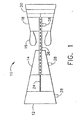
- FIG. 1 is a schematic illustration of an exemplary gas turbine engine 10 including a low pressure compressor 12, a high pressure compressor 14, and a combustor 16.
- Engine 10 also includes a high pressure turbine 18, and a low pressure turbine 20.
- Compressor 12 and turbine 20 are coupled by a first rotor shaft 24, and compressor 14 and turbine 18 are coupled by a second rotor shaft 26.
- Engine 10 includes a plurality of sensors 28 for monitoring parameters within engine 10. More specifically, for example, sensors 28 may be included in engine 10 that monitor a gas temperature, a gas pressure, an engine rotating speed, a fuel flow, and a stator vane position. Examples of sensor types are given by way of example only and are not limiting as to the type of sensor that may be used in gas turbine engine 10.
- engine 10 is a GE90 engine available from General Electric Aircraft Engines, Cincinnati, Ohio.
- FIG 2 is a data flow diagram of an exemplary engine control unit (ECU) 200 that may be used with engine 10 shown in Figure 1 .
- ECU 200 may be any suitable computing device or logic device, including, but not limited to, general purpose computers and/or dedicated single purpose computing devices, which may include single board, microprocessor based devices.
- ECU 200 includes monitoring logic 202 and a filter 204. In one embodiment, monitoring logic 202 and filter 204 are embodied in software stored in a non-volatile memory of ECU 200.
- ECU 200 is communicatively coupled to at least one sensor 28 and may be mounted remotely from engine 10 wherein each sensor 28 is coupled communicatively to ECU 200.
- Monitoring logic 202 receives input signals from at least one sensor 28 mounted on, or proximate to engine 10 that are representative of various engine operating parameters. Monitoring logic 202 also receives input signals from sensors 28 mounted on an airframe, such as but not limited to, engine power demand, and transmits at least a portion of each signal to filter 204. Monitoring logic 202 collects sensor data and formats sensor data in a form that can be used by filter 204 and a feature extractor 206 based on internal algorithms and an output from sensor 28. Filter 204 provides process operating conditions to a data historian 208 and a limit module 210 using collected sensor data from monitoring logic 202.
- Offscale failures Sensor failures in which the sensor output goes either high or low offscale are termed offscale failures and are relatively easy to detect.
- Onscale failures are those sensor failures wherein an output of the sensor remains within a normal range, but the sensor measurement is inaccurate. Onscale failures tend not to be associated with the transmitter itself but rather with the remainder of the measurement system.
- Some known sensors experience a failure mode such as a "soft failure", which is a sensor failure during particular modes of operation that reverts to correct operation when the operational stresses are reduced to a less stressful level.
- Onscale and soft failures may exhibit characteristic noise signatures on the sensor output signal that may be detected prior to a sensor offscale failure.
- ECU 200 is programmed to analyze sensor output signals provided by sensor 28, determine a noise component of the signal, trend the noise component historically, and store acceptable deviation ranges for the noise components. Determined data may be output through data communication line or channel 211.
- Feature extractor 206 assesses an output of monitoring logic 202 and determines metrics relative to the noise content of the data. Feature extractor 206 also develops a statistical analysis of the predicted and observed sensor output and noise signature.
- ECU 200 includes a comparator 212, data historian 208, and an isolator module 214.
- a result of historian 208 is coupled to limit module 210 through a data communication line or channel 215.
- Limit module 210 is communicatively coupled to comparator 212 through data line or channel 217.
- the result of historian 208 may be used to update limits provided by limit module 210 to comparator 212.
- Data historian 208 may store noise component signatures and signature trend data for sensor 28 output over time, where the sample interval may vary and be appropriate for the time constant or period for each sensor being monitored.
- historical noise signature data may be stored in a circular file, for a fixed period of time, before being overwritten with new data. Historical data may also be filtered prior to being stored and may also be compressed.
- H historiann 208 includes an extrapolation function, which projects current signatures and historical data into the future. Using an appropriate limit from limit module 210, and the projection provided to comparator 212 by the extrapolation function of historian 208, comparator 212 determines whether any of the projected noise signatures will be outside of the acceptable limits in the future. If the projected data falls outside of the acceptable limits, comparator 212 can output an alarm signal and/or maintenance message through output line 211.
- the projection made by historian 208 includes a sophisticated signal extrapolation method based on the current operating range of sensor 28, operational ranges of other related sensors, and engine operating conditions.
- Limit module 210 provides acceptable limits for noise metrics to comparator 212, based upon process operating conditions provided from filter 204. These limits may be updated over time based on historical trends available from historian 208.
- Comparator 212 assesses actual noise metrics provided from feature extractor 206 against the noise metric limits provided from limit module 210. Comparator 212 outputs alerts of impending failures for the sensors for which there were exceedances.
- isolator 214 Based on alerts generated by comparator 212, isolator 214 identifies a specific fault type that could account for the exceedance. In one embodiment, this function is performed by a neural network.
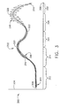
- Figure 3 is a graph 300 of an exemplary sensor output signal 302 that may be monitored by ECU 200 shown in Figure 2 .
- Graph 300 includes a y-axis 304 that may represent a magnitude of a monitored parameter received by monitoring logic 202.
- An x-axis 306 may represent an independent time parameter over which signal 302 may be monitored.
- Signal 302 includes a signal portion 308 that is proportional to the process parameter monitored by sensor 28 including offset errors, drift errors, linearity errors, and hysteresis errors.
- Signal 302 also includes a noise portion 310 that modulates signal portion 308 due to for example, electro-magnetic interference (EMI) pickup, sensor electronics soft failure, sensor element degradation, and /or a faulty or intermittent coupling of sensor 28 to the monitored parameter.
- EMI electro-magnetic interference
- a loose connection on a temperature sensor may allow a local difference between the monitored temperature, and the temperature at the sensing element.
- Such a loose connection may cause an intermittent deviation between the temperature at the sensing element, and the monitored temperature due to a vibration of the sensor or a temperature expansion of the sensor or process components.
- X-axis 306 includes a first period 312 wherein signal is 302 is represented as a relatively constant signal output from sensor 28.
- Signal 302 includes a constant magnitude signal portion 308, and a noise portion 310, which varies at a characteristic rate.
- the characteristic rate that noise portion 308 varies represents a unique signature for a particular sensor in a particular location.
- a second period 314 of x-axis 306 represents an increasing magnitude of the monitored parameter being monitored by sensor 28.
- noise portion 310 is indicated to increase in amplitude at a point 316 to an amplitude 318.
- noise portion 310 may also increase in rate and/or frequency.
- Graph 300 illustrates an exemplary response of sensor 28 to a varying process parameter.
- the changes in amplitude of noise portion 310 are illustrative of possible responses to varying ranges and conditions of operation of sensor 28.
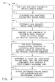
- FIG. 4 is a flow chart of an exemplary process 400 for detecting impending sensor failure by tracking sensor output signal noise which may be incorporated in a computer program executing within ECU 200 or other computer.
- the computer program may be any suitable compiled or interpreted program that includes but, is not limited to, languages such as Basic, Java, C, C++, or ladder logic.
- each monitored parameter signal may be updated to obtain 402 a current signal value.
- a current signal value is sampled from each sensor 28 for a predetermined duration, which is long enough to characterize the noise component of the signal.
- the monitored signals may be updated by directly reading analog or discrete sensors. Discrete or binary sensors may be characterized for noise and/or signal bounce such as may occur when switch contacts close momentarily due to vibration and/or impulse.
- Comparing 408 the current noise component to historical noise components that share similar range and operating condition parameters ensures comparison 408 is valid in that similar potential noise generating conditions are common to both compared 408 signals.
- Historical noise components may be projected or extrapolated into the future to determine predicted noise components, which are then compared 408 to the historical noise components to facilitate predicting an estimated time to failure.
- the current noise component is then added 410 to the historical database for future comparisons.
- a possible failure mode or modes is determined 412. Failure modes with known noise component symptoms are selected from a database of archived failure mode data that is associated with each symptom. The determined failure modes may be output 414 to a display, a computer, a control device, and/or another module of ECU 200.
- the above-described sensor failure detection system is cost-effective and highly reliable for determining an impending failure of a sensor. More specifically, the methods and systems described herein facilitate determining a soft failure and symptoms that may indicate a future failure of a sensor. In addition, the above-described methods and systems facilitate providing an early warning of impending sensor failure before traditional maintenance and testing means are able to provide a warning. As a result, the methods and systems described herein facilitate reducing maintenance costs in a cost-effective and reliable manner.
Landscapes
- Physics & Mathematics (AREA)
- Engineering & Computer Science (AREA)
- General Physics & Mathematics (AREA)
- Automation & Control Theory (AREA)
- Artificial Intelligence (AREA)
- Evolutionary Computation (AREA)
- Mathematical Physics (AREA)
- Testing Or Calibration Of Command Recording Devices (AREA)
- Testing Of Engines (AREA)
- Testing And Monitoring For Control Systems (AREA)
- Measuring Oxygen Concentration In Cells (AREA)
- Testing Electric Properties And Detecting Electric Faults (AREA)
Applications Claiming Priority (2)
| Application Number | Priority Date | Filing Date | Title |
|---|---|---|---|
| US375649 | 1999-08-17 | ||
| US10/375,649 US6741919B1 (en) | 2003-02-26 | 2003-02-26 | Methods and apparatus for detecting impending sensor failure |
Publications (3)
| Publication Number | Publication Date |
|---|---|
| EP1452936A2 EP1452936A2 (en) | 2004-09-01 |
| EP1452936A3 EP1452936A3 (en) | 2006-06-07 |
| EP1452936B1 true EP1452936B1 (en) | 2010-05-12 |
Family
ID=32312386
Family Applications (1)
| Application Number | Title | Priority Date | Filing Date |
|---|---|---|---|
| EP04251053A Expired - Lifetime EP1452936B1 (en) | 2003-02-26 | 2004-02-26 | Method for detecting an impending sensor failure |
Country Status (5)
| Country | Link |
|---|---|
| US (1) | US6741919B1 (enExample) |
| EP (1) | EP1452936B1 (enExample) |
| JP (1) | JP4646528B2 (enExample) |
| CN (1) | CN100489699C (enExample) |
| DE (1) | DE602004027098D1 (enExample) |
Families Citing this family (44)
| Publication number | Priority date | Publication date | Assignee | Title |
|---|---|---|---|---|
| US7729810B2 (en) * | 2002-04-01 | 2010-06-01 | Programable Control Services, Inc. | Electrical power distribution control systems and processes |
| US20050125104A1 (en) * | 2003-12-05 | 2005-06-09 | Wilson Thomas L. | Electrical power distribution control systems and processes |
| DE10235161A1 (de) * | 2002-08-01 | 2004-02-19 | Robert Bosch Gmbh | Sensor, Steuergerät und Verfahren zur Überwachung wenigstens eines Sensors |
| US6959607B2 (en) * | 2003-11-10 | 2005-11-01 | Honeywell International Inc. | Differential pressure sensor impulse line monitor |
| US7826954B2 (en) * | 2004-06-25 | 2010-11-02 | Honda Motor Co., Ltd. | System for monitoring sensor outputs of a gas turbine engine |
| US20060129301A1 (en) * | 2004-12-14 | 2006-06-15 | General Electric Company | Method and apparatus for assessing gas turbine acceleration capability |
| US7266464B2 (en) * | 2004-12-17 | 2007-09-04 | Texaco Inc. | Dynamic cut-off frequency varying filter |
| US7505844B2 (en) * | 2005-11-18 | 2009-03-17 | General Electric Company | Model-based iterative estimation of gas turbine engine component qualities |
| US7603222B2 (en) * | 2005-11-18 | 2009-10-13 | General Electric Company | Sensor diagnostics using embedded model quality parameters |
| US7584617B2 (en) * | 2006-03-17 | 2009-09-08 | Siemens Energy, Inc. | Monitoring health of a combustion dynamics sensing system |
| US8670876B2 (en) | 2006-04-04 | 2014-03-11 | Utilidata, Inc. | Electric power control system and process |
| US8390227B2 (en) | 2006-04-04 | 2013-03-05 | Utilidata, Inc. | Electric power control system and efficiency optimization process for a polyphase synchronous machine |
| US7369932B2 (en) * | 2006-05-04 | 2008-05-06 | Honeywell International, Inc. | System and method for turbine engine fault detection using discrete event system modeling |
| US7966804B2 (en) * | 2006-07-12 | 2011-06-28 | General Electric Company | Method and apparatus for testing gas turbine engines |
| DE102006041867B4 (de) * | 2006-09-06 | 2008-12-04 | Continental Automotive Gmbh | Verfahren und Vorrichtung zur Überwachung des Rauschens eines Sensors |
| US8320751B2 (en) | 2007-12-20 | 2012-11-27 | S.C. Johnson & Son, Inc. | Volatile material diffuser and method of preventing undesirable mixing of volatile materials |
| US20110192465A1 (en) * | 2010-02-09 | 2011-08-11 | Mission Communications, Llc | Vacuum Sewer Valve Fault Detection System |
| DE102010002504B4 (de) | 2010-03-02 | 2017-02-09 | TAKATA Aktiengesellschaft | Verfahren und Vorrichtung zum Überprüfen einer elektronischen Einrichtung |
| US8668381B2 (en) * | 2010-12-23 | 2014-03-11 | General Electric Company | High temperature electronic monitoring system |
| JP5776937B2 (ja) * | 2011-09-20 | 2015-09-09 | 株式会社ダイフク | 設備制御システム |
| JP5660394B2 (ja) * | 2011-09-20 | 2015-01-28 | 株式会社ダイフク | 設備制御システム |
| US8583597B2 (en) * | 2011-11-16 | 2013-11-12 | General Electric Company | System and method for on-site monitoring data archival |
| US8699660B2 (en) | 2012-04-24 | 2014-04-15 | General Electric Company | Liquid cooled thermal control system for an imaging detector |
| US9375183B2 (en) | 2012-06-28 | 2016-06-28 | General Electric Company | Method for monitoring sensor degradation, patient monitor, patient monitor system, physiological sensor, and computer program product for a patient monitor |
| US9211092B2 (en) * | 2013-01-03 | 2015-12-15 | Dexcom, Inc. | End of life detection for analyte sensors |
| US10066962B2 (en) | 2013-07-01 | 2018-09-04 | Battelle Energy Alliance, Llc | Apparatus, system, and method for sensor authentication |
| WO2015100632A1 (zh) | 2013-12-31 | 2015-07-09 | 西门子公司 | 燃气轮机运行参数检测故障的诊断方法 |
| US9383385B2 (en) | 2014-01-15 | 2016-07-05 | Pratt & Whitney Canada Corp. | System and method for speed sensor position detection in a multiple channel control system |
| US9606160B2 (en) * | 2014-03-05 | 2017-03-28 | GM Global Technology Operations LLC | Detection of stuck in range sensor and method |
| CN107111311B (zh) * | 2014-09-10 | 2020-01-14 | 西门子能源公司 | 利用稀疏编码方法的燃气涡轮机传感器故障检测 |
| US9784635B2 (en) * | 2015-06-29 | 2017-10-10 | General Electric Company | Systems and methods for detection of engine component conditions via external sensors |
| US9688262B1 (en) | 2016-06-23 | 2017-06-27 | Bendix Commercial Vehicle Systems Llc | Air monitoring system |
| JP2018205007A (ja) * | 2017-05-31 | 2018-12-27 | セイコーエプソン株式会社 | 回路装置、物理量測定装置、電子機器及び移動体 |
| CN107884656B (zh) * | 2017-12-25 | 2020-04-24 | 潍柴动力股份有限公司 | 一种可信度检测方法及装置 |
| US11158140B2 (en) * | 2019-03-19 | 2021-10-26 | General Electric Company | Signal response monitoring for turbine engines |
| JP7480172B2 (ja) * | 2019-04-25 | 2024-05-09 | アーベーベー・シュバイツ・アーゲー | 人工知能を用いたプロセス産業におけるプロダクションアカウンティングのための方法及びシステム |
| US11867397B2 (en) * | 2019-05-10 | 2024-01-09 | Electric Power Research Institute, Inc. | Gas turbine |
| CN110879152A (zh) * | 2019-12-02 | 2020-03-13 | 北京航天试验技术研究所 | 一种液体火箭发动机试验实时数据诊断策略 |
| US20210247753A1 (en) * | 2020-02-07 | 2021-08-12 | Kabushiki Kaisha Yaskawa Denki | State estimation device, system, and manufacturing method |
| EP4200619A4 (en) | 2020-08-18 | 2025-01-22 | Blackline Safety Corp. | APPARATUS AND METHODS FOR PREDICTING GAS SENSOR SENSITIVITY VARIATIONS |
| US12051289B2 (en) | 2020-12-17 | 2024-07-30 | Ge Infrastructure Technology Llc | Cloud-based acoustic monitoring, analysis, and diagnostic for power generation system |
| GB2603530B (en) | 2021-02-09 | 2023-03-15 | Rolls Royce Plc | Computer-implemented methods, apparatus, computer programs, and non-transitory computer readable storage mediums for determining a value of a parameter |
| US12399044B2 (en) * | 2022-11-11 | 2025-08-26 | Analog Devices, Inc. | Diagnostic coverage improvements in redundant sensor element fault detection architectures |
| US20250028312A1 (en) * | 2023-07-20 | 2025-01-23 | Saudi Arabian Oil Company | Gas monitoring detectors healthiness validation tool utilizing anomaly detection technique |
Family Cites Families (10)
| Publication number | Priority date | Publication date | Assignee | Title |
|---|---|---|---|---|
| DE3463582D1 (en) * | 1983-03-04 | 1987-06-11 | Cerberus Ag | Circuit arrangement for the interference level control of detectors, arranged in a danger detection device |
| DE69635726T2 (de) * | 1996-11-06 | 2006-09-14 | Zellweger Analytics Ltd., Poole | Überwachungsvorrichtung für elektrochemische Zellen |
| JP4308437B2 (ja) * | 1998-08-17 | 2009-08-05 | アスペン テクノロジー インコーポレイテッド | センサの性能確認装置および方法 |
| US6326758B1 (en) | 1999-12-15 | 2001-12-04 | Reliance Electric Technologies, Llc | Integrated diagnostics and control systems |
| US6314350B1 (en) | 1999-11-30 | 2001-11-06 | General Electric Company | Methods and apparatus for generating maintenance messages |
| US6505143B1 (en) * | 2000-01-20 | 2003-01-07 | General Electric Company | Machine protection system for rotating equipment and method |
| US6456928B1 (en) | 2000-12-29 | 2002-09-24 | Honeywell International Inc. | Prognostics monitor for systems that are subject to failure |
| JP3624847B2 (ja) * | 2001-03-23 | 2005-03-02 | トヨタ自動車株式会社 | 吸気酸素濃度センサの診断装置 |
| US6481210B1 (en) | 2001-05-16 | 2002-11-19 | Honeywell International, Inc. | Smart surge bleed valve system and method |
| US6439202B1 (en) | 2001-11-08 | 2002-08-27 | Cummins Inc. | Hybrid electronically controlled unit injector fuel system |
-
2003
- 2003-02-26 US US10/375,649 patent/US6741919B1/en not_active Expired - Lifetime
-
2004
- 2004-02-25 JP JP2004048945A patent/JP4646528B2/ja not_active Expired - Fee Related
- 2004-02-26 CN CNB2004100067811A patent/CN100489699C/zh not_active Expired - Lifetime
- 2004-02-26 DE DE602004027098T patent/DE602004027098D1/de not_active Expired - Lifetime
- 2004-02-26 EP EP04251053A patent/EP1452936B1/en not_active Expired - Lifetime
Also Published As
| Publication number | Publication date |
|---|---|
| US6741919B1 (en) | 2004-05-25 |
| EP1452936A3 (en) | 2006-06-07 |
| CN1542424A (zh) | 2004-11-03 |
| EP1452936A2 (en) | 2004-09-01 |
| CN100489699C (zh) | 2009-05-20 |
| DE602004027098D1 (de) | 2010-06-24 |
| JP2004257388A (ja) | 2004-09-16 |
| JP4646528B2 (ja) | 2011-03-09 |
Similar Documents
| Publication | Publication Date | Title |
|---|---|---|
| EP1452936B1 (en) | Method for detecting an impending sensor failure | |
| US6898554B2 (en) | Fault detection in a physical system | |
| CA2202771C (en) | Vibration monitoring system | |
| US6260004B1 (en) | Method and apparatus for diagnosing a pump system | |
| EP2175336A1 (en) | Adaptive Performance Model and Methods for System Maintenance | |
| EP1288644B1 (en) | Diagnostic method and system for turbine engines | |
| US20120330499A1 (en) | Acoustic diagnostic of fielded turbine engines | |
| JP5393693B2 (ja) | ガスタービンの運転を分析するための方法 | |
| EP2241726A2 (en) | A method for the repair of an engine and corresponding systems for monitoring this engine | |
| US6587737B2 (en) | Method for the monitoring of a plant | |
| EP2385378B1 (en) | Method to detect angle sensor performance degradation through dither monitoring | |
| EP1811133A2 (en) | Sensor diagnostics using a quality parameter model | |
| EP1860411A2 (en) | Electronic vibration sensor | |
| WO2002053405A2 (en) | Prognostics failure monitoring system for combustion engines | |
| US5680310A (en) | Method and apparatus for sensing a steady state engine condition using a trending algorithm | |
| US20220185503A1 (en) | System for monitoring the health of a helicopter | |
| US6502018B1 (en) | Method for diagnosis of equipment | |
| CN1161091A (zh) | 分析测量值的方法以及实施此方法的测量值分析器 | |
| US7249287B2 (en) | Methods and apparatus for providing alarm notification | |
| KR101119690B1 (ko) | 급탄기 제어장치 | |
| JP2004094631A (ja) | プラント機器の運用支援装置 | |
| US11131604B2 (en) | Turbocharger speed sensor diagnostic tool and method | |
| EP3955707A1 (en) | Method and system for predicting a failure probability of a component of an x-ray system | |
| US6959261B2 (en) | System for tracking and assessing changes in technical processes | |
| US20200122859A1 (en) | Predictive monitoring system and method |
Legal Events
| Date | Code | Title | Description |
|---|---|---|---|
| PUAI | Public reference made under article 153(3) epc to a published international application that has entered the european phase |
Free format text: ORIGINAL CODE: 0009012 |
|
| AK | Designated contracting states |
Kind code of ref document: A2 Designated state(s): AT BE BG CH CY CZ DE DK EE ES FI FR GB GR HU IE IT LI LU MC NL PT RO SE SI SK TR |
|
| AX | Request for extension of the european patent |
Extension state: AL HR LT LV MK |
|
| PUAL | Search report despatched |
Free format text: ORIGINAL CODE: 0009013 |
|
| AK | Designated contracting states |
Kind code of ref document: A3 Designated state(s): AT BE BG CH CY CZ DE DK EE ES FI FR GB GR HU IE IT LI LU MC NL PT RO SE SI SK TR |
|
| AX | Request for extension of the european patent |
Extension state: AL LT LV MK |
|
| RIC1 | Information provided on ipc code assigned before grant |
Ipc: G05B 23/00 20060101ALI20060424BHEP Ipc: G06F 17/40 20060101AFI20060424BHEP |
|
| 17P | Request for examination filed |
Effective date: 20061207 |
|
| 17Q | First examination report despatched |
Effective date: 20070112 |
|
| AKX | Designation fees paid |
Designated state(s): DE FR GB |
|
| GRAP | Despatch of communication of intention to grant a patent |
Free format text: ORIGINAL CODE: EPIDOSNIGR1 |
|
| GRAS | Grant fee paid |
Free format text: ORIGINAL CODE: EPIDOSNIGR3 |
|
| GRAA | (expected) grant |
Free format text: ORIGINAL CODE: 0009210 |
|
| AK | Designated contracting states |
Kind code of ref document: B1 Designated state(s): DE FR GB |
|
| REG | Reference to a national code |
Ref country code: GB Ref legal event code: FG4D |
|
| REF | Corresponds to: |
Ref document number: 602004027098 Country of ref document: DE Date of ref document: 20100624 Kind code of ref document: P |
|
| PLBE | No opposition filed within time limit |
Free format text: ORIGINAL CODE: 0009261 |
|
| STAA | Information on the status of an ep patent application or granted ep patent |
Free format text: STATUS: NO OPPOSITION FILED WITHIN TIME LIMIT |
|
| 26N | No opposition filed |
Effective date: 20110215 |
|
| REG | Reference to a national code |
Ref country code: DE Ref legal event code: R097 Ref document number: 602004027098 Country of ref document: DE Effective date: 20110214 |
|
| REG | Reference to a national code |
Ref country code: FR Ref legal event code: PLFP Year of fee payment: 13 |
|
| REG | Reference to a national code |
Ref country code: FR Ref legal event code: PLFP Year of fee payment: 14 |
|
| PGFP | Annual fee paid to national office [announced via postgrant information from national office to epo] |
Ref country code: DE Payment date: 20170227 Year of fee payment: 14 Ref country code: FR Payment date: 20170223 Year of fee payment: 14 |
|
| PGFP | Annual fee paid to national office [announced via postgrant information from national office to epo] |
Ref country code: GB Payment date: 20170227 Year of fee payment: 14 |
|
| REG | Reference to a national code |
Ref country code: DE Ref legal event code: R119 Ref document number: 602004027098 Country of ref document: DE |
|
| GBPC | Gb: european patent ceased through non-payment of renewal fee |
Effective date: 20180226 |
|
| REG | Reference to a national code |
Ref country code: FR Ref legal event code: ST Effective date: 20181031 |
|
| PG25 | Lapsed in a contracting state [announced via postgrant information from national office to epo] |
Ref country code: DE Free format text: LAPSE BECAUSE OF NON-PAYMENT OF DUE FEES Effective date: 20180901 |
|
| PG25 | Lapsed in a contracting state [announced via postgrant information from national office to epo] |
Ref country code: GB Free format text: LAPSE BECAUSE OF NON-PAYMENT OF DUE FEES Effective date: 20180226 Ref country code: FR Free format text: LAPSE BECAUSE OF NON-PAYMENT OF DUE FEES Effective date: 20180228 |