EP1452854A1 - Fail judging method for analysis and analyzer - Google Patents
Fail judging method for analysis and analyzer Download PDFInfo
- Publication number
- EP1452854A1 EP1452854A1 EP02781813A EP02781813A EP1452854A1 EP 1452854 A1 EP1452854 A1 EP 1452854A1 EP 02781813 A EP02781813 A EP 02781813A EP 02781813 A EP02781813 A EP 02781813A EP 1452854 A1 EP1452854 A1 EP 1452854A1
- Authority
- EP
- European Patent Office
- Prior art keywords
- acceleration
- current
- sample
- measurer
- change
- Prior art date
- Legal status (The legal status is an assumption and is not a legal conclusion. Google has not performed a legal analysis and makes no representation as to the accuracy of the status listed.)
- Granted
Links
Images


Classifications
-
- G—PHYSICS
- G01—MEASURING; TESTING
- G01N—INVESTIGATING OR ANALYSING MATERIALS BY DETERMINING THEIR CHEMICAL OR PHYSICAL PROPERTIES
- G01N27/00—Investigating or analysing materials by the use of electric, electrochemical, or magnetic means
- G01N27/26—Investigating or analysing materials by the use of electric, electrochemical, or magnetic means by investigating electrochemical variables; by using electrolysis or electrophoresis
- G01N27/28—Electrolytic cell components
- G01N27/30—Electrodes, e.g. test electrodes; Half-cells
- G01N27/327—Biochemical electrodes, e.g. electrical or mechanical details for in vitro measurements
- G01N27/3271—Amperometric enzyme electrodes for analytes in body fluids, e.g. glucose in blood
- G01N27/3274—Corrective measures, e.g. error detection, compensation for temperature or hematocrit, calibration
Definitions
- the present invention relates to a fail judging method to determine whether or not conditions for performing analysis are right in the analysis of a sample such as the measurement of the glucose level or cholesterol level in blood sample. It also relates to an analyzer for performing such a fail judging method.
- an electrochemical method which utilizes a biosensor provided with a reagent layer and a pair of electrodes.
- the sample is introduced to the reagent layer to cause the particular component in the sample to react with a component in the reagent layer.
- a voltage is applied to the reagent layer by utilizing the electrodes, and the current between the electrodes is measured.
- the current changes in accordance of the degree of the reaction. Further, the degree of reaction depends on the concentration of the particular component in the sample. The concentration of the particular component in the sample can be computed based on the measurements of the current.
- JP-B-2800981 discloses a method for detecting such a fail condition as described above.
- fail detection is performed by applying a voltage across a pair of electrodes of a biosensor and measuring the current between the electrodes.
- Fig. 8 shows the change of the current in this method.
- the current between the electrodes continues to increase after a time point indicated by the reference sign n1 at which a sample is introduced to the reagent layer.
- the current value exceeds a predetermined threshold value at the time point ta
- the rate at which the current increases immediately after the sample introduction depends on the amount of the sample introduced to the reagent layer. The smaller the amount of introduced sample is, the lower the rate at which the current increases.
- the current at a time point tb after a predetermined period T has elapsed since the time point ta is measured.
- the measured current is higher than a predetermined second threshold value as shown in the figure, it is determined that the amount of introduced sample is sufficient.
- the measured current is no higher than the second threshold value, it is determined that the amount of introduced sample is insufficient.
- fail determination is made based on the difference between two current values at predetermined time points.
- the determination is made based on the slope of the curve representing the current change at a predetermined time point, i.e., the rate of the current change.
- the rate of the change of the current flowing between the electrodes varies depending on the amount of introduced sample as noted above, the variation of the rate of the current change is not sufficiently large when the change of the amount of the sample introduced to the reagent layer is small. Therefore, in the prior art method, it is sometimes difficult to accurately determine whether or not the amount of introduced sample is sufficient.
- an excessively large value need be set as the second threshold value Th2. In such a case, however, there is a possibility that the amount of introduced sample is often determined to be insufficient although it is actually sufficient.
- a fail judging method to determine whether or not a predetermined condition necessary for performing analysis of a sample is satisfied by measuring an electro-physical quantity of the sample.
- the method comprises computing an acceleration of change of the electro-physical quantity and determining whether or not the predetermined condition is satisfied based on the acceleration.
- the "electro-physical quantity” refers to current, voltage or variation of charge for example.
- the “acceleration of change of the electro-physical quantity” refers to a variation, per small unit time, of the rate of change of the electro-physical quantity.
- the “rate of change of the electro-physical quantity” refers to a variation, per small unit time, of the electro-physical quantity.
- whether or not a required amount of the sample is supplied may be determined based on the acceleration.
- the fail determination is made based on the acceleration of change of an electro-physical quantity, and the acceleration is obtained by differentiating the rate of change of the electro-physical quantity. Therefore, even when the rate of change of the electro-physical quantity does not vary greatly in spite of the change of a condition for the analysis process, the acceleration of change of the electro-physical quantity may vary greatly. Therefore, the acceleration of change of the electro-physical quantity can be utilized as a parameter which varies greatly in response to a slight change of the condition for the sample analysis. Therefore, by utilizing the acceleration of change of the electro-physical quantity as a parameter for the fail determination, whether or not a predetermined condition for performing the sample analysis is satisfied can be determined more accurately than with the prior art method.
- a fail judging method to determine whether or not a predetermined condition necessary for performing analysis of a sample is satisfied, the analysis comprising causing the sample to react with a predetermined reagent while applying a voltage to the sample and the reagent to cause a current to flow and computing a concentration of a particular component in the sample based on the current.
- the method comprises computing an acceleration of change of the current at a time point at which the current reaches a predetermined value after the sample is introduced to the reagent layer, and determining whether or not the predetermined condition necessary for performing the analysis is satisfied based on the acceleration.
- the determination step may comprise comparing the acceleration with a predetermined threshold value and determining that the predetermined condition is not satisfied when the acceleration is smaller than the threshold value.
- an analyzer provided with a measurer for measuring an electro-physical quantity of a sample.
- the analyzer comprises an acceleration measurer for computing an acceleration of change of the electro-physical quantity measured by the measurer.
- the analyzer further comprises a determiner for determining whether or not a predetermined condition necessary for performing analysis is satisfied based on the acceleration of change of the electro-physical quantity computed by the acceleration measurer.
- the determination by the determiner is performed by comparing the acceleration with a predetermined threshold value.
- the analyzer further comprises a receptacle mount portion to which a receptacle for receiving the sample is removably mounted, and the measurer measures an electro-physical quantity of the sample received by the receptacle mounted to the receptacle mount portion.
- the measurer comprises a current measuring circuit
- the analyzer further comprises a processor for analyzing the sample based on a current measured by the current measuring circuit.
- the acceleration measurer computes an acceleration of change of the current measured by the current measuring circuit.
- the acceleration measurer computes velocities at which the current changes at two time points and then computes an acceleration of the current change at an intermediate time point between the two time points based on the difference between the velocities of the current change at the two time points.
- the processor determines that the predetermined condition is not satisfied by comparing the acceleration of the current change computed by the acceleration measurer with a predetermined threshold value.
- an analyzer comprising a mount portion for removably mounting a sensor including a reagent layer which effects a predetermined reaction with a sample introduced to the reagent layer and a pair of electrodes for applying voltage to the reagent layer, a current measurer for measuring a current flowing between the electrodes when a voltage is applied across the electrodes, and a processor for performing analysis of the sample based on the current measured by the current measurer.
- the analyzer further comprises an acceleration measurer for computing an acceleration of change of the current at a time point when the current reaches a predetermined value after the sample is introduced to the reagent layer, and the processor determines whether or not a predetermined condition necessary for performing the analysis of the sample is satisfied by comparing the acceleration computed by the acceleration measurer with a predetermined threshold value.
- the fail judging method provided in accordance with a first aspect or a second aspect of the invention can be performed properly, and the same advantages as described above can be obtained.
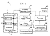
- Fig. 1 shows an embodiment of analyzer according to the present invention.
- a biosensor 2 as shown in Figs. 2 and 3 is utilized for the analyzer A of this embodiment.
- the biosensor 2 which functions to receive a sample, is an example of receptacle of the present invention.
- the biosensor 2 includes a substrate 24 having an upper surface on which a pair of electrodes 22a and 22b, and a reagent layer 23 are provided.
- the reagent layer 23 is arranged to cover respective upper surfaces of the electrodes 22a and 22b collectively or individually.
- the reagent layer 23 contains glucose oxidase and potassium ferricyanide as components to react with glucose in blood, for example.
- Portions around the reagent layer 23 and the electrodes 22a, 22b are covered with an insulating film 29. Aside of the insulating film 29 is provided terminals 27a and 27b electrically connected to the electrodes 22a and 22b.
- the spacer 25 is formed with a narrow slit 21 having a front end opening 21a.
- the cover 26 is formed with a hole 28 which allows part of the slit 21 to communicate with the outside.
- the analyzer A in this embodiment includes a biosensor mount portion 1, a processor 3, a biosensor detection circuit 40, a voltage supply circuit 41, a current measuring circuit 42, a temperature sensor 43, an acceleration measuring circuit 44 and a display 45.
- the biosensor mount portion 1 is an example of receptacle mount portion of the present invention and so structured that the biosensor 2 can be removably mounted to the biosensor mount portion.
- the terminals 27a and 27b of the biosensor 2 are electrically connected to the voltage supply circuit 41.
- the processor 3 which may comprise a CPU and an appropriate memory connected thereto, performs operation control at each of the units and data processing, which will be described later.
- the voltage supply circuit 41 applies a predetermined voltage across the paired electrodes 22a and 22b of the biosensor 2 under the control of the processor 3.
- the current measuring circuit 42 measures the current between the electrodes 23a and 22b and outputs the measurement data to the processor 3 and the acceleration measuring circuit 44.
- the acceleration measuring circuit 44 functions to compute the acceleration of change of the current flowing between the electrodes 22a and 22b based on the current values measured by the current measuring circuit 42. The method of computing the acceleration will be described later in detail.
- the acceleration measuring circuit 44 may be provided as an integral part of the processor 3.
- the biosensor detection circuit 40 detects the biosensor 2 when the biosensor is properly mounted to the biosensor mount portion 1 and outputs a signal to that effect to the processor 3.
- the temperature sensor 43 measures the ambient temperature of the biosensor 2 and outputs the measurement data to the processor 3.
- the display 45 can display an intended image under the control of the processor 3 and may comprise a liquid crystal display or a CRT, for example.
- the temperature sensor 43 measures the temperature and the temperature data is stored in the processor 3 (S2). The temperature data will be utilized later for temperature compensation of the glucose level measurement.
- the processor 3 drives the voltage supply circuit 41 to apply a voltage of e.g. about 500mV across the electrodes 22a and 22b of the biosensor 2 (S3). Specifically, as shown in Fig. 5A, voltage is applied across the electrodes 22a and 22b twice, i.e. for a period T1 and for a period T2. As will be described later, the first voltage application for the period T1 is performed for the fail determination, whereas the second voltage application for the period T2 is performed for the glucose level measurement.
- potassium ferrocyanide When a voltage is applied in this state, potassium ferrocyanide is oxidized to its original state, i.e., potassium ferricyanide, and electrons released in the reaction are supplied to the paired electrodes 22a and 2b, whereby current is detected between the electrodes 22a and 22b.
- Fig. 6 illustrates the change of the current.
- the processor 3 determines that the blood was introduced (S4: YES). This time point t3 is set as a reference time point for the fail determination.
- the current measuring circuit 42 continues to measure the current, and the acceleration measuring circuit 44 computes the acceleration of the current change at the reference time point t3 based on a current value I 3 at the time point t3 (which is equal to the first threshold value Th1), and respective current values I 1 and I 5 at time points t1 and t5 which are slightly (e.g. about 0.2 seconds) before or after the time point t3 (S5).
- the slope of the curve of the current at an intermediate time point t2 i.e. , the rate V 2 of the current change at the time point t2 is computed by dividing the difference Ia between the current value I 1 at the time point t1 and the current value I 3 at the time point t3 by the time interval between the time points t1 and t3.
- the rate V 4 of the current change at an intermediate time point t4 is computed by dividing the difference Ib between the current values at the time point t3 and t5 by the time interval between the time points t3 and t5.
- the difference between the rate of the current change V 2 at the time point t2 and the rate of the current change V 4 at the time point t4 is divided by the time interval between these time points, whereby the acceleration a 3 of the current change at the reference time point t3 is computed.
- the processor 3 compares the acceleration a 3 with a predetermined second threshold value. When the acceleration a 3 is found to be no larger than the second threshold value as a result of the comparison (S6: NO), the processor 3 determines that the amount of blood introduced to the reagent layer 23 is insufficient and causes the display 45 to display a notice to that effect (S9). The processor then ends the process.
- the acceleration of the current change when the minimum amount of blood necessary for the accurate glucose level measurement is introduced is graphically represented by the curve indicated by the reference sign L1 in Fig. 7.
- the acceleration of the current change when the amount of introduced blood is insufficient is graphically represented by the dashed curve indicated by the reference sign L2 in the figure.
- the acceleration of the current change in the case where the amount of introduced blood is insufficient is smaller over a relatively long period after the time point t0 than in the case where the amount of introduced blood is sufficient.
- the difference of the acceleration between the two cases is remarkable particularly at or around the time point at which the acceleration of the current change in the case where the amount of introduced blood is sufficient becomes maximum.
- the maximum value Th2 of the acceleration in the curve L1, which is reached at the time point t3, is utilized as the above-noted second threshold value. Therefore, when the acceleration a 3 of the current change at the time point t3, which is computed by the acceleration measuring circuit 44, is smaller than the second threshold value Th2, it is determined that the amount of introduced blood is insufficient.
- the acceleration a 3 of the current change at the time point t3 is a value in a period in which the current varies largely in response to even a slight change of the amount of introduced blood. Therefore, when the amount of introduced blood is insufficient, the acceleration a 3 exhibits a value far below the second threshold value Th2. Thus, the insufficiency of the amount of introduced blood can be detected accurately. In this method, therefore, an excessively large value need not be set as the second threshold value Th2. Therefore, it is possible to lessen the possibility that the amount of introduced blood is erroneously determined to be insufficient although it is in fact sufficient.
- the processor 3 When the acceleration a 3 at the time point t3 is larger than the second threshold value Th2 (S6: YES), the processor 3 performs control for the glucose level measurement (S7) and performs operation to cause the display 45 to display the result (S8).
- a predetermined period e.g. one second
- voltage application across the electrodes 22a and 22b is interrupted so that the reaction of glucose in blood with the reagent layer 23 is promoted.
- a time point t7 after a predetermined period e.g.
- the present invention is not limited to the foregoing embodiment.
- the specific structure of each step of the fail determination method in the analysis process may be modified in various ways.
- the specific structure of each part of the analyzer according to the present invention may be modified in various ways.
- accelerations at a plurality of time points may be computed. In this case, it may be determined that a fail condition exists when at least one of the accelerations is no larger than a predetermined threshold value. Further, acceleration at any time point may appropriately be utilized for the fail determination.
- the acceleration value of the current change or the threshold value may appropriately be corrected in view of the ambient temperature or other conditions, and the fail determination may be performed based on the corrected value.
- the acceleration of the current change varies depending on not only the amount of the sample introduced to the reagent layer but also other conditions of each electrode or the reagent layer. Therefore, the acceleration of the current change may become smaller than the threshold value due to such other conditions.
- the fail determination method according to the present invention can also detect a failure in such a case. Therefore, with the fail determination method according to the present invention, it is possible to determine whether or not the conditions necessary for performing the analysis are satisfied as well as whether or not the amount of the sample introduced to the reagent layer is sufficient.
- the electro-physical quantity of the sample to be measured is not limited to current, and other electro-physical quantities such as voltage or variation of charge may be utilized.
- the reagent layer use may be made of one that reacts with cholesterol or lactic acid for measuring the concentration of these components..
- the reagent layer may not be used. Therefore, instead of the above-noted biosensor, a member which is not provided with a reagent layer may be used as the receptacle for receiving the sample. Moreover, the receptacle itself may not be provided with a terminal for measuring current, for example.
Landscapes
- Health & Medical Sciences (AREA)
- Chemical & Material Sciences (AREA)
- Hematology (AREA)
- Life Sciences & Earth Sciences (AREA)
- Analytical Chemistry (AREA)
- Chemical Kinetics & Catalysis (AREA)
- Electrochemistry (AREA)
- Physics & Mathematics (AREA)
- Molecular Biology (AREA)
- Biochemistry (AREA)
- General Health & Medical Sciences (AREA)
- General Physics & Mathematics (AREA)
- Immunology (AREA)
- Pathology (AREA)
- Investigating Or Analysing Biological Materials (AREA)
- Automatic Analysis And Handling Materials Therefor (AREA)
Abstract
Description
Claims (14)
- A fail judging method to determine whether or not a predetermined condition necessary for performing analysis of a sample is satisfied by measuring an electro-physical quantity of the sample;
wherein the method comprises computing an acceleration of change of the electro-physical quantity and determining whether or not the predetermined condition is satisfied based on the acceleration. - The fail judging method according to claim 1, wherein the electro-physical quantity is a current that flows when a voltage is applied to the sample.
- The fail judging method according to claim 1, wherein whether or not a required amount of the sample is supplied is determined based on the acceleration.
- A fail judging method to determine whether or not a predetermined condition necessary for performing analysis of a sample is satisfied, the analysis comprising: causing the sample to react with a predetermined reagent while applying a voltage to the sample and the reagent to cause a current to flow and computing a concentration of a particular component in the sample based on the current, wherein the method comprises:computing an acceleration of change of the current at a time point at which the current reaches a predetermined value after the sample is introduced to the reagent layer; anddetermining whether or not the predetermined condition necessary for performing the analysis is satisfied based on the acceleration.
- The fail judging method according to claim 4, wherein the determination step comprises comparing the acceleration with a predetermined threshold value and determining that the predetermined condition is not satisfied when the acceleration is smaller than the threshold value.
- An analyzer provided with a measurer for measuring an electro-physical quantity of a sample,
wherein the analyzer comprises an acceleration measurer for computing an acceleration of change of the electro-physical quantity measured by the measurer. - The analyzer according to claim 6, further comprising a determiner for determining whether or not a predetermined condition necessary for performing analysis is satisfied based on the acceleration of change of the electro-physical quantity computed by the acceleration measurer.
- The analyzer according to claim 7, wherein the determination by the determiner is performed by comparing the acceleration with a predetermined threshold value.
- The analyzer according to claim 6, further comprising a receptacle mount portion to which a receptacle for receiving the sample is removably mounted,
wherein the measurer measures an electro-physical quantity of the sample received by the receptacle mounted to the receptacle mount portion. - The analyzer according to claim 6, wherein the measurer comprises a current measuring circuit, and wherein the analyzer further comprises a processor for analyzing the sample based on current measured by the current measuring circuit.
- The analyzer according to claim 10, wherein the acceleration measurer computes an acceleration of change of the current measured by the current measuring circuit.
- The analyzer according to claim 11, wherein the acceleration measurer computes velocities at two time points at which the current changes and then computes an acceleration of the current change at an intermediate time point between the two time points based on a difference between the velocities of the current change at said two time points.
- The analyzer according to claim 11, wherein the processor determines that the predetermined condition is not satisfied by comparing the acceleration of the current change computed by the acceleration measurer with a predetermined threshold value.
- An analyzer comprising: a mount portion for removably mounting a sensor including a reagent layer which effects a predetermined reaction with a sample introduced to the reagent layer, and a pair of electrodes for applying a voltage to the reagent layer;
a current measurer for measuring a current flowing between the electrodes when a voltage is applied across the electrodes; and
a processor for performing analysis of the sample based on the current measured by the current measurer;
wherein the analyzer further comprises an acceleration measurer for computing an acceleration of change of the current at a time point when the current reaches a predetermined value after the sample is introduced to the reagent layer; and
wherein the processor determines whether or not a predetermined condition necessary for performing the analysis of the sample is satisfied by comparing the acceleration computed by the acceleration measurer with a predetermined threshold value.
Applications Claiming Priority (3)
| Application Number | Priority Date | Filing Date | Title |
|---|---|---|---|
| JP2001355324 | 2001-11-20 | ||
| JP2001355324 | 2001-11-20 | ||
| PCT/JP2002/012035 WO2003044514A1 (en) | 2001-11-20 | 2002-11-18 | Fail judging method for analysis and analyzer |
Publications (3)
| Publication Number | Publication Date |
|---|---|
| EP1452854A1 true EP1452854A1 (en) | 2004-09-01 |
| EP1452854A4 EP1452854A4 (en) | 2010-02-17 |
| EP1452854B1 EP1452854B1 (en) | 2015-02-25 |
Family
ID=19167047
Family Applications (1)
| Application Number | Title | Priority Date | Filing Date |
|---|---|---|---|
| EP02781813.7A Expired - Lifetime EP1452854B1 (en) | 2001-11-20 | 2002-11-18 | Fail judging method for analysis and analyzer |
Country Status (6)
| Country | Link |
|---|---|
| US (1) | US7083712B2 (en) |
| EP (1) | EP1452854B1 (en) |
| JP (1) | JP4260017B2 (en) |
| CN (1) | CN1271406C (en) |
| AU (1) | AU2002349662A1 (en) |
| WO (1) | WO2003044514A1 (en) |
Cited By (4)
| Publication number | Priority date | Publication date | Assignee | Title |
|---|---|---|---|---|
| WO2007014231A1 (en) * | 2005-07-26 | 2007-02-01 | Bayer Healthcare Llc | Method and system for checking an electromechanical biosensor |
| EP1746413A3 (en) * | 2005-07-19 | 2007-02-21 | Hypoguard Limited | Electrochemical Biosensor and method of manufacture |
| EP2437056A1 (en) * | 2006-10-05 | 2012-04-04 | Lifescan Scotland Ltd | Methods for determining the presence of a sufficient quantity of fluid sample on a test strip |
| US9046480B2 (en) | 2006-10-05 | 2015-06-02 | Lifescan Scotland Limited | Method for determining hematocrit corrected analyte concentrations |
Families Citing this family (94)
| Publication number | Priority date | Publication date | Assignee | Title |
|---|---|---|---|---|
| US6036924A (en) | 1997-12-04 | 2000-03-14 | Hewlett-Packard Company | Cassette of lancet cartridges for sampling blood |
| US6391005B1 (en) | 1998-03-30 | 2002-05-21 | Agilent Technologies, Inc. | Apparatus and method for penetration with shaft having a sensor for sensing penetration depth |
| US8641644B2 (en) | 2000-11-21 | 2014-02-04 | Sanofi-Aventis Deutschland Gmbh | Blood testing apparatus having a rotatable cartridge with multiple lancing elements and testing means |
| DE10057832C1 (en) | 2000-11-21 | 2002-02-21 | Hartmann Paul Ag | Blood analysis device has syringe mounted in casing, annular mounting carrying needles mounted behind test strip and being swiveled so that needle can be pushed through strip and aperture in casing to take blood sample |
| AU2002348683A1 (en) | 2001-06-12 | 2002-12-23 | Pelikan Technologies, Inc. | Method and apparatus for lancet launching device integrated onto a blood-sampling cartridge |
| US7041068B2 (en) | 2001-06-12 | 2006-05-09 | Pelikan Technologies, Inc. | Sampling module device and method |
| US7344507B2 (en) | 2002-04-19 | 2008-03-18 | Pelikan Technologies, Inc. | Method and apparatus for lancet actuation |
| US9795747B2 (en) | 2010-06-02 | 2017-10-24 | Sanofi-Aventis Deutschland Gmbh | Methods and apparatus for lancet actuation |
| US7981056B2 (en) | 2002-04-19 | 2011-07-19 | Pelikan Technologies, Inc. | Methods and apparatus for lancet actuation |
| WO2002100460A2 (en) | 2001-06-12 | 2002-12-19 | Pelikan Technologies, Inc. | Electric lancet actuator |
| WO2002100461A2 (en) | 2001-06-12 | 2002-12-19 | Pelikan Technologies, Inc. | Method and apparatus for improving success rate of blood yield from a fingerstick |
| US7682318B2 (en) | 2001-06-12 | 2010-03-23 | Pelikan Technologies, Inc. | Blood sampling apparatus and method |
| US9427532B2 (en) | 2001-06-12 | 2016-08-30 | Sanofi-Aventis Deutschland Gmbh | Tissue penetration device |
| US9226699B2 (en) | 2002-04-19 | 2016-01-05 | Sanofi-Aventis Deutschland Gmbh | Body fluid sampling module with a continuous compression tissue interface surface |
| US8337419B2 (en) | 2002-04-19 | 2012-12-25 | Sanofi-Aventis Deutschland Gmbh | Tissue penetration device |
| US7537571B2 (en) | 2001-06-12 | 2009-05-26 | Pelikan Technologies, Inc. | Integrated blood sampling analysis system with multi-use sampling module |
| CA2448902C (en) | 2001-06-12 | 2010-09-07 | Pelikan Technologies, Inc. | Self optimizing lancing device with adaptation means to temporal variations in cutaneous properties |
| US7344894B2 (en) | 2001-10-16 | 2008-03-18 | Agilent Technologies, Inc. | Thermal regulation of fluidic samples within a diagnostic cartridge |
| US9248267B2 (en) | 2002-04-19 | 2016-02-02 | Sanofi-Aventis Deustchland Gmbh | Tissue penetration device |
| US9795334B2 (en) | 2002-04-19 | 2017-10-24 | Sanofi-Aventis Deutschland Gmbh | Method and apparatus for penetrating tissue |
| US8221334B2 (en) | 2002-04-19 | 2012-07-17 | Sanofi-Aventis Deutschland Gmbh | Method and apparatus for penetrating tissue |
| US8267870B2 (en) | 2002-04-19 | 2012-09-18 | Sanofi-Aventis Deutschland Gmbh | Method and apparatus for body fluid sampling with hybrid actuation |
| US7374544B2 (en) | 2002-04-19 | 2008-05-20 | Pelikan Technologies, Inc. | Method and apparatus for penetrating tissue |
| US7491178B2 (en) | 2002-04-19 | 2009-02-17 | Pelikan Technologies, Inc. | Method and apparatus for penetrating tissue |
| US8784335B2 (en) | 2002-04-19 | 2014-07-22 | Sanofi-Aventis Deutschland Gmbh | Body fluid sampling device with a capacitive sensor |
| US7141058B2 (en) | 2002-04-19 | 2006-11-28 | Pelikan Technologies, Inc. | Method and apparatus for a body fluid sampling device using illumination |
| US7229458B2 (en) | 2002-04-19 | 2007-06-12 | Pelikan Technologies, Inc. | Method and apparatus for penetrating tissue |
| US7297122B2 (en) | 2002-04-19 | 2007-11-20 | Pelikan Technologies, Inc. | Method and apparatus for penetrating tissue |
| US7547287B2 (en) | 2002-04-19 | 2009-06-16 | Pelikan Technologies, Inc. | Method and apparatus for penetrating tissue |
| US7563232B2 (en) | 2002-04-19 | 2009-07-21 | Pelikan Technologies, Inc. | Method and apparatus for penetrating tissue |
| US7909778B2 (en) | 2002-04-19 | 2011-03-22 | Pelikan Technologies, Inc. | Method and apparatus for penetrating tissue |
| US9314194B2 (en) | 2002-04-19 | 2016-04-19 | Sanofi-Aventis Deutschland Gmbh | Tissue penetration device |
| US7582099B2 (en) | 2002-04-19 | 2009-09-01 | Pelikan Technologies, Inc | Method and apparatus for penetrating tissue |
| US8702624B2 (en) | 2006-09-29 | 2014-04-22 | Sanofi-Aventis Deutschland Gmbh | Analyte measurement device with a single shot actuator |
| US7481776B2 (en) | 2002-04-19 | 2009-01-27 | Pelikan Technologies, Inc. | Method and apparatus for penetrating tissue |
| US7674232B2 (en) | 2002-04-19 | 2010-03-09 | Pelikan Technologies, Inc. | Method and apparatus for penetrating tissue |
| US7410468B2 (en) | 2002-04-19 | 2008-08-12 | Pelikan Technologies, Inc. | Method and apparatus for penetrating tissue |
| US7892183B2 (en) | 2002-04-19 | 2011-02-22 | Pelikan Technologies, Inc. | Method and apparatus for body fluid sampling and analyte sensing |
| US8579831B2 (en) | 2002-04-19 | 2013-11-12 | Sanofi-Aventis Deutschland Gmbh | Method and apparatus for penetrating tissue |
| US7291117B2 (en) | 2002-04-19 | 2007-11-06 | Pelikan Technologies, Inc. | Method and apparatus for penetrating tissue |
| US7226461B2 (en) | 2002-04-19 | 2007-06-05 | Pelikan Technologies, Inc. | Method and apparatus for a multi-use body fluid sampling device with sterility barrier release |
| US7524293B2 (en) | 2002-04-19 | 2009-04-28 | Pelikan Technologies, Inc. | Method and apparatus for penetrating tissue |
| US7976476B2 (en) | 2002-04-19 | 2011-07-12 | Pelikan Technologies, Inc. | Device and method for variable speed lancet |
| US7648468B2 (en) | 2002-04-19 | 2010-01-19 | Pelikon Technologies, Inc. | Method and apparatus for penetrating tissue |
| US7232451B2 (en) | 2002-04-19 | 2007-06-19 | Pelikan Technologies, Inc. | Method and apparatus for penetrating tissue |
| US7331931B2 (en) | 2002-04-19 | 2008-02-19 | Pelikan Technologies, Inc. | Method and apparatus for penetrating tissue |
| US7901362B2 (en) | 2002-04-19 | 2011-03-08 | Pelikan Technologies, Inc. | Method and apparatus for penetrating tissue |
| US7717863B2 (en) | 2002-04-19 | 2010-05-18 | Pelikan Technologies, Inc. | Method and apparatus for penetrating tissue |
| US7371247B2 (en) | 2002-04-19 | 2008-05-13 | Pelikan Technologies, Inc | Method and apparatus for penetrating tissue |
| KR100468916B1 (en) * | 2002-05-01 | 2005-02-02 | 삼성전자주식회사 | Air conditioner and control method thereof |
| US8574895B2 (en) | 2002-12-30 | 2013-11-05 | Sanofi-Aventis Deutschland Gmbh | Method and apparatus using optical techniques to measure analyte levels |
| ES2490740T3 (en) | 2003-06-06 | 2014-09-04 | Sanofi-Aventis Deutschland Gmbh | Apparatus for blood fluid sampling and analyte detection |
| WO2006001797A1 (en) | 2004-06-14 | 2006-01-05 | Pelikan Technologies, Inc. | Low pain penetrating |
| US7604592B2 (en) | 2003-06-13 | 2009-10-20 | Pelikan Technologies, Inc. | Method and apparatus for a point of care device |
| US8275437B2 (en) | 2003-08-01 | 2012-09-25 | Dexcom, Inc. | Transcutaneous analyte sensor |
| US8845536B2 (en) * | 2003-08-01 | 2014-09-30 | Dexcom, Inc. | Transcutaneous analyte sensor |
| US7774145B2 (en) * | 2003-08-01 | 2010-08-10 | Dexcom, Inc. | Transcutaneous analyte sensor |
| US8160669B2 (en) * | 2003-08-01 | 2012-04-17 | Dexcom, Inc. | Transcutaneous analyte sensor |
| US7920906B2 (en) | 2005-03-10 | 2011-04-05 | Dexcom, Inc. | System and methods for processing analyte sensor data for sensor calibration |
| EP1671096A4 (en) | 2003-09-29 | 2009-09-16 | Pelikan Technologies Inc | METHOD AND APPARATUS FOR AN IMPROVED SAMPLING INTERFERENCE DEVICE |
| EP1680014A4 (en) | 2003-10-14 | 2009-01-21 | Pelikan Technologies Inc | METHOD AND APPARATUS PROVIDING A VARIABLE USER INTERFACE |
| US9247900B2 (en) | 2004-07-13 | 2016-02-02 | Dexcom, Inc. | Analyte sensor |
| WO2005065414A2 (en) | 2003-12-31 | 2005-07-21 | Pelikan Technologies, Inc. | Method and apparatus for improving fluidic flow and sample capture |
| US7822454B1 (en) | 2005-01-03 | 2010-10-26 | Pelikan Technologies, Inc. | Fluid sampling device with improved analyte detecting member configuration |
| US8828203B2 (en) | 2004-05-20 | 2014-09-09 | Sanofi-Aventis Deutschland Gmbh | Printable hydrogels for biosensors |
| EP1765194A4 (en) | 2004-06-03 | 2010-09-29 | Pelikan Technologies Inc | METHOD AND APPARATUS FOR MANUFACTURING A DEVICE FOR SAMPLING LIQUIDS |
| JP4805259B2 (en) * | 2004-06-17 | 2011-11-02 | バイエル・ヘルスケア・エルエルシー | Detection of incomplete filling of biosensor |
| US8989833B2 (en) | 2004-07-13 | 2015-03-24 | Dexcom, Inc. | Transcutaneous analyte sensor |
| US8565848B2 (en) | 2004-07-13 | 2013-10-22 | Dexcom, Inc. | Transcutaneous analyte sensor |
| US8652831B2 (en) | 2004-12-30 | 2014-02-18 | Sanofi-Aventis Deutschland Gmbh | Method and apparatus for analyte measurement test time |
| WO2007026683A1 (en) * | 2005-09-02 | 2007-03-08 | Arkray, Inc. | Method for detecting sample supply condition, and analyzer |
| US8529751B2 (en) | 2006-03-31 | 2013-09-10 | Lifescan, Inc. | Systems and methods for discriminating control solution from a physiological sample |
| US20100021940A1 (en) * | 2006-04-12 | 2010-01-28 | Astrazeneca Ab | Method for Determining the Activity of a Protease in a Sample |
| MX2008013974A (en) * | 2006-05-03 | 2008-11-14 | Bayer Healthcare Llc | INSUFFICIENT FILLING DETECTION SYSTEM FOR AN ELECTROCHEMICAL BIOSENSOR. |
| US8882987B2 (en) * | 2006-07-26 | 2014-11-11 | Panasonic Healthcare Co., Ltd. | Biosensor measurement system and method for detecting abnormal waveform in biosensor |
| EP2053388B1 (en) * | 2006-07-26 | 2016-08-31 | Panasonic Healthcare Holdings Co., Ltd. | Biosensor measuring system and measuring method |
| JP4873170B2 (en) * | 2007-06-06 | 2012-02-08 | グンゼ株式会社 | Measurement display to which a biosensor is connected |
| US8778168B2 (en) | 2007-09-28 | 2014-07-15 | Lifescan, Inc. | Systems and methods of discriminating control solution from a physiological sample |
| US8000918B2 (en) * | 2007-10-23 | 2011-08-16 | Edwards Lifesciences Corporation | Monitoring and compensating for temperature-related error in an electrochemical sensor |
| EP2211170A1 (en) * | 2007-10-31 | 2010-07-28 | ARKRAY, Inc. | Analysis tool, analyzer, sample shortage detection method, and sample analysis method |
| US8603768B2 (en) * | 2008-01-17 | 2013-12-10 | Lifescan, Inc. | System and method for measuring an analyte in a sample |
| US7730782B2 (en) * | 2008-04-04 | 2010-06-08 | Panasonic Corporation | Sensor device |
| US8322214B2 (en) | 2008-04-04 | 2012-12-04 | Panasonic Corporation | Sensor device |
| EP2265324B1 (en) | 2008-04-11 | 2015-01-28 | Sanofi-Aventis Deutschland GmbH | Integrated analyte measurement system |
| US8551320B2 (en) | 2008-06-09 | 2013-10-08 | Lifescan, Inc. | System and method for measuring an analyte in a sample |
| US9375169B2 (en) | 2009-01-30 | 2016-06-28 | Sanofi-Aventis Deutschland Gmbh | Cam drive for managing disposable penetrating member actions with a single motor and motor and control system |
| IL209760A (en) | 2009-12-11 | 2015-05-31 | Lifescan Scotland Ltd | Fill sufficiency method and system |
| US8965476B2 (en) | 2010-04-16 | 2015-02-24 | Sanofi-Aventis Deutschland Gmbh | Tissue penetration device |
| US9301753B2 (en) | 2010-09-30 | 2016-04-05 | Ethicon Endo-Surgery, Llc | Expandable tissue thickness compensator |
| CN103261881B (en) * | 2011-02-02 | 2015-01-21 | 松下健康医疗控股株式会社 | Biological sample measuring device |
| JP5783891B2 (en) * | 2011-12-12 | 2015-09-24 | グンゼ株式会社 | Measurement display device |
| JP2014149218A (en) * | 2013-02-01 | 2014-08-21 | Hitachi Automotive Systems Ltd | Inertial force detection device |
| CA2935945A1 (en) * | 2014-01-10 | 2015-07-16 | Ascensia Diabetes Care Holdings Ag | Methods and apparatus for representing blood glucose variation graphically |
| EP4610782A3 (en) | 2017-10-26 | 2025-10-22 | Verily Life Sciences LLC | Two-phase deployment-initiated wakeup mechanism for body-mountable electronic device |
Family Cites Families (18)
| Publication number | Priority date | Publication date | Assignee | Title |
|---|---|---|---|---|
| US3786352A (en) * | 1972-04-17 | 1974-01-15 | Beckman Instruments Inc | Rate analysis system with overrange signal detection circuit for identifying false signals |
| US4626413A (en) * | 1984-01-10 | 1986-12-02 | Anatel Instrument Corporation | Instrument for measurement of the organic carbon content of water |
| CH669851A5 (en) * | 1986-03-06 | 1989-04-14 | Tecan Ag | |
| JPS6423150A (en) * | 1987-07-17 | 1989-01-25 | Daikin Ind Ltd | Concentration measuring instrument |
| JPS6421350A (en) * | 1987-07-17 | 1989-01-24 | Hitachi Ltd | Remover of carbonic acid dissolved in water |
| US5389097A (en) * | 1990-05-25 | 1995-02-14 | Novatec Medical Products, Inc. | Enhanced monitoring device for surgical gloves and other barriers |
| JPH0820412B2 (en) * | 1990-07-20 | 1996-03-04 | 松下電器産業株式会社 | Quantitative analysis method and device using disposable sensor |
| JPH04361157A (en) | 1991-06-07 | 1992-12-14 | Kyoto Denshi Kogyo Kk | Automatic end point detection method in titrator |
| JP3189416B2 (en) | 1992-09-25 | 2001-07-16 | 松下電器産業株式会社 | Liquid component measuring device |
| US5352351A (en) * | 1993-06-08 | 1994-10-04 | Boehringer Mannheim Corporation | Biosensing meter with fail/safe procedures to prevent erroneous indications |
| JP3516069B2 (en) * | 1995-08-03 | 2004-04-05 | アークレイ株式会社 | How to measure glucose concentration |
| JP3482760B2 (en) * | 1996-03-29 | 2004-01-06 | Jfeスチール株式会社 | How to measure plating weight |
| US6069011A (en) * | 1997-12-10 | 2000-05-30 | Umm Electronics, Inc. | Method for determining the application of a sample fluid on an analyte strip using first and second derivatives |
| US6175752B1 (en) * | 1998-04-30 | 2001-01-16 | Therasense, Inc. | Analyte monitoring device and methods of use |
| CA2305922C (en) * | 1999-08-02 | 2005-09-20 | Bayer Corporation | Improved electrochemical sensor design |
| JP2001066274A (en) | 1999-08-27 | 2001-03-16 | Omron Corp | Evaluation method of biosensor |
| US6560471B1 (en) * | 2001-01-02 | 2003-05-06 | Therasense, Inc. | Analyte monitoring device and methods of use |
| US6541266B2 (en) * | 2001-02-28 | 2003-04-01 | Home Diagnostics, Inc. | Method for determining concentration of an analyte in a test strip |
-
2002
- 2002-11-18 EP EP02781813.7A patent/EP1452854B1/en not_active Expired - Lifetime
- 2002-11-18 AU AU2002349662A patent/AU2002349662A1/en not_active Abandoned
- 2002-11-18 JP JP2003546096A patent/JP4260017B2/en not_active Expired - Lifetime
- 2002-11-18 CN CN02823075.2A patent/CN1271406C/en not_active Expired - Lifetime
- 2002-11-18 US US10/496,209 patent/US7083712B2/en not_active Expired - Lifetime
- 2002-11-18 WO PCT/JP2002/012035 patent/WO2003044514A1/en not_active Ceased
Cited By (7)
| Publication number | Priority date | Publication date | Assignee | Title |
|---|---|---|---|---|
| EP1746413A3 (en) * | 2005-07-19 | 2007-02-21 | Hypoguard Limited | Electrochemical Biosensor and method of manufacture |
| WO2007014231A1 (en) * | 2005-07-26 | 2007-02-01 | Bayer Healthcare Llc | Method and system for checking an electromechanical biosensor |
| US8496801B2 (en) | 2005-07-26 | 2013-07-30 | Bayer Healthcare Llc | Method and system for checking an electromechanical biosensor |
| EP2437056A1 (en) * | 2006-10-05 | 2012-04-04 | Lifescan Scotland Ltd | Methods for determining the presence of a sufficient quantity of fluid sample on a test strip |
| US8293096B2 (en) | 2006-10-05 | 2012-10-23 | Lifescan Scotland Limited | Systems and methods for determining a substantially hematocrit independent analyte concentration |
| US8815076B2 (en) | 2006-10-05 | 2014-08-26 | Lifescan Scotland Limited | Systems and methods for determining a substantially hematocrit independent analyte concentration |
| US9046480B2 (en) | 2006-10-05 | 2015-06-02 | Lifescan Scotland Limited | Method for determining hematocrit corrected analyte concentrations |
Also Published As
| Publication number | Publication date |
|---|---|
| EP1452854B1 (en) | 2015-02-25 |
| JP4260017B2 (en) | 2009-04-30 |
| CN1271406C (en) | 2006-08-23 |
| AU2002349662A1 (en) | 2003-06-10 |
| US7083712B2 (en) | 2006-08-01 |
| US20050000829A1 (en) | 2005-01-06 |
| WO2003044514A1 (en) | 2003-05-30 |
| EP1452854A4 (en) | 2010-02-17 |
| JPWO2003044514A1 (en) | 2005-04-07 |
| CN1589401A (en) | 2005-03-02 |
Similar Documents
| Publication | Publication Date | Title |
|---|---|---|
| US7083712B2 (en) | Fail judging method for analysis and analyzer | |
| US7008525B2 (en) | Fail judging method and analyzer | |
| JP3972063B2 (en) | Quantitative analysis method and quantitative analysis apparatus using sensor | |
| US7347926B2 (en) | Method and apparatus for measuring specific component | |
| US9234862B2 (en) | Analyte determination method and analyte meter | |
| JP6476230B2 (en) | System and method for detecting used and dry sensors | |
| US7547382B2 (en) | Determination of partial fill in electrochemical strips | |
| US20060231425A1 (en) | Method and Apparatus for Detection of Abnormal Traces during Electrochemical Analyte Detection | |
| US20140083870A1 (en) | Method for Determination of Analyte Concentrations and Related Apparatus | |
| HK1241019B (en) | System and method for detecting used and dried sensors |
Legal Events
| Date | Code | Title | Description |
|---|---|---|---|
| PUAI | Public reference made under article 153(3) epc to a published international application that has entered the european phase |
Free format text: ORIGINAL CODE: 0009012 |
|
| 17P | Request for examination filed |
Effective date: 20040527 |
|
| AK | Designated contracting states |
Kind code of ref document: A1 Designated state(s): AT BE BG CH CY CZ DE DK EE ES FI FR GB GR IE IT LI LU MC NL PT SE SK TR |
|
| AX | Request for extension of the european patent |
Extension state: AL LT LV MK RO SI |
|
| RAP1 | Party data changed (applicant data changed or rights of an application transferred) |
Owner name: ARKRAY, INC. Owner name: PANASONIC CORPORATION |
|
| A4 | Supplementary search report drawn up and despatched |
Effective date: 20100115 |
|
| 17Q | First examination report despatched |
Effective date: 20100316 |
|
| RAP1 | Party data changed (applicant data changed or rights of an application transferred) |
Owner name: ARKRAY, INC. Owner name: PANASONIC HEALTHCARE CO., LTD. |
|
| GRAP | Despatch of communication of intention to grant a patent |
Free format text: ORIGINAL CODE: EPIDOSNIGR1 |
|
| INTG | Intention to grant announced |
Effective date: 20140911 |
|
| GRAS | Grant fee paid |
Free format text: ORIGINAL CODE: EPIDOSNIGR3 |
|
| GRAA | (expected) grant |
Free format text: ORIGINAL CODE: 0009210 |
|
| AK | Designated contracting states |
Kind code of ref document: B1 Designated state(s): AT BE BG CH CY CZ DE DK EE ES FI FR GB GR IE IT LI LU MC NL PT SE SK TR |
|
| REG | Reference to a national code |
Ref country code: GB Ref legal event code: FG4D |
|
| REG | Reference to a national code |
Ref country code: CH Ref legal event code: EP |
|
| REG | Reference to a national code |
Ref country code: IE Ref legal event code: FG4D |
|
| REG | Reference to a national code |
Ref country code: DE Ref legal event code: R096 Ref document number: 60246990 Country of ref document: DE Effective date: 20150409 |
|
| REG | Reference to a national code |
Ref country code: AT Ref legal event code: REF Ref document number: 712388 Country of ref document: AT Kind code of ref document: T Effective date: 20150415 |
|
| REG | Reference to a national code |
Ref country code: NL Ref legal event code: VDEP Effective date: 20150225 |
|
| REG | Reference to a national code |
Ref country code: AT Ref legal event code: MK05 Ref document number: 712388 Country of ref document: AT Kind code of ref document: T Effective date: 20150225 |
|
| PG25 | Lapsed in a contracting state [announced via postgrant information from national office to epo] |
Ref country code: FI Free format text: LAPSE BECAUSE OF FAILURE TO SUBMIT A TRANSLATION OF THE DESCRIPTION OR TO PAY THE FEE WITHIN THE PRESCRIBED TIME-LIMIT Effective date: 20150225 Ref country code: SE Free format text: LAPSE BECAUSE OF FAILURE TO SUBMIT A TRANSLATION OF THE DESCRIPTION OR TO PAY THE FEE WITHIN THE PRESCRIBED TIME-LIMIT Effective date: 20150225 Ref country code: ES Free format text: LAPSE BECAUSE OF FAILURE TO SUBMIT A TRANSLATION OF THE DESCRIPTION OR TO PAY THE FEE WITHIN THE PRESCRIBED TIME-LIMIT Effective date: 20150225 |
|
| RAP2 | Party data changed (patent owner data changed or rights of a patent transferred) |
Owner name: PANASONIC HEALTHCARE CO., LTD. Owner name: ARKRAY, INC. |
|
| PG25 | Lapsed in a contracting state [announced via postgrant information from national office to epo] |
Ref country code: GR Free format text: LAPSE BECAUSE OF FAILURE TO SUBMIT A TRANSLATION OF THE DESCRIPTION OR TO PAY THE FEE WITHIN THE PRESCRIBED TIME-LIMIT Effective date: 20150526 Ref country code: AT Free format text: LAPSE BECAUSE OF FAILURE TO SUBMIT A TRANSLATION OF THE DESCRIPTION OR TO PAY THE FEE WITHIN THE PRESCRIBED TIME-LIMIT Effective date: 20150225 |
|
| PG25 | Lapsed in a contracting state [announced via postgrant information from national office to epo] |
Ref country code: NL Free format text: LAPSE BECAUSE OF FAILURE TO SUBMIT A TRANSLATION OF THE DESCRIPTION OR TO PAY THE FEE WITHIN THE PRESCRIBED TIME-LIMIT Effective date: 20150225 |
|
| PG25 | Lapsed in a contracting state [announced via postgrant information from national office to epo] |
Ref country code: CZ Free format text: LAPSE BECAUSE OF FAILURE TO SUBMIT A TRANSLATION OF THE DESCRIPTION OR TO PAY THE FEE WITHIN THE PRESCRIBED TIME-LIMIT Effective date: 20150225 Ref country code: DK Free format text: LAPSE BECAUSE OF FAILURE TO SUBMIT A TRANSLATION OF THE DESCRIPTION OR TO PAY THE FEE WITHIN THE PRESCRIBED TIME-LIMIT Effective date: 20150225 Ref country code: EE Free format text: LAPSE BECAUSE OF FAILURE TO SUBMIT A TRANSLATION OF THE DESCRIPTION OR TO PAY THE FEE WITHIN THE PRESCRIBED TIME-LIMIT Effective date: 20150225 Ref country code: SK Free format text: LAPSE BECAUSE OF FAILURE TO SUBMIT A TRANSLATION OF THE DESCRIPTION OR TO PAY THE FEE WITHIN THE PRESCRIBED TIME-LIMIT Effective date: 20150225 |
|
| REG | Reference to a national code |
Ref country code: DE Ref legal event code: R097 Ref document number: 60246990 Country of ref document: DE |
|
| PG25 | Lapsed in a contracting state [announced via postgrant information from national office to epo] |
Ref country code: IT Free format text: LAPSE BECAUSE OF FAILURE TO SUBMIT A TRANSLATION OF THE DESCRIPTION OR TO PAY THE FEE WITHIN THE PRESCRIBED TIME-LIMIT Effective date: 20150225 |
|
| PLBE | No opposition filed within time limit |
Free format text: ORIGINAL CODE: 0009261 |
|
| STAA | Information on the status of an ep patent application or granted ep patent |
Free format text: STATUS: NO OPPOSITION FILED WITHIN TIME LIMIT |
|
| 26N | No opposition filed |
Effective date: 20151126 |
|
| PG25 | Lapsed in a contracting state [announced via postgrant information from national office to epo] |
Ref country code: BE Free format text: LAPSE BECAUSE OF FAILURE TO SUBMIT A TRANSLATION OF THE DESCRIPTION OR TO PAY THE FEE WITHIN THE PRESCRIBED TIME-LIMIT Effective date: 20150225 |
|
| PG25 | Lapsed in a contracting state [announced via postgrant information from national office to epo] |
Ref country code: MC Free format text: LAPSE BECAUSE OF FAILURE TO SUBMIT A TRANSLATION OF THE DESCRIPTION OR TO PAY THE FEE WITHIN THE PRESCRIBED TIME-LIMIT Effective date: 20150225 Ref country code: LU Free format text: LAPSE BECAUSE OF FAILURE TO SUBMIT A TRANSLATION OF THE DESCRIPTION OR TO PAY THE FEE WITHIN THE PRESCRIBED TIME-LIMIT Effective date: 20151118 |
|
| REG | Reference to a national code |
Ref country code: CH Ref legal event code: PL |
|
| GBPC | Gb: european patent ceased through non-payment of renewal fee |
Effective date: 20151118 |
|
| PG25 | Lapsed in a contracting state [announced via postgrant information from national office to epo] |
Ref country code: LI Free format text: LAPSE BECAUSE OF NON-PAYMENT OF DUE FEES Effective date: 20151130 Ref country code: CH Free format text: LAPSE BECAUSE OF NON-PAYMENT OF DUE FEES Effective date: 20151130 |
|
| REG | Reference to a national code |
Ref country code: IE Ref legal event code: MM4A |
|
| REG | Reference to a national code |
Ref country code: FR Ref legal event code: ST Effective date: 20160729 |
|
| PG25 | Lapsed in a contracting state [announced via postgrant information from national office to epo] |
Ref country code: IE Free format text: LAPSE BECAUSE OF NON-PAYMENT OF DUE FEES Effective date: 20151118 Ref country code: GB Free format text: LAPSE BECAUSE OF NON-PAYMENT OF DUE FEES Effective date: 20151118 |
|
| PG25 | Lapsed in a contracting state [announced via postgrant information from national office to epo] |
Ref country code: FR Free format text: LAPSE BECAUSE OF NON-PAYMENT OF DUE FEES Effective date: 20151130 |
|
| PG25 | Lapsed in a contracting state [announced via postgrant information from national office to epo] |
Ref country code: BG Free format text: LAPSE BECAUSE OF FAILURE TO SUBMIT A TRANSLATION OF THE DESCRIPTION OR TO PAY THE FEE WITHIN THE PRESCRIBED TIME-LIMIT Effective date: 20150225 |
|
| PG25 | Lapsed in a contracting state [announced via postgrant information from national office to epo] |
Ref country code: CY Free format text: LAPSE BECAUSE OF FAILURE TO SUBMIT A TRANSLATION OF THE DESCRIPTION OR TO PAY THE FEE WITHIN THE PRESCRIBED TIME-LIMIT Effective date: 20150225 |
|
| PG25 | Lapsed in a contracting state [announced via postgrant information from national office to epo] |
Ref country code: TR Free format text: LAPSE BECAUSE OF FAILURE TO SUBMIT A TRANSLATION OF THE DESCRIPTION OR TO PAY THE FEE WITHIN THE PRESCRIBED TIME-LIMIT Effective date: 20150225 |
|
| PG25 | Lapsed in a contracting state [announced via postgrant information from national office to epo] |
Ref country code: PT Free format text: LAPSE BECAUSE OF FAILURE TO SUBMIT A TRANSLATION OF THE DESCRIPTION OR TO PAY THE FEE WITHIN THE PRESCRIBED TIME-LIMIT Effective date: 20150225 |
|
| REG | Reference to a national code |
Ref country code: DE Ref legal event code: R082 Ref document number: 60246990 Country of ref document: DE Representative=s name: HOFFMANN - EITLE PATENT- UND RECHTSANWAELTE PA, DE Ref country code: DE Ref legal event code: R081 Ref document number: 60246990 Country of ref document: DE Owner name: PHC CORP., TOON-SHI, JP Free format text: FORMER OWNERS: ARKRAY, INC., KYOTO, JP; PANASONIC HEALTHCARE CO., LTD., TOON-SHI, EHIME, JP Ref country code: DE Ref legal event code: R081 Ref document number: 60246990 Country of ref document: DE Owner name: ARKRAY, INC., JP Free format text: FORMER OWNERS: ARKRAY, INC., KYOTO, JP; PANASONIC HEALTHCARE CO., LTD., TOON-SHI, EHIME, JP |
|
| PGFP | Annual fee paid to national office [announced via postgrant information from national office to epo] |
Ref country code: DE Payment date: 20210929 Year of fee payment: 20 |
|
| REG | Reference to a national code |
Ref country code: DE Ref legal event code: R071 Ref document number: 60246990 Country of ref document: DE |