EP1452828A2 - Codeur de rotation multitour - Google Patents
Codeur de rotation multitour Download PDFInfo
- Publication number
- EP1452828A2 EP1452828A2 EP04002131A EP04002131A EP1452828A2 EP 1452828 A2 EP1452828 A2 EP 1452828A2 EP 04002131 A EP04002131 A EP 04002131A EP 04002131 A EP04002131 A EP 04002131A EP 1452828 A2 EP1452828 A2 EP 1452828A2
- Authority
- EP
- European Patent Office
- Prior art keywords
- coil
- magnetic switching
- switching element
- encoder according
- encoder
- Prior art date
- Legal status (The legal status is an assumption and is not a legal conclusion. Google has not performed a legal analysis and makes no representation as to the accuracy of the status listed.)
- Granted
Links
Images


Classifications
-
- G—PHYSICS
- G01—MEASURING; TESTING
- G01D—MEASURING NOT SPECIALLY ADAPTED FOR A SPECIFIC VARIABLE; ARRANGEMENTS FOR MEASURING TWO OR MORE VARIABLES NOT COVERED IN A SINGLE OTHER SUBCLASS; TARIFF METERING APPARATUS; MEASURING OR TESTING NOT OTHERWISE PROVIDED FOR
- G01D3/00—Indicating or recording apparatus with provision for the special purposes referred to in the subgroups
- G01D3/08—Indicating or recording apparatus with provision for the special purposes referred to in the subgroups with provision for safeguarding the apparatus, e.g. against abnormal operation, against breakdown
Definitions
- the invention relates to a multiturn encoder according to the preamble of the claim 1.
- rotation angle measuring devices For measuring angles of rotation primarily in the field of industrial control and Control of systems and electric motors are so-called rotation angle measuring devices Encoder used. Depending on the application, environmental conditions and required measurement accuracy are optical, magnetic or systems of others Technologies used.
- an angle of rotation measuring system consists of a scale, also a material measure called, which acts as a measurement standard, and from a sensor, the So-called scanner, which generates signals by detecting the scale result in a measured value for the angular position after data processing.
- Incremental measuring devices generate by counting periodic ones Angular differences, the so-called increments, signals, the information about Give changes in angle. These signals result from up / down counting an angle value, calculated from an initial value, the so-called reference or zero position.
- absolute measuring systems have coded standards that apply to everyone Output a position or angle value even without movement.
- absolute optical encodings are primarily the so-called position encodings Gray code, the binary code as multi-track codes or pseudo-random codes used as a single-track code.
- position encodings Gray code the binary code as multi-track codes or pseudo-random codes used as a single-track code.
- magnetic encodings Nonius codes can also be used as multi-track codes.
- gear reduction gears reduce as moving sensor parts the service life and limit the permissible and possible operating speed.
- a corresponding revolution counter which uses reed contacts as switching elements, is described for example in DE 100 01 676 C1.
- the disadvantage of the reed switch is the short lifespan, because every revolution in the Operation causes at least one circuit and thus reduces the service life.
- a magnetic immersion probe, the magnetic switch, is known from DE 40 11 949 A1 which coils are assigned to check the magnetic switches can.
- the invention is based on the object to provide a simple, inexpensive and compact multiturn encoder, which avoids the disadvantages described above.
- the invention provides for a multiturn encoder with a first scanning unit to determine the angular position and / or change the angular position of the Shaft and a second scanning unit for determining the number of revolutions the shaft, a magnetic switching element of the second scanning unit at least assign a coil that is in the switched-on state of the multiturn encoder is energized and is not energized in battery operation.
- the coil can be used when the multiturn encoder is switched on Switching of the magnetic switching elements are suppressed, increasing the service life of the magnetic switching element can be extended considerably.
- the magnetic switching element and thus the second scanning unit is only activated in battery operation, with which the lifespan of the magnetic switching element used only temporarily This can be increased significantly over the lifespan of the sensor lifespan limiting components.
- the magnetic field the coil when switched on be sufficiently large so that the magnetic Switch field constantly below the drop field strength of the magnetic switching element lies.
- the configuration according to the invention is simple and therefore inexpensive and very reliable solution for determining the revolutions of the shaft in the off and on state of the encoder.
- sensors In principle, a wide variety of sensors would be used as magnetic switching elements, such as Hall, AMR or GMR sensors, but they consume comparatively much energy during operation, so that advantageously as a magnetic switching element a reed switch is used.
- the magnetic switching field of the second scanning unit can be constructed in a structurally simple manner be generated by a permanent magnet, advantageously the permanent magnet is firmly connected to a shaft of the rotary encoder.
- the magnetic switching element is then provided in a stationary manner in the encoder housing. With everyone Rotation of the shaft becomes the permanent magnet on the magnetic switching element past.
- the permanent magnet like the magnetic switching element, could be fixed to the rotary encoder housing be stored, then the magnetic switching field by on a Measuring standard applied ferromagnetic material on the permanent magnet is moved past, is changeable.
- the invention provided two magnetic switching elements.
- the invention in the switched-on state of the encoder or part of the supply current of the encoder is passed through the coil.
- the coil can use the coil as a choke coil for damping high-frequency vibrations serve on the supply line.
- EMC requirements Electromagnetic compatibility
- necessary inductor in Power supply input of the rotary encoder can be omitted because the invention provided coil can take over this purpose.
- the multiturn encoder can in a certain way test yourself.
- the functionality of the magnetic switching element can be verified at the start of operation by switching on the multiturn encoder the coil initially remains de-energized and that the switching point of the magnetic switching element is compared with the respective position signals of the first Scanning unit and that in the event of deviations in the switching point of the magnetic switching element to the position signals by more than a defined position difference ⁇ P an error signal is output.
- a multiturn encoder 10 shown schematically in cross section in FIG In the following, called encoder 10 for short, has a stationary housing 12 with a Housing cover 14 on.
- a shaft is in the housing 12 via a ball bearing 15 16 mounted, the revolutions and angular position measured with the encoder 10 become.
- the rotary encoder 10 has one per se Known first scanning unit 18, the position signals, preferably discriminating the direction of rotation, which generates the angular position and / or the change in Describe the angular position of the shaft 16.
- the first provided in this first embodiment of the rotary encoder 10 Scanning unit 18 corresponds to that described in DE 197 50 474 C2 reference is hereby made.
- the first scanning unit 18 has a light transmitter 20, a collimator lens 22 assigned to the light transmitter 20 and a code disk 24, all of which are rotatably connected to the shaft 16 and connected coaxially. Over a Induction coil 26, the light transmitter 20 can be supplied with energy. Further includes the first scanning unit 18 a light receiver 28, which is fixed to the housing on a circuit board 29 is attached.
- the rotary encoder has a second scanning unit 30 for measuring the Number of complete revolutions.
- the second scanning unit 30 of the first embodiment 1 shows a magnetic switching element arranged fixed to the housing on the circuit board, For example, a reed switch 32 on which an outer area 34 a disk 36 connected to the shaft 16 in a rotationally fixed manner as a measuring standard becomes.
- the outer region 34 of the disk 36 rotates between the Reed switch 32 and a magnet fixed to the housing, preferably a permanent magnet 38.
- a ferromagnetic layer 42 is applied so that the magnetic field of the Permanent magnet 38 at the location of the reed switch 32 depends on whether the ferromagnetic layer 42 between the reed switch 32 and the permanent magnet 38 is or not, so that switching the reed switch 32 can be effected when the shaft 16 rotates.
- the ferromagnetic Layer 42 can, for example, extend over half the circumference.
- the reed switch 32 or 32.2 is at least one coil 44 or 44.2, as shown in FIG. 2.
- the reed switch 32 is placed inside the coil 44 so that it has the maximum Magnetic field strength of the magnetic field generated by the coil 44 can experience.
- the coil 44 or 44.2 has the function of the magnetic switching element, ie the or the reed switch 32, when the rotary encoder 10 is switched on, that is when this is connected to a power supply to block what happens is achieved that the coil 44 is energized and thereby, due to the Coil 44 generated magnetic field, suppressing switching of the reed switch 32 becomes.
- the generated magnetic field must be sufficiently large for this, so that by the permanent magnet 38 and the magnetic measuring standard generated panel can not cause switching. Because the reed switch then no longer switch, the direction of rotation must be switched on and the number of revolutions are determined by the first scanning unit, by counting the position signals. In an appropriate store the number of revolutions and the direction of rotation should be saved his.
- the magnetic position "N” or “S” means that the respective pole is the reed switch is closest, i.e. the magnet position shown with respect to reed switches 32 corresponds.
- the magnetic position "N-S” corresponds to that shown in FIG. 2 Magnetic position in relation to the reed switch 32.2.
- the coil 44 In the switched-off state of the rotary encoder 10, that is to say when it is in low power Mode or battery operation is running, the coil 44 is not flowed through by current and does not generate a magnetic field, so that the reed switch 32 can then switch and the revolutions can be counted.
- you turn on the current angular position can be determined by the first scanning unit.
- the first scanning unit is not coaxial within the Shaft 116 arranged, but eccentric.
- Light transmitter 120 and collimator lens 122 are fixed to the housing in relation to the light receiver 128.
- the code disc 124 rotates between collimator lens 122 and light receiver 128.
- the second embodiment also shows another arrangement of the second Scanning unit 130, which here consists of two units 130.1 and 130.2, the Units 130.1 and 130.2 constructed similarly to the first embodiment with reed switches 132.1 and 132.2, permanent magnet 138.1 and 138.2 and a magnetic scale 142.1 and 142.2. If the two Measurements 142.1 and 142.2 are designed differently, can with this second scanning unit, the direction of rotation and the number of revolutions be determined.
- the second scanning unit from a rotatably connected to the shaft 16 Permanent magnets 238 and two in different angular positions arranged reed switches 232.1 and 232.2 exist, as shown in the schematic Representation of Fig. 4 is indicated. For the sake of simplicity, the Representation of the coils not drawn.
- the first scanning unit is also conceivable.
- Measuring the angular position of the shaft is also the use of a rotary encoder possible with magnetic scale or rotation angle measuring devices, the other physical Use technologies such as impedance potentiometric, inductive or capacitive standards and corresponding sampling and signal processing methods.
- the coil 44 advantageously fulfills, besides its function, holding the reed switch while damping unwanted electromagnetic Interferences at the voltage input.
- This is the supply current passed for the encoder 10 via the coil 44.
- the supply voltage Us is directly on the coil 44 so that the supply current for the encoder 10 flows through the coil 44. This can dampen high-frequency vibrations on the supply line become.
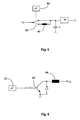
- the reed switch or the Functionality of the reed switch can be checked as follows. Immediately after when the rotary encoder 10 is switched on, the coil 44 or the coils by means of a bypass circuit, as is shown by way of example in FIG. 5, initially not energized. This is done via a microcontroller 50, which is a switch 52 operated, realized. Alternatively, the coils can be used instead of the bypass Switch 52 e.g. by one controlled by the microcontroller 50 Transistor 54 are switched, as shown in Fig. 6. This circuit is to be selected if, due to the high coil resistance, the function of the Coil 44 as filter choke must be dispensed with.
- the switching points of the reed switches are determined and with the absolute Angular position values of the shaft 16 compared.
- the coils 44 are energized and prevents switching of the reed switch according to the invention.
- they lying Switching points of the reed switches outside the tolerance range ⁇ P for example be provided to issue an error code.
Landscapes
- Physics & Mathematics (AREA)
- General Physics & Mathematics (AREA)
- Transmission And Conversion Of Sensor Element Output (AREA)
- Non-Deflectable Wheels, Steering Of Trailers, Or Other Steering (AREA)
- Selective Calling Equipment (AREA)
- Arrangements For Transmission Of Measured Signals (AREA)
- Rotary Switch, Piano Key Switch, And Lever Switch (AREA)
- Switches With Compound Operations (AREA)
Applications Claiming Priority (2)
| Application Number | Priority Date | Filing Date | Title |
|---|---|---|---|
| DE10308683 | 2003-02-28 | ||
| DE10308683A DE10308683B3 (de) | 2003-02-28 | 2003-02-28 | Multiturn-Drehgeber |
Publications (3)
| Publication Number | Publication Date |
|---|---|
| EP1452828A2 true EP1452828A2 (fr) | 2004-09-01 |
| EP1452828A3 EP1452828A3 (fr) | 2005-02-09 |
| EP1452828B1 EP1452828B1 (fr) | 2006-04-26 |
Family
ID=31984495
Family Applications (1)
| Application Number | Title | Priority Date | Filing Date |
|---|---|---|---|
| EP04002131A Expired - Lifetime EP1452828B1 (fr) | 2003-02-28 | 2004-02-02 | Codeur de rotation multitour |
Country Status (3)
| Country | Link |
|---|---|
| EP (1) | EP1452828B1 (fr) |
| AT (1) | ATE324568T1 (fr) |
| DE (2) | DE10308683B3 (fr) |
Families Citing this family (5)
| Publication number | Priority date | Publication date | Assignee | Title |
|---|---|---|---|---|
| US7256505B2 (en) | 2003-03-05 | 2007-08-14 | Microstrain, Inc. | Shaft mounted energy harvesting for wireless sensor operation and data transmission |
| EP1750095B1 (fr) | 2005-08-04 | 2016-11-23 | Getrag Ford Transmissions GmbH | Dispositif capteur avec au moins un élément capteur sensible aux champs magnétiques et méthode de détermination d'un signal de qualité pour un dispositif capteur |
| DE102005040150A1 (de) * | 2005-08-25 | 2007-03-01 | Leopold Kostal Gmbh & Co. Kg | Elektronischer Winkelsensor und Schaltungsanordnung |
| CN101832749B (zh) * | 2010-05-08 | 2012-02-08 | 锦州海伯伦汽车电子有限公司 | 霍尔式单路信号输出的防错位移传感器 |
| CN116222625B (zh) * | 2023-02-09 | 2023-09-12 | 哈尔滨理工大学 | 一种多并列无磁钢的多圈编码器装置及其计数方法 |
Family Cites Families (7)
| Publication number | Priority date | Publication date | Assignee | Title |
|---|---|---|---|---|
| IT1240133B (it) * | 1990-03-16 | 1993-11-27 | Prima Electronics S.P.A. | Dispositivo trasduttore di posizione |
| DE4011949A1 (de) * | 1990-04-13 | 1991-10-17 | Elektrotechnisches Spezialunte | Magnettauchsonde |
| DE4229610A1 (de) * | 1991-11-30 | 1993-06-03 | Irion & Vosseler | Drehgeber mit absolutwert-positionserfassung |
| DE19750474C2 (de) * | 1997-11-14 | 2000-08-10 | Stegmann Max Antriebstech | Drehgeber |
| DE19902736C2 (de) * | 1999-01-19 | 2001-07-19 | Huebner Elmasch Ag | Elektronischer Umdrehungszähler |
| DE10001676C1 (de) * | 2000-01-12 | 2001-08-02 | Huebner Elmasch Ag | Elektronischer Umdrehungszähler |
| DE10060574A1 (de) * | 2000-12-06 | 2002-06-13 | Heidenhain Gmbh Dr Johannes | Multiturn-Codedrehgeber |
-
2003
- 2003-02-28 DE DE10308683A patent/DE10308683B3/de not_active Expired - Fee Related
-
2004
- 2004-02-02 AT AT04002131T patent/ATE324568T1/de not_active IP Right Cessation
- 2004-02-02 EP EP04002131A patent/EP1452828B1/fr not_active Expired - Lifetime
- 2004-02-02 DE DE502004000450T patent/DE502004000450D1/de not_active Expired - Fee Related
Also Published As
| Publication number | Publication date |
|---|---|
| EP1452828A3 (fr) | 2005-02-09 |
| DE502004000450D1 (de) | 2006-06-01 |
| EP1452828B1 (fr) | 2006-04-26 |
| DE10308683B3 (de) | 2004-04-08 |
| ATE324568T1 (de) | 2006-05-15 |
Similar Documents
| Publication | Publication Date | Title |
|---|---|---|
| EP1364186B1 (fr) | Codeur rotatif | |
| EP2113742B1 (fr) | Dispositif de mesure doté d'un balayage à deux canaux | |
| DE10238640B4 (de) | Multiturn-Winkelmessgerät | |
| EP2105713B1 (fr) | Appareil de mesure de position et son procédé de fonctionnement | |
| EP1607720A2 (fr) | Capteur d'angle de braquage | |
| EP3936828B1 (fr) | Système de capteur pour un entraînement | |
| EP1662232A1 (fr) | Capteur de position linéaire | |
| DE102009029431A1 (de) | Multiturn-Drehgeber | |
| EP0157916B1 (fr) | Capteur analogue de distance | |
| DE102006008157A1 (de) | Magnetischer Sensor | |
| DE4229610A1 (de) | Drehgeber mit absolutwert-positionserfassung | |
| DE10310970B4 (de) | Vorrichtung zur Messung der Position, des Weges oder des Drehwinkels eines Objektes | |
| EP1260787A1 (fr) | Capteur d'angle utilisant des éléments de mesure magnétorésistifs | |
| EP2309232B1 (fr) | Indicateur de position doté d'une détermination de position à rotation multiple | |
| DE10308683B3 (de) | Multiturn-Drehgeber | |
| EP0550794A2 (fr) | Codeur de rotation avec détection de valeur absolue de position | |
| DE102008054973A1 (de) | Umdrehungszähler und Verfahren zum Feststellen der Umdrehungszahl einer Welle | |
| DE202008018076U1 (de) | Drehwinkelbestimmungsvorrichtung, insbesondere für die Lenkungswelle eines Kraftfahrzeuges | |
| DE10157565B4 (de) | Drehschalteinheit mit zusätzlicher Schaltfunktion | |
| DE3243956A1 (de) | Positionsgeber zur lagebestimmung linear verfahrbarer maschinenteile | |
| DE10354469B4 (de) | Vorrichtung zum Messen des Drehwinkels eines Drehkörpers | |
| DE102007043480A1 (de) | Anordnung zur Erfassung eines Drehwinkels | |
| DE102005061347A1 (de) | Anordnung zur Messung des absoluten Drehwinkels einer Welle | |
| DE10360016B3 (de) | Bedienvorrichtung mit digitalen Hallsensoren | |
| EP2469239A1 (fr) | Dispositif de mesure d'angle multi-tours |
Legal Events
| Date | Code | Title | Description |
|---|---|---|---|
| PUAI | Public reference made under article 153(3) epc to a published international application that has entered the european phase |
Free format text: ORIGINAL CODE: 0009012 |
|
| AK | Designated contracting states |
Kind code of ref document: A2 Designated state(s): AT BE BG CH CY CZ DE DK EE ES FI FR GB GR HU IE IT LI LU MC NL PT RO SE SI SK TR |
|
| AX | Request for extension of the european patent |
Extension state: AL LT LV MK |
|
| RAP1 | Party data changed (applicant data changed or rights of an application transferred) |
Owner name: SICK STEGMANN GMBH |
|
| PUAL | Search report despatched |
Free format text: ORIGINAL CODE: 0009013 |
|
| AK | Designated contracting states |
Kind code of ref document: A3 Designated state(s): AT BE BG CH CY CZ DE DK EE ES FI FR GB GR HU IE IT LI LU MC NL PT RO SE SI SK TR |
|
| AX | Request for extension of the european patent |
Extension state: AL LT LV MK |
|
| RIC1 | Information provided on ipc code assigned before grant |
Ipc: 7G 01D 5/249 B Ipc: 7G 01D 5/245 B Ipc: 7G 01D 5/251 B Ipc: 7G 01B 7/30 A |
|
| 17P | Request for examination filed |
Effective date: 20050311 |
|
| GRAP | Despatch of communication of intention to grant a patent |
Free format text: ORIGINAL CODE: EPIDOSNIGR1 |
|
| AKX | Designation fees paid |
Designated state(s): AT BE BG CH CY CZ DE DK EE ES FI FR GB GR HU IE IT LI LU MC NL PT RO SE SI SK TR |
|
| GRAS | Grant fee paid |
Free format text: ORIGINAL CODE: EPIDOSNIGR3 |
|
| GRAA | (expected) grant |
Free format text: ORIGINAL CODE: 0009210 |
|
| AK | Designated contracting states |
Kind code of ref document: B1 Designated state(s): AT BE BG CH CY CZ DE DK EE ES FI FR GB GR HU IE IT LI LU MC NL PT RO SE SI SK TR |
|
| PG25 | Lapsed in a contracting state [announced via postgrant information from national office to epo] |
Ref country code: CZ Free format text: LAPSE BECAUSE OF FAILURE TO SUBMIT A TRANSLATION OF THE DESCRIPTION OR TO PAY THE FEE WITHIN THE PRESCRIBED TIME-LIMIT Effective date: 20060426 Ref country code: FI Free format text: LAPSE BECAUSE OF FAILURE TO SUBMIT A TRANSLATION OF THE DESCRIPTION OR TO PAY THE FEE WITHIN THE PRESCRIBED TIME-LIMIT Effective date: 20060426 Ref country code: IE Free format text: LAPSE BECAUSE OF FAILURE TO SUBMIT A TRANSLATION OF THE DESCRIPTION OR TO PAY THE FEE WITHIN THE PRESCRIBED TIME-LIMIT Effective date: 20060426 Ref country code: NL Free format text: LAPSE BECAUSE OF FAILURE TO SUBMIT A TRANSLATION OF THE DESCRIPTION OR TO PAY THE FEE WITHIN THE PRESCRIBED TIME-LIMIT Effective date: 20060426 Ref country code: RO Free format text: LAPSE BECAUSE OF FAILURE TO SUBMIT A TRANSLATION OF THE DESCRIPTION OR TO PAY THE FEE WITHIN THE PRESCRIBED TIME-LIMIT Effective date: 20060426 Ref country code: SI Free format text: LAPSE BECAUSE OF FAILURE TO SUBMIT A TRANSLATION OF THE DESCRIPTION OR TO PAY THE FEE WITHIN THE PRESCRIBED TIME-LIMIT Effective date: 20060426 Ref country code: SK Free format text: LAPSE BECAUSE OF FAILURE TO SUBMIT A TRANSLATION OF THE DESCRIPTION OR TO PAY THE FEE WITHIN THE PRESCRIBED TIME-LIMIT Effective date: 20060426 |
|
| REG | Reference to a national code |
Ref country code: GB Ref legal event code: FG4D Free format text: NOT ENGLISH |
|
| GBT | Gb: translation of ep patent filed (gb section 77(6)(a)/1977) |
Effective date: 20060426 |
|
| REG | Reference to a national code |
Ref country code: IE Ref legal event code: FG4D Free format text: LANGUAGE OF EP DOCUMENT: GERMAN |
|
| REF | Corresponds to: |
Ref document number: 502004000450 Country of ref document: DE Date of ref document: 20060601 Kind code of ref document: P |
|
| PG25 | Lapsed in a contracting state [announced via postgrant information from national office to epo] |
Ref country code: DK Free format text: LAPSE BECAUSE OF FAILURE TO SUBMIT A TRANSLATION OF THE DESCRIPTION OR TO PAY THE FEE WITHIN THE PRESCRIBED TIME-LIMIT Effective date: 20060726 Ref country code: SE Free format text: LAPSE BECAUSE OF FAILURE TO SUBMIT A TRANSLATION OF THE DESCRIPTION OR TO PAY THE FEE WITHIN THE PRESCRIBED TIME-LIMIT Effective date: 20060726 |
|
| PG25 | Lapsed in a contracting state [announced via postgrant information from national office to epo] |
Ref country code: ES Free format text: LAPSE BECAUSE OF FAILURE TO SUBMIT A TRANSLATION OF THE DESCRIPTION OR TO PAY THE FEE WITHIN THE PRESCRIBED TIME-LIMIT Effective date: 20060806 |
|
| PG25 | Lapsed in a contracting state [announced via postgrant information from national office to epo] |
Ref country code: PT Free format text: LAPSE BECAUSE OF FAILURE TO SUBMIT A TRANSLATION OF THE DESCRIPTION OR TO PAY THE FEE WITHIN THE PRESCRIBED TIME-LIMIT Effective date: 20060926 |
|
| NLV1 | Nl: lapsed or annulled due to failure to fulfill the requirements of art. 29p and 29m of the patents act | ||
| REG | Reference to a national code |
Ref country code: IE Ref legal event code: FD4D |
|
| ET | Fr: translation filed | ||
| PG25 | Lapsed in a contracting state [announced via postgrant information from national office to epo] |
Ref country code: MC Free format text: LAPSE BECAUSE OF NON-PAYMENT OF DUE FEES Effective date: 20070228 |
|
| PLAX | Notice of opposition and request to file observation + time limit sent |
Free format text: ORIGINAL CODE: EPIDOSNOBS2 |
|
| PLBI | Opposition filed |
Free format text: ORIGINAL CODE: 0009260 |
|
| PLBB | Reply of patent proprietor to notice(s) of opposition received |
Free format text: ORIGINAL CODE: EPIDOSNOBS3 |
|
| 26 | Opposition filed |
Opponent name: IVO GMBH & CO. KG Effective date: 20070126 |
|
| PLAB | Opposition data, opponent's data or that of the opponent's representative modified |
Free format text: ORIGINAL CODE: 0009299OPPO |
|
| R26 | Opposition filed (corrected) |
Opponent name: BAUMER IVO GMBH & CO. KG Effective date: 20070126 |
|
| REG | Reference to a national code |
Ref country code: FR Ref legal event code: ST Effective date: 20071030 |
|
| BERE | Be: lapsed |
Owner name: SICK STEGMANN G.M.B.H. Effective date: 20070228 |
|
| PG25 | Lapsed in a contracting state [announced via postgrant information from national office to epo] |
Ref country code: BE Free format text: LAPSE BECAUSE OF NON-PAYMENT OF DUE FEES Effective date: 20070228 |
|
| PG25 | Lapsed in a contracting state [announced via postgrant information from national office to epo] |
Ref country code: DE Free format text: LAPSE BECAUSE OF NON-PAYMENT OF DUE FEES Effective date: 20070901 |
|
| PG25 | Lapsed in a contracting state [announced via postgrant information from national office to epo] |
Ref country code: GR Free format text: LAPSE BECAUSE OF FAILURE TO SUBMIT A TRANSLATION OF THE DESCRIPTION OR TO PAY THE FEE WITHIN THE PRESCRIBED TIME-LIMIT Effective date: 20060727 Ref country code: FR Free format text: LAPSE BECAUSE OF NON-PAYMENT OF DUE FEES Effective date: 20070228 |
|
| PG25 | Lapsed in a contracting state [announced via postgrant information from national office to epo] |
Ref country code: BG Free format text: LAPSE BECAUSE OF FAILURE TO SUBMIT A TRANSLATION OF THE DESCRIPTION OR TO PAY THE FEE WITHIN THE PRESCRIBED TIME-LIMIT Effective date: 20060726 Ref country code: AT Free format text: LAPSE BECAUSE OF NON-PAYMENT OF DUE FEES Effective date: 20070202 |
|
| PG25 | Lapsed in a contracting state [announced via postgrant information from national office to epo] |
Ref country code: EE Free format text: LAPSE BECAUSE OF FAILURE TO SUBMIT A TRANSLATION OF THE DESCRIPTION OR TO PAY THE FEE WITHIN THE PRESCRIBED TIME-LIMIT Effective date: 20060426 |
|
| REG | Reference to a national code |
Ref country code: CH Ref legal event code: PL |
|
| GBPC | Gb: european patent ceased through non-payment of renewal fee |
Effective date: 20080202 |
|
| PG25 | Lapsed in a contracting state [announced via postgrant information from national office to epo] |
Ref country code: CH Free format text: LAPSE BECAUSE OF NON-PAYMENT OF DUE FEES Effective date: 20080229 Ref country code: LI Free format text: LAPSE BECAUSE OF NON-PAYMENT OF DUE FEES Effective date: 20080229 |
|
| PG25 | Lapsed in a contracting state [announced via postgrant information from national office to epo] |
Ref country code: GB Free format text: LAPSE BECAUSE OF NON-PAYMENT OF DUE FEES Effective date: 20080202 |
|
| PG25 | Lapsed in a contracting state [announced via postgrant information from national office to epo] |
Ref country code: LU Free format text: LAPSE BECAUSE OF NON-PAYMENT OF DUE FEES Effective date: 20070202 Ref country code: CY Free format text: LAPSE BECAUSE OF FAILURE TO SUBMIT A TRANSLATION OF THE DESCRIPTION OR TO PAY THE FEE WITHIN THE PRESCRIBED TIME-LIMIT Effective date: 20060426 |
|
| PG25 | Lapsed in a contracting state [announced via postgrant information from national office to epo] |
Ref country code: HU Free format text: LAPSE BECAUSE OF FAILURE TO SUBMIT A TRANSLATION OF THE DESCRIPTION OR TO PAY THE FEE WITHIN THE PRESCRIBED TIME-LIMIT Effective date: 20061027 Ref country code: TR Free format text: LAPSE BECAUSE OF FAILURE TO SUBMIT A TRANSLATION OF THE DESCRIPTION OR TO PAY THE FEE WITHIN THE PRESCRIBED TIME-LIMIT Effective date: 20060426 |
|
| PLBD | Termination of opposition procedure: decision despatched |
Free format text: ORIGINAL CODE: EPIDOSNOPC1 |
|
| PLBM | Termination of opposition procedure: date of legal effect published |
Free format text: ORIGINAL CODE: 0009276 |
|
| STAA | Information on the status of an ep patent application or granted ep patent |
Free format text: STATUS: OPPOSITION PROCEDURE CLOSED |
|
| PG25 | Lapsed in a contracting state [announced via postgrant information from national office to epo] |
Ref country code: IT Free format text: LAPSE BECAUSE OF NON-PAYMENT OF DUE FEES Effective date: 20080202 |
|
| PGFP | Annual fee paid to national office [announced via postgrant information from national office to epo] |
Ref country code: IT Payment date: 20070228 Year of fee payment: 4 |
|
| 27C | Opposition proceedings terminated |
Effective date: 20111102 |