EP1452763A2 - Poulie de découplage et moteur à combustion interne équipé d'une telle poulie - Google Patents
Poulie de découplage et moteur à combustion interne équipé d'une telle poulie Download PDFInfo
- Publication number
- EP1452763A2 EP1452763A2 EP04290540A EP04290540A EP1452763A2 EP 1452763 A2 EP1452763 A2 EP 1452763A2 EP 04290540 A EP04290540 A EP 04290540A EP 04290540 A EP04290540 A EP 04290540A EP 1452763 A2 EP1452763 A2 EP 1452763A2
- Authority
- EP
- European Patent Office
- Prior art keywords
- pulley
- hub
- rim
- cavity
- crankshaft
- Prior art date
- Legal status (The legal status is an assumption and is not a legal conclusion. Google has not performed a legal analysis and makes no representation as to the accuracy of the status listed.)
- Granted
Links
Images

Classifications
-
- F—MECHANICAL ENGINEERING; LIGHTING; HEATING; WEAPONS; BLASTING
- F16—ENGINEERING ELEMENTS AND UNITS; GENERAL MEASURES FOR PRODUCING AND MAINTAINING EFFECTIVE FUNCTIONING OF MACHINES OR INSTALLATIONS; THERMAL INSULATION IN GENERAL
- F16F—SPRINGS; SHOCK-ABSORBERS; MEANS FOR DAMPING VIBRATION
- F16F15/00—Suppression of vibrations in systems; Means or arrangements for avoiding or reducing out-of-balance forces, e.g. due to motion
- F16F15/10—Suppression of vibrations in rotating systems by making use of members moving with the system
- F16F15/16—Suppression of vibrations in rotating systems by making use of members moving with the system using a fluid or pasty material
- F16F15/161—Suppression of vibrations in rotating systems by making use of members moving with the system using a fluid or pasty material characterised by the fluid damping devices, e.g. passages, orifices
-
- F—MECHANICAL ENGINEERING; LIGHTING; HEATING; WEAPONS; BLASTING
- F16—ENGINEERING ELEMENTS AND UNITS; GENERAL MEASURES FOR PRODUCING AND MAINTAINING EFFECTIVE FUNCTIONING OF MACHINES OR INSTALLATIONS; THERMAL INSULATION IN GENERAL
- F16D—COUPLINGS FOR TRANSMITTING ROTATION; CLUTCHES; BRAKES
- F16D35/00—Fluid clutches in which the clutching is predominantly obtained by fluid adhesion
-
- F—MECHANICAL ENGINEERING; LIGHTING; HEATING; WEAPONS; BLASTING
- F16—ENGINEERING ELEMENTS AND UNITS; GENERAL MEASURES FOR PRODUCING AND MAINTAINING EFFECTIVE FUNCTIONING OF MACHINES OR INSTALLATIONS; THERMAL INSULATION IN GENERAL
- F16D—COUPLINGS FOR TRANSMITTING ROTATION; CLUTCHES; BRAKES
- F16D7/00—Slip couplings, e.g. slipping on overload, for absorbing shock
- F16D7/02—Slip couplings, e.g. slipping on overload, for absorbing shock of the friction type
-
- F—MECHANICAL ENGINEERING; LIGHTING; HEATING; WEAPONS; BLASTING
- F16—ENGINEERING ELEMENTS AND UNITS; GENERAL MEASURES FOR PRODUCING AND MAINTAINING EFFECTIVE FUNCTIONING OF MACHINES OR INSTALLATIONS; THERMAL INSULATION IN GENERAL
- F16F—SPRINGS; SHOCK-ABSORBERS; MEANS FOR DAMPING VIBRATION
- F16F15/00—Suppression of vibrations in systems; Means or arrangements for avoiding or reducing out-of-balance forces, e.g. due to motion
- F16F15/10—Suppression of vibrations in rotating systems by making use of members moving with the system
- F16F15/12—Suppression of vibrations in rotating systems by making use of members moving with the system using elastic members or friction-damping members, e.g. between a rotating shaft and a gyratory mass mounted thereon
- F16F15/121—Suppression of vibrations in rotating systems by making use of members moving with the system using elastic members or friction-damping members, e.g. between a rotating shaft and a gyratory mass mounted thereon using springs as elastic members, e.g. metallic springs
- F16F15/124—Elastomeric springs
- F16F15/126—Elastomeric springs consisting of at least one annular element surrounding the axis of rotation
Definitions
- the present invention relates to a pulley of decoupling intended to transmit a torque between a tree around which the pulley and a transmission belt itself mounted around the pulley, said pulley comprising a hub and a rim arranged between them to delimit a cavity in which is mounted at least one element suitable for filtering the acyclisms of the rotating shaft.
- pulleys of this type which are fitted to motors with internal combustion and, in particular, those which are fitted at the crankshaft outlet of internal combustion engine and which are suitable to transmit the motor output torque to an accessory such as a pump by through a transmission belt.
- a major problem currently encountered in the training of accessories equipping heat engines is the difficulty of power transmission at the output of the crankshaft with different accessories by through the transmission belt.
- This difficulty comes essentially from the causes each engine to exhibit behavior more or less acyclic depending on the load and diet.
- a current solution is to place an element decoupling rubber inside the driving pulley, i.e. the pulley mounted to the crankshaft outlet, between the outer rim and the hub. This solution allows to filter part of the motor acyclisms in the most of the operating cycles of this one.
- decoupling through a rubber element necessarily leads to resonance modes limiting its effectiveness according to the engine speeds. This is all more proven for powertrains fitted with a double shock-absorbing flywheel. It is then necessary to place a freewheel on the alternator to avoid resonances between the double shock-absorbing flywheel and the pulley decoupling accessory. In the absence of this freewheel, belt snaps may be heard by the driver of the vehicle automobile when the engine is started. Such clicks can be really harmful.
- the object of the invention is then to limit more importantly the negative effects dynamic tensions generated by accessory drive devices for internal combustion engine or those of the engine.
- the invention relates to a decoupling pulley, intended to transmit the couple between a tree around which is climbed the pulley and a drive belt itself mounted around the pulley, said pulley comprising a hub and a rim arranged between them to delimit a cavity in which is mounted at least one element suitable for filtering the cyclisms of the rotating shaft, characterized in that the hub and the rim are further arranged between them to authorize a limited rotation between hub and rim when cyclisms of the rotating shaft.
- the arrangement made between the rim and the hub is such that the rim is mounted coaxial with the hub, the cavity is sealed by at least one dynamic sealing element and is completely filled with a fluid incompressible and each of the respective faces rim and hub in contact with the fluid is provided with a series of blades.
- the pale are straight and standard effect.
- the pale are oriented freewheeling effect.
- the rim presents in section axial the general shape of a triple U whose outer branches make up the area of contact with the transmission belt and inner branches make up the walls of its central bore.
- the rim is the shaped outer rim suitable for training the transmission belt.
- the pulley includes an Avt stage placed inside of the hub bore.
- the Avt stage is made up an element made of elastomeric material such that the rubber in contact with the bore inside the hub and a rigid hub such than a crankshaft hub suitable for mounting around the tree.
- the rubber is glued to the pulley hub.
- it includes a stop axial mounted in a peripheral groove of the hub pulley adapted to maintain the arrangement of the hub with respect to the rim.
- the rim and / or the hub are drilled in two diametrically opposite and closed holes.
- the obturation of the two holes is made by type plugs screw / cap.
- the first technical effect thus achieved by the pulley according to the invention is to reduce the dynamic tensions whatever the operating phases of the rotating shaft on which the pulley and (s) are mounted accessory (s) driven by the belt transmission mounted around the pulley.
- the rotating shaft is the crankshaft of a combustion engine
- the variations in engine or accessory torque are thus smoothed by a temporary sliding of the rim relative to the hub or, in other words, by a slip of the rim in relation to the hub.
- the pulley according to the invention is arranged in such a way that a rotation complete between the outer rim and the hub is always possible once the pulley assembled but not mounted around the tree.
- the fluid circulates between the two sets of pale opposite exerting an effort on each series of blades without there being a rotation of the hub by compared to the rim.
- the invention also relates to a motor with internal combustion including a crankshaft and a pulley as described above, in which the pulley is fitted around the output end of the crankshaft.
- a preferred mounting method is such that the pulley is fitted around a shoulder made at the end of the crankshaft and is kept fixed by a washer itself held by a screw screwed at the end of crankshaft.
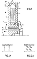
- Figure 1 a pulley according to the invention 1 fitted on a shoulder 2 made at the end of a crankshaft 3 of a internal combustion engine and maintained in place by a screw 4 screwed at the end of crankshaft and a washer 41.
- This pulley 1 consists of a hub 11 and an outer rim 12 provided at its outer periphery of a set of V 13 suitable for driving a transmission chain not shown, said V-belt.
- the arrangement between the hub 11 and the rim exterior 12 is such that they delimit a cavity 14 sealed by means of two dynamic sealing means 15, that is to say whose sealing function remains effective when the crankshaft is rotating.
- These dynamic sealing means can be joints 15a, 15b.
- the cavity 14 is completely filled with a incompressible fluid 141 of viscosity defined and present on each of the faces in look respectively at the hub 11 and the rim 12, a pale 16 of parallelepiped section as shown in Figure 1a. In this mode illustrated, all pale 16 are identical to each other. The pale 16 are here straight with standard effect.
- the pulley 1 comprises also an Avt 17 stage consisting of a hub crankshaft 18 on which an element is stuck cylindrical rubber 19 itself being directly glued to the hub 11.
- Maintaining the outer rim 12 on the pulley 11 is ensured by a circlip 20 mounted in a groove 110 made on the periphery of the hub.
- the hub 11 and the rim 12 each have an axial section in shape triple U, the central part 110 of the hub 11 being such that it allows the fitting of the outer rim 12 around the hub 11 by its inner bore 180, the seal 15a allowing sealing between the two elements 11 and 12.
- the wall exterior 121 is sized to be flush in the plane formed by the plane of the hub, the seal 15b mounted in the outer wall 111 of the hub 11 for sealing between the two elements 11 and 12.
- the elastomer 19 is bonded to the crankshaft hub 18 then we just stick the set 18, 19 glued inside the bore of the hub 18 of the pulley.
- the pulley according to the invention 1 is then placed so that the hole 21 connected to the vacuum source 25 is at the highest point.
- the fluid reservoir then delivers incompressible fluid 141 in the cavity 14 by hole 21, the vacuum being produced by the source vacuum 25 through the other hole 21.
- Pulley 1 is then assembled and ready to be mounted directly at the end of the shaft, as than a crankshaft.
- FIG. 2a Another embodiment of the invention is shown in Figure 2a in which we see two blades oriented so-called freewheeling effect, that is to say . .. This means that when the motor resdescend in regime, it does not brake the accessories as strongly as it must train them.
- the pulley slides freewheeling and that the accessories remain at speed for a few seconds before the engine goes back up.
- limiting the rim rotation with respect to the hub during acyclisms of the motor can take different values, depending on the intended application.
- the number of pale implanted respectively on the outer rim and the hub may be larger than that described above, depending for example on the power of the tree to transmit.
- the inclination of the blades can present a larger angle.
- the spacing, the geometry of the blades can also be different depending on the intended application.
- the profile of the periphery of the rim can take different forms for adapt to different types of belt (ex: herringbone belt, V-belt, ...)
- a fluid with suitable viscosity allows less smoothing of motor torque acyclisms.
- the invention advantageously allows remove the freewheel from the alternator to engine applications in which it there is a double damping flywheel.
Landscapes
- Engineering & Computer Science (AREA)
- General Engineering & Computer Science (AREA)
- Mechanical Engineering (AREA)
- Physics & Mathematics (AREA)
- Acoustics & Sound (AREA)
- Aviation & Aerospace Engineering (AREA)
- Pulleys (AREA)
- Devices For Conveying Motion By Means Of Endless Flexible Members (AREA)
- External Artificial Organs (AREA)
- Medicines Containing Material From Animals Or Micro-Organisms (AREA)
Abstract
Description
- Figure 1: une vue en coupe axiale d'une poulie selon l'invention montée en bout de vilebrequin d'un moteur à combustion interne ;
- Figure 1a : une vue en coupe transversale d'une partie de la poulie selon la figure 1 dans laquelle les pâles de la poulie sont dites « droites » ;
- Figure 2a : une vue en coupe transversale d'une partie d'une autre poulie conforme à l'invention dans laquelle les pâles de la poulie sont dites orientées ;
- Figure 3a : une vue éclatée de la poulie selon l'invention 1 ;
- Figure 3b : une vue schématique de la poulie selon l'invention 1 et du dispositif de remplissage associé.
Claims (18)
- Poulie de découplage (1), destinée à transmettre un couple entre un arbre autour duquel est montée la poulie et une courroie de transmission elle-même montée autour de la poulie, ladite poulie comprenant un moyeu (11) et une jante (12) agencés entre eux pour délimiter une cavité (14) dans laquelle est montée au moins un élément (141,16) adapté pour filtrer les acyclismes de l'arbre en rotation, dans laquelle le moyeu et la jante sont agencés entre eux pour autoriser une rotation limitée de l'un par rapport à l'autre lors des acyclismes de l'arbre en rotation, caractérisée en ce que l'agencement réalisé entre la jante et le moyeu est tel que la jante est montée coaxiale au moyeu, la cavité est étanchéifiée par au moins un élément d'étanchéité dynamique (15a,15b) et est remplie complètement d'un fluide incompressible (141) et chacune des faces respectives de la jante et du moyeu en contact avec le fluide est pourvue d'une série de pâles (16).
- Poulie selon la revendication 1, caractérisée en ce que les pâles sont droites et à effet dit standard.
- Poulie selon la revendication 1, caractérisée en ce que les pâles sont orientées à effet dit roue libre.
- Poulie selon l'une quelconque des revendications précédentes, caractérisée en ce que la jante présente en coupe axiale la forme générale d'un triple U dont les branches extérieures constituent la zone de contact avec la courroie de transmission et les branches intérieures constituent les parois de son alésage central.
- Poulie selon l'une quelconque des revendications précédentes, caractérisée en ce que, la jante est la jante extérieure de forme adaptée pour entraíner la courroie de transmission.
- Poulie selon l'une quelconque des revendications précédentes, caractérisée en ce que, elle comprend un étage Avt (17) placé à l'intérieur de l'alésage du moyeu.
- Poulie selon l'une quelconque des revendications précédentes, caractérisée en ce que l'étage Avt (17) est constitué d'un élément (19) réalisé en matériau élastomère tel que le caoutchouc en contact avec l'alésage intérieur du moyeu et d'un moyeu rigide (18) tel qu'un moyeu vilebrequin adapté pour être monté autour de l'arbre.
- Poulie selon la revendication 7, caractérisée en ce que le caoutchouc est collé au moyeu de la poulie.
- Poulie selon l'une quelconque des revendications précédentes, caractérisée en ce qu'elle comprend un arrêt axial (21) monté dans une gorge périphérique (110) du moyeu de la poulie adapté pour maintenir l'agencement du moyeu par rapport à la jante.
- Poulie selon l'une quelconque des revendications précédentes, caractérisée en ce que la jante et/ou le moyeu sont percés de deux trous (21) diamétralement opposés et obturés.
- Poulie selon la revendication 10, caractérisée en ce que l'obturation des deux trous est réalisée par des bouchons de type vis/bouchon (26).
- Procédé d'assemblage de la poulie selon l'une quelconque des revendications précédentes, caractérisé en ce que on réalise les étapes suivantes :a/mise en place dudit au moins un élément d'étanchéité dynamique sur la jante ou le moyeu ;b/emmanchement de la jante autour du moyeu ;c/remplissage complet de la cavité par le fluide incompressible.
- Procédé selon la revendication 12, caractérisé en ce qu'on met en place l'arrêt axial dans la gorge périphérique du moyeu de la poulie pour maintenir l'agencement du moyeu par rapport à la jante.
- Procédé d'assemblage de la poulie selon la revendication 10 ou 11, selon lequel on effectue au préalable les étapes a/ et b/ du procédé selon la revendication 12 ou 13 caractérisé en ce que on effectue le remplissage complet de la cavité de la manière suivante :c'/emmanchement d'une extrémité d'un premier tuyau à l'un des trous dont l'autre extrémité est reliée à un réservoir du fluide incompressible ;c''/emmanchement d'une extrémité d'un deuxième tuyau à l'autre extrémité à l'autre des trous dont l'autre extrémité est reliée à une source de vide ;c"'/mise sous vide du trou relié à la source de vide ;c' ' ' '/remplissage complet de la cavité par le fluide incompressible par le trou relié au réservoir de fluide.
- Procédé selon l'une quelconque des revendications 12 à 14, caractérisé en ce qu'avant d'effectuer le remplissage complet de la cavité 14 on place la poulie de telle sorte que le trou relié au réservoir de fluide soit au point le plus haut.
- Procédé d'assemblage d'une poulie selon l'une quelconque des revendications 12 à 15, caractérisé en ce qu'après avoir effectué le remplissage de la cavité, on place la poulie à l'horizontal puis on met en place les vis bouchons.
- Moteur à combustion interne comprenant un vilebrequin et une poulie selon l'une quelconque des revendications 1 à 11, caractérisé en ce que la poulie est emmanchée autour de l'extrémité de sortie du vilebrequin (3).
- Moteur selon la revendication 17, caractérisé en ce que la poulie est emmanchée autour d'un épaulement réalisé à l'extrémité de vilebrequin et est maintenue fixée par une rondelle (41) elle-même maintenue par une vis (4) vissée en bout de vilebrequin.
Applications Claiming Priority (2)
| Application Number | Priority Date | Filing Date | Title |
|---|---|---|---|
| FR0302479 | 2003-02-28 | ||
| FR0302479A FR2851805B1 (fr) | 2003-02-28 | 2003-02-28 | Poulie de decouplage et moteur a combustion interne equipe d'une telle poulie |
Publications (3)
| Publication Number | Publication Date |
|---|---|
| EP1452763A2 true EP1452763A2 (fr) | 2004-09-01 |
| EP1452763A3 EP1452763A3 (fr) | 2005-11-16 |
| EP1452763B1 EP1452763B1 (fr) | 2007-10-10 |
Family
ID=32749752
Family Applications (1)
| Application Number | Title | Priority Date | Filing Date |
|---|---|---|---|
| EP04290540A Expired - Lifetime EP1452763B1 (fr) | 2003-02-28 | 2004-02-27 | Poulie de découplage |
Country Status (5)
| Country | Link |
|---|---|
| EP (1) | EP1452763B1 (fr) |
| AT (1) | ATE375468T1 (fr) |
| DE (1) | DE602004009350T2 (fr) |
| ES (1) | ES2293177T3 (fr) |
| FR (1) | FR2851805B1 (fr) |
Family Cites Families (6)
| Publication number | Priority date | Publication date | Assignee | Title |
|---|---|---|---|---|
| DE1980470U (de) * | 1967-10-12 | 1968-03-07 | Stromag Maschf | Sicherheitskupplung. |
| DE2425797A1 (de) * | 1974-05-28 | 1975-12-04 | Wolfgang Dabisch | Vorrichtung zur uebertragung eines variablen drehmomentes |
| SE8107037L (sv) * | 1981-04-08 | 1982-10-09 | Wallace Murray Corp | Anordning vid remskivedrift |
| JPH02146321A (ja) * | 1988-11-29 | 1990-06-05 | Tochigi Fuji Ind Co Ltd | ビスカスカップリング |
| JPH02203023A (ja) * | 1989-01-31 | 1990-08-13 | Tochigi Fuji Ind Co Ltd | 粘性流体クラッチ |
| DE4328596C2 (de) * | 1993-08-25 | 1997-12-11 | Metzeler Gimetall Ag | Anordnung zur Dämpfung von Schwingungen an Kurbelwellen |
-
2003
- 2003-02-28 FR FR0302479A patent/FR2851805B1/fr not_active Expired - Fee Related
-
2004
- 2004-02-27 AT AT04290540T patent/ATE375468T1/de not_active IP Right Cessation
- 2004-02-27 EP EP04290540A patent/EP1452763B1/fr not_active Expired - Lifetime
- 2004-02-27 DE DE602004009350T patent/DE602004009350T2/de not_active Expired - Lifetime
- 2004-02-27 ES ES04290540T patent/ES2293177T3/es not_active Expired - Lifetime
Also Published As
| Publication number | Publication date |
|---|---|
| EP1452763A3 (fr) | 2005-11-16 |
| DE602004009350D1 (de) | 2007-11-22 |
| FR2851805A1 (fr) | 2004-09-03 |
| FR2851805B1 (fr) | 2006-02-24 |
| ES2293177T3 (es) | 2008-03-16 |
| DE602004009350T2 (de) | 2008-07-10 |
| ATE375468T1 (de) | 2007-10-15 |
| EP1452763B1 (fr) | 2007-10-10 |
Similar Documents
| Publication | Publication Date | Title |
|---|---|---|
| EP0924425B1 (fr) | Démarreur de véhicule automobile comportant un lanceur perfectionné. | |
| EP1089021B1 (fr) | Volant de moteur thermique comprenant une couronne dentée de démarrage | |
| FR2907516A1 (fr) | Dispositif de transmission de couple de demarrage de moteur | |
| FR2867248A1 (fr) | Transmission variable en continu a courroie destinee a un vehicule | |
| FR2799246A1 (fr) | Installation d'embrayage multiple avec au moins un dispostif de palier | |
| EP3244083B1 (fr) | Poulie de decouplage a embrayage deporte | |
| FR2535302A1 (fr) | Dispositif d'entrainement pour tambour a cable d'enroulement | |
| WO2016177549A1 (fr) | Ensemble electromecanique comportant une machine electrique couplee a un reducteur | |
| FR3116578A1 (fr) | Dispositif d’entraînement électrique d’un essieu d’un véhicule | |
| FR3050505A1 (fr) | Procede pour determiner l'usure de la courroie d'un entrainement par courroie | |
| WO2011015719A2 (fr) | Tendeur hydraulique pilotable | |
| EP3922814A1 (fr) | Système de lubrification pour fournir un fluide aux cannelures d'un arbre d'entrainement | |
| FR2657930A1 (fr) | Embrayage a deux disques. | |
| EP3234359B1 (fr) | Appareil hydraulique a pistons radiaux comprenant au moins un roulement a billes | |
| EP1452763B1 (fr) | Poulie de découplage | |
| FR2734036A1 (fr) | Dispositif de volant moteur comprenant un element d'etancheite | |
| EP0921307B1 (fr) | Démarreur de véhicule automobile à réducteur à engrenages comportant un dispositif limiteur d'à-coups | |
| FR2744187A1 (fr) | Dispositif de commande pour un accouplement | |
| FR2677947A1 (fr) | Ensemble d'equilibrage ameliore. | |
| EP1669594B1 (fr) | Dispositif de démarrage d'un moteur thermique | |
| FR2736122A1 (fr) | Dispositif a volant d'inertie | |
| EP1609965B1 (fr) | Agencement avec liaison par entrainement d'un organe auxiliaire et boîte d'entraînement pour un entraînement d'au moins un organe auxiliaire | |
| FR2885393A1 (fr) | Demarreur de moteur concu pour presenter une durabilite amelioree | |
| FR2905996A1 (fr) | Dispositif de montage d'un pignon de distribution et d'une poulie accessoire sur un nez de vilebrequin. | |
| FR2717545A1 (fr) | Procédé et dispositif pour une transmission de puissance du type à changement de vitesse continument variable, avec fonction d'embrayage. |
Legal Events
| Date | Code | Title | Description |
|---|---|---|---|
| PUAI | Public reference made under article 153(3) epc to a published international application that has entered the european phase |
Free format text: ORIGINAL CODE: 0009012 |
|
| AK | Designated contracting states |
Kind code of ref document: A2 Designated state(s): AT BE BG CH CY CZ DE DK EE ES FI FR GB GR HU IE IT LI LU MC NL PT RO SE SI SK TR |
|
| AX | Request for extension of the european patent |
Extension state: AL HR LT LV MK |
|
| PUAL | Search report despatched |
Free format text: ORIGINAL CODE: 0009013 |
|
| AK | Designated contracting states |
Kind code of ref document: A3 Designated state(s): AT BE BG CH CY CZ DE DK EE ES FI FR GB GR HU IE IT LI LU MC NL PT RO SE SI SK TR |
|
| AX | Request for extension of the european patent |
Extension state: AL LT LV MK |
|
| RIC1 | Information provided on ipc code assigned before grant |
Ipc: 7F 16F 15/16 A |
|
| 17P | Request for examination filed |
Effective date: 20060512 |
|
| AKX | Designation fees paid |
Designated state(s): AT BE BG CH CY CZ DE DK EE ES FI FR GB GR HU IE IT LI LU MC NL PT RO SE SI SK TR |
|
| 17Q | First examination report despatched |
Effective date: 20060728 |
|
| GRAP | Despatch of communication of intention to grant a patent |
Free format text: ORIGINAL CODE: EPIDOSNIGR1 |
|
| RTI1 | Title (correction) |
Free format text: DECOUPLING PULLEY |
|
| GRAS | Grant fee paid |
Free format text: ORIGINAL CODE: EPIDOSNIGR3 |
|
| GRAA | (expected) grant |
Free format text: ORIGINAL CODE: 0009210 |
|
| AK | Designated contracting states |
Kind code of ref document: B1 Designated state(s): AT BE BG CH CY CZ DE DK EE ES FI FR GB GR HU IE IT LI LU MC NL PT RO SE SI SK TR |
|
| REG | Reference to a national code |
Ref country code: GB Ref legal event code: FG4D Free format text: NOT ENGLISH |
|
| REG | Reference to a national code |
Ref country code: CH Ref legal event code: EP |
|
| REG | Reference to a national code |
Ref country code: IE Ref legal event code: FG4D Free format text: LANGUAGE OF EP DOCUMENT: FRENCH |
|
| REF | Corresponds to: |
Ref document number: 602004009350 Country of ref document: DE Date of ref document: 20071122 Kind code of ref document: P |
|
| GBT | Gb: translation of ep patent filed (gb section 77(6)(a)/1977) |
Effective date: 20071206 |
|
| REG | Reference to a national code |
Ref country code: ES Ref legal event code: FG2A Ref document number: 2293177 Country of ref document: ES Kind code of ref document: T3 |
|
| NLV1 | Nl: lapsed or annulled due to failure to fulfill the requirements of art. 29p and 29m of the patents act | ||
| PG25 | Lapsed in a contracting state [announced via postgrant information from national office to epo] |
Ref country code: NL Free format text: LAPSE BECAUSE OF FAILURE TO SUBMIT A TRANSLATION OF THE DESCRIPTION OR TO PAY THE FEE WITHIN THE PRESCRIBED TIME-LIMIT Effective date: 20071010 Ref country code: SE Free format text: LAPSE BECAUSE OF FAILURE TO SUBMIT A TRANSLATION OF THE DESCRIPTION OR TO PAY THE FEE WITHIN THE PRESCRIBED TIME-LIMIT Effective date: 20080110 |
|
| PG25 | Lapsed in a contracting state [announced via postgrant information from national office to epo] |
Ref country code: PT Free format text: LAPSE BECAUSE OF FAILURE TO SUBMIT A TRANSLATION OF THE DESCRIPTION OR TO PAY THE FEE WITHIN THE PRESCRIBED TIME-LIMIT Effective date: 20080310 Ref country code: BG Free format text: LAPSE BECAUSE OF FAILURE TO SUBMIT A TRANSLATION OF THE DESCRIPTION OR TO PAY THE FEE WITHIN THE PRESCRIBED TIME-LIMIT Effective date: 20080110 |
|
| REG | Reference to a national code |
Ref country code: IE Ref legal event code: FD4D |
|
| PG25 | Lapsed in a contracting state [announced via postgrant information from national office to epo] |
Ref country code: AT Free format text: LAPSE BECAUSE OF FAILURE TO SUBMIT A TRANSLATION OF THE DESCRIPTION OR TO PAY THE FEE WITHIN THE PRESCRIBED TIME-LIMIT Effective date: 20071010 |
|
| PG25 | Lapsed in a contracting state [announced via postgrant information from national office to epo] |
Ref country code: CZ Free format text: LAPSE BECAUSE OF FAILURE TO SUBMIT A TRANSLATION OF THE DESCRIPTION OR TO PAY THE FEE WITHIN THE PRESCRIBED TIME-LIMIT Effective date: 20071010 Ref country code: DK Free format text: LAPSE BECAUSE OF FAILURE TO SUBMIT A TRANSLATION OF THE DESCRIPTION OR TO PAY THE FEE WITHIN THE PRESCRIBED TIME-LIMIT Effective date: 20071010 |
|
| PLBE | No opposition filed within time limit |
Free format text: ORIGINAL CODE: 0009261 |
|
| STAA | Information on the status of an ep patent application or granted ep patent |
Free format text: STATUS: NO OPPOSITION FILED WITHIN TIME LIMIT |
|
| PG25 | Lapsed in a contracting state [announced via postgrant information from national office to epo] |
Ref country code: RO Free format text: LAPSE BECAUSE OF FAILURE TO SUBMIT A TRANSLATION OF THE DESCRIPTION OR TO PAY THE FEE WITHIN THE PRESCRIBED TIME-LIMIT Effective date: 20071010 Ref country code: SK Free format text: LAPSE BECAUSE OF FAILURE TO SUBMIT A TRANSLATION OF THE DESCRIPTION OR TO PAY THE FEE WITHIN THE PRESCRIBED TIME-LIMIT Effective date: 20071010 |
|
| BERE | Be: lapsed |
Owner name: PEUGEOT CITROEN AUTOMOBILES Effective date: 20080228 |
|
| 26N | No opposition filed |
Effective date: 20080711 |
|
| REG | Reference to a national code |
Ref country code: CH Ref legal event code: PL |
|
| PG25 | Lapsed in a contracting state [announced via postgrant information from national office to epo] |
Ref country code: MC Free format text: LAPSE BECAUSE OF NON-PAYMENT OF DUE FEES Effective date: 20080228 Ref country code: LI Free format text: LAPSE BECAUSE OF NON-PAYMENT OF DUE FEES Effective date: 20080229 Ref country code: IE Free format text: LAPSE BECAUSE OF FAILURE TO SUBMIT A TRANSLATION OF THE DESCRIPTION OR TO PAY THE FEE WITHIN THE PRESCRIBED TIME-LIMIT Effective date: 20071010 Ref country code: CH Free format text: LAPSE BECAUSE OF NON-PAYMENT OF DUE FEES Effective date: 20080229 |
|
| PG25 | Lapsed in a contracting state [announced via postgrant information from national office to epo] |
Ref country code: EE Free format text: LAPSE BECAUSE OF FAILURE TO SUBMIT A TRANSLATION OF THE DESCRIPTION OR TO PAY THE FEE WITHIN THE PRESCRIBED TIME-LIMIT Effective date: 20071010 Ref country code: GR Free format text: LAPSE BECAUSE OF FAILURE TO SUBMIT A TRANSLATION OF THE DESCRIPTION OR TO PAY THE FEE WITHIN THE PRESCRIBED TIME-LIMIT Effective date: 20080111 |
|
| PG25 | Lapsed in a contracting state [announced via postgrant information from national office to epo] |
Ref country code: FI Free format text: LAPSE BECAUSE OF FAILURE TO SUBMIT A TRANSLATION OF THE DESCRIPTION OR TO PAY THE FEE WITHIN THE PRESCRIBED TIME-LIMIT Effective date: 20071010 Ref country code: BE Free format text: LAPSE BECAUSE OF NON-PAYMENT OF DUE FEES Effective date: 20080228 |
|
| PG25 | Lapsed in a contracting state [announced via postgrant information from national office to epo] |
Ref country code: SI Free format text: LAPSE BECAUSE OF FAILURE TO SUBMIT A TRANSLATION OF THE DESCRIPTION OR TO PAY THE FEE WITHIN THE PRESCRIBED TIME-LIMIT Effective date: 20071010 |
|
| PG25 | Lapsed in a contracting state [announced via postgrant information from national office to epo] |
Ref country code: CY Free format text: LAPSE BECAUSE OF FAILURE TO SUBMIT A TRANSLATION OF THE DESCRIPTION OR TO PAY THE FEE WITHIN THE PRESCRIBED TIME-LIMIT Effective date: 20071010 |
|
| PG25 | Lapsed in a contracting state [announced via postgrant information from national office to epo] |
Ref country code: LU Free format text: LAPSE BECAUSE OF NON-PAYMENT OF DUE FEES Effective date: 20080227 Ref country code: HU Free format text: LAPSE BECAUSE OF FAILURE TO SUBMIT A TRANSLATION OF THE DESCRIPTION OR TO PAY THE FEE WITHIN THE PRESCRIBED TIME-LIMIT Effective date: 20080411 |
|
| PG25 | Lapsed in a contracting state [announced via postgrant information from national office to epo] |
Ref country code: TR Free format text: LAPSE BECAUSE OF FAILURE TO SUBMIT A TRANSLATION OF THE DESCRIPTION OR TO PAY THE FEE WITHIN THE PRESCRIBED TIME-LIMIT Effective date: 20071010 |
|
| REG | Reference to a national code |
Ref country code: ES Ref legal event code: GC2A Effective date: 20110207 |
|
| PGFP | Annual fee paid to national office [announced via postgrant information from national office to epo] |
Ref country code: DE Payment date: 20140122 Year of fee payment: 11 |
|
| PGFP | Annual fee paid to national office [announced via postgrant information from national office to epo] |
Ref country code: ES Payment date: 20140122 Year of fee payment: 11 Ref country code: IT Payment date: 20140129 Year of fee payment: 11 Ref country code: FR Payment date: 20140221 Year of fee payment: 11 |
|
| PGFP | Annual fee paid to national office [announced via postgrant information from national office to epo] |
Ref country code: GB Payment date: 20140127 Year of fee payment: 11 |
|
| REG | Reference to a national code |
Ref country code: DE Ref legal event code: R119 Ref document number: 602004009350 Country of ref document: DE |
|
| GBPC | Gb: european patent ceased through non-payment of renewal fee |
Effective date: 20150227 |
|
| REG | Reference to a national code |
Ref country code: FR Ref legal event code: ST Effective date: 20151030 |
|
| PG25 | Lapsed in a contracting state [announced via postgrant information from national office to epo] |
Ref country code: IT Free format text: LAPSE BECAUSE OF NON-PAYMENT OF DUE FEES Effective date: 20150227 |
|
| PG25 | Lapsed in a contracting state [announced via postgrant information from national office to epo] |
Ref country code: DE Free format text: LAPSE BECAUSE OF NON-PAYMENT OF DUE FEES Effective date: 20150901 Ref country code: GB Free format text: LAPSE BECAUSE OF NON-PAYMENT OF DUE FEES Effective date: 20150227 |
|
| PG25 | Lapsed in a contracting state [announced via postgrant information from national office to epo] |
Ref country code: FR Free format text: LAPSE BECAUSE OF NON-PAYMENT OF DUE FEES Effective date: 20150302 |
|
| REG | Reference to a national code |
Ref country code: ES Ref legal event code: FD2A Effective date: 20160826 |
|
| PG25 | Lapsed in a contracting state [announced via postgrant information from national office to epo] |
Ref country code: ES Free format text: LAPSE BECAUSE OF NON-PAYMENT OF DUE FEES Effective date: 20150228 |