EP1452419B1 - Electric power steering device - Google Patents
Electric power steering device Download PDFInfo
- Publication number
- EP1452419B1 EP1452419B1 EP02783745A EP02783745A EP1452419B1 EP 1452419 B1 EP1452419 B1 EP 1452419B1 EP 02783745 A EP02783745 A EP 02783745A EP 02783745 A EP02783745 A EP 02783745A EP 1452419 B1 EP1452419 B1 EP 1452419B1
- Authority
- EP
- European Patent Office
- Prior art keywords
- worm
- bearing
- rotary shaft
- shaft
- electric power
- Prior art date
- Legal status (The legal status is an assumption and is not a legal conclusion. Google has not performed a legal analysis and makes no representation as to the accuracy of the status listed.)
- Expired - Lifetime
Links
Images

Classifications
-
- B—PERFORMING OPERATIONS; TRANSPORTING
- B62—LAND VEHICLES FOR TRAVELLING OTHERWISE THAN ON RAILS
- B62D—MOTOR VEHICLES; TRAILERS
- B62D5/00—Power-assisted or power-driven steering
- B62D5/04—Power-assisted or power-driven steering electrical, e.g. using an electric servo-motor connected to, or forming part of, the steering gear
- B62D5/0409—Electric motor acting on the steering column
-
- F—MECHANICAL ENGINEERING; LIGHTING; HEATING; WEAPONS; BLASTING
- F16—ENGINEERING ELEMENTS AND UNITS; GENERAL MEASURES FOR PRODUCING AND MAINTAINING EFFECTIVE FUNCTIONING OF MACHINES OR INSTALLATIONS; THERMAL INSULATION IN GENERAL
- F16C—SHAFTS; FLEXIBLE SHAFTS; ELEMENTS OR CRANKSHAFT MECHANISMS; ROTARY BODIES OTHER THAN GEARING ELEMENTS; BEARINGS
- F16C25/00—Bearings for exclusively rotary movement adjustable for wear or play
- F16C25/06—Ball or roller bearings
- F16C25/08—Ball or roller bearings self-adjusting
-
- F—MECHANICAL ENGINEERING; LIGHTING; HEATING; WEAPONS; BLASTING
- F16—ENGINEERING ELEMENTS AND UNITS; GENERAL MEASURES FOR PRODUCING AND MAINTAINING EFFECTIVE FUNCTIONING OF MACHINES OR INSTALLATIONS; THERMAL INSULATION IN GENERAL
- F16C—SHAFTS; FLEXIBLE SHAFTS; ELEMENTS OR CRANKSHAFT MECHANISMS; ROTARY BODIES OTHER THAN GEARING ELEMENTS; BEARINGS
- F16C27/00—Elastic or yielding bearings or bearing supports, for exclusively rotary movement
- F16C27/06—Elastic or yielding bearings or bearing supports, for exclusively rotary movement by means of parts of rubber or like materials
- F16C27/066—Ball or roller bearings
-
- F—MECHANICAL ENGINEERING; LIGHTING; HEATING; WEAPONS; BLASTING
- F16—ENGINEERING ELEMENTS AND UNITS; GENERAL MEASURES FOR PRODUCING AND MAINTAINING EFFECTIVE FUNCTIONING OF MACHINES OR INSTALLATIONS; THERMAL INSULATION IN GENERAL
- F16C—SHAFTS; FLEXIBLE SHAFTS; ELEMENTS OR CRANKSHAFT MECHANISMS; ROTARY BODIES OTHER THAN GEARING ELEMENTS; BEARINGS
- F16C35/00—Rigid support of bearing units; Housings, e.g. caps, covers
- F16C35/04—Rigid support of bearing units; Housings, e.g. caps, covers in the case of ball or roller bearings
- F16C35/06—Mounting or dismounting of ball or roller bearings; Fixing them onto shaft or in housing
- F16C35/07—Fixing them on the shaft or housing with interposition of an element
- F16C35/073—Fixing them on the shaft or housing with interposition of an element between shaft and inner race ring
-
- F—MECHANICAL ENGINEERING; LIGHTING; HEATING; WEAPONS; BLASTING
- F16—ENGINEERING ELEMENTS AND UNITS; GENERAL MEASURES FOR PRODUCING AND MAINTAINING EFFECTIVE FUNCTIONING OF MACHINES OR INSTALLATIONS; THERMAL INSULATION IN GENERAL
- F16H—GEARING
- F16H1/00—Toothed gearings for conveying rotary motion
- F16H1/02—Toothed gearings for conveying rotary motion without gears having orbital motion
- F16H1/04—Toothed gearings for conveying rotary motion without gears having orbital motion involving only two intermeshing members
- F16H1/12—Toothed gearings for conveying rotary motion without gears having orbital motion involving only two intermeshing members with non-parallel axes
- F16H1/16—Toothed gearings for conveying rotary motion without gears having orbital motion involving only two intermeshing members with non-parallel axes comprising worm and worm-wheel
-
- F—MECHANICAL ENGINEERING; LIGHTING; HEATING; WEAPONS; BLASTING
- F16—ENGINEERING ELEMENTS AND UNITS; GENERAL MEASURES FOR PRODUCING AND MAINTAINING EFFECTIVE FUNCTIONING OF MACHINES OR INSTALLATIONS; THERMAL INSULATION IN GENERAL
- F16H—GEARING
- F16H57/00—General details of gearing
- F16H57/02—Gearboxes; Mounting gearing therein
- F16H57/021—Shaft support structures, e.g. partition walls, bearing eyes, casing walls or covers with bearings
-
- F—MECHANICAL ENGINEERING; LIGHTING; HEATING; WEAPONS; BLASTING
- F16—ENGINEERING ELEMENTS AND UNITS; GENERAL MEASURES FOR PRODUCING AND MAINTAINING EFFECTIVE FUNCTIONING OF MACHINES OR INSTALLATIONS; THERMAL INSULATION IN GENERAL
- F16C—SHAFTS; FLEXIBLE SHAFTS; ELEMENTS OR CRANKSHAFT MECHANISMS; ROTARY BODIES OTHER THAN GEARING ELEMENTS; BEARINGS
- F16C19/00—Bearings with rolling contact, for exclusively rotary movement
- F16C19/02—Bearings with rolling contact, for exclusively rotary movement with bearing balls essentially of the same size in one or more circular rows
- F16C19/04—Bearings with rolling contact, for exclusively rotary movement with bearing balls essentially of the same size in one or more circular rows for radial load mainly
- F16C19/06—Bearings with rolling contact, for exclusively rotary movement with bearing balls essentially of the same size in one or more circular rows for radial load mainly with a single row or balls
-
- F—MECHANICAL ENGINEERING; LIGHTING; HEATING; WEAPONS; BLASTING
- F16—ENGINEERING ELEMENTS AND UNITS; GENERAL MEASURES FOR PRODUCING AND MAINTAINING EFFECTIVE FUNCTIONING OF MACHINES OR INSTALLATIONS; THERMAL INSULATION IN GENERAL
- F16C—SHAFTS; FLEXIBLE SHAFTS; ELEMENTS OR CRANKSHAFT MECHANISMS; ROTARY BODIES OTHER THAN GEARING ELEMENTS; BEARINGS
- F16C2326/00—Articles relating to transporting
- F16C2326/20—Land vehicles
- F16C2326/24—Steering systems, e.g. steering rods or columns
-
- F—MECHANICAL ENGINEERING; LIGHTING; HEATING; WEAPONS; BLASTING
- F16—ENGINEERING ELEMENTS AND UNITS; GENERAL MEASURES FOR PRODUCING AND MAINTAINING EFFECTIVE FUNCTIONING OF MACHINES OR INSTALLATIONS; THERMAL INSULATION IN GENERAL
- F16C—SHAFTS; FLEXIBLE SHAFTS; ELEMENTS OR CRANKSHAFT MECHANISMS; ROTARY BODIES OTHER THAN GEARING ELEMENTS; BEARINGS
- F16C2361/00—Apparatus or articles in engineering in general
- F16C2361/61—Toothed gear systems, e.g. support of pinion shafts
-
- F—MECHANICAL ENGINEERING; LIGHTING; HEATING; WEAPONS; BLASTING
- F16—ENGINEERING ELEMENTS AND UNITS; GENERAL MEASURES FOR PRODUCING AND MAINTAINING EFFECTIVE FUNCTIONING OF MACHINES OR INSTALLATIONS; THERMAL INSULATION IN GENERAL
- F16C—SHAFTS; FLEXIBLE SHAFTS; ELEMENTS OR CRANKSHAFT MECHANISMS; ROTARY BODIES OTHER THAN GEARING ELEMENTS; BEARINGS
- F16C2380/00—Electrical apparatus
- F16C2380/26—Dynamo-electric machines or combinations therewith, e.g. electro-motors and generators
- F16C2380/27—Motor coupled with a gear, e.g. worm gears
-
- F—MECHANICAL ENGINEERING; LIGHTING; HEATING; WEAPONS; BLASTING
- F16—ENGINEERING ELEMENTS AND UNITS; GENERAL MEASURES FOR PRODUCING AND MAINTAINING EFFECTIVE FUNCTIONING OF MACHINES OR INSTALLATIONS; THERMAL INSULATION IN GENERAL
- F16H—GEARING
- F16H57/00—General details of gearing
- F16H57/02—Gearboxes; Mounting gearing therein
- F16H57/021—Shaft support structures, e.g. partition walls, bearing eyes, casing walls or covers with bearings
- F16H2057/0213—Support of worm gear shafts
-
- F—MECHANICAL ENGINEERING; LIGHTING; HEATING; WEAPONS; BLASTING
- F16—ENGINEERING ELEMENTS AND UNITS; GENERAL MEASURES FOR PRODUCING AND MAINTAINING EFFECTIVE FUNCTIONING OF MACHINES OR INSTALLATIONS; THERMAL INSULATION IN GENERAL
- F16H—GEARING
- F16H25/00—Gearings comprising primarily only cams, cam-followers and screw-and-nut mechanisms
- F16H25/18—Gearings comprising primarily only cams, cam-followers and screw-and-nut mechanisms for conveying or interconverting oscillating or reciprocating motions
- F16H25/20—Screw mechanisms
- F16H25/24—Elements essential to such mechanisms, e.g. screws, nuts
-
- F—MECHANICAL ENGINEERING; LIGHTING; HEATING; WEAPONS; BLASTING
- F16—ENGINEERING ELEMENTS AND UNITS; GENERAL MEASURES FOR PRODUCING AND MAINTAINING EFFECTIVE FUNCTIONING OF MACHINES OR INSTALLATIONS; THERMAL INSULATION IN GENERAL
- F16H—GEARING
- F16H55/00—Elements with teeth or friction surfaces for conveying motion; Worms, pulleys or sheaves for gearing mechanisms
- F16H55/02—Toothed members; Worms
- F16H55/22—Toothed members; Worms for transmissions with crossing shafts, especially worms, worm-gears
- F16H55/24—Special devices for taking up backlash
Definitions
- a rate at which a volume of the elastic body occupies the elastic portion is taken large, whereby an initial eccentric quantity needed for generating the pre-load can be taken large and a spring constant of the elastic body can be decreased. Therefore, even when a configuration of the worm might change due to a scatter in working accuracy and an abrasion of the gear, it is feasible to stably maintain a fixed pre-load force and to effectively prevent the tooth-butting noises of the gears.
- the bearing receives the load and the rotational torque acting in the meshing direction of the worm, which are generated when driving the apparatus, thus controlling the displacement of the worm. Therefore, neither the large distortion nor load occurs in the elastic body of the elastic portion, which leads to an improvement of a lifetime of the elastic body.
Landscapes
- Engineering & Computer Science (AREA)
- General Engineering & Computer Science (AREA)
- Mechanical Engineering (AREA)
- Chemical & Material Sciences (AREA)
- Combustion & Propulsion (AREA)
- Transportation (AREA)
- Power Steering Mechanism (AREA)
- Gear Transmission (AREA)
Description
- The present invention relates to an electric power steering apparatus.
- Generally, a play (backlash) is provided between gears in order to obtain a smooth operation in gear meshing.
- A worm wheel deceleration mechanism of the electric power steering apparatus also requires a proper backlash. Normally, an axis-to-axis distance between a gear housing shaft of a housing and an output shaft of a motor is set to the same as an axis-to-axis distance (a worm gear working radius plus a wheel gear working radius), and hence a backlash derived from a variety of working scatters in addition to the preset backlash. This caused-by-the-scatter backlash gives a driver an uncomfortable feeling due to tooth-butting noises when a vehicle travels on a rough road, resulting in a decline of value of a commercial product.
- A countermeasure therefor was that the tooth-butting noises are reduced by setting the backlash as small as possible while raising a gear accuracy, or by a method, as disclosed in Japanese Patent Application Laid-Open No.
11-43062 - Moreover, Japanese Patent Application Laid-Open No.
10-281235 - Further, when assembling the worm shaft and the worm wheel, there might occurs a dimensional error between the worm, the worm shaft, a bearing portion supporting the worm shaft, the worm wheel and a steering shaft for supporting the worm wheel, etc.. It follows that the backlash is caused at a comparatively large rate due to this dimensional error after being assembled. It was therefore required that the parts be assembled separately according to the accuracy thereof. Further, if a higher output of an auxiliary steering force advances as seen over the recent years, this results in an increase in abrasions of teeth of the worm and of the worm wheel, and a drawback comes to appear, wherein the occurrence of the backlash can not be avoided.
- A known method for preventing gear butting noises derived from these causes is a method of eliminating the backlash by applying a pre-load to the worm towards the worm wheel. For example, as disclosed in Japanese Patent Application Laid-Open Nos.
2001-322554 2001-108025 - Of the conventional electric power steering apparatuses disclosed in the former Publications, the apparatus disclosed in Japanese Patent Application Laid-Open No.
10-281235 - Generally, as far as there exists the backlash depending on a condition of a rough road, a difference between inputs from a motor vehicle and so on, a problem is that the tooth-butting noises can not be completely muffled, and there is a necessity of reducing the tooth-butting noises for every motor vehicle.
- In the conventional electric power steering apparatuses disclosed in the latter Publications, a problem is that the quantity of deformation of the elastic body is determined from an outside diameter of a rolling bearing that is determined based on an inside diameter of a housing and a load, the elastic body has no alternative but minutely deforms because of a restraint in terms of a space, besides a pre-load force for the worm largely changes due to a minute displacement of a worm end that is caused by a scatter in working of the gear housing and by a deflection in meshing, and it is therefore difficult to ensure the pre-load force expected.
- If this pre-load force is too large, an operating force declines, which brings about deterioration in feeling when neutral of steering. Whereas if too small, the gear butting noises emit, and an essential purpose can not be attained.
- Thus, according to the prior art, even in a case where an axis-to-axis distance between the worm and the worm wheel changed due to the gear abrasion, etc., the pre-load varies due to the minute displacement of the worm, and it was difficult to ensure the stable pre-load.
- Moreover, the load and a rotational torque acting in radial directions are applied to the elastic body provided on the outer periphery of the bearing whenever steered, and hence, as disclosed in Japanese Patent Application Laid-Open No.
2001-270448 - The load and the rotational torque acting in the radial directions have a great influence on the pre-load force given by the elastic body, with the result that the quantity of deformation of the elastic body augments. Therefore, if the axis-to-axis distance between the worm and the worm wheel increases and if a meshing area between the gears decreases, there also arises a problem that a strength of the gear declines this time.
- An object of the present invention lies in seeking to provide a simply-structured electric power steering apparatus capable of improving the drawbacks to the examples of the prior art described above, eliminating an existence of the backlash and reducing tooth-butting noises without any decline of a power transmitting performance.
-
DE10122434 discloses an electric power steering arrangement comprising a motor, worm, worm wheel, two bearings and an elastic member. The clastic member biases the worm into meshing engagement with the worm wheel - According to a first aspect of the present invention, there is provided an electric power steering apparatus according to claim 1.
- Preferable features of the first aspect are set out in claims 2 to 7.
- According to a second aspect of the present invention, there is provided a vehicle according to claim 8.
- According to an embodiment, the rotary shaft is set in the position eccentric in the meshing direction of the worm by use of the elastic portion. Therefore, the rotary shaft is pressed against the buffer member of the bearing when the worm is assembled, and an elastic pre-load for pressing the worm against the worm wheel is produced. Accordingly, the worm and the gear portion of the worm wheel mesh with each other by the proper frictional force, and the backlash is eliminated without any decline of the power transmitting performance.
- Particularly, according to an embodiment, a rate at which a volume of the elastic body occupies the elastic portion is taken large, whereby an initial eccentric quantity needed for generating the pre-load can be taken large and a spring constant of the elastic body can be decreased. Therefore, even when a configuration of the worm might change due to a scatter in working accuracy and an abrasion of the gear, it is feasible to stably maintain a fixed pre-load force and to effectively prevent the tooth-butting noises of the gears.
- Further, according to an embodiment, the rotary shaft is movable in the axial directions, and hence, when a force is applied to the rotary shaft, the rotary shaft moves in the axial directions within the limit of the elasticity of the elastic member, whereby the worm and the gear portion of the worm wheel mesh with each other in the proper positions to absorb an impact, and the tooth-butting noises are thus reduced.
- Moreover, according to an embodiment, the bearing receives a load and a rotational torque acting in the meshing direction of the worm, which are generated when driving (assisting) the apparatus, and thus controls a displacement of the worm. Therefore, neither a large distortion nor load occurs in the elastic body of the elastic portion, which leads to an improvement of a lifetime of the elastic body.
- Still further, according to an embodiment, just when the rotary shaft abuts on the shaft support hole of the bearing, a displacement in a meshing opposite direction can not be made, and therefore a gear meshing area does not excessively decrease, thereby making it possible to prevent a decline of strength of the gear.
- In order that the present invention may be more readily understood, embodiments thereof will now be described, by way of example only, with reference to the accompanying drawings, of which:
-
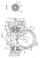
FIG. 1A is a sectional view of an exemplary electric power steering apparatus;FIG. 1B is a sectional view taken along the line A-A inFIG. 1A ; -
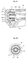
FIG. 2A is a partial sectional view of an electric power steering apparatus, showing a first embodiment of the present invention;FIG. 2B is a sectional view taken along the line C-C inFIG. 2A ; and -
FIG. 3A is a partial sectional view of an electric power steering apparatus, showing a second embodiment of the present invention;FIG. 3B is a sectional view taken along the line E-E inFIG. 3A . - In the exemplary electric
power steering apparatus 100 inFIGS. 1A and 1B , anelectric motor 101,ball bearings 103a, 103c for rotatably supporting aworm shaft 102 defined as a rotary shaft, an elastic portion 103b, anoutput shaft 105 of aworm wheel 104, etc., are disposed or fixed in predetermined positions in ahousing 101. - The
worm shaft 102 is constructed of aworm 102a formed substantially on the central portion thereof, and bearingsupport portions 102b formed on both sides of theworm 102a. A cylindrical connectingmember 108 is fixedly fitted on thebearing support portion 102b (the right side in the Figure) on the side of the ball bearing 103c proximal to theelectric motor 110. Afemale spline portion 108a is formed substantially in a half, in the axial direction, of an inner peripheral surface of the connectingmember 108. The connectingmember 108 is fitted in ashaft support hole 103d (an inner peripheral surface of an inner ring) of the ball bearing 103c so that the connectingmember 108 is movable in the axial directions. - On the other hand, a
male spline portion 110b is provided on an end portion of the motor shaft 110a of theelectric motor 110. Thismale spline portion 110b is loosely fitted in thefemale spline portion 108a of the connectingmember 108, whereby theworm shaft 102 is spline-connected to the motor shaft 110a in a state of being movable in the axial directions but unmovable in the rotational direction. This spline connecting portion is set so that substantially a half of the connecting portion in the axial direction is positioned within theshaft support hole 103d of thebearing 103c. The connectingmember 108 may be formed integrally with theworm 102a. - On the opposite side to the motor, the ball bearing 103a and an elastic portion 103b are disposed side by side in the axial direction. The bearing 103a has a function as a rolling bearing, and an outer ring thereof is fixedly fitted in a
bearing ring 114 defined as a cylindrical bearing holding member fixedly fitted in thehousing 101. Acylindrical buffer member 106 formed of a resin, etc., which is fixedly fitted on thebearing support portion 102b of theworm shaft 102, is loosely fitted in an inner ring of the bearing 103a. - The elastic portion 103b is constructed of a biasing
member 112 having an inside diameter substantially equal to an outside diameter of thebearing support portion 102b and being formed of resin, and anelastic body 113 fixedly fitting therein the biasingmember 112 and fitting rein, fixedly fitted in thebearing ring 114 and formed of a rubber, etc.. A position in which theelastic body 113 receives therein the biasingmember 112 is far eccentric in the meshing direction of theworm 102a. When incorporating theworm shaft 102 into the ball bearing 103a and the elastic portion 103b, however, theworm shaft 102 becomes substantially concentric with the bearing 103a, and hence theelastic body 113 deforms in a direction opposite to the meshing direction of theworm 102a, thereby producing a pre-load force in the meshing direction. - An outside diameter of the
buffer member 106 is set slightly smaller than an inside diameter of the inner ring of the bearing 103a. Let ΔS be a displacement quantity of theworm 102a in the meshing direction for eliminating the backlash, and an outside diameter of thebuffer member 106 is set to a dimension given by (an inner ring inside diameter - 2 ΔS). This is a value of such a degree that thebuffer member 106 is loosely fitted into the inner ring. - On the other hand,
elastic members 107 each assuming substantially a ring-shape are disposed on both sides of thebearing 103c proximal to theelectric motor 110 in the axial direction adjacently to thebearing 103c. These two elastic members 107,107 are disposed in the form of each being held by two pieces of ring-shapedholding members 107a and 107b. The holding members 107a positioned away from thebearing 103c are each fixedly fitted on the connectingmember 108. The holdingmembers 107b abutting on thebearing 103c are fixed to thebearing 103c and provided along the connectingmember 108 in a non-contact manner. Theelastic member 107 elastically extends and shrinks in the axial directions as the connectingmember 108 moves in the axial directions, thereby allowing theworm shaft 102 to move in the axial directions within the limit of the elasticity thereof. - The
worm wheel 104 is fixedly fitted on theoutput shaft 105 extending in the direction orthogonal to the axial direction of theworm shaft 102. Theoutput shaft 105 is so disposed as to be rotatably supported in a predetermined position of thehousing 101 in a state of theworm wheel 104 meshing with theworm 102a. A gear portion 104a of theworm wheel 104 is formed of a resin. - As illustrated in
FIG. 1A , in the meshing between theworm 102a and theworm wheel 104, let S (a + b = S) be a distance which is the sum of a working radius a of theworm 102a and a working radius b of theworm wheel 104, and theoutput shaft 105, the bearing 103c and theelectric motor 110 are disposed in thehousing 101 so that an axis-to-axis distance between the motor shaft 110a of theelectric motor 110 and theoutput shaft 105 of theworm wheel 104 and an axis-to-axis distance between the bearing 103c and theoutput shaft 105 become S. In this embodiment, the distance S is set such as S = 47.5 mm. It is effective that the displacement quantity ΔS of theworm 102a in the meshing direction for eliminating the backlash be set to an optimal value in a range of 0.1 mm through 0.5 mm. - In the construction described above, a position in which the biasing
member 112 is fitted in theelastic body 113 of the elastic portion 103b, is eccentric in the meshing direction of theworm 102a, and hence, when assembling theworm shaft 102 into the bearing 103a, theelastic body 113 deforms to produce a pre-load force in the meshing direction of theworm 102a. Then, theworm 102a and the gear portion 104a of theworm wheel 104 mesh with each other without the backlash. Thus, theworm 102a is kept in the so-called floating state. - Particularly, a rate at which a volume of the
elastic body 113 occupies the elastic portion 103b is taken large, whereby an initial eccentric quantity needed for generating the pre-load can be taken large and a spring constant of theelastic body 113 can be decreased. Therefore, even when a configuration of theworm 102a might change due to a scatter in working accuracy and an abrasion of the gear, it is feasible to stably maintain a fixed pre-load force and to effectively prevent the tooth-butting noises of the gears. - This pre-load force generates the friction to some extent when the
worm 102a meshes with theworm wheel 104, however, a thickness and a rigidity of theelastic body 113 are set so that a resistance force thereof does not become excessively large enough to cause a hindrance to a gear performance or to such a degree that a deviation in meshing does not occur due to an input of vibrations applied from tires. The rigidity of thiselastic body 113 can be set depending on hardness and a configuration of the rubber without any restriction. - Further, the
worm shaft 102 is movable in the axial directions, and hence, when a force is applied from the tire, theworm shaft 102 moves in the axial directions within a limit of elasticity of theelastic member 107, whereby theworm 102a and the gear portion 104a of theworm wheel 104 mesh with each other in proper positions to make it possible to absorb an impact. - In the portion of the ball bearing 103a, even in a case where a pressure is exerted on the
buffer member 106 due to an abrupt displacement of theworm 102a in the meshing direction thereof, thebuffer member 106 absorbs vibrations, thereby preventing an emission of noises of collision. Further, thebuffer member 106 is formed of the resin and is therefore effective in reducing a friction caused when theworm shaft 102 moves in the axial directions. - Moreover, in the ball bearing 103a, the minute gap ΔS is provided between the inner ring and the
buffer member 106 of theworm shaft 102, and hence there is absorbed a change in the axis-to-axis distance between theworm shaft 102 and theoutput shaft 105 due to the scatter in the working accuracy and to the meshing, whereby the stable operation can be ensured. - Further, the ball bearing 103a receives a load and a rotational torque acting in the meshing direction of the
worm 102a, which are generated when driving (when assisting) the apparatus, and controls the displacement of theworm 102a. Therefore, neither a large distortion nor load occurs in theelastic body 113 of the elastic portion 103b, thereby a durability of theelastic body 113 to be improved. - Thus, the fitting position of the
bearing support portion 102b into theelastic body 113 of the elastic portion 103b is set eccentric, the outside diameter of thebuffer member 106 is set comparatively smaller than the inside diameter of the inner ring of the bearing 103a, and theelastic member 107 is provided between theworm shaft 102 and thebearing 103c, which all cooperate to enable a pre-load mechanism to be easily structured, the backlash to be completely eliminated, the impact to be absorbed and the tooth-butting noises (rattle noises) to be restrained. - Next, a first embodiment of the present invention will be discussed with reference to
FIGS. 2A and 2B . The first embodiment of the invention is substantially the same as the exemplary apparatus ofFIGS. 1A and 1B , wherein the same members are marked with the same numerals or symbols, and their repetitive descriptions are omitted. A different point is that atorsion spring 117 is adopted as a substitute for theelastic body 113 of the elastic portion 103b. In this case, the clastic portion 103b is constructed of a biasingmember 112 for rotatably supporting thebearing support portion 102b of theworm shaft 102, thetorsion spring 117 wound on an outer peripheral portion of the biasingmember 112, and a latchingmember 118 that latches both side ends of thetorsion spring 117 in order to support the biasingmember 112 in a position eccentric in the meshing direction of theworm 102a and is fixedly fitted in thebearing ring 114. As shown inFIG. 2B , thetorsion spring 117 is open at its both side ends in an initial state but resiliently closes when incorporated into the latchingmember 118, and a biasing force generated at this time produces a pre-load force acting in the meshing direction in theworm 102a. In this construction also, the same effects as the exemplary apparatus ofFIGS. 1A and 1B has can be expected. - Next, a second embodiment of the present invention will be explained referring to
FIGS. 3A and 3B . The second embodiment of the present invention is substantially the same as the exemplary apparatus ofFIGS. 1A and 1B discussed above, wherein the same members are marked with the same numerals or symbols, and their repetitive descriptions are omitted. A different point is that thetorsion spring 117 is adopted as a substitute for theelastic body 113 of the elastic portion 103b. In this case, the elastic portion 103b is constructed of the biasingmember 112 rotatably supporting thebearing support portion 102b of theworm shaft 102, thetorsion spring 117 wound on the outer peripheral portion of the biasingmember 112, and the latchingmember 118 that latches both ends of thetorsion spring 117 in order to support the biasingmember 112 in a position eccentric in the meshing direction of theworm 102a and is fixedly fitted in thebearing ring 114. The biasingmember 112 is fitted at the its center thereof on theworm shaft 102b and generates a pre-load with respect to theworm 102a by dint of a rewinding force of thetorsion spring 117 wound on along the outer periphery thereof concentrically with a hole thereof. A contact portion between the biasingmember 112 and thetorsion spring 117 is opposed to thewheel 104 and is well short for an inner periphery of thetorsion spring 117, the structure being such that the pre-load generated by thetorsion spring 117 can be efficiently transferred to the biasingmember 112. Further, the latchingmember 118 is fixedly fitted in thehousing 101 and fixed by thebearing ring 114. The latchingmember 118 may be formed either by press working or of a resin, etc.. - As illustrate in FIG. 17B, the
torsion spring 117 has two pieces ofhooks 117a provided at both ends and disposed respectively in positions that are shifted by 180° in phase with respect to a winding center of thetorsion spring 117 in the initial state, wherein thesehooks 117a are latched by projections of the latchingmember 118. Moreover, thetorsion spring 117 is given a torsional torque beforehand. With this contrivance, the biasingmember 112 is, before assembling theworm 102a, held by theprojections 118a of the latching members in positions slightly shifted with respect to the elastic portion, and the biasingmember 112 is displaced by assembling theworm 102a with the result that the pre-load force is to be produced for theworm 102a. Therefore, any processes specializing in adjusting and in giving the pre-load are not required, and a built-in characteristic is improved. Moreover, the predetermined pre-load force can be ensured even by setting the spring constant comparatively low. In this construction also, the same effects as those in the exemplary apparatus ofFIGS. 1A and 1B can be expected. - Moreover, according to the second invention of the present invention, with respect to the motor-sided bearing, the elastic members are disposed on both sides in the axial direction thereof and adjacently thereto, and the worm is set slightly movable in the axial directions. Besides, the bearing on the distal side from the motor is the rolling bearing, and the elastic portion for biasing the worm in the meshing direction is provided on the rotary shaft. The outer ring of the bearing is fixedly fitted in the cylindrical bearing support member fixedly fitted in the housing, and the inner ring of this bearing loosely receives therein the cylindrical buffer member fixedly fitted on the rotary shaft. The elastic portion is constructed of the biasing member for rotatably supporting the rotary shaft and of the elastic body receiving therein this biasing member in the position that is eccentric in the meshing direction of the worm with respect to the axis of the bearing, this elastic body being fixed in the vicinity of the bearing support member. Therefore, the worm has the pre-load force produced in the meshing direction thereof, and, with the simple construction, the backlash can be eliminated completely.
- Particularly, according to an embodiment, the rate at which the volume of the elastic body occupies the elastic portion is taken large, whereby the initial eccentric quantity needed for generating the pre-load can be taken large and the spring constant of the elastic body can be decreased. Therefore, even when the configuration of the worm might change due to the scatter in working accuracy and the abrasion of the gear, it is feasible to stably maintain the fixed pre-load force and to effectively prevent the tooth-butting noises of the gears.
- Further, according to an embodiment, when the force is applied to the rotary shaft, the rotary shaft moves in the axial directions within the limit of the elasticity of the elastic member, with the result that the worm and the gear portion of the worm wheel mesh with each other in the proper positions to absorb the impact. It is therefore possible to reduce the tooth-butting noises without any decline of the transmission performance of the auxiliary steering force.
- Moreover, according to an embodiment, the bearing receives the load and the rotational torque acting in the meshing direction of the worm, which are generated when driving the apparatus, thus controlling the displacement of the worm. Therefore, neither the large distortion nor load occurs in the elastic body of the elastic portion, which leads to an improvement of a lifetime of the elastic body.
Claims (8)
- An electric power steering apparatus comprising:a housing (101);a motor (110) for transmitting an auxiliary steering force to a rotary shaft (102) through a motor shaft;a worm gear mechanism comprising a worm (102a) formed on or fitted on said rotary shaft,an output shaft (105) transmitting a steering force for steering an axle and which is rotatably supported in a predetermined position of said housing, and a worm wheel (104) formed on or fitted on said output shaft in a way that meshes with said worm, the worm gear mechanism being installed in such a position that a length which is the sum of a working radius of said worm and a working radius of said worm wheel becomes an axis-to-axis distance between said output shaft and said motor shaft,a first bearing (103c) and a second bearing (103a) being provided respectively in a proximal position to said motor and in a distal position from said motor in said housing, disposed respectively in positions on both sides of said worm and rotatably supporting said rotary shaft (102);wherein elastic members (107, 107) are disposed on both sides, in the axial direction, of said first bearing (103c) adjacent said first bearing, said rotary shaft being set slightly movable in the axial direction,said second bearing (103a) positioned away from said motor (110) is a rolling bearing, an elastic portion (103b) being provided on said rotary shaft (102) and biasing said worm (102a) in the meshing direction in parallel with said rolling bearing;an outer ring of said rolling bearing being fixedly fitted in a cylindrical bearing holding member (114) fixedly fitted in said housing, an inner ring of said rolling bearing loosely receiving therein a cylindrical buffer member (106) fixedly fitted on said rotary shaft;said elastic portion (103b) being constructed of a biasing member (112) rotatably supporting said rotary shaft, and a torsion spring (117) wound on along a periphery of said biasing member, and a latching member (118) resiliently latching both side end portions of said torsion spring and supporting said biasing member in a position eccentric in the meshing direction of said worm with respect to the axis of said rolling bearing and fixed in the vicinity of said bearing holding member (114).
- An electric power steering apparatus according to claim 1, wherein said buffer member (106) is fixedly fitted on said inner ring of said rolling bearing, and loosely receives therein said rotary shaft (102).
- An electric power steering apparatus according to claim 1 or 2, wherein at least a half, in the axial direction, of a spline connecting portion between said rotary shaft (102) and said motor shaft is positioned within a shaft support hole of said first bearing (103c).
- An electric power steering apparatus according to any of claims 1 to 3, wherein said elastic members (107, 107) of said first bearing or said rotary shaft in the vicinity of said second bearing or both of said elastic members (107, 107) and said rotary shaft, is or are provided with a stopper (107a) for controlling a quantity of movement of said rotary shaft (102) in the axial direction.
- An electric power steering apparatus according to any preceding claim, wherein the motor (110) is attached to the housing (101).
- An electric power steering apparatus according to any preceding claim, wherein said worm (102a) has a gear portion formed of a metal or a resin.
- An electric power steering apparatus according to any preceding claim, wherein the worm wheel (104) has a gear portion (4a) formed of a resin.
- A vehicle provided with an electric power steering apparatus according to any preceding claim.
Applications Claiming Priority (9)
| Application Number | Priority Date | Filing Date | Title |
|---|---|---|---|
| JP2001368886 | 2001-12-03 | ||
| JP2001368886 | 2001-12-03 | ||
| JP2002079215 | 2002-03-20 | ||
| JP2002078511 | 2002-03-20 | ||
| JP2002078511 | 2002-03-20 | ||
| JP2002079215 | 2002-03-20 | ||
| JP2002173096 | 2002-06-13 | ||
| JP2002173096 | 2002-06-13 | ||
| PCT/JP2002/012651 WO2003047948A1 (en) | 2001-12-03 | 2002-12-03 | Electric power steering device |
Publications (3)
| Publication Number | Publication Date |
|---|---|
| EP1452419A1 EP1452419A1 (en) | 2004-09-01 |
| EP1452419A4 EP1452419A4 (en) | 2005-09-14 |
| EP1452419B1 true EP1452419B1 (en) | 2010-07-14 |
Family
ID=27482717
Family Applications (1)
| Application Number | Title | Priority Date | Filing Date |
|---|---|---|---|
| EP02783745A Expired - Lifetime EP1452419B1 (en) | 2001-12-03 | 2002-12-03 | Electric power steering device |
Country Status (7)
| Country | Link |
|---|---|
| US (2) | US7077235B2 (en) |
| EP (1) | EP1452419B1 (en) |
| JP (1) | JP4196831B2 (en) |
| CN (1) | CN1323005C (en) |
| AU (1) | AU2002349690A1 (en) |
| DE (1) | DE60237029D1 (en) |
| WO (1) | WO2003047948A1 (en) |
Cited By (2)
| Publication number | Priority date | Publication date | Assignee | Title |
|---|---|---|---|---|
| TWI474906B (en) * | 2011-11-22 | 2015-03-01 | Hon Hai Prec Ind Co Ltd | Gear transmission decice and robot arm having the same |
| DE102020215344A1 (en) | 2020-12-04 | 2022-06-09 | Zf Automotive Germany Gmbh | Steering device with a worm gear |
Families Citing this family (102)
| Publication number | Priority date | Publication date | Assignee | Title |
|---|---|---|---|---|
| CN100411934C (en) | 2002-12-09 | 2008-08-20 | 日本精工株式会社 | Electric power steering apparatus |
| JP3951913B2 (en) * | 2002-12-24 | 2007-08-01 | 株式会社ジェイテクト | Electric power steering device |
| EP1501715A2 (en) | 2003-02-20 | 2005-02-02 | NSK Ltd. | Electric-powered power steering apparatus |
| EP2371675B1 (en) * | 2003-04-18 | 2012-10-17 | Jtekt Corporation | Electric power steering device |
| JP4906955B2 (en) * | 2003-06-25 | 2012-03-28 | 日本精工株式会社 | Worm speed reducer and electric power steering device |
| DE112004000679T5 (en) * | 2003-06-25 | 2006-04-06 | Nsk Steering Systems Co., Ltd. | Electric power steering |
| JP4716679B2 (en) * | 2003-06-25 | 2011-07-06 | 日本精工株式会社 | Worm speed reducer and electric power steering device |
| JP2005112241A (en) * | 2003-10-09 | 2005-04-28 | Nsk Ltd | Electric power steering device |
| JP4356485B2 (en) * | 2004-03-09 | 2009-11-04 | 株式会社ジェイテクト | Electric power steering device |
| DE102004051218B4 (en) * | 2004-07-01 | 2008-01-17 | Tedrive Holding Bv | Electric steering gear with an electric motor and a reduction gear |
| JP3880982B2 (en) * | 2004-07-01 | 2007-02-14 | 株式会社共立 | Oil pump device for lubricating the saw chain |
| JP2006070986A (en) * | 2004-09-01 | 2006-03-16 | Ntn Corp | Shaft member for dynamic-pressure bearing device |
| DE102004054510A1 (en) * | 2004-11-11 | 2006-05-18 | Zf Lenksysteme Gmbh | steering |
| JP2006214570A (en) * | 2005-02-07 | 2006-08-17 | Ntn Corp | Support structure for shaft |
| KR100621347B1 (en) * | 2005-09-20 | 2006-09-07 | 주식회사 만도 | Electric power steering apparatus for automotive vehicle |
| KR100723732B1 (en) * | 2005-11-02 | 2007-05-30 | 주식회사 만도 | Electric Power Steering System Equipped with Worm Gear Clearance Compensator |
| US8282523B2 (en) | 2005-12-27 | 2012-10-09 | Mitsubishi Heavy Industries, Ltd. | Planetary roller reducer |
| JP2007182178A (en) * | 2006-01-10 | 2007-07-19 | Nsk Ltd | Worm decelerator and electric power steering device |
| JP4872372B2 (en) | 2006-02-14 | 2012-02-08 | 株式会社ジェイテクト | Electric power steering device |
| CN100398876C (en) * | 2006-03-17 | 2008-07-02 | 中国科学院上海光学精密机械研究所 | Worm gear clearance eliminating device |
| JP2007285472A (en) * | 2006-04-19 | 2007-11-01 | Nsk Ltd | Reduction gear and electric power steering device having this reduction gear |
| GB0608577D0 (en) * | 2006-05-02 | 2006-06-07 | Trw Lucasvarity Electric Steer | Improvements relating to electric power assisted steering systems |
| JP5017927B2 (en) * | 2006-05-31 | 2012-09-05 | 日本精工株式会社 | Electric power steering device |
| KR100816401B1 (en) * | 2006-07-05 | 2008-03-27 | 주식회사 만도 | Electronic Steering Apparatus |
| WO2008068912A1 (en) * | 2006-12-01 | 2008-06-12 | Nsk Ltd. | Electric power steering device |
| JP2010095006A (en) * | 2007-01-16 | 2010-04-30 | Nsk Ltd | Electric power steering device |
| JP2008174024A (en) * | 2007-01-16 | 2008-07-31 | Nsk Ltd | Electric power steering device |
| JP2008173993A (en) * | 2007-01-16 | 2008-07-31 | Nsk Ltd | Electric power steering device |
| JP2008254495A (en) * | 2007-04-02 | 2008-10-23 | Jtekt Corp | Motor-driven power steering device |
| US8672086B2 (en) * | 2007-08-02 | 2014-03-18 | Marine Canada Acquisition Inc. | Torque sensor type power steering system with solid steering shaft and vehicle therewith |
| JP5176549B2 (en) * | 2008-01-08 | 2013-04-03 | 日本精工株式会社 | Electric power steering device |
| DE102008000506A1 (en) * | 2008-03-04 | 2009-09-17 | Zf Lenksysteme Gmbh | Schraubradgetriebe with axially elastic shaft bearing and thus equipped electric power steering |
| JP2009286387A (en) * | 2008-05-27 | 2009-12-10 | Hyundai Motor Co Ltd | Device for reducing noise of electric power steering device |
| FR2935669B1 (en) * | 2008-09-08 | 2010-09-24 | Jtekt Europe Sas | POWER ASSISTED STEERING COMPONENT OF A MOTOR VEHICLE |
| DE102008042281A1 (en) * | 2008-09-23 | 2010-03-25 | Zf Lenksysteme Gmbh | Shaft bearing for use in worm gear of electric power steering system of motor vehicle, has holder connected with shaft, accommodating inner ring and comprising recesses enabling pivot movement towards section of holder |
| DE102008056024A1 (en) * | 2008-11-05 | 2010-05-20 | Ab Skf | Bearing arrangement for bearing worm shaft of steering gear of vehicle, has bearings arranged relative to housing by element such that deflection of bearings in radial and axial directions is possible against spring force of element |
| US8549945B2 (en) * | 2008-11-12 | 2013-10-08 | Mando Corporation | Reducer of electronic power steering apparatus |
| US8307938B2 (en) * | 2009-01-22 | 2012-11-13 | Showa Corporation | Electric power steering apparatus |
| JP5210218B2 (en) * | 2009-03-27 | 2013-06-12 | 株式会社ショーワ | Electric power steering device |
| WO2010085346A1 (en) * | 2009-01-23 | 2010-07-29 | Skf Usa Inc. | Bearing assembly for a power steering mechanism |
| AT10804U1 (en) * | 2009-06-04 | 2009-10-15 | Neustifter Johann | METHOD FOR CONVERTING A DISTRIBUTION GEARBOX FOR MULTIPLE DISPENSES |
| JP2009257596A (en) * | 2009-08-11 | 2009-11-05 | Ntn Corp | Vibration damping bearing unit |
| JP5353640B2 (en) * | 2009-11-02 | 2013-11-27 | 日本精工株式会社 | Electric power steering device |
| US8905185B2 (en) * | 2009-12-23 | 2014-12-09 | Mando Corporation | Reducer of electric power steering apparatus |
| JP5418834B2 (en) * | 2009-12-28 | 2014-02-19 | 株式会社ジェイテクト | Electric power steering device |
| DE102010002958A1 (en) * | 2010-03-17 | 2011-09-22 | Zf Lenksysteme Gmbh | Power steering |
| JP5641195B2 (en) * | 2010-04-13 | 2014-12-17 | 株式会社ジェイテクト | Electric power steering device |
| US8590412B2 (en) * | 2010-06-18 | 2013-11-26 | Macauto Industrial Co., Ltd. | Driving apparatus with a vibration limiter for worm gear |
| US8381868B2 (en) * | 2010-08-30 | 2013-02-26 | Jtekt Corporation | Electric power steering system |
| DE102010044168A1 (en) * | 2010-11-19 | 2012-05-24 | Zf Lenksysteme Gmbh | Power steering, in particular for a motor vehicle |
| JP5671984B2 (en) * | 2010-12-03 | 2015-02-18 | 株式会社ジェイテクト | Reducer, electric power steering apparatus including the same, and method of manufacturing the reducer |
| DE102010054828A1 (en) * | 2010-12-16 | 2012-06-21 | Thyssenkrupp Presta Ag | Power steering with spindle drive |
| KR101306457B1 (en) * | 2011-01-17 | 2013-09-09 | 주식회사 만도 | Electric Tilt Steering Apparatus for Vehicle |
| FR2972514B1 (en) * | 2011-03-09 | 2013-09-06 | Skf Ab | WEAR COMPENSATION DEVICE FOR GEAR. |
| DE102011013957A1 (en) * | 2011-03-11 | 2012-09-13 | Thyssenkrupp Presta Ag | Electrically assisted power steering with immobilizer |
| US9638307B2 (en) | 2012-04-25 | 2017-05-02 | Jtekt Corporation | Electric power steering device |
| JP6020893B2 (en) * | 2012-07-27 | 2016-11-02 | 株式会社ジェイテクト | Electric power steering device |
| US9533701B2 (en) * | 2012-08-07 | 2017-01-03 | Steering Solutions Ip Holding Corporation | Steering column assist system |
| US9664273B2 (en) | 2012-08-07 | 2017-05-30 | Steering Solutions Ip Holding Corporation | Steering column assist system |
| CN102904376B (en) * | 2012-10-09 | 2015-09-23 | 浙江胜华波电器股份有限公司 | Transmission buffer type wiper motor and transmission bolster thereof installation method is set |
| US9923428B2 (en) * | 2013-02-28 | 2018-03-20 | Nidec Sankyo Corporation | Motor device having transmission member that is movable relative to motor side coupling part and worm gear side coupling part |
| DE102013003749A1 (en) * | 2013-03-06 | 2014-09-11 | Thyssenkrupp Presta Aktiengesellschaft | Angularly movable bearing arrangement for pinions in reduction gears of electromechanical steering systems |
| DE102013204432A1 (en) * | 2013-03-14 | 2014-10-02 | Robert Bosch Gmbh | Transmission drive unit and comfort drive with a transmission drive unit |
| JP6242065B2 (en) * | 2013-03-29 | 2017-12-06 | 住友重機械工業株式会社 | Manufacturing method of reduction gear group |
| US9145164B2 (en) | 2013-04-12 | 2015-09-29 | Rane TRW Steering Systems Limited | Integral hydraulic power steering gear |
| DE102013207142B4 (en) * | 2013-04-19 | 2014-12-11 | Ford Global Technologies, Llc | worm gear |
| JP6067112B2 (en) | 2013-07-01 | 2017-01-25 | 株式会社ハーモニック・ドライブ・システムズ | Hollow wave gear device |
| JP6164477B2 (en) * | 2013-07-25 | 2017-07-19 | 株式会社ジェイテクト | Electric power steering device |
| JP2015031388A (en) * | 2013-08-07 | 2015-02-16 | オイレス工業株式会社 | Elastic member used for electrically-driven power steering device and electrically-driven power steering device with the elastic member |
| CN103616105B (en) * | 2013-11-27 | 2015-07-22 | 天津大学 | Device capable of detecting transmission force and performing transmission |
| JP6278235B2 (en) * | 2013-12-27 | 2018-02-14 | 株式会社ジェイテクト | Planetary roller type transmission |
| CN103818471A (en) * | 2014-03-17 | 2014-05-28 | 安徽江淮汽车股份有限公司 | Worm abnormal-sound-preventing supporting structure of electric power steering column |
| DE102014107073A1 (en) * | 2014-05-20 | 2015-11-26 | Robert Bosch Automotive Steering Gmbh | steering gear |
| WO2016047189A1 (en) * | 2014-09-26 | 2016-03-31 | 日本精工株式会社 | Electric power steering device |
| JP6032257B2 (en) | 2014-10-09 | 2016-11-24 | 日本精工株式会社 | Control method for electric power steering apparatus, electric power steering apparatus and vehicle equipped with the same |
| US9744987B2 (en) * | 2015-04-29 | 2017-08-29 | Steering Solutions Ip Holding Corporation | Worm shaft subassembly |
| FR3035933B1 (en) * | 2015-05-05 | 2017-06-09 | Moteurs Leroy-Somer | ELECTROMECHANICAL ASSEMBLY COMPRISING AN ELECTRICAL MACHINE COUPLED WITH A REDUCER |
| US10274008B2 (en) * | 2015-06-19 | 2019-04-30 | Steering Solutions Ip Holding Corporation | Axial load bearing assembly |
| EP3315817A4 (en) * | 2015-06-29 | 2018-07-25 | NSK Ltd. | Worm speed reducer |
| US10160479B2 (en) | 2015-07-09 | 2018-12-25 | Steering Solutions Ip Holding Corporation | Eccentric adjustment retainer |
| KR102384166B1 (en) * | 2015-12-24 | 2022-04-08 | 주식회사 만도 | Reducer of Electric Power Steering Apparatus |
| DE102016211694B3 (en) * | 2016-06-29 | 2017-10-05 | Ford Global Technologies, Llc | Transmission unit for a motor vehicle |
| DE102016008017B4 (en) * | 2016-07-04 | 2022-02-24 | AUMA Drives GmbH | Worm gear with adjustable backlash and method for adjusting the backlash |
| DE102017205516A1 (en) * | 2017-03-31 | 2018-10-04 | Ford Global Technologies, Llc | Power steering for a motor vehicle and motor vehicle |
| FR3066970B1 (en) * | 2017-06-02 | 2021-01-01 | Valeo Systemes Dessuyage | MOTOR-REDUCER FOR MOTOR VEHICLE WIPING SYSTEM |
| DE102017211461B4 (en) * | 2017-07-05 | 2024-06-27 | Robert Bosch Gmbh | Steering gear |
| DE102017117724A1 (en) * | 2017-08-04 | 2019-02-07 | Thyssenkrupp Ag | Game reduction of a worm gear of an electromechanical power steering by means of bimetallic spring |
| JP6975379B2 (en) * | 2017-08-07 | 2021-12-01 | 株式会社ジェイテクト | Warm reducer |
| DE102017123150A1 (en) * | 2017-10-05 | 2019-04-11 | Thyssenkrupp Ag | Electromechanical power steering with helical gear and a compensation device for supporting a floating bearing on the gearbox |
| KR101993295B1 (en) * | 2017-12-19 | 2019-06-26 | 주식회사 만도 | Reducer of Electric Power Steering Apparatus |
| KR102369862B1 (en) * | 2017-12-29 | 2022-03-04 | 주식회사 만도 | Reducer of Electric Power Steering Apparatus |
| DE102018200090A1 (en) * | 2018-01-04 | 2019-07-04 | Robert Bosch Gmbh | worm gear |
| DE102018201858A1 (en) * | 2018-02-07 | 2019-08-29 | Robert Bosch Gmbh | Steering gear, steering system and method for producing a swivel ring for a steering gear |
| CN108639144A (en) * | 2018-04-18 | 2018-10-12 | 奇瑞汽车股份有限公司 | A kind of electric steering column output shaft fixing device |
| KR102419686B1 (en) * | 2018-05-09 | 2022-07-12 | 주식회사 만도 | Reducer of Electric Power Steering Apparatus |
| KR102033558B1 (en) * | 2018-05-18 | 2019-10-17 | 주식회사 만도 | Reducer of Electric power steering apparatus |
| DE102018129061A1 (en) * | 2018-11-19 | 2020-05-20 | Trw Automotive Gmbh | Process for the production of steering systems assisted by an electric motor and steering system supported by an electric motor |
| CN113196625A (en) * | 2018-12-17 | 2021-07-30 | 美蓓亚三美株式会社 | Rotating device |
| CN110937014A (en) * | 2019-10-29 | 2020-03-31 | 昌辉汽车转向系统(黄山)有限公司 | Worm and gear clearance self-adjusting structure |
| CN113176498B (en) * | 2021-03-24 | 2023-05-23 | 柯马(上海)工程有限公司 | Main shaft floating mechanism of dynamometer |
| EP4296527A1 (en) * | 2022-06-23 | 2023-12-27 | Volvo Car Corporation | Housing for bearing |
| US20240128833A1 (en) * | 2022-10-14 | 2024-04-18 | Novanta Corporation | Systems and methods for providing wobble reduction in galvanometers |
Family Cites Families (29)
| Publication number | Priority date | Publication date | Assignee | Title |
|---|---|---|---|---|
| DE2327652C2 (en) | 1973-05-30 | 1975-07-24 | Gebrueder Boehringer Gmbh, 7320 Goeppingen | Feed gear for an oil feed head on a deep hole drilling machine |
| JPH07103356B2 (en) | 1986-04-11 | 1995-11-08 | 武田薬品工業株式会社 | Adhesion method |
| JPH03112784A (en) | 1989-09-27 | 1991-05-14 | Mazda Motor Corp | Rear-wheel steering device for vehicle |
| JP3909908B2 (en) * | 1997-04-03 | 2007-04-25 | カヤバ工業株式会社 | Power transmission device |
| GB2327652B (en) * | 1997-05-29 | 2001-04-18 | Nsk Ltd | Electric power assisted steering apparatus |
| JP3376869B2 (en) | 1997-05-29 | 2003-02-10 | 日本精工株式会社 | Electric power steering device |
| GB9718574D0 (en) * | 1997-09-03 | 1997-11-05 | Lucas Ind Plc | Improvements relating to gears |
| DE19747638C1 (en) * | 1997-10-29 | 1999-07-01 | Zahnradfabrik Friedrichshafen | Electrically assisted power steering for motor vehicles |
| JP3716616B2 (en) | 1998-04-24 | 2005-11-16 | 日本精工株式会社 | Worm reducer and linear actuator with worm reducer |
| GB9812844D0 (en) | 1998-06-16 | 1998-08-12 | Lucas Ind Plc | Improvements relating to electrical power assisted steering |
| JP3613693B2 (en) | 1998-07-27 | 2005-01-26 | 光洋精工株式会社 | Electric steering device |
| JP4221825B2 (en) | 1999-06-28 | 2009-02-12 | 株式会社ジェイテクト | Electric steering device |
| JP2001108025A (en) | 1999-10-08 | 2001-04-20 | Koyo Seiko Co Ltd | Electric steering device |
| JP3624309B2 (en) | 2000-02-21 | 2005-03-02 | 光洋精工株式会社 | Electric steering device |
| JP3624308B2 (en) | 2000-02-21 | 2005-03-02 | 光洋精工株式会社 | Electric steering device |
| JP3658682B2 (en) | 2000-03-27 | 2005-06-08 | 光洋精工株式会社 | Electric steering device |
| JP3658683B2 (en) * | 2000-05-17 | 2005-06-08 | 光洋精工株式会社 | Electric steering device |
| FR2808759B1 (en) | 2000-05-10 | 2005-08-26 | Koyo Seiko Co | POWER ASSISTED STEERING APPARATUS |
| JP3643950B2 (en) * | 2000-05-10 | 2005-04-27 | 光洋精工株式会社 | Electric steering device |
| JP3653611B2 (en) * | 2000-05-18 | 2005-06-02 | 光洋精工株式会社 | Electric steering device |
| JP2002021943A (en) | 2000-07-04 | 2002-01-23 | Koyo Seiko Co Ltd | Motor-driven steering device |
| JP2002037094A (en) | 2000-05-18 | 2002-02-06 | Koyo Seiko Co Ltd | Electric steering system |
| JP3747152B2 (en) | 2000-09-20 | 2006-02-22 | 光洋精工株式会社 | Gear mechanism and electric power steering device |
| DE10051306A1 (en) * | 2000-10-17 | 2002-04-18 | Bosch Gmbh Robert | Gear for a motor vehicle steering assembly used e.g. in a servo unit of an electrical power-assisted steering arrangement comprises a pinion arranged on a shaft so that it does not rotate, and a toothed wheel interacting with the pinion |
| FR2819774B1 (en) * | 2001-01-19 | 2006-09-29 | Koyo Seiko Co | ARTICULATION AND ASSISTED STEERING SYSTEM USING THE SAME |
| JP3888607B2 (en) * | 2001-03-05 | 2007-03-07 | 本田技研工業株式会社 | Electric power steering device |
| JP3982186B2 (en) * | 2001-03-05 | 2007-09-26 | 株式会社ジェイテクト | Worm gear device and electric power steering device using the worm gear device |
| JP4654532B2 (en) | 2001-04-25 | 2011-03-23 | 株式会社ジェイテクト | Joint structure, reduction mechanism and steering assist device using the same |
| DE60328544D1 (en) * | 2002-02-04 | 2009-09-03 | Jtekt Corp | Electric power steering |
-
2002
- 2002-12-03 CN CNB028241665A patent/CN1323005C/en not_active Expired - Lifetime
- 2002-12-03 JP JP2003549153A patent/JP4196831B2/en not_active Expired - Lifetime
- 2002-12-03 WO PCT/JP2002/012651 patent/WO2003047948A1/en active Application Filing
- 2002-12-03 AU AU2002349690A patent/AU2002349690A1/en not_active Abandoned
- 2002-12-03 US US10/491,564 patent/US7077235B2/en not_active Expired - Lifetime
- 2002-12-03 EP EP02783745A patent/EP1452419B1/en not_active Expired - Lifetime
- 2002-12-03 DE DE60237029T patent/DE60237029D1/en not_active Expired - Lifetime
-
2006
- 2006-04-12 US US11/402,006 patent/US7188700B2/en not_active Expired - Lifetime
Cited By (2)
| Publication number | Priority date | Publication date | Assignee | Title |
|---|---|---|---|---|
| TWI474906B (en) * | 2011-11-22 | 2015-03-01 | Hon Hai Prec Ind Co Ltd | Gear transmission decice and robot arm having the same |
| DE102020215344A1 (en) | 2020-12-04 | 2022-06-09 | Zf Automotive Germany Gmbh | Steering device with a worm gear |
Also Published As
| Publication number | Publication date |
|---|---|
| CN1323005C (en) | 2007-06-27 |
| JP4196831B2 (en) | 2008-12-17 |
| EP1452419A1 (en) | 2004-09-01 |
| AU2002349690A1 (en) | 2003-06-17 |
| US20060191738A1 (en) | 2006-08-31 |
| CN1599680A (en) | 2005-03-23 |
| US7077235B2 (en) | 2006-07-18 |
| DE60237029D1 (en) | 2010-08-26 |
| JPWO2003047948A1 (en) | 2005-04-14 |
| WO2003047948A1 (en) | 2003-06-12 |
| EP1452419A4 (en) | 2005-09-14 |
| US20040245040A1 (en) | 2004-12-09 |
| US7188700B2 (en) | 2007-03-13 |
Similar Documents
| Publication | Publication Date | Title |
|---|---|---|
| EP1452419B1 (en) | Electric power steering device | |
| US9902421B2 (en) | Worm reduction gear and steering mechanism | |
| KR102281674B1 (en) | Reducer for vehicle | |
| EP2450262B1 (en) | Electric power steering system | |
| JP5039036B2 (en) | Power steering device, reduction mechanism and bearing holder | |
| JP4442421B2 (en) | Electric power steering device | |
| US8381868B2 (en) | Electric power steering system | |
| JP4356485B2 (en) | Electric power steering device | |
| EP3088278B1 (en) | Worm reduction gear and steering system | |
| JP4979801B2 (en) | Worm speed reducer and electric power steering device | |
| WO2004091997A1 (en) | Electric power steering device | |
| JP2006175891A (en) | Electric power steering device | |
| JP4501068B2 (en) | Electric power steering device | |
| JP4052218B2 (en) | Electric power steering device | |
| JP5062465B2 (en) | Steering device | |
| US6339967B1 (en) | Vibration dampening hypoid gear structure | |
| JP2004255988A (en) | Rack and pinion type steering device | |
| JP4622638B2 (en) | Rack and pinion type steering gear | |
| JP6653223B2 (en) | Power steering device | |
| JPH08207792A (en) | Power steering system | |
| JP4178321B2 (en) | Rack and pinion steering system | |
| JP5353640B2 (en) | Electric power steering device | |
| JP5018361B2 (en) | Electric power steering device | |
| JP2023007883A (en) | Worm reduction gear |
Legal Events
| Date | Code | Title | Description |
|---|---|---|---|
| PUAI | Public reference made under article 153(3) epc to a published international application that has entered the european phase |
Free format text: ORIGINAL CODE: 0009012 |
|
| 17P | Request for examination filed |
Effective date: 20040428 |
|
| AK | Designated contracting states |
Kind code of ref document: A1 Designated state(s): AT BE BG CH CY CZ DE DK EE ES FI FR GB GR IE IT LI LU MC NL PT SE SI SK TR |
|
| AX | Request for extension of the european patent |
Extension state: AL LT LV MK RO |
|
| A4 | Supplementary search report drawn up and despatched |
Effective date: 20050803 |
|
| GRAP | Despatch of communication of intention to grant a patent |
Free format text: ORIGINAL CODE: EPIDOSNIGR1 |
|
| GRAS | Grant fee paid |
Free format text: ORIGINAL CODE: EPIDOSNIGR3 |
|
| GRAA | (expected) grant |
Free format text: ORIGINAL CODE: 0009210 |
|
| AK | Designated contracting states |
Kind code of ref document: B1 Designated state(s): DE FR GB |
|
| REG | Reference to a national code |
Ref country code: GB Ref legal event code: FG4D |
|
| REF | Corresponds to: |
Ref document number: 60237029 Country of ref document: DE Date of ref document: 20100826 Kind code of ref document: P |
|
| PLBE | No opposition filed within time limit |
Free format text: ORIGINAL CODE: 0009261 |
|
| STAA | Information on the status of an ep patent application or granted ep patent |
Free format text: STATUS: NO OPPOSITION FILED WITHIN TIME LIMIT |
|
| 26N | No opposition filed |
Effective date: 20110415 |
|
| REG | Reference to a national code |
Ref country code: DE Ref legal event code: R097 Ref document number: 60237029 Country of ref document: DE Effective date: 20110415 |
|
| REG | Reference to a national code |
Ref country code: FR Ref legal event code: PLFP Year of fee payment: 14 |
|
| REG | Reference to a national code |
Ref country code: FR Ref legal event code: PLFP Year of fee payment: 15 |
|
| REG | Reference to a national code |
Ref country code: FR Ref legal event code: PLFP Year of fee payment: 16 |
|
| PGFP | Annual fee paid to national office [announced via postgrant information from national office to epo] |
Ref country code: FR Payment date: 20201112 Year of fee payment: 19 Ref country code: GB Payment date: 20201126 Year of fee payment: 19 |
|
| PGFP | Annual fee paid to national office [announced via postgrant information from national office to epo] |
Ref country code: DE Payment date: 20211102 Year of fee payment: 20 |
|
| GBPC | Gb: european patent ceased through non-payment of renewal fee |
Effective date: 20211203 |
|
| PG25 | Lapsed in a contracting state [announced via postgrant information from national office to epo] |
Ref country code: GB Free format text: LAPSE BECAUSE OF NON-PAYMENT OF DUE FEES Effective date: 20211203 |
|
| PG25 | Lapsed in a contracting state [announced via postgrant information from national office to epo] |
Ref country code: FR Free format text: LAPSE BECAUSE OF NON-PAYMENT OF DUE FEES Effective date: 20211231 |
|
| REG | Reference to a national code |
Ref country code: DE Ref legal event code: R071 Ref document number: 60237029 Country of ref document: DE |